EP4212720A1 - Tour pour une éolienne et éolienne correspondante - Google Patents
Tour pour une éolienne et éolienne correspondante Download PDFInfo
- Publication number
- EP4212720A1 EP4212720A1 EP23151574.3A EP23151574A EP4212720A1 EP 4212720 A1 EP4212720 A1 EP 4212720A1 EP 23151574 A EP23151574 A EP 23151574A EP 4212720 A1 EP4212720 A1 EP 4212720A1
- Authority
- EP
- European Patent Office
- Prior art keywords
- tower
- section
- height
- wall elements
- soft
- Prior art date
- Legal status (The legal status is an assumption and is not a legal conclusion. Google has not performed a legal analysis and makes no representation as to the accuracy of the status listed.)
- Withdrawn
Links
- 239000004567 concrete Substances 0.000 claims abstract description 56
- 230000007423 decrease Effects 0.000 claims abstract description 8
- 238000009434 installation Methods 0.000 claims abstract description 6
- 239000000463 material Substances 0.000 claims description 58
- 230000005284 excitation Effects 0.000 claims description 12
- 239000011372 high-strength concrete Substances 0.000 claims description 8
- 239000000725 suspension Substances 0.000 claims description 4
- 238000005452 bending Methods 0.000 abstract description 11
- 238000009826 distribution Methods 0.000 description 28
- 238000010586 diagram Methods 0.000 description 13
- 230000007935 neutral effect Effects 0.000 description 10
- 239000000835 fiber Substances 0.000 description 6
- 229910000831 Steel Inorganic materials 0.000 description 5
- 239000010959 steel Substances 0.000 description 5
- 230000014509 gene expression Effects 0.000 description 4
- 230000007704 transition Effects 0.000 description 4
- 239000011513 prestressed concrete Substances 0.000 description 3
- 230000015572 biosynthetic process Effects 0.000 description 2
- 239000004020 conductor Substances 0.000 description 2
- 238000010276 construction Methods 0.000 description 2
- 230000003247 decreasing effect Effects 0.000 description 2
- 238000006073 displacement reaction Methods 0.000 description 2
- 230000000694 effects Effects 0.000 description 2
- 230000000712 assembly Effects 0.000 description 1
- 238000000429 assembly Methods 0.000 description 1
- 150000001875 compounds Chemical class 0.000 description 1
- 238000000034 method Methods 0.000 description 1
- 239000002689 soil Substances 0.000 description 1
Images




Classifications
-
- F—MECHANICAL ENGINEERING; LIGHTING; HEATING; WEAPONS; BLASTING
- F03—MACHINES OR ENGINES FOR LIQUIDS; WIND, SPRING, OR WEIGHT MOTORS; PRODUCING MECHANICAL POWER OR A REACTIVE PROPULSIVE THRUST, NOT OTHERWISE PROVIDED FOR
- F03D—WIND MOTORS
- F03D9/00—Adaptations of wind motors for special use; Combinations of wind motors with apparatus driven thereby; Wind motors specially adapted for installation in particular locations
- F03D9/10—Combinations of wind motors with apparatus storing energy
- F03D9/12—Combinations of wind motors with apparatus storing energy storing kinetic energy, e.g. using flywheels
-
- F—MECHANICAL ENGINEERING; LIGHTING; HEATING; WEAPONS; BLASTING
- F03—MACHINES OR ENGINES FOR LIQUIDS; WIND, SPRING, OR WEIGHT MOTORS; PRODUCING MECHANICAL POWER OR A REACTIVE PROPULSIVE THRUST, NOT OTHERWISE PROVIDED FOR
- F03D—WIND MOTORS
- F03D13/00—Assembly, mounting or commissioning of wind motors; Arrangements specially adapted for transporting wind motor components
- F03D13/10—Assembly of wind motors; Arrangements for erecting wind motors
-
- F—MECHANICAL ENGINEERING; LIGHTING; HEATING; WEAPONS; BLASTING
- F03—MACHINES OR ENGINES FOR LIQUIDS; WIND, SPRING, OR WEIGHT MOTORS; PRODUCING MECHANICAL POWER OR A REACTIVE PROPULSIVE THRUST, NOT OTHERWISE PROVIDED FOR
- F03D—WIND MOTORS
- F03D13/00—Assembly, mounting or commissioning of wind motors; Arrangements specially adapted for transporting wind motor components
- F03D13/20—Arrangements for mounting or supporting wind motors; Masts or towers for wind motors
-
- F—MECHANICAL ENGINEERING; LIGHTING; HEATING; WEAPONS; BLASTING
- F03—MACHINES OR ENGINES FOR LIQUIDS; WIND, SPRING, OR WEIGHT MOTORS; PRODUCING MECHANICAL POWER OR A REACTIVE PROPULSIVE THRUST, NOT OTHERWISE PROVIDED FOR
- F03D—WIND MOTORS
- F03D80/00—Details, components or accessories not provided for in groups F03D1/00 - F03D17/00
-
- F—MECHANICAL ENGINEERING; LIGHTING; HEATING; WEAPONS; BLASTING
- F05—INDEXING SCHEMES RELATING TO ENGINES OR PUMPS IN VARIOUS SUBCLASSES OF CLASSES F01-F04
- F05B—INDEXING SCHEME RELATING TO WIND, SPRING, WEIGHT, INERTIA OR LIKE MOTORS, TO MACHINES OR ENGINES FOR LIQUIDS COVERED BY SUBCLASSES F03B, F03D AND F03G
- F05B2260/00—Function
- F05B2260/96—Preventing, counteracting or reducing vibration or noise
Definitions
- the invention relates to a tower for a wind turbine with a plurality of wall elements arranged one above the other, with at least some, in particular all of the wall elements having concrete or being formed from it, with the tower having a lower section which, starting from a lower end section, extends to a reference height extends, and an upper section, which extends starting from the reference height to an upper closing section, wherein the reference height corresponds to a height of 35% to 65% of a total height of the tower starting from the lower closing section, in particular a blade tip headroom of a rotor blade of the wind turbine.
- Such towers for wind turbines which have a plurality of wall elements arranged one above the other, are known from the prior art.
- Towers for wind turbines are typically designed in such a way that the natural frequency of the towers deviates from the excitation frequencies occurring during operation, which result in particular from a rotation of the rotor blades. Otherwise, undesirable vibration behavior can occur in the tower, which in the worst case could lead to a so-called resonance catastrophe and damage or destroy the tower.
- the first expression designates the design of the tower for three times the rotor revolution
- the second expression here: RAT the design of the tower for one rotor revolution.
- Concrete towers of this type have proven their worth up to a wind power installation power range of up to approximately 5 megawatts (MW). Plants that have a higher output, for example up to 10 MW or more, and therefore typically have a greater overall height, would be associated with such a high material requirement, in particular due to the rigidity requirements that are necessary to achieve a soft-stiff-specific natural frequency have such a large total mass that concrete towers could not be used economically for this purpose. For example, a soft-stiff tower with a height of 200 m would have a total mass of up to 5000 t, which is neither technically nor economically desirable and feasible.
- MW megawatts
- the invention is based on the object of further developing a tower for a wind energy plant of the type described at the outset such that the disadvantages found in the prior art are eliminated as far as possible.
- a concrete tower for a wind turbine was to be specified, which allows for greater construction heights with a lower overall mass and thus makes it possible to erect wind turbines with greater output economically.
- the object is achieved with a tower of the type mentioned at the outset in that the flexural rigidity of the tower in the lower section is greater than the flexural rigidity of the tower in the upper section.
- the flexural rigidity in the upper section decreases by less than 10%, in particular less than 5%, over a height profile starting from the upper closing section to the reference height.
- the invention is further developed in that the flexural rigidity in the lower section varies over a height profile of the lower section.
- the flexural rigidity in the lower section decreases by less than 20%, in particular less than 15%, over a height profile starting from the reference height to the lower end section.
- the almost constant flexural rigidity in the upper section and the flexural rigidity in the lower section which increases significantly less in the direction of the foundation of the tower, result in a particularly suitable formation of the natural frequency of the tower, particularly in one area of 0.19 Hz or less, preferably in the range of 0.09 Hz.
- This soft-soft design or soft-resonance design allows the overall mass of the tower to be reduced in comparison to solutions and design concepts previously known from the prior art.
- a total mass of the lower section is essentially the same as the total mass of the upper section.
- the expression “substantially the same” is to be understood as meaning that the total mass of the lower section differs by no more than 10% (or up to 30%) from the mass of the upper section.
- the invention makes use of the knowledge that, in comparison to tower design concepts already known from the prior art, a top-heavy mass distribution is sought. This is achieved in particular in that the lower section has approximately the same mass as the upper section, with the overall lengths of the sections preferably being essentially the same.
- the tower according to the invention is dimensioned in the manner of a so-called soft-soft design, according to which the tower has a lower natural frequency than the soft-stiff designs previously known from the prior art.
- the tower according to the invention By designing the tower as a soft-soft tower, its total mass can be reduced in comparison to concrete towers known from the prior art, so that higher towers can be erected overall with the same total tower mass.
- a tower according to the invention with a total height of 200 m, for example, has a total mass of approximately 3000 t, whereas a tower with a soft-stiff design known from the prior art would have a mass of approximately 5000 t.
- the tower according to the invention is also suitable for softer soils due to its design and mass distribution. In comparison to towers previously known from the prior art, the applicability of the tower with regard to the requirements of ground conditions can thus be expanded.
- the tower is designed in particular for a top load of 500 t to 700 t, particularly preferably 600 t
- the reference height preferably corresponds to a height of 45% to 55% of a total height of the tower, starting from the lower closing section, in particular 50%.
- the wall elements of the lower section have a smaller wall thickness than the wall elements of the upper section.
- the desired mass distribution with regard to the lower section and the upper section can be influenced as desired in this way.
- At least one, in particular several, of the wall elements of the lower section preferably has a conical outer geometry.
- the tower tapers at least in sections in the lower section, starting from the lower closure element, in the direction of the reference height.
- the invention is further developed in that at least one, several or all of the wall elements of the upper section have a cylindrical outer geometry.
- the tower according to the second aspect makes use of the same advantages and preferred embodiments as the tower according to the invention according to the first aspect and vice versa. In this regard, reference is made to the above statements and their content is included here.
- At least one, several or all wall elements of the lower section have a first concrete material and one, several or all wall elements of the upper section have one have a second concrete material, the first concrete material differing from the second concrete material with regard to at least one material property.
- the first concrete material is preferably designed as a high-strength concrete material, which in particular has the compressive strength class C100/115.
- the second concrete material has a lower strength and/or material quality than the first concrete material.
- the second concrete material has in particular the compressive strength class C50/60.
- the tower is > 90% of the Total mass of a concrete material.
- the tower according to the third aspect makes use of the same advantages and preferred embodiments as the tower according to the invention according to the first and second aspects and vice versa. In this regard, reference is made to the above statements and their content is included here.
- a clamping device with at least one clamping device is provided according to the invention, with the clamping device being designed for clamping the wall elements, with several or all wall elements of the upper section each having a guide recess, with the clamping device in the upper section is movably guided in the guide recesses, and wherein the clamping means is guided in the lower section at a distance from the wall elements within the tower.
- the tensioning means in the upper section is guided completely within the wall elements by means of the guide recess or guide recesses.
- the clamping device is designed to clamp the wall elements and thus the tower as a whole in the manner of a prestressed concrete tower. Due to the design of the tower, in particular as a soft-soft tower or soft-resonance tower, it is exposed to comparatively strong deformations. The greatest degree of deformation is to be expected in the upper section. By guiding the clamping means of the clamping device within the guide recesses arranged in the wall elements, improved guidance and introduction of force into the clamping means is achieved.
- the tower has a foundation which adjoins the lower closing section, and the tensioning means is clamped to the foundation, in particular by means of a fixed anchor concreted into the foundation.
- the tensioning device preferably has a plurality of tensioning means which are distributed along the circumference of the tower, in particular arranged at equal intervals.
- the clamping means is preferably clamped to the upper end section. In this way, a tension of the tower, especially the top final section of the tower, opposite the foundation. The use of a clamping cellar is not necessary.
- a deflection adapter for deflecting the clamping means is arranged inside the tower.
- the clamping means preferably runs essentially vertically in the area of the upper section and in the area of the lower section, starting from the foundation, in the direction of the reference height upwards and radially inwards. This generates a leverage effect and thus optimizes the bracing of the wall elements overall.
- the tower according to the fourth aspect makes use of the same advantages and preferred embodiments as the tower according to the invention according to the first, second and third aspects and vice versa. In this regard, reference is made to the above statements and their content is included here.
- the invention also provides that the tower has at least one supporting framework system which is arranged inside the tower and the supporting framework system is mechanically decoupled from the wall elements.
- the framework system is arranged inside the tower and at a distance from the wall elements in such a way that it is decoupled from them.
- the structural system according to the invention is particularly advantageous because the design of the tower as a whole leads to comparatively strong deformations of the same.
- the supporting structure system is decoupled in particular from forces that arise as a result of tower deformation.
- the support structure system is preferably designed to be as slim as possible.
- the truss system is attached to the top of the tower by means of a truss system hanger and suspended from it.
- the framework system is preferably designed in the manner of a "tower-in-tower" arrangement.
- the framework system is preferably secured against displacement relative to the tower, but is not attached to the side of it.
- segments of the supporting framework system are preferably provided on a floor platform and the supporting framework system is then constructed from top to bottom inside the tower. Meanwhile, the tower can be built above it.
- This suspended structure has the advantage that problems with buckling, which exist in classic tubular steel towers, are avoided.
- the construction process is decoupled.
- Structural system set up to accommodate an elevator and/or cables and wires.
- the supporting framework system has at least one tie rod which is fastened to at least one wall element, and wherein the tie rod is designed to mechanically decouple the supporting framework system from the wall element.
- the use of a tension rod has proven to be particularly suitable for the mechanical decoupling of the supporting structure system from the wall element or elements.
- the framework system has at least two adjacent tension rods, the adjacent tension rods being at a distance of 20 m to 30 m, in particular 24 m to 26 m, from one another.
- the invention is further developed in that the tower has a neutral fiber and the support structure system is arranged coaxially or adjacent to the neutral fiber. This promotes a mechanical decoupling of the supporting structure from the forces and moments that occur as a result of the tower deformation.
- the support structure system is preferably set up to accommodate at least one of the following elements and/or to form them: conductor path, cable path, platform, lighting device, lift.
- the tower according to the fifth aspect enjoys the same advantages and preferred embodiments as the tower according to the previous aspects of the invention. In this regard, reference is made to the above statements and their content is included here.
- the tower has a total height of 100 m to 220 m, in particular 120 m to 205 m, particularly preferably 200 m.
- the lower section has a first height and the lower section has a second height, wherein the first height is substantially the same as the second height.
- the reference height preferably corresponds to a blade tip passage height of a rotor blade of the wind energy installation.
- the wall elements have a height of 2 m to 4 m, in particular 3 m.
- the height of the wall elements in an assembled state is taken into account, in which the wall elements form the tower, the height in the vertical direction being used.
- the invention is further developed in that at least one, several or all of the wall elements are formed from two, three or more half-shells. Wall elements formed from two half-shells preferably have a diameter of up to 6m up. Wall elements formed from three half-shells preferably have a diameter greater than 6 m.
- An outer diameter of the wall elements in the lower section preferably tapers, starting from the lower closing section up to the reference height.
- the tapering of the outer diameter can be both linear and non-linear, in particular stepwise or by means of conically extending wall elements.
- the outer diameter of the wall elements in the area of the lower closing section is 8 m to 9 m, in particular 8.5 m, with the outer diameter tapering to 4 m to 5 m, in particular 4.5 m, until the reference height is reached.
- the wall elements preferably have a substantially constant outside diameter in the upper section. Essentially constant is to be understood here as meaning that a mathematically precisely constant outside diameter is recorded and deviations from this by up to 5%.
- the wall elements in the upper section preferably have a constant outer diameter of 4 m to 5 m, in particular 4.5 m.
- the wall elements are connected to one another by means of a vertical fixation. This has proven to be particularly preferable for absorbing bending moments acting on the tower.
- the tower preferably has a soft-soft design or a soft-resonance design with regard to its natural frequency.
- the tower has a natural frequency of 0.19 Hz or less.
- the tower has a soft-soft design with regard to its natural frequency, the tower having a natural frequency of 0.1 Hz or less, in particular a natural frequency of 0.09 Hz or less.
- the tower has a soft-resonance design with regard to its natural frequency, the tower having a natural frequency of greater than 0.09 Hz and 0.19 Hz or less.
- a steel tower segment is arranged on the upper closing section of the tower, which is set up to accommodate a platform.
- a steel tower segment is provided at any position in the area of the tower.
- the tower has at least one wall element in the upper section, which has a high-strength concrete material, in particular a concrete material of compressive strength class C100/115.
- the invention has been described above with reference to a tower for a wind turbine.
- the invention relates to a wind turbine with a tower, in particular with a tower according to one of the above exemplary embodiments, a foundation and a rotor, the tower having a plurality of wall elements arranged one above the other, with at least some, in particular all of the wall elements having concrete or are formed therefrom, wherein the tower has a natural frequency, and wherein the rotor is operated in an operating speed range between a lower rotor speed and an upper rotor speed and the rotor has a simple blade excitation frequency as a function of the rotor speed, the natural frequency of the tower being in a range is below the blade excitation frequency for the upper rotor speed or equal to the blade excitation frequency for the upper rotor speed.
- the tower is preferably designed as a concrete tower, in particular as a prestressed concrete tower.
- the wind energy plant makes use of the same advantages and preferred embodiments as the tower according to the invention and vice versa. In this regard, reference is made to the above statements and their content is included here.
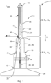
- the wind energy installation 2 has a tower 4 .
- the tower 4 has a plurality of wall elements 6 arranged one above the other. At least some, in particular all of the wall elements 6 have concrete or are made of it.
- the tower 4 has a lower section 8 .
- the lower section 8 extends from a lower end section 10 to a reference level 12.
- the tower 4 also has an upper section 14 which, starting from the reference level 12, extends to an upper end section 16.
- the reference level 12 divides the in 1 Tower 4 shown in such a way that a length h o of the upper section 14 corresponds to a length h u of the lower section 8 .
- the tower has an overall height h tot .
- the total height h tot is in particular in the range of 100 m to 220 m, with the in 1 tower shown has a total height h ges of 200 m.
- the reference height 12 corresponds in particular to a blade tip passage height 12 of a rotor blade of the wind turbine 2, not shown here.
- the wall elements 6 have a height hw of 3 m in particular.
- the wall elements 6 have an outer diameter d.
- the outer diameter d is essentially constant in the area of the upper section 14 .
- the outer diameter d of the wall elements 6 in the lower section 8 tapers from the lower end section 10 towards the reference level 12.
- the taper can be linear or, as in FIG 1 shown, in sections.
- the tower 4 is formed in the lower section 8 of at least sections of conical wall elements 6, which cause a gradual narrowing of the tower 4 in this section with increasing height.
- the outer diameter d of the wall elements 6 in the area of the lower end section 10 is, for example, 8 m to 9 m, in particular 8.5 m
- the wall elements 6 of the upper section 14 have an essentially constant outer diameter d, which is, for example, in the range of 4 m to 5 m, in particular 4.5 m.
- the tower also has a framework system 42 .
- the framework system 42 is arranged inside the tower 4 .
- the supporting framework system 42 is mechanically decoupled from the wall elements 6 .
- the supporting framework system 42 has a tension rod 44 which is fastened to at least one wall element 6 .
- the tie rod 44 is designed to mechanically decouple the framework system 42 from the corresponding wall element 6 to which it is connected.
- the framework system 42 has at least two spaced tension rods 44 .
- the adjacent tension rods 44 are at a distance from one another of, in particular, 20 m to 30 m.
- the tower 4 also has a neutral fiber 46 .
- the neutral fiber 46 extends essentially along a vertical longitudinal axis of the tower 4.
- the supporting framework system 42 is arranged coaxially with the neutral fiber 46.
- FIG. The framework system 42 is configured to accommodate a conductor path 48 and a cable path 50 .
- the truss system 42 can be set up to accommodate a platform, a lighting device or a lift.
- the tower 4 also has a tensioning device 28 .
- the clamping device has at least one clamping means 30, in particular a plurality of clamping means 30.
- the clamping device 28 with the clamping means 30 is designed to clamp the wall elements 6 .
- the clamping device 28 supports the tower 4 as to form a prestressed concrete tower.
- Several or all of the wall elements 6 of the upper section 14 each have a guide recess 32 .
- the clamping means 30 is movably guided in the guide recesses 32 in the upper section 14 .
- the clamping means 30 is guided in the lower section 8 at a distance from the wall elements 6 inside the tower 4 . Between the upper section 14 and the lower section 8 , the clamping means 30 emerges from the guide recesses 32 in an exit area 40 .
- the tower 4 has a foundation 36 .
- the foundation 36 adjoins the lower closure section 10 .
- the clamping means 30 is clamped to the foundation 36, in particular by means of a fixed anchor 38 concreted into the foundation 36.
- the clamping means 30 is also clamped to the upper closing section 16.
- a deflection adapter 41 is also provided within the tower 4 .
- the deflection adapter 41 is set up to deflect the clamping means 30 .
- the clamping means 30 runs essentially vertically in the area of the upper section 14, with the tower being placed here in the erected state, and in the area of the lower section 8 starting from the foundation 36 in the direction of the reference height 12 upwards and radially inwards. In this way, the clamping means 30 makes use of a leverage effect which results from the relevant arrangement and guidance.
- the lower section 8 has a total mass m u .
- the upper section 14 has a total mass mo .
- the mass m u essentially corresponds to the mass m o .
- the wall elements 6 of the lower section 8 have a first concrete material 22 .
- the wall elements 6 of the upper section 14 have a second concrete material 24 .
- the first concrete material 22 differs from the second concrete material 24 with regard to at least one material property 26.
- the first concrete material 22 is preferably a high-strength concrete material.
- the second concrete material 24 is preferably not a high-strength concrete material. In this respect, the second concrete material 24 typically has a lower strength and/or material quality than the first concrete material 22.
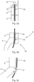
- FIGS. 2a to 2c show detailed representations of the in 1 areas of the tower highlighted by circles 4.
- Figure 2a shows the bracing of the tensioning means 30 and its guidance through the guide recesses 32 of the wall elements 6.
- the tensioning means 30 is braced in an upper region of the tower by means of a fixing means 34.
- Figure 2b shows the guidance of the clamping means 30 in the area of the reference height 12. In the upper wall element 6 shown, the clamping means 30 is in the guide recess 32 guided. Such guidance also takes place in the lower wall element 6 in the upper area of the wall element 6 , with the clamping means 30 now leaving the guide recess 32 in the lower area and being guided in the direction of the foundation 36 of the tower 4 inside the tower 4 .
- Figure 2c shows a deflection adapter 41 for deflecting the clamping means 30.
- the deflection adapter 41 is arranged inside the tower 4.
- FIG. In this respect, the clamping means 30 runs essentially vertically in the area of the upper section 14 and in the area of the lower section 8 starting from the foundation 36 in the direction of the reference height 12 upwards and radially inwards.
- FIG. 3 shows an alternative representation of a tower 4 according to the invention, which is based on the representation in 1 leans against How 3 it can be seen that the wall elements 6 in the upper section 14 have a wall thickness d o .
- the wall elements 6 in the lower section 8 have a wall thickness d u .
- the height profile H entered by means of a schematic arrow representation.
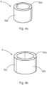
- FIGS. 4a and 4b show exemplary wall elements 6.
- the wall element 6 is formed by the half-shells 52a and 52b.
- Such a two-part design of the wall elements 6 is particularly advantageous with smaller outside diameters d.
- the wall element 6 has a total of three half-shells 52a, 52b, 52c.
- Such a three-part design of the wall element 6 is particularly suitable for larger diameters d.
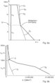
- Figure 5a shows two diagrams, a first diagram showing a mass distribution m 1 for a tower 4 according to the invention in a soft-soft design.
- a second diagram shows a mass distribution m 2 of a tower from the prior art which has a soft-stiff design.
- the mass is plotted against the height of a tower which has a total height h tot , which is divided into a height h o of the upper section 14 and a height h u of the lower section 8 .
- the tower according to the invention has a mass distribution m 1 which is largely constant over the height of the tower.
- the upper section 14 and the lower section 8 have substantially the same mass.
- the mass distribution of which is represented here by m 2 a substantial part of the mass is concentrated on the lower section 8 and decreases with increasing height.
- Figure 5b shows two diagrams, a first diagram showing a mass distribution m r for a tower 4 according to the invention in a soft-resonance design.
- a second diagram shows a mass distribution m 2 of a tower from the prior art, which has a soft-stiff design.
- the mass is plotted against the height of a tower which has a total height h tot of 200 m, which is divided into a height h o of the upper section 14 and a height h u of the lower section 8 .
- the mass distribution m r of the soft resonance tower 4 according to the invention is largely constant over the height in the upper section 14 and increases in the lower section 8 with decreasing height.
- Figure 6a shows a flexural rigidity distribution S 1 of a tower 4 according to the invention in a soft-soft design, which is compared with a flexural rigidity distribution S 2 of a tower from the prior art (soft-stiff design).
- the tower 4 according to the invention has a more constant bending stiffness distribution S 1 than the tower S 2 previously known from the prior art.
- the flexural rigidity S o of the tower 4 according to the invention is largely constant or increases only slightly, viewed from the top of the tower downwards. Overall, the flexural rigidity S o is greater than in known towers with a flexural rigidity distribution S 2 .
- the flexural rigidity S u of the lower section 8 of the tower 4 increases to a greater extent in relation to a height interval, but the increase and also the total value of the flexural rigidity S u of the lower section 8 are below those of from a standing position towers known in the art, shown here as S 2 .
- Figure 6b shows a flexural rigidity distribution S r of a tower 4 according to the invention in a soft resonance design, which is compared with a flexural rigidity distribution S 2 of a tower from the prior art (soft-stiff design).
- the tower 4 designed for soft resonance according to the invention has a more constant bending stiffness distribution S r than the tower S 2 previously known from the prior art.
- the flexural rigidity S r is largely constant in the case of the tower 4 according to the invention.
- the flexural rigidity S r is only greater in the upper 10% to 15% of the total height h tot than in known soft-stiff towers with a flexural rigidity distribution S 2 and is otherwise lower.
- the flexural rigidity S r of the lower section 8 of the tower 4 according to the invention increases with decreasing height, but the increase and also the total value of the flexural rigidity S r of the lower section 8 are significantly below those of the prior art Towers, shown here with S 2 .
- the flexural rigidity S r near the ground is, for example, a maximum of approximately 5,000,000 MNm 2 in the case of one from the prior art well-known soft-stiff tower with the bending stiffness distribution S 2 near the ground up to about 20,000,000 MNm 2 .
- FIG. 7 shows a so-called Campbell diagram in which a tower natural frequency is plotted against a rotor speed of a wind turbine.
- the natural frequency E is entered in the form of a line 64 for a tower according to the invention.
- the natural frequency E corresponds to a soft-soft design of the tower.
- a further tower natural frequency 62 is shown in the diagram as an example, which corresponds to a soft-stiff design of the tower. Natural frequencies above a soft/stiff transition line 70 are to be assigned to the soft-stiff range and natural frequencies below the soft/stiff transition line 70 to the soft-soft range.
- the rotor of the wind turbine is operated in an operating speed range 60 between a lower rotor speed 72 and an upper rotor speed 74 .
- the rotor has a simple blade excitation frequency 66, which is shown as a straight line.
- the point of intersection of the straight line of the blade excitation frequency 66 with the upper rotor speed 74 determines the horizontal position of the soft/stiff transition line 70.
- a rotor speed curve 68 also shown corresponds to the triple excitation, which is also referred to as blade passage excitation.
- FIG. 8 shows schematically the tower 4 according to the invention.
- the tower 4 has a neutral axis 46 .
- the supporting framework system 42 is arranged in the area of the neutral axis 46, in particular coaxially thereto.
- 9 shows a selection of wall elements 6 schematically.
- the wall elements 6 are connected by means of vertical fixings 54 .
- 10 12 shows an alternative exemplary embodiment of a tower 4 according to the invention, which has a framework system 72 in the form of a “tower-in-tower” arrangement.
- the framework system 72 is secured against displacement relative to the tower, but is not attached to the side of it.
- segments of the truss system 72 are provided on a floor platform and the truss system is then assembled from top to bottom.
- the supporting structure system 72 is connected to the tower 4 via a supporting structure system suspension 74 which is arranged in an upper tower area and is suspended from the supporting structure system suspension 74 .
Landscapes
- Engineering & Computer Science (AREA)
- Life Sciences & Earth Sciences (AREA)
- Sustainable Development (AREA)
- Sustainable Energy (AREA)
- Chemical & Material Sciences (AREA)
- Combustion & Propulsion (AREA)
- Mechanical Engineering (AREA)
- General Engineering & Computer Science (AREA)
- Power Engineering (AREA)
- Wind Motors (AREA)
Applications Claiming Priority (1)
| Application Number | Priority Date | Filing Date | Title |
|---|---|---|---|
| DE102022100725.1A DE102022100725A1 (de) | 2022-01-13 | 2022-01-13 | Turm für eine Windenergieanlage und betreffende Windenergieanlage |
Publications (1)
| Publication Number | Publication Date |
|---|---|
| EP4212720A1 true EP4212720A1 (fr) | 2023-07-19 |
Family
ID=84981032
Family Applications (1)
| Application Number | Title | Priority Date | Filing Date |
|---|---|---|---|
| EP23151574.3A Withdrawn EP4212720A1 (fr) | 2022-01-13 | 2023-01-13 | Tour pour une éolienne et éolienne correspondante |
Country Status (2)
| Country | Link |
|---|---|
| EP (1) | EP4212720A1 (fr) |
| DE (1) | DE102022100725A1 (fr) |
Cited By (4)
| Publication number | Priority date | Publication date | Assignee | Title |
|---|---|---|---|---|
| CN114526200A (zh) * | 2022-02-23 | 2022-05-24 | 上海电气风电集团股份有限公司 | 模块化风电混凝土塔架、风力发电系统以及制作方法 |
| EP4481194A1 (fr) * | 2023-06-21 | 2024-12-25 | Nordex Energy Spain, S.A.U. | Dispositif de retenue d'un élément post-tendeur d'une tour d'éolienne, système de guidage d'une tour d'éolienne, tour d'éolienne |
| EP4497944A1 (fr) * | 2023-07-27 | 2025-01-29 | Bettels Betonfertigteile GmbH | Segment de tour pour une tour d'une éolienne ainsi que tour associée |
| CN119508158A (zh) * | 2025-01-21 | 2025-02-25 | 湖南科技大学 | 风电机组混凝土塔筒安全监测、预警与评估方法 |
Citations (8)
| Publication number | Priority date | Publication date | Assignee | Title |
|---|---|---|---|---|
| EP1606514B1 (fr) * | 2003-03-19 | 2007-11-07 | Vestas Wind System A/S | Procede de construction de grandes tours destinees a des turbines eoliennes |
| EP1008747B1 (fr) * | 1998-12-08 | 2008-06-04 | Franz Mitsch | Amortisseur de vibration pour éoliennes |
| WO2013098086A1 (fr) * | 2011-12-30 | 2013-07-04 | Werner Rolf J | Structure porteuse en forme de tour |
| EP2764185A1 (fr) * | 2011-08-26 | 2014-08-13 | Max Bögl Wind AG | Procédé destiné à construire un mât et mât ainsi obtenu |
| EP3211154A1 (fr) * | 2016-02-26 | 2017-08-30 | Acciona Windpower S.a. | Procédé pour un mat de éolienne en béton et mat de éolienne en béton |
| EP3048295B1 (fr) * | 2015-01-26 | 2018-08-29 | Senvion GmbH | Procede de montage d'une eolienne et eolienne |
| WO2019076586A1 (fr) * | 2017-10-19 | 2019-04-25 | Innogy Se | Fondation souple pour bâtiments en mer |
| EP3495589A1 (fr) * | 2017-12-06 | 2019-06-12 | Senvion GmbH | Tour d'une éolienne, procédé de construction d'une tour d'une éolienne, éolienne |
Family Cites Families (6)
| Publication number | Priority date | Publication date | Assignee | Title |
|---|---|---|---|---|
| DE102011076941A1 (de) | 2010-06-03 | 2011-12-29 | Suzlon Energy Gmbh | Turm für eine Windturbine |
| DE102011102473A1 (de) | 2011-05-25 | 2012-11-29 | Philipp Wagner | Mehrschalige Turmkonstruktion für Windenergieanlagen |
| CN103399971B (zh) | 2013-05-09 | 2016-08-24 | 南车株洲电力机车研究所有限公司 | 一种基于机械能能量守恒的风机塔架固有频率分析方法 |
| DE102018108945A1 (de) | 2018-04-16 | 2019-10-17 | Wobben Properties Gmbh | Verfahren zum Errichten eines Windenergieanlagen-Turms |
| CN113056607A (zh) | 2018-09-28 | 2021-06-29 | 通用电气公司 | 用于基于风向而制造风力涡轮塔架结构的方法 |
| CN113062649B (zh) | 2021-03-31 | 2022-01-18 | 重庆大学 | 一种基于参数设计计算的预应力调谐质量阻尼器安装方法 |
-
2022
- 2022-01-13 DE DE102022100725.1A patent/DE102022100725A1/de not_active Ceased
-
2023
- 2023-01-13 EP EP23151574.3A patent/EP4212720A1/fr not_active Withdrawn
Patent Citations (8)
| Publication number | Priority date | Publication date | Assignee | Title |
|---|---|---|---|---|
| EP1008747B1 (fr) * | 1998-12-08 | 2008-06-04 | Franz Mitsch | Amortisseur de vibration pour éoliennes |
| EP1606514B1 (fr) * | 2003-03-19 | 2007-11-07 | Vestas Wind System A/S | Procede de construction de grandes tours destinees a des turbines eoliennes |
| EP2764185A1 (fr) * | 2011-08-26 | 2014-08-13 | Max Bögl Wind AG | Procédé destiné à construire un mât et mât ainsi obtenu |
| WO2013098086A1 (fr) * | 2011-12-30 | 2013-07-04 | Werner Rolf J | Structure porteuse en forme de tour |
| EP3048295B1 (fr) * | 2015-01-26 | 2018-08-29 | Senvion GmbH | Procede de montage d'une eolienne et eolienne |
| EP3211154A1 (fr) * | 2016-02-26 | 2017-08-30 | Acciona Windpower S.a. | Procédé pour un mat de éolienne en béton et mat de éolienne en béton |
| WO2019076586A1 (fr) * | 2017-10-19 | 2019-04-25 | Innogy Se | Fondation souple pour bâtiments en mer |
| EP3495589A1 (fr) * | 2017-12-06 | 2019-06-12 | Senvion GmbH | Tour d'une éolienne, procédé de construction d'une tour d'une éolienne, éolienne |
Cited By (5)
| Publication number | Priority date | Publication date | Assignee | Title |
|---|---|---|---|---|
| CN114526200A (zh) * | 2022-02-23 | 2022-05-24 | 上海电气风电集团股份有限公司 | 模块化风电混凝土塔架、风力发电系统以及制作方法 |
| EP4481194A1 (fr) * | 2023-06-21 | 2024-12-25 | Nordex Energy Spain, S.A.U. | Dispositif de retenue d'un élément post-tendeur d'une tour d'éolienne, système de guidage d'une tour d'éolienne, tour d'éolienne |
| WO2024261247A1 (fr) * | 2023-06-21 | 2024-12-26 | Nordex Energy Spain, S.A.U | Dispositif de retenue d'un élément de post-tension d'un système de post-tension d'une tour d'une éolienne, système de guidage d'une tour d'une éolienne, tour d'une éolienne et procédé de post-tension d'une tour d'une éolienne |
| EP4497944A1 (fr) * | 2023-07-27 | 2025-01-29 | Bettels Betonfertigteile GmbH | Segment de tour pour une tour d'une éolienne ainsi que tour associée |
| CN119508158A (zh) * | 2025-01-21 | 2025-02-25 | 湖南科技大学 | 风电机组混凝土塔筒安全监测、预警与评估方法 |
Also Published As
| Publication number | Publication date |
|---|---|
| DE102022100725A1 (de) | 2023-07-13 |
Similar Documents
| Publication | Publication Date | Title |
|---|---|---|
| EP4212720A1 (fr) | Tour pour une éolienne et éolienne correspondante | |
| EP3092357B1 (fr) | Ensemble comprenant une fondation en béton et une tour et procédé d'érection d'une tour | |
| EP2764185B1 (fr) | Procédé destiné à construire un mât, mât ainsi obtenu | |
| EP2182209B1 (fr) | Construction de tour hybride | |
| EP2009202B1 (fr) | Tour d'énergie éolienne | |
| EP2932095B1 (fr) | Élément de transition destiné à être disposé entre des portions exécutées différemment d'une tour d'éolienne et tour d'éolienne équipée dudit élément de transition | |
| EP3092358B1 (fr) | Éolienne pourvue d'un mât et d'une embase composée de plusieurs segments | |
| WO2014016166A1 (fr) | Mât modulaire d'une éolienne | |
| EP3477099B1 (fr) | Tour pourvue d'éléments adaptateurs en acier coniques | |
| EP3464754B1 (fr) | Dispositif de montée pour la réalisation d'un mouvement par rapport à un mât et procédé de fabrication d'un mât | |
| EP3781811B1 (fr) | Procédé permettant d'ériger une tour d'éolienne | |
| EP3853472A1 (fr) | Segment de tour d'éolienne pour tour d'éolienne et procédé | |
| EP3891386B1 (fr) | Procédé pour réaliser un préserrage du mât d'une éolienne | |
| WO2015110580A1 (fr) | Mât haubané pour une éolienne ayant une résistance à la torsion élevée | |
| EP3597829B1 (fr) | Renfort de fondations pour ouvrages en mer | |
| EP3658770B1 (fr) | Segment annulaire de tour en acier pour éoliennes et procédé | |
| EP3956561B1 (fr) | Section de tour et procédé pour la construction d'une tour | |
| DE102023135717A1 (de) | Teleskopierbarer Gittermastturm und Verfahren zum Heben eines teleskopierbaren Gittermastturms | |
| WO2004076781A1 (fr) | Dispositif pour eriger une eolienne | |
| DE2742417A1 (de) | Rohrmast | |
| EP4001553B1 (fr) | Guidage de mât et procede de fonctionnement d'une construction provisoire avec un mât utilisant un tel guidage de mât | |
| EP4524393A1 (fr) | Tour pour une éolienne, éolienne et procédé de fabrication | |
| EP4339457A1 (fr) | Procédé de construction et/ou de transformation d'une éolienne, utilisation d'une tour d'une éolienne et éolienne | |
| CH714681A2 (de) | Freileitungsmast bestehend aus einem oder zwei Einzelmasten. | |
| DE29805693U1 (de) | Hochspannungsfreileitungsmast |
Legal Events
| Date | Code | Title | Description |
|---|---|---|---|
| PUAI | Public reference made under article 153(3) epc to a published international application that has entered the european phase |
Free format text: ORIGINAL CODE: 0009012 |
|
| STAA | Information on the status of an ep patent application or granted ep patent |
Free format text: STATUS: THE APPLICATION HAS BEEN PUBLISHED |
|
| AK | Designated contracting states |
Kind code of ref document: A1 Designated state(s): AL AT BE BG CH CY CZ DE DK EE ES FI FR GB GR HR HU IE IS IT LI LT LU LV MC ME MK MT NL NO PL PT RO RS SE SI SK SM TR |
|
| STAA | Information on the status of an ep patent application or granted ep patent |
Free format text: STATUS: REQUEST FOR EXAMINATION WAS MADE |
|
| 17P | Request for examination filed |
Effective date: 20240119 |
|
| RBV | Designated contracting states (corrected) |
Designated state(s): AL AT BE BG CH CY CZ DE DK EE ES FI FR GB GR HR HU IE IS IT LI LT LU LV MC ME MK MT NL NO PL PT RO RS SE SI SK SM TR |
|
| STAA | Information on the status of an ep patent application or granted ep patent |
Free format text: STATUS: EXAMINATION IS IN PROGRESS |
|
| 17Q | First examination report despatched |
Effective date: 20240516 |
|
| STAA | Information on the status of an ep patent application or granted ep patent |
Free format text: STATUS: THE APPLICATION IS DEEMED TO BE WITHDRAWN |
|
| 18D | Application deemed to be withdrawn |
Effective date: 20241026 |