EP4212837B1 - Procédé de mesure de température de surface, dispositif de mesure de température de surface, procédé de fabrication de tôle d'acier galvanisée à chaud, et installation de fabrication de tôle d'acier galvanisée à chaud - Google Patents
Procédé de mesure de température de surface, dispositif de mesure de température de surface, procédé de fabrication de tôle d'acier galvanisée à chaud, et installation de fabrication de tôle d'acier galvanisée à chaud Download PDFInfo
- Publication number
- EP4212837B1 EP4212837B1 EP21885660.7A EP21885660A EP4212837B1 EP 4212837 B1 EP4212837 B1 EP 4212837B1 EP 21885660 A EP21885660 A EP 21885660A EP 4212837 B1 EP4212837 B1 EP 4212837B1
- Authority
- EP
- European Patent Office
- Prior art keywords
- steel sheet
- hot
- emissivity
- plated steel
- light amount
- Prior art date
- Legal status (The legal status is an assumption and is not a legal conclusion. Google has not performed a legal analysis and makes no representation as to the accuracy of the status listed.)
- Active
Links
Images








Classifications
-
- G—PHYSICS
- G01—MEASURING; TESTING
- G01J—MEASUREMENT OF INTENSITY, VELOCITY, SPECTRAL CONTENT, POLARISATION, PHASE OR PULSE CHARACTERISTICS OF INFRARED, VISIBLE OR ULTRAVIOLET LIGHT; COLORIMETRY; RADIATION PYROMETRY
- G01J5/00—Radiation pyrometry, e.g. infrared or optical thermometry
- G01J5/0003—Radiation pyrometry, e.g. infrared or optical thermometry for sensing the radiant heat transfer of samples, e.g. emittance meter
-
- C—CHEMISTRY; METALLURGY
- C23—COATING METALLIC MATERIAL; COATING MATERIAL WITH METALLIC MATERIAL; CHEMICAL SURFACE TREATMENT; DIFFUSION TREATMENT OF METALLIC MATERIAL; COATING BY VACUUM EVAPORATION, BY SPUTTERING, BY ION IMPLANTATION OR BY CHEMICAL VAPOUR DEPOSITION, IN GENERAL; INHIBITING CORROSION OF METALLIC MATERIAL OR INCRUSTATION IN GENERAL
- C23C—COATING METALLIC MATERIAL; COATING MATERIAL WITH METALLIC MATERIAL; SURFACE TREATMENT OF METALLIC MATERIAL BY DIFFUSION INTO THE SURFACE, BY CHEMICAL CONVERSION OR SUBSTITUTION; COATING BY VACUUM EVAPORATION, BY SPUTTERING, BY ION IMPLANTATION OR BY CHEMICAL VAPOUR DEPOSITION, IN GENERAL
- C23C2/00—Hot-dipping or immersion processes for applying the coating material in the molten state without affecting the shape; Apparatus therefor
- C23C2/04—Hot-dipping or immersion processes for applying the coating material in the molten state without affecting the shape; Apparatus therefor characterised by the coating material
- C23C2/06—Zinc or cadmium or alloys based thereon
-
- C—CHEMISTRY; METALLURGY
- C23—COATING METALLIC MATERIAL; COATING MATERIAL WITH METALLIC MATERIAL; CHEMICAL SURFACE TREATMENT; DIFFUSION TREATMENT OF METALLIC MATERIAL; COATING BY VACUUM EVAPORATION, BY SPUTTERING, BY ION IMPLANTATION OR BY CHEMICAL VAPOUR DEPOSITION, IN GENERAL; INHIBITING CORROSION OF METALLIC MATERIAL OR INCRUSTATION IN GENERAL
- C23C—COATING METALLIC MATERIAL; COATING MATERIAL WITH METALLIC MATERIAL; SURFACE TREATMENT OF METALLIC MATERIAL BY DIFFUSION INTO THE SURFACE, BY CHEMICAL CONVERSION OR SUBSTITUTION; COATING BY VACUUM EVAPORATION, BY SPUTTERING, BY ION IMPLANTATION OR BY CHEMICAL VAPOUR DEPOSITION, IN GENERAL
- C23C2/00—Hot-dipping or immersion processes for applying the coating material in the molten state without affecting the shape; Apparatus therefor
- C23C2/34—Hot-dipping or immersion processes for applying the coating material in the molten state without affecting the shape; Apparatus therefor characterised by the shape of the material to be treated
- C23C2/36—Elongated material
- C23C2/40—Plates; Strips
-
- C—CHEMISTRY; METALLURGY
- C23—COATING METALLIC MATERIAL; COATING MATERIAL WITH METALLIC MATERIAL; CHEMICAL SURFACE TREATMENT; DIFFUSION TREATMENT OF METALLIC MATERIAL; COATING BY VACUUM EVAPORATION, BY SPUTTERING, BY ION IMPLANTATION OR BY CHEMICAL VAPOUR DEPOSITION, IN GENERAL; INHIBITING CORROSION OF METALLIC MATERIAL OR INCRUSTATION IN GENERAL
- C23C—COATING METALLIC MATERIAL; COATING MATERIAL WITH METALLIC MATERIAL; SURFACE TREATMENT OF METALLIC MATERIAL BY DIFFUSION INTO THE SURFACE, BY CHEMICAL CONVERSION OR SUBSTITUTION; COATING BY VACUUM EVAPORATION, BY SPUTTERING, BY ION IMPLANTATION OR BY CHEMICAL VAPOUR DEPOSITION, IN GENERAL
- C23C2/00—Hot-dipping or immersion processes for applying the coating material in the molten state without affecting the shape; Apparatus therefor
- C23C2/50—Controlling or regulating the coating processes
-
- C—CHEMISTRY; METALLURGY
- C23—COATING METALLIC MATERIAL; COATING MATERIAL WITH METALLIC MATERIAL; CHEMICAL SURFACE TREATMENT; DIFFUSION TREATMENT OF METALLIC MATERIAL; COATING BY VACUUM EVAPORATION, BY SPUTTERING, BY ION IMPLANTATION OR BY CHEMICAL VAPOUR DEPOSITION, IN GENERAL; INHIBITING CORROSION OF METALLIC MATERIAL OR INCRUSTATION IN GENERAL
- C23C—COATING METALLIC MATERIAL; COATING MATERIAL WITH METALLIC MATERIAL; SURFACE TREATMENT OF METALLIC MATERIAL BY DIFFUSION INTO THE SURFACE, BY CHEMICAL CONVERSION OR SUBSTITUTION; COATING BY VACUUM EVAPORATION, BY SPUTTERING, BY ION IMPLANTATION OR BY CHEMICAL VAPOUR DEPOSITION, IN GENERAL
- C23C2/00—Hot-dipping or immersion processes for applying the coating material in the molten state without affecting the shape; Apparatus therefor
- C23C2/50—Controlling or regulating the coating processes
- C23C2/52—Controlling or regulating the coating processes with means for measuring or sensing
-
- C—CHEMISTRY; METALLURGY
- C23—COATING METALLIC MATERIAL; COATING MATERIAL WITH METALLIC MATERIAL; CHEMICAL SURFACE TREATMENT; DIFFUSION TREATMENT OF METALLIC MATERIAL; COATING BY VACUUM EVAPORATION, BY SPUTTERING, BY ION IMPLANTATION OR BY CHEMICAL VAPOUR DEPOSITION, IN GENERAL; INHIBITING CORROSION OF METALLIC MATERIAL OR INCRUSTATION IN GENERAL
- C23C—COATING METALLIC MATERIAL; COATING MATERIAL WITH METALLIC MATERIAL; SURFACE TREATMENT OF METALLIC MATERIAL BY DIFFUSION INTO THE SURFACE, BY CHEMICAL CONVERSION OR SUBSTITUTION; COATING BY VACUUM EVAPORATION, BY SPUTTERING, BY ION IMPLANTATION OR BY CHEMICAL VAPOUR DEPOSITION, IN GENERAL
- C23C2/00—Hot-dipping or immersion processes for applying the coating material in the molten state without affecting the shape; Apparatus therefor
- C23C2/50—Controlling or regulating the coating processes
- C23C2/52—Controlling or regulating the coating processes with means for measuring or sensing
- C23C2/526—Controlling or regulating the coating processes with means for measuring or sensing for visually inspecting the surface quality of the substrate
-
- G—PHYSICS
- G01—MEASURING; TESTING
- G01J—MEASUREMENT OF INTENSITY, VELOCITY, SPECTRAL CONTENT, POLARISATION, PHASE OR PULSE CHARACTERISTICS OF INFRARED, VISIBLE OR ULTRAVIOLET LIGHT; COLORIMETRY; RADIATION PYROMETRY
- G01J5/00—Radiation pyrometry, e.g. infrared or optical thermometry
- G01J5/0022—Radiation pyrometry, e.g. infrared or optical thermometry for sensing the radiation of moving bodies
-
- G—PHYSICS
- G01—MEASURING; TESTING
- G01J—MEASUREMENT OF INTENSITY, VELOCITY, SPECTRAL CONTENT, POLARISATION, PHASE OR PULSE CHARACTERISTICS OF INFRARED, VISIBLE OR ULTRAVIOLET LIGHT; COLORIMETRY; RADIATION PYROMETRY
- G01J5/00—Radiation pyrometry, e.g. infrared or optical thermometry
- G01J5/02—Constructional details
- G01J5/08—Optical arrangements
- G01J5/0893—Arrangements to attach devices to a pyrometer, i.e. attaching an optical interface; Spatial relative arrangement of optical elements, e.g. folded beam path
-
- G—PHYSICS
- G01—MEASURING; TESTING
- G01J—MEASUREMENT OF INTENSITY, VELOCITY, SPECTRAL CONTENT, POLARISATION, PHASE OR PULSE CHARACTERISTICS OF INFRARED, VISIBLE OR ULTRAVIOLET LIGHT; COLORIMETRY; RADIATION PYROMETRY
- G01J5/00—Radiation pyrometry, e.g. infrared or optical thermometry
- G01J5/02—Constructional details
- G01J5/08—Optical arrangements
- G01J5/0896—Optical arrangements using a light source, e.g. for illuminating a surface
-
- G—PHYSICS
- G01—MEASURING; TESTING
- G01J—MEASUREMENT OF INTENSITY, VELOCITY, SPECTRAL CONTENT, POLARISATION, PHASE OR PULSE CHARACTERISTICS OF INFRARED, VISIBLE OR ULTRAVIOLET LIGHT; COLORIMETRY; RADIATION PYROMETRY
- G01J5/00—Radiation pyrometry, e.g. infrared or optical thermometry
- G01J5/10—Radiation pyrometry, e.g. infrared or optical thermometry using electric radiation detectors
-
- G—PHYSICS
- G01—MEASURING; TESTING
- G01J—MEASUREMENT OF INTENSITY, VELOCITY, SPECTRAL CONTENT, POLARISATION, PHASE OR PULSE CHARACTERISTICS OF INFRARED, VISIBLE OR ULTRAVIOLET LIGHT; COLORIMETRY; RADIATION PYROMETRY
- G01J5/00—Radiation pyrometry, e.g. infrared or optical thermometry
- G01J5/48—Thermography; Techniques using wholly visual means
-
- G—PHYSICS
- G01—MEASURING; TESTING
- G01J—MEASUREMENT OF INTENSITY, VELOCITY, SPECTRAL CONTENT, POLARISATION, PHASE OR PULSE CHARACTERISTICS OF INFRARED, VISIBLE OR ULTRAVIOLET LIGHT; COLORIMETRY; RADIATION PYROMETRY
- G01J5/00—Radiation pyrometry, e.g. infrared or optical thermometry
- G01J5/70—Passive compensation of pyrometer measurements, e.g. using ambient temperature sensing or sensing of temperature within housing
-
- G—PHYSICS
- G01—MEASURING; TESTING
- G01J—MEASUREMENT OF INTENSITY, VELOCITY, SPECTRAL CONTENT, POLARISATION, PHASE OR PULSE CHARACTERISTICS OF INFRARED, VISIBLE OR ULTRAVIOLET LIGHT; COLORIMETRY; RADIATION PYROMETRY
- G01J5/00—Radiation pyrometry, e.g. infrared or optical thermometry
- G01J5/80—Calibration
- G01J5/802—Calibration by correcting for emissivity
-
- G—PHYSICS
- G01—MEASURING; TESTING
- G01J—MEASUREMENT OF INTENSITY, VELOCITY, SPECTRAL CONTENT, POLARISATION, PHASE OR PULSE CHARACTERISTICS OF INFRARED, VISIBLE OR ULTRAVIOLET LIGHT; COLORIMETRY; RADIATION PYROMETRY
- G01J5/00—Radiation pyrometry, e.g. infrared or optical thermometry
- G01J2005/0074—Radiation pyrometry, e.g. infrared or optical thermometry having separate detection of emissivity
-
- G—PHYSICS
- G01—MEASURING; TESTING
- G01J—MEASUREMENT OF INTENSITY, VELOCITY, SPECTRAL CONTENT, POLARISATION, PHASE OR PULSE CHARACTERISTICS OF INFRARED, VISIBLE OR ULTRAVIOLET LIGHT; COLORIMETRY; RADIATION PYROMETRY
- G01J5/00—Radiation pyrometry, e.g. infrared or optical thermometry
- G01J2005/0077—Imaging
Definitions
- the present invention relates to a surface temperature measuring method, a surface temperature measuring apparatus, a hot-dip zinc plated steel sheet manufacturing method, and a hot-dip zinc plated steel sheet manufacturing equipment.
- CGL hot-dip galvanizing line
- temperature control is a very important work in production of materials and quality control of plating.
- an excessively high steel sheet temperature causes occurrence of powdering while an excessively low steel sheet temperature causes insufficient alloying.
- an excessively high steel sheet temperature in the high- strength material, causes coarsening of the crystal grain size, leading to deterioration of material characteristics.
- CGL is required to achieve very strict temperature control.
- examples of a method of heating the steel sheet include electromagnetic induction heating (hereinafter, denoted as IH) and heat transfer by radiant heat.
- examples of the method of the temperature control include a method of calculating the temperature of the steel sheet immediately after heating by heat transfer calculation or electromagnetic field simulation based on an output of IH or direct heating, the steel sheet conveyance speed, the sheet size, and the temperature of the molten zinc pod.
- Proposed methods of directly measuring the temperature of the steel sheet include methods such as a radiation thermometry and a temperature measurement roll method (refer to Non Patent Literature 1).
- a radiation thermometry and a temperature measurement roll method
- the emissivity of the steel sheet surface greatly fluctuates depending on the progress of alloying, leading to an occurrence of a large measurement error in a radiation thermometer that presets the emissivity as a fixed value.
- several efforts have been made as measures against the problem of emissivity setting necessary for the radiation thermometry.
- thermometer being a multiple reflection radiation thermometer utilizing a rule that the emissivity approaches 1 by multiple reflection of radiation light.
- thermometers developed, such as a wedge type radiation thermometer (refer to Patent Literature 1) using multiple reflection generated in a gap between a roll and a steel sheet on the assumption that the roll and the steel sheet are isothermal, and a bowl type radiation thermometer (refer to Patent Literature 2) in which a concave member having a high reflectance such as a member with gold plating is brought close to a measurement object.
- JP 2020 034430 A describes a surface temperature measurement based on acquired specular and diffuse reflection light amounts.
- the progress of the alloying reaction varies depending on the type and size of the steel sheet and the conveyance conditions.
- the target temperature of the steel sheet is about 450°C to 550°C.
- the emissivity of the surface of the steel sheet changes to the value about 0.2 to 0.7 before and after alloying. This corresponds to a difference of 60°C or more in terms of temperature, which leads to a failure of accurate measurement of the temperature of the steel sheet.
- the wedge type radiation thermometer is not applicable to the time immediately after heating having temperature measurement needs, similarly to the temperature measuring roll.
- the bowl type radiation thermometer also needs to make a lift-off distance of the passline very small.
- fluctuation of the passline cannot be suppressed by the roll after the molten zinc adhesion in the CGL, making it difficult to apply the bowl type radiation thermometer due to the lift-off distance.
- the method of estimating the emissivity by estimating the integrating sphere reflectance has been used in an application example in other cold rolled steel sheet processes.
- the diffusibility of the surface of the steel sheet is very high in the alloying process, lowering the estimation accuracy of the integrating sphere reflectance and the emissivity.
- the TRACE thermometer which is not based on a physical model, is susceptible to unexpected disturbance and phenomenon, and thus has a limited practicability.
- the present invention has been made in view of the above problems and aims to provide a surface temperature measuring method and a surface temperature measuring apparatus capable of accurately measuring a surface temperature of a measurement object regardless of a fluctuation in emissivity of the surface of the measurement object.
- the present invention also aims to provide a hot-dip zinc plated steel sheet manufacturing method and a manufacturing equipment capable of manufacturing a hot-dip zinc plated steel sheet with high yield by accurately measuring a steel sheet temperature in a hot-dip galvanizing line regardless of an alloying process.
- the invention provides a surface temperature measuring method according to claim 1.
- the emissivity calculating step is executed in a case where a specular reflection light amount acquired in the second imaging step is less than a predetermined value, and a fixed value is used as the emissivity in the temperature measurement step in a case where the specular reflection light amount acquired in the second imaging step is a predetermined value or more.
- each of the second imaging step and the third imaging step includes a step of correcting the specular reflection light amount and the diffuse reflection light amount by subtracting the radiation light amount acquired in the first imaging step.
- the first imaging step, the second imaging step, and the third imaging step include a step of receiving light using a light receiving element having a plurality of visual fields to which acquisition ranges of the radiation light amount, the specular reflection light amount, and the diffuse reflection light amount are assigned in a conveyance direction of the measurement object.
- the measurement object is a hot-dip zinc plated steel sheet.
- the invention further provides a surface temperature measuring apparatus according to claim 5.
- the measurement object is a hot-dip zinc plated steel sheet.
- a hot-dip zinc plated steel sheet manufacturing method includes manufacturing steps of manufacturing a hot-dip zinc plated steel sheet, the manufacturing steps of manufacturing the hot-dip zinc plated steel sheet includes: a temperature measurement step of measuring a surface temperature of the hot-dip zinc plated steel sheet by the surface temperature measuring method according to the present invention; and a step of controlling manufacturing conditions in the manufacturing steps by using the surface temperature measured in the temperature measurement step.
- a hot-dip zinc plated steel sheet manufacturing equipment includes: the surface temperature measuring apparatus according to the present invention; and an equipment that manufactures a hot-dip zinc plated steel sheet based on a surface temperature of a hot-dip zinc plated steel sheet measured by the surface temperature measuring apparatus.
- the surface temperature of the measurement object can be accurately measured regardless of the fluctuation in the emissivity of the surface of the measurement object.
- the hot-dip zinc plated steel sheet manufacture method and manufacturing equipment according to the present invention it is possible to accurately measure the temperature of a steel sheet in a hot-dip galvanizing line regardless of an alloying process, enabling manufacture of a hot-dip zinc plated steel sheet with high yield.
- the radiation thermometry is a method of calculating the surface temperature of a measurement object using a measured radiation amount and a preset emissivity by using a rule that the radiation amount of the measurement object is theoretically determined by the temperature and the emissivity.
- the emissivity of the measurement object changes within a range of 0 to 1 depending on the state and shape of the surface of the measurement object. Therefore, in order to accurately measure the surface temperature of the measurement object, the emissivity of the measurement object needs to be set to a correct value. Accordingly, many commonly used radiation thermometers preliminarily measure the emissivity of the measurement object or use a known emissivity for the measurement object to preset the emissivity as a fixed value.
- the radiation light amount is measured, and the surface temperature of the measurement object is obtained from a standard curve.
- Examples of the method of measuring the emissivity described herein include a method in which a black body paint having a known emissivity is applied to measure a radiation light amount ratio with respect to a measurement target site, and a method in which a surface temperature value obtained by another measuring method such as a thermocouple is theoretically converted into a radiation amount for comparison.
- the steel sheet surface can take a variety of states, including a state where the surface of the steel sheet is close to a mirror surface far from being alloyed and a state where the alloying progresses to be close to a rough surface. Therefore, presetting the emissivity as a fixed value will inevitably lead to occurrence of a large deviation from the actual emissivity.
- the progress of the degree of alloying greatly changes depending on components and manufacturing conditions, making it difficult to predict the surface state and the emissivity in advance.
- the inventors have studied techniques of correctly estimating the emissivity in real time with respect to the fluctuating surface property of the measurement object and converting the radiance into the temperature with the estimated emissivity.
- a method of estimating the emissivity focuses on the Kirchhoff's law in which the sum of the emissivity and the integrating sphere reflectance is 1.
- Patent Literature 3 describes a method of calculating an integrating sphere reflectance based on reflection distribution information, although it is difficult to accurately measure a parameter of a spread of a specular reflection component that greatly contributes to accuracy, leading to failure of acquisition of sufficient accuracy. Still, the reflection characteristic of the measurement object has a close physical relationship with the emissivity, and thus, is considered to be an important clue in estimating the emissivity even for a surface that changes in the course of alloying the hot-dip zinc plated steel sheet.
- the inventors of the present invention have focused on the fact that reflection characteristics are typically expressed by the sum of specular reflection and diffuse reflection, and have studied the relationship between the emissivity and two types of reflection characteristics, namely, specular reflection and diffuse reflection, in the surface state in the alloying process of the hot-dip zinc plated steel sheet.
- the surface state in the alloying process includes two processes: step S1 in which the specularity gradually decreases from a state in which the specularity is very high by hot-dip zinc plating and the diffusibility is increased to almost a perfect diffusion surface; and step S2 in which the diffuse reflectance gradually decreases from a state in which the surface is the perfect diffusion surface.
- step S1 it has been found that the emissivity does not fluctuate in step S1, and the emissivity increases as the diffuse reflectance decreases according to Kirchhoff's law in step S2 in which almost no specular reflection component exists.
- step S2 it is difficult to follow the alloying process with either one of only the specular reflection component or only the diffuse reflection component.
- the progress of alloying and the emissivity can be correctly estimated by combining both reflection components.
- a surface temperature of a hot-dip zinc plated steel sheet can be accurately measured by a method in which a surface image of the hot-dip zinc plated steel sheet is captured under specular reflection conditions and diffuse reflection conditions in a hot-dip galvanizing line, and an emissivity is calculated in real time from a preliminarily modeled relationship between the emissivity and the specular reflectance, and between the emissivity and the diffuse reflectance.
- the first step will be a calibration of the radiation thermometer and preliminary modeling of the relationship between the emissivity and the specular reflectance, and the relationship between the emissivity and the diffuse reflectance.
- the radiation thermometer since the target surface temperature of the hot-dip zinc plated steel sheet is about 450°C to 550°C, it is preferable to use an InGaAs element, and preferable to make the wavelength sensitivity as narrow as possible using a long pass filter, a short pass filter, or a band pass filter.
- the radiation thermometer described herein is an optical sensor such as an area sensor, a line sensor, or a single element sensor, and has a function as a radiation thermometer by being graduated at each temperature of the black body condition.
- the relationship between the emissivity and the specular reflectance, and the relationship between the emissivity and the diffuse reflectance can be modeled by measuring the specular reflection light amount, the diffuse reflection light amount, and the radiation light amount when the hot-dip zinc plated steel sheet is actually heated by an experimental apparatus as illustrated in FIG. 1 , for example.
- an experimental apparatus as illustrated in FIG. 1 , for example.
- FIG. 1 the configuration of the experimental apparatus illustrated in FIG. 1 and the modeling procedure will be described.
- the first step will be welding a thermocouple 1 to the surface of a hot-dip zinc plated steel sheet S before alloying, and applying a black body spray 2 to a part of the surface of the hot-dip zinc plated steel sheet S.
- the hot-dip zinc plated steel sheet S is placed on a heater 3 capable of uniformly heating entire parts of the hot-dip zinc plated steel sheet S.
- the heating method may be any of heat transfer, IH heating, and energization heating as long as the hot-dip zinc plated steel sheet S can be uniformly heated. Still, when the thermocouple 1 is welded, it is necessary to provide a protective measure so that the measurement is not affected in IH heating or energization heating.
- a radiation thermometer 4 that irradiates the surface of the hot-dip zinc plated steel sheet S with light under a specular reflection condition
- a diffuse reflection light source 6 that irradiates the surface of the hot-dip zinc plated steel sheet S with light under a diffuse reflection condition.
- the radiation thermometer 4 cannot be installed in front of the hot-dip zinc plated steel sheet S in order to match the light projection angle and the light reception angle of the specular reflection light source 5, it is still desirable to install the radiation thermometer 4 so as to be perpendicular to the surface of the hot-dip zinc plated steel sheet S as much as possible within an installable range.
- the diffuse reflection condition is desirably set to an angle different from the specular reflection condition by 45° or more.
- the hot-dip zinc plated steel sheet in the present specification is not particularly limited as long as zinc is contained in the plating layer.
- the hot-dip zinc plated steel sheet include a hot-dip galvanized steel sheet (GI), a hot-dip galvannealed steel sheet (GA) obtained by alloying a hot-dip galvanized steel sheet, a Zn-Al-Mg plated steel sheet (for example, Zn-6 mass%Al-3mass%Mg alloy plated steel sheet and Zn-11mass%Al-3mass%Mg alloy plated steel sheet), and a Zn-Al plated steel sheet (for example, Zn-5mass%Al-alloy plated steel sheet and Zn-55mass%Al-alloy plated steel sheet).
- GI hot-dip galvanized steel sheet
- GA hot-dip galvannealed steel sheet obtained by alloying a hot-dip galvanized steel sheet
- a Zn-Al-Mg plated steel sheet for example, Zn-6 mass
- the hot-dip zinc plated layer may contain, as a small amount of dissimilar metal elements or impurities, one or more of nickel, cobalt, manganese, iron, molybdenum, tungsten, titanium, chromium, aluminum, magnesium, lead, antimony, tin, copper, and silicon.
- the hot-dip zinc plated layer may be formed by using two or more hot-dip zin plated layers of the same type or different types among the hot-dip zinc plated layers described above.
- the heating rate it is preferable to set the heating rate so that substantially the same surface state of the hot-dip zinc plated steel sheet S can be imaged in the processes (a) to (c) in consideration of the exposure time and the measurement time.
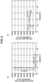
- this operation for example, within the range of the heating temperature of the hot-dip zinc plated steel sheet S as illustrated in FIG. 2 , it is possible to create a model indicating the relationship between the emissivity and the specular reflectance of the surface of the hot-dip zinc plated steel sheet S and the relationship between the emissivity and the diffuse reflectance of the surface of the steel sheet S.
- FIGS. 2(a) and 2(b) respectively illustrate an example of a relational model of the emissivity and the specular reflectance (specular reflection luminance value) and an example of a relational model of the emissivity and the diffuse reflectance (diffuse reflection luminance value), which are obtained by the above modeling procedure.
- the surface state of the hot-dip zinc plated steel sheet is constituted by two processes of step S1 in which the specularity gradually decreases and the diffusibility increases to almost the perfect diffusion surface, and step S2 in which the diffuse reflectance gradually decreases from the state of the perfect diffusion surface.
- the emissivity of the hot-dip zinc plated steel sheet can be accurately estimated by measuring the specular reflectance and the diffuse reflectance of the surface of the hot-dip zinc plated steel sheet. This makes it possible to perform accurate calculation of the surface temperature of the hot-dip zinc plated steel sheet by using the radiation light amount and the emissivity regardless of the fluctuation in the emissivity of the surface of the hot-dip zinc plated steel sheet during the production of the hot-dip zinc plated steel sheet. In addition, by manufacturing a hot-dip zinc plated steel sheet based on the calculated surface temperature, the hot-dip zinc plated steel sheet can be manufactured with good yield.
- the specular reflectance and the diffuse reflectance of the hot-dip zinc plated steel sheet can be obtained by measuring relative values with respect to the specular reflectance and the diffuse reflectance of a sample piece having a reflectance as a normal reference being close to 1.
- the sample piece can be a gold mirror and an aluminum mirror for acquisition of the specular reflectance, and can be barium sulfate for acquisition of the diffuse reflectance.
- the modeling can be performed using a reflection light amount with reference to the light amount of the light source. In this case, a light source with a constant irradiation light amount can be applied to an imaging system with a constant sensitivity, and the obtained luminance value can be directly used as a model.
- the shutter is used in the modeling procedure described above, it is not always necessary to use the shutter as long as it is possible to acquire the specular reflection image, the diffuse reflection image, and the self-emitted light image in the same surface state.
- it is allowable to prepare a plurality of samples in states of different degrees of alloying, measure the specular reflectance and the diffuse reflectance, and further heat the sample to such an extent that the surface state does not change to obtain the emissivity to achieve modeling.
- the radiation light amount, the amount of specular reflection light, and the diffuse reflection light amount are acquired from the hot-dip zinc plated steel sheet of the actual line.
- the emissivity is calculated using the model from the acquired specular reflection light amount and diffuse reflection light amount.
- the specular reflection light amount obtained by actual measurement is Rs and the diffuse reflection light amount is Rd
- the coordinate position (degree of alloying) and the emissivity on the model at the time of measurement can be estimated by distance minimization as in the following Formula (1).
- weights may be applied to the specular reflection light amount and the diffuse reflection light amount as necessary. Naturally, a similar result can be obtained even when the norm of the distance is changed.
- step S1 and step S2 can be separated as clearly different physical phenomena. Accordingly, it is allowable to first select whether the surface state of the hot-dip zinc plated steel sheet is classified into step S1 or step S2, and then calculate the coordinate position on the model in each process. For example, a simplest method would be setting a threshold for the specular reflectance, and classifying the state to step S1 when the specular reflectance is the threshold or more, and classifying the state into step S2 when the specular reflectance is less than the threshold.
- step S1 since the emissivity hardly fluctuates, the emissivity can be set to a fixed value (about 0.2), and in step S2, the coordinate position on the model and the emissivity can be estimated from the value of the diffuse reflection light amount.
- a fixed value about 0.2
- step S2 the coordinate position on the model and the emissivity can be estimated from the value of the diffuse reflection light amount.
- FIG. 3 illustrates a comparison represented by the result (present invention example) obtained, actually in a laboratory, by calculating the emissivity from the specular reflectance and the diffuse reflectance, correcting the calculated emissivity, and then measuring the temperature and the result (monochromatic radiation thermometer) obtained by fixing the emissivity to 0.2 and measuring the temperature, with respect to the temperature measured by the thermocouple 1.
- a vertical axis represents a radiation temperature measurement result
- a horizontal axis represents a temperature measurement result with a thermocouple as a true value. In this measurement, the hot-dip zinc plated steel sheet was gradually heated, and the temperature was measured during the progress of alloying.
- the actual emissivity is about 0.2 in the region near the start of heating in which alloying is not progressed in the hot-dip zinc plated steel sheet. Therefore, even in the monochromatic radiation thermometer in which the emissivity is fixed to 0.2, and also in the present invention example in which each reflectance is measured and the emissivity is estimated to be about 0.2, both results match the temperature measurement result of the thermocouple. Thereafter, alloying proceeded with heating with a gradual increase in the actual emissivity, the measured temperature value of the monochromatic radiation thermometer assuming an emissivity of 0.2 deviated upward as compared with the value of the thermocouple, leading to a final error of about 60°C as illustrated in FIG. 3 .
- the present invention example estimates the emissivity from each reflectance, it is possible to cope with an actual change in emissivity at the time of temperature measurement. Accordingly, with respect to the fluctuation in the emissivity of the surface generated in step S1 and step S2, the temperature measurement result of the present invention example substantially matches the temperature measurement result of the thermocouple.
- the degree of progress of alloying fluctuates depending on various operating conditions, not necessarily correlating with the temperature. Therefore, it is necessary, in the temperature measurement target region, to correctly measure the temperature regardless of the progress degree of alloying.
- the error increases in the monochromatic radiation thermometer assuming a specific emissivity.
- the present invention example can accurately estimate the emissivity regardless of the degree of progress of alloying, making it possible to constantly measure the temperature with high accuracy.
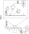
- FIG. 4 illustrates an application example of the temperature measuring apparatus according to an embodiment of the present invention to an actual line.
- a temperature measuring apparatus 10 according to an embodiment of the present invention was installed immediately after molten zinc was attached to a steel sheet in a molten zinc pot 11 and then heated to an alloying target temperature in a heating furnace 12 (on the entrance side of a heat retention zone 13).
- the temperature measuring apparatus 10 includes the radiation thermometer 4, the specular reflection light source 5, and the diffuse reflection light source 6 illustrated in FIG. 1 .
- the surface temperature of the hot-dip zinc plated steel sheet S is about 450°C to 550°C, radiation light has a great intensity, making it necessary to have the specular reflection light source 5 and the diffuse reflection light source 6 with very high intensity.
- the light amount is smaller in the diffuse reflection light amount compared with the specular reflection light, it is most preferable to use a halogen lamp.
- the halogen lamp requires several minutes or more to be started up for stabilization of the light amount after turn-on, it is preferable to switch turn-on/off using the shutter 7 for enabling constant lighting.
- an infrared LED may be used with sufficient attention to the issue of the light amount
- an infrared laser may be used with sufficient attention to the reflection polarization characteristic of the object.
- the specular reflection light source 5 is installed in the downstream of the diffuse reflection light source 6 in the conveyance direction of the hot-dip zinc plated steel sheet S.
- the installation positions of the specular reflection light source 5 and the diffuse reflection light source 6 may be reversed.
- the specular reflection light source 5 and diffuse reflection light source 6 may be installed at the same position on the passline of hot-dip zinc plated steel sheet S.
- environmental factors such as fluctuation of the passline, ease of deposition of dust, and heat influence.
- a longitudinal direction of the hot-dip zinc plated steel sheet S is defined as a y-axis direction
- a width direction of the hot-dip zinc plated steel sheet S is defined as a c-axis direction
- the amount of fluctuation of the passline position of the hot-dip zinc plated steel sheet S from a reference position is defined as ⁇ d
- the amount of angular fluctuation of the surface of the hot-dip zinc plated steel sheet S from a reference angle in an x-axis direction is defined as ⁇ x
- the amount of angular fluctuation from a reference angle in the y-axis direction is defined as ⁇ y.
- the position of the specular reflection light source 5 in the specular reflection direction with respect to an imaging visual field of the radiation thermometer 4 fluctuates by ⁇ L1 ⁇ y/cos ⁇ .
- the position of the specular reflection light source 5 in the specular reflection direction with respect to the visual field of the radiation thermometer 4 fluctuates by ⁇ L1 ⁇ x/cos ⁇ 1.
- the size of the light emitting surface of the specular reflection light source 5 is larger including the fluctuation ⁇ L1 ⁇ x/cos ⁇ 1 in the x-axis direction and the fluctuation ⁇ (2 ⁇ d ⁇ sin ⁇ 1 + L1 ⁇ y/cos ⁇ ) in the y-axis direction.
- the difference in irradiation position due to the fluctuation amount of the passline in the y-axis direction on the surface of the hot-dip zinc plated steel sheet S is ⁇ ⁇ d ⁇ sin ⁇ 2
- the difference in imaging position is ⁇ ⁇ d ⁇ sin ⁇ 1
- the displacement direction of the irradiation position and the imaging position is opposite due to an arrangement relationship.
- the displacement direction of the irradiation position and the imaging position is opposite due to an arrangement relationship.
- the diffuse reflection light source 6 is preferably installed at a position with the distance L2 capable of uniform irradiation within a range of ⁇ d(sin ⁇ 2-sin ⁇ 1) in the y-axis direction.
- the installation condition is more preferably set to have a further margin in consideration of other conditions such as installation accuracy.
- the diffuse reflection light source needs to be applied to an optical system under a condition of a low reflectance such as a diffuse reflection condition, and at the same time, needs to ensure a sufficiently high reflection light amount with respect to self-emitted light, which requires irradiation of light with very high intensity.
- a condition of a low reflectance such as a diffuse reflection condition
- using an excessively high-intensity infrared light source, for example, a halogen light source would allow the light source itself to heat the hot-dip zinc plated steel sheet, leading to a possibility of a change in the surface temperature of the hot-dip zinc plated steel sheet. Therefore, based on the concept of radiation heat transfer, the condition illustrated in the following formula (2) is to be preferably satisfied.
- an allowable temperature change amount is ⁇ T(°C)
- an output of the diffuse reflection light source is P(W)
- an absorptivity (emissivity) of the hot-dip zinc plated steel sheet in an irradiation region of the diffuse reflection light source is ⁇ h
- an irradiation area of the diffuse reflection light source on the hot-dip zinc plated steel sheet is ⁇ (mm 2 )
- a thickness of the hot-dip zinc plated steel sheet is t(mm)
- a specific gravity of iron is ⁇ (g/mm 3 )
- a specific heat of iron is c (J/g)
- an irradiation region of the diffuse reflection light source in the longitudinal direction of the hot-dip zinc plated steel sheet is l(m)
- the conveyance line speed of the hot-dip zinc plated steel sheet is v(m/s).
- the output P(W) of the halogen light source is 100(W)
- the absorptivity (emissivity) ⁇ h of the hot-dip zinc plated steel sheet in the irradiation region of the halogen light source is 0.8
- the irradiation area ⁇ (mm 2 ) of the halogen light source on the hot-dip zinc plated steel sheet is 10000 (mm 2 )
- the thickness t(mm) of the hot-dip zinc plated steel sheet is 1(mm)
- the specific gravity ⁇ (g/mm 3 ) of iron is 0.78 (g/mm 3 )
- the specific heat c(J/g) of iron is 0.435 (J/g)
- the irradiation region l(m) of the halogen light source in the longitudinal direction of the hot-dip zinc plated steel sheet is 100(m)
- the conveyance line speed v(m/s) of the hot-dip zinc plated steel sheet is
- the present embodiment performs imaging on the moving hot-dip zinc plated steel sheet by switching the radiation light amount, the specular reflection light amount, and the diffuse reflection light amount, at mutually different timings.
- the imaging be completed three times in total, that is, once for measuring the radiation light amount, once for measuring the specular reflection light amount, and once for measuring the diffuse reflection light amount, within a range that can be regarded as the same surface property. That is, the present embodiment assumes that alloying progress is the same when estimating the emissivity from the specular reflection luminance and the diffuse reflection luminance, and therefore, when the specular reflection light amount measurement and the diffuse reflection light amount measurement are performed with different surface properties, it would be difficult to estimate the emissivity by the model.
- the actual emissivity and the estimated emissivity would be different.
- the distribution of the degree of alloying unevenness of the hot-dip zinc plated steel sheet changes in a narrow range, and the surface properties of the portions are not the same due to the relationship among the responsiveness of the mechanical shutter, the exposure time, and the conveyance speed of the hot-dip zinc plated steel sheet, it is preferable to perform correction using filtering in the spatial direction or the temporal direction.
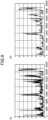
- FIGS. 9(a) and 9(b) illustrate actual temperature measurement results before and after filtering, respectively.
- the filtering was performed for 30 seconds, and the median of the radiation light amount, the specular reflection light amount, and the diffuse reflection light amount were used.
- the surface temperature can be measured with less delay by using a configuration of the temperature measuring apparatus of modifications described below.
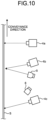
- FIG. 10 illustrates a configuration of a first modification of the temperature measuring apparatus according to an embodiment of the present invention.
- three radiation thermometers are installed in series with respect to the conveyance direction of the hot-dip zinc plated steel sheet S and at the same position in the width direction of the hot-dip zinc plated steel sheet S.
- the three radiation thermometers are: a radiation thermometer 4a not including a light source; a radiation thermometer 4b including the specular reflection light source 5; and a radiation thermometer 4c including the diffuse reflection light source 6.
- the three radiation thermometers may be installed in any order, it is preferable to install the three radiation thermometers so as not to allow the irradiation light beams of the light sources to interfere with each other.
- Such a configuration enables alignment of imaging data of each radiation thermometer based on the conveyance speed of the hot-dip zinc plated steel sheet S and the distance between the radiation thermometers, making it possible to use a high-intensity halogen light source at a high imaging cycle without switching the light source by a mechanical shutter.
- the same portion on the surface of the steel sheet can be imaged with the imaging cycle of the radiation thermometer.
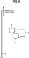
- FIG. 11 illustrates a second modification of the temperature measuring apparatus according to an embodiment of the present invention.
- the radiation thermometer 4 is constituted with a line sensor or an area sensor having a long visual field in the conveyance direction of the hot-dip zinc plated steel sheet S.
- the visual field in the longitudinal direction of the radiation thermometer 4 is divided into three, light shielding plates 9a and 9b are installed, and then, each visual field is imaged as a radiation light region, a specular reflection light irradiation region, and a diffuse reflection light irradiation region.
- a high-intensity halogen light source can be used at a high imaging cycle without switching the light source by a mechanical shutter.
- the apparatus in consideration of a difference in spectral sensitivity characteristic between the end and a central portion of the imaging visual field. Specifically, regarding visual field under the diffuse reflection condition that greatly influences the emissivity and the visual field for measuring the radiation light amount, it is preferable to set the position at the same distance from the center of the visual field.
- the incident angle of light to the radiation thermometer at the end of the imaging visual field is different from the incident angle at the center of the imaging visual field.
- the diffuse reflection light amount influences the accuracy more than the specular reflection light amount, it is preferable to arrange the light source and the sensor such that the incident positions of the radiation light and the diffuse reflection component are at the same distance from the center position in the imaging visual field.
- a hot-dip zinc plated steel sheet is set as a measurement object.
- the measurement object is not limited to the hot-dip zinc plated steel sheet, and the present invention can be generally applied to substances in which the emissivity can be uniquely determined from specular reflection light and diffuse reflection light.
- other embodiments, examples, operation techniques, and the like made by those skilled in the art based on the present embodiment are all included in the scope of the present invention as defined by the appended claims.
- the present invention may be applied to a temperature measurement step included in a method of manufacturing a hot-dip zinc plated steel sheet, and the temperature of the hot-dip zinc plated steel sheet may be measured in a known or existing step of manufacturing a hot-dip zinc plated steel sheet.
- the method of manufacturing a hot-dip zinc plated steel sheet includes: a temperature measurement step of measuring a surface temperature of a hot-dip zinc plated steel sheet by the hot-dip zinc plated steel sheet temperature measuring method according to the present invention; and a step of controlling manufacturing conditions of the hot-dip zinc plated steel sheet based on the measured surface temperature of the hot-dip zinc plated steel sheet.
- the temperature measurement step uses the temperature measured in the temperature measurement step to control a condition of one or a plurality of processes before the temperature measurement step among the processes included in the manufacturing step.
- the control is used in the case of measuring the temperature of the steel sheet to which zinc is attached or not attached during conveyance, it is most favorable because the effect of the present invention can be utilized to the maximum.
- the step may be provided immediately after the heating apparatus that promotes alloying, which is after zinc adhesion to the surface of the steel sheet, and feedback control may be used for the output of the heating apparatus so as to obtain a temperature on the heating apparatus exit side with an appropriate degree of alloying. Furthermore, control may be performed to obtain an appropriate degree of alloying by performing a feedback of output to an actuator that controls a factor having an influence on the likelihood of alloying, such as a dew point in the preceding process. In particular, it is most preferable to provide the step in the middle of a hot-dip galvanizing line for applying hot-dip zinc plating to a steel sheet.
- an induction heating furnace also referred to as an IH heating furnace as abbreviation
- the maximum temperature in the alloying process is too low, the alloying does not sufficiently progress, and when the maximum temperature is too high, the crystal grains of the structure become coarse and adversely affect the material, having a possibility of excessive progress of alloying. Therefore, temperature control is very important.
- By controlling the output of the IH heating furnace so that the temperature immediately after the IH exit side is within a predetermined control range using the present apparatus it is possible to manufacture a hot-dip zinc plated steel sheet having a target material and a target degree of alloying.
- the present invention is most effective for the production of the hot-dip galvannealed steel sheet (GA) among hot-dip zinc plated steel sheets.
- the present invention may be applied as a temperature measuring apparatus constituting a manufacturing equipment for a hot-dip zinc plated steel sheet.
- a hot-dip zinc plated steel sheet may be manufactured using the manufacturing equipment on the basis of the surface temperature of the hot-dip zinc plated steel sheet measured by the temperature measuring apparatus according to the present invention.
- the manufacturing equipment for manufacturing the hot-dip zinc plated steel sheet may be any of known, unknown, and existing facilities.
- the manufacturing equipment for manufacturing the hot-dip zinc plated steel sheet includes a hot-dip zinc plating equipment for applying hot-dip zinc plating to the steel sheet.
- the temperature measuring apparatus according to the present invention is preferably provided in the conveyance equipment. Furthermore, it is most preferable that the transfer roller is provided between two conveyance rollers provided in the hot-dip zinc plating equipment.
- the present invention is most effective in manufacturing the hot-dip galvannealed steel sheet (GA) among hot-dip zinc plated steel sheets.
- the present invention may be applied to a steel sheet quality control method, and the quality control of the steel sheet may be performed by measuring the temperature of the steel sheet.
- the temperature of the steel sheet is measured in the temperature measurement step, and the quality control of the steel sheet can be performed based on the measurement result obtained in the temperature measurement step.
- a subsequent quality control step determines whether the manufactured steel sheet satisfies a predetermined standard based on the measurement result obtained in the temperature measurement step to achieve quality control of the steel material.
- a high-quality steel sheet can be provided.
- the present invention is most effective in manufacturing the hot-dip galvannealed steel sheet (GA) among hot-dip zinc plated steel sheets.
- the surface temperature of the actual CGL induction-heating furnace exit side hot-dip zinc plated steel sheet was measured by the configuration illustrated in FIG. 4 using the model illustrated in FIG. 2 . It is known that the surface emissivity greatly fluctuates on the exit side of the IH heating furnace due to alloying of the zinc plate and the steel sheet.
- the radiation thermometer uses an area sensor of an InGaAs element with an optical system that transmits only a wavelength of 1550 ⁇ 50 nm by a long pass filter.
- An infrared LED was used as a specular reflection light source, and a halogen light source and a mechanical shutter were used as a diffuse reflection light source.
- the exposure time was set to 150 ⁇ s for the radiation light amount, 200 ⁇ s for the specular reflection light amount and the diffuse reflection light amount.
- the specular reflection light amount and the diffuse reflection light amount were each corrected by subtracting the radiation light component.
- the median filtering was performed for 30 seconds for each light amount obtained.
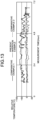
- FIG. 12 illustrates transitions of the obtained radiation light amount, the corrected specular reflection light amount, and the corrected diffuse reflection light amount.
- the horizontal axis represents the measurement time (unit: hour), and the vertical axis represents the luminance value.
- a threshold is set for the specular reflectance using the measurement result of FIG. 12 .
- step S1 When the specular reflectance is the threshold or more, step S1 is performed; when the specular reflectance is less than the threshold, step S2 is performed.
- the coordinate position and the emissivity on the model are estimated using the fixed emissivity (about 0.2) in step S1 and using the value of the diffuse reflection component in step S2.
- FIG. 13 illustrates temperature measurement results for the same measurement region of a hot-dip zinc plated steel sheet.
- the figure includes present invention example, Comparative Example 1 (monochromatic radiation temperature measurement) in which the surface temperature is calculated with the emissivity as a fixed value, and Comparative Example 2 (simulation) in which the surface temperature is calculated using heat transfer calculation.
- the horizontal axis represents the measurement time (unit: hour)
- the vertical axis represents the relative temperature (unit: °C).
- the relative temperature indicates the temperature change (°C) from a certain reference temperature defined as 0°C.
- FIG. 14 illustrates the degree of alloying at a portion where the surface temperature of the present invention example is different from the surface temperature of Comparative Example 2.
- the vertical axis represents the relative measured temperature (unit: °C)
- the horizontal axis represents the degree of alloying (unit: mass%).
- the relative measured temperature indicates the temperature change (°C) from a certain reference temperature defined as 0°C.
- the relative degree of alloying indicates the change of mass% from a certain reference alloying degree defined as 0 mass%.
- the degree of alloying indicates the Fe concentration in a case where the entire alloying phase is 100 mass% in a hot-dip zinc plated steel sheet in terms of mass percentage (mass%), and too high or too low concentration will result in poor quality.
- Measurement of the degree of alloying can be performed by using a method of calculating the degree of alloying from the mass of iron generally chemically separated and contained, or a method using X-ray diffraction (XRD).
- the surface temperature measuring method and the surface temperature measuring apparatus capable of accurately measuring the surface temperature of a measurement object regardless of fluctuations in the emissivity of the surface of the measurement object.
Landscapes
- Chemical & Material Sciences (AREA)
- Engineering & Computer Science (AREA)
- Organic Chemistry (AREA)
- Materials Engineering (AREA)
- Mechanical Engineering (AREA)
- Metallurgy (AREA)
- Chemical Kinetics & Catalysis (AREA)
- Physics & Mathematics (AREA)
- General Physics & Mathematics (AREA)
- Spectroscopy & Molecular Physics (AREA)
- Quality & Reliability (AREA)
- Coating With Molten Metal (AREA)
- Radiation Pyrometers (AREA)
Claims (8)
- Procédé de mesure de température de surface comprenant :une première étape d'imagerie consistant à acquérir une quantité de lumière de rayonnement d'une surface d'un objet de mesure ;une deuxième étape d'imagerie consistant à irradier la surface de l'objet de mesure avec de la lumière en condition de réflexion spéculaire et à acquérir une quantité de lumière de réflexion spéculaire ;une troisième étape d'imagerie consistant à irradier la surface de l'objet de mesure avec de la lumière en condition de réflexion diffuse et à acquérir une quantité de lumière de réflexion diffuse ;dans le cas où une quantité de lumière de réflexion spéculaire acquise lors de la deuxième étape d'imagerie est inférieure à une valeur prédéterminée, une étape de calcul d'émissivité consistant à calculer une émissivité de la surface de l'objet de mesure en utilisant un modèle indiquant une relation entre une émissivité et une réflectance spéculaire, et une relation entre l'émissivité et une réflectance diffuse de la surface de l'objet de mesure, la quantité de lumière de réflexion spéculaire acquise lors de la deuxième étape d'imagerie et la quantité de lumière de réflexion diffuse acquise lors de la troisième étape d'imagerie, dans le cas où la lumière de réflexion spéculaire acquise lors de la deuxième étape d'imagerie est supérieure ou égale à une valeur prédéterminée, une valeur fixe est utilisée comme étant l'émissivité ; etune étape de mesure de température consistant à calculer une température de surface de l'objet de mesure en utilisant la quantité de lumière de rayonnement acquise lors de la première étape d'imagerie et l'émissivité calculée lors de l'étape de calcul d'émissivité ou déterminée par la valeur fixe.
- Procédé de mesure de température de surface selon la revendication 1, dans lequel chacune de la deuxième étape d'imagerie et de la troisième étape d'imagerie comprend une étape de correction de la quantité de lumière de réflexion spéculaire et de la quantité de lumière de réflexion diffuse par soustraction de la quantité de lumière de rayonnement acquise lors de la première étape d'imagerie.
- Procédé de mesure de température de surface selon la revendication 1 ou 2, dans lequel la première étape d'imagerie, la deuxième étape d'imagerie et la troisième étape d'imagerie comprennent une étape de réception de la lumière en utilisant un élément de réception de lumière ayant une pluralité de champs visuels auxquels sont attribuées des plages d'acquisition de la quantité de lumière de rayonnement, de la quantité de lumière de réflexion spéculaire et de la quantité de lumière de réflexion diffuse dans une direction de transport de l'objet de mesure.
- Procédé de mesure de température de surface selon l'une quelconque des revendications 1 à 3, dans lequel l'objet de mesure est une tôle d'acier zinguée à chaud (S).
- Appareil de mesure de température de surface (10) comprenant :une première unité d'imagerie (4) configurée pour acquérir une quantité de lumière de rayonnement d'une surface d'un objet de mesure ;une deuxième unité d'imagerie (4, 5) configurée pour irradier la surface de l'objet de mesure avec de la lumière en condition de réflexion spéculaire et pour acquérir une quantité de lumière de réflexion spéculaire ;une troisième unité d'imagerie (4, 6) configurée pour irradier la surface de l'objet de mesure avec de la lumière en condition de réflexion diffuse et pour acquérir une quantité de lumière de réflexion diffuse ;une unité de calcul d'émissivité (8) configurée pour calculer, dans le cas où une quantité de lumière de réflexion spéculaire acquise par la deuxième unité d'imagerie est inférieure à une valeur prédéterminée, une émissivité de la surface de l'objet de mesure en utilisant un modèle indiquant une relation entre une émissivité et une réflectance spéculaire, et une relation entre l'émissivité et une réflectance diffuse de la surface de l'objet de mesure, la quantité de lumière de réflexion spéculaire acquise par la deuxième unité d'imagerie et la quantité de lumière de réflexion diffuse acquise par la troisième unité d'imagerie, et dans le cas où la lumière de réflexion spéculaire acquise par la deuxième unité d'imagerie est supérieure ou égale à une valeur prédéterminée, utiliser une valeur fixe comme étant l'émissivité ; etune unité de mesure de température (8) configurée pour calculer une température de surface de l'objet de mesure en utilisant la quantité de lumière de rayonnement acquise par la première unité d'imagerie et l'émissivité calculée par l'unité de calcul d'émissivité ou déterminée par la valeur fixe.
- Appareil de mesure de température de surface (10) selon la revendication 5, dans lequel l'objet de mesure est une tôle d'acier zinguée à chaud (S).
- Procédé de fabrication d'une tôle d'acier zinguée à chaud (S) comprenant des étapes de fabrication consistant à fabriquer une tôle d'acier zinguée à chaud (S), les étapes de fabrication consistant à fabriquer la tôle d'acier zinguée à chaud (S) comprenant : une étape de mesure de température consistant à mesurer une température de surface de la tôle d'acier zinguée à chaud (S) par le procédé de mesure de température de surface selon l'une quelconque des revendications 1 à 4 ; et une étape de commande des conditions de fabrication lors des étapes de fabrication en utilisant la température de surface mesurée lors de l'étape de mesure de température.
- Équipement de fabrication d'une tôle d'acier zinguée à chaud (S) comprenant :l'appareil de mesure de température de surface (10) selon la revendication 5 ou 6 ; etun équipement qui fabrique une tôle d'acier zinguée à chaud (S) sur la base d'une température de surface d'une tôle d'acier zinguée à chaud (S) mesurée par l'appareil de mesure de température de surface (10).
Applications Claiming Priority (2)
| Application Number | Priority Date | Filing Date | Title |
|---|---|---|---|
| JP2020179302 | 2020-10-27 | ||
| PCT/JP2021/031087 WO2022091541A1 (fr) | 2020-10-27 | 2021-08-25 | Procédé de mesure de température de surface, dispositif de mesure de température de surface, procédé de fabrication de tôle d'acier galvanisée à chaud, et installation de fabrication de tôle d'acier galvanisée à chaud |
Publications (3)
| Publication Number | Publication Date |
|---|---|
| EP4212837A1 EP4212837A1 (fr) | 2023-07-19 |
| EP4212837A4 EP4212837A4 (fr) | 2024-03-27 |
| EP4212837B1 true EP4212837B1 (fr) | 2025-06-04 |
Family
ID=81382247
Family Applications (1)
| Application Number | Title | Priority Date | Filing Date |
|---|---|---|---|
| EP21885660.7A Active EP4212837B1 (fr) | 2020-10-27 | 2021-08-25 | Procédé de mesure de température de surface, dispositif de mesure de température de surface, procédé de fabrication de tôle d'acier galvanisée à chaud, et installation de fabrication de tôle d'acier galvanisée à chaud |
Country Status (7)
| Country | Link |
|---|---|
| US (1) | US20230366073A1 (fr) |
| EP (1) | EP4212837B1 (fr) |
| JP (1) | JP7276515B2 (fr) |
| KR (1) | KR102818192B1 (fr) |
| CN (1) | CN116472440B (fr) |
| MX (1) | MX2023004382A (fr) |
| WO (1) | WO2022091541A1 (fr) |
Families Citing this family (2)
| Publication number | Priority date | Publication date | Assignee | Title |
|---|---|---|---|---|
| JP7518456B2 (ja) * | 2022-08-05 | 2024-07-18 | 日本製鉄株式会社 | 温度測定装置及び温度測定方法 |
| JP7852583B2 (ja) * | 2023-06-29 | 2026-04-28 | Jfeスチール株式会社 | 帯状物体表面の物理量計測方法、帯状物体表面の物理量計測装置、帯状物体の形状制御方法、鋼板の製造方法、及び鋼板の製造設備 |
Family Cites Families (28)
| Publication number | Priority date | Publication date | Assignee | Title |
|---|---|---|---|---|
| US4465382A (en) * | 1980-03-04 | 1984-08-14 | Nippon Steel Corporation | Method of and an apparatus for measuring surface temperature and emmissivity of a heated material |
| JPH0663848B2 (ja) * | 1986-06-27 | 1994-08-22 | 新日本製鐵株式会社 | 物体の表面温度測定方法 |
| JPH01245125A (ja) * | 1988-03-28 | 1989-09-29 | Sumitomo Metal Ind Ltd | 放射率と温度の同時測定方法及びその装置 |
| JPH0458568A (ja) | 1990-06-28 | 1992-02-25 | Mitsubishi Materials Corp | アルファ線検出装置 |
| JPH05209792A (ja) | 1992-01-31 | 1993-08-20 | Sumitomo Metal Ind Ltd | 放射率と表面温度の同時測定方法および該方法に使用する装置 |
| JPH05231945A (ja) * | 1992-02-26 | 1993-09-07 | Sumitomo Metal Ind Ltd | 溶融亜鉛メッキ鋼板の表面温度および放射率の測定方法 |
| JP2737554B2 (ja) * | 1992-07-06 | 1998-04-08 | 住友金属工業株式会社 | 放射率と表面温度の測定方法及びその装置 |
| JP3291781B2 (ja) * | 1992-08-27 | 2002-06-10 | 日本鋼管株式会社 | 鋼板の温度測定方法及び装置 |
| JPH0763613A (ja) * | 1993-08-24 | 1995-03-10 | Kobe Steel Ltd | 放射温度計 |
| IL110549A (en) * | 1994-08-02 | 1998-02-08 | C I Systems Israel Ltd | Multipoint temperature monitoring apparatus for semiconductor wafers during processing |
| JP3296171B2 (ja) * | 1995-12-18 | 2002-06-24 | 日本鋼管株式会社 | 物体の温度測定方法及び装置 |
| JP3296224B2 (ja) | 1996-12-26 | 2002-06-24 | 日本鋼管株式会社 | 物体の放射率測定方法及び温度測定装置 |
| US6342885B1 (en) * | 1998-11-12 | 2002-01-29 | Tera Recon Inc. | Method and apparatus for illuminating volume data in a rendering pipeline |
| AU2003225518A1 (en) * | 2002-04-10 | 2003-10-27 | D.G.Y. Infrared Ltd. | Apparatus and method for true temperature estimation |
| JP2004301604A (ja) * | 2003-03-31 | 2004-10-28 | Chino Corp | 放射温度測定装置及び光学的測定装置 |
| JP2005209792A (ja) | 2004-01-21 | 2005-08-04 | Matsushita Electric Ind Co Ltd | 半導体装置 |
| JP2005233790A (ja) * | 2004-02-19 | 2005-09-02 | Nippon Steel Corp | 鋼板の温度測定方法および装置 |
| JP5335462B2 (ja) | 2009-02-10 | 2013-11-06 | 本田技研工業株式会社 | 車両用メータ装置 |
| US8568021B2 (en) * | 2011-09-29 | 2013-10-29 | Schwank Ltd. | Apparatus and method for measuring heat flux from radiant heater |
| JP6035831B2 (ja) * | 2012-04-13 | 2016-11-30 | Jfeスチール株式会社 | 温度測定方法および温度測定装置 |
| WO2016158873A1 (fr) * | 2015-03-31 | 2016-10-06 | 日新製鋼株式会社 | Dispositif d'inspection des défauts superficiels dans une tôle d'acier galvanisée à chaud, et procédé associé |
| JP6447637B2 (ja) * | 2015-06-25 | 2019-01-09 | Jfeスチール株式会社 | 表面欠陥検出装置、表面欠陥検出方法、及び鋼材の製造方法 |
| JP6117398B1 (ja) * | 2016-03-30 | 2017-04-19 | 日新製鋼株式会社 | 鋼板の表面欠陥検査装置および表面欠陥検査方法 |
| GB2569644B (en) * | 2017-12-22 | 2020-08-19 | Land Instruments International Ltd | Measurement system for metal strip production line |
| US11073423B2 (en) * | 2018-03-27 | 2021-07-27 | Flying Gybe Inc. | Hyperspectral sensing system and processing methods for hyperspectral data |
| JP7062339B2 (ja) * | 2018-08-30 | 2022-05-06 | 株式会社チノー | 温度測定方法及び温度測定装置 |
| CN110132421B (zh) * | 2019-04-12 | 2021-06-11 | 东北大学 | 一种快速精确连续测量液体介质内部温度的装置及方法 |
| JP2025036884A (ja) * | 2023-09-05 | 2025-03-17 | Jfeスチール株式会社 | 物理量計測方法および物理量計測システム |
-
2021
- 2021-08-25 EP EP21885660.7A patent/EP4212837B1/fr active Active
- 2021-08-25 KR KR1020237014053A patent/KR102818192B1/ko active Active
- 2021-08-25 WO PCT/JP2021/031087 patent/WO2022091541A1/fr not_active Ceased
- 2021-08-25 US US18/031,119 patent/US20230366073A1/en active Pending
- 2021-08-25 JP JP2021570285A patent/JP7276515B2/ja active Active
- 2021-08-25 CN CN202180072737.2A patent/CN116472440B/zh active Active
- 2021-08-25 MX MX2023004382A patent/MX2023004382A/es unknown
Also Published As
| Publication number | Publication date |
|---|---|
| MX2023004382A (es) | 2023-05-04 |
| KR102818192B1 (ko) | 2025-06-10 |
| WO2022091541A1 (fr) | 2022-05-05 |
| EP4212837A1 (fr) | 2023-07-19 |
| EP4212837A4 (fr) | 2024-03-27 |
| KR20230073318A (ko) | 2023-05-25 |
| JP7276515B2 (ja) | 2023-05-18 |
| US20230366073A1 (en) | 2023-11-16 |
| CN116472440B (zh) | 2026-03-20 |
| JPWO2022091541A1 (fr) | 2022-05-05 |
| CN116472440A (zh) | 2023-07-21 |
Similar Documents
| Publication | Publication Date | Title |
|---|---|---|
| EP4212837B1 (fr) | Procédé de mesure de température de surface, dispositif de mesure de température de surface, procédé de fabrication de tôle d'acier galvanisée à chaud, et installation de fabrication de tôle d'acier galvanisée à chaud | |
| US20250018424A1 (en) | Method for managing coating gloss on a coil-coating line | |
| CN110657892B (zh) | 钛合金电弧焊熔池表面温度场测量装置和方法 | |
| EP3729026B1 (fr) | Système de mesure pour ligne de production de bande métallique | |
| JP7396328B2 (ja) | 亜鉛系溶融めっき鋼板の温度測定方法、温度測定装置、及び製造方法 | |
| JPH0933455A (ja) | 合金化めっき層の合金化度測定方法 | |
| EP0531963B1 (fr) | Procédé de contrÔle de l'échauffement d'un four de recuit pour la fabrication d'une bande d'acier galvanisée et alliée | |
| JP2023120491A (ja) | 放射温度計の校正方法及び校正装置 | |
| JPH0525604A (ja) | 溶融めつき設備における合金化制御装置 | |
| JP2807156B2 (ja) | 溶融亜鉛めっき鋼板の合金化度制御方法 | |
| WO2024029231A1 (fr) | Dispositif et procédé de mesure de température | |
| JP7440517B2 (ja) | 部材の表面特性の検出方法、部材の表面品質をモニタリングするための前記方法の使用、および部材の表面特性を調整するためのデバイス | |
| JP2873125B2 (ja) | めっき付着量の測定方法および装置 | |
| JP5403041B2 (ja) | 溶融亜鉛めっき鋼板の合金化処理装置 | |
| KR100511513B1 (ko) | 지에이 강판의 철함량 편차 균일화 방법 | |
| JP7444125B2 (ja) | 金属板の表面温度測定装置、焼鈍設備及び表面温度測定方法 | |
| JPH0288954A (ja) | 亜鉛めっき鋼板の合金化度測定方法 | |
| JPH05231945A (ja) | 溶融亜鉛メッキ鋼板の表面温度および放射率の測定方法 | |
| WO2025062854A1 (fr) | Procédé de production de film, procédé de production d'objet, procédé de production de film d'oxyde et procédé de production de matériau d'acier plaqué | |
| AU685840B2 (en) | Determination of coating thickness and temperature of thinly coated substrates | |
| JP3141722B2 (ja) | 溶融亜鉛めっき鋼板の合金化度制御方法 | |
| JP2699989B2 (ja) | 溶融合金化亜鉛めっき鋼帯の合金化炉入熱制御方法 | |
| JP2024022281A (ja) | 温度測定装置及び温度測定方法 | |
| Burnett | Minimising zinc over-coating | |
| JPS61145439A (ja) | 合金化溶融亜鉛めつき鋼板の合金化度測定方法 |
Legal Events
| Date | Code | Title | Description |
|---|---|---|---|
| STAA | Information on the status of an ep patent application or granted ep patent |
Free format text: STATUS: THE INTERNATIONAL PUBLICATION HAS BEEN MADE |
|
| PUAI | Public reference made under article 153(3) epc to a published international application that has entered the european phase |
Free format text: ORIGINAL CODE: 0009012 |
|
| STAA | Information on the status of an ep patent application or granted ep patent |
Free format text: STATUS: REQUEST FOR EXAMINATION WAS MADE |
|
| 17P | Request for examination filed |
Effective date: 20230412 |
|
| AK | Designated contracting states |
Kind code of ref document: A1 Designated state(s): AL AT BE BG CH CY CZ DE DK EE ES FI FR GB GR HR HU IE IS IT LI LT LU LV MC MK MT NL NO PL PT RO RS SE SI SK SM TR |
|
| DAV | Request for validation of the european patent (deleted) | ||
| DAX | Request for extension of the european patent (deleted) | ||
| A4 | Supplementary search report drawn up and despatched |
Effective date: 20240226 |
|
| RIC1 | Information provided on ipc code assigned before grant |
Ipc: C23C 2/00 20060101ALI20240220BHEP Ipc: C23C 2/40 20060101ALI20240220BHEP Ipc: C23C 2/06 20060101ALI20240220BHEP Ipc: G01J 5/70 20220101ALI20240220BHEP Ipc: G01J 5/80 20220101ALI20240220BHEP Ipc: G01J 5/08 20220101ALI20240220BHEP Ipc: G01J 5/00 20220101AFI20240220BHEP |
|
| GRAP | Despatch of communication of intention to grant a patent |
Free format text: ORIGINAL CODE: EPIDOSNIGR1 |
|
| STAA | Information on the status of an ep patent application or granted ep patent |
Free format text: STATUS: GRANT OF PATENT IS INTENDED |
|
| INTG | Intention to grant announced |
Effective date: 20250224 |
|
| GRAS | Grant fee paid |
Free format text: ORIGINAL CODE: EPIDOSNIGR3 |
|
| GRAA | (expected) grant |
Free format text: ORIGINAL CODE: 0009210 |
|
| STAA | Information on the status of an ep patent application or granted ep patent |
Free format text: STATUS: THE PATENT HAS BEEN GRANTED |
|
| AK | Designated contracting states |
Kind code of ref document: B1 Designated state(s): AL AT BE BG CH CY CZ DE DK EE ES FI FR GB GR HR HU IE IS IT LI LT LU LV MC MK MT NL NO PL PT RO RS SE SI SK SM TR |
|
| REG | Reference to a national code |
Ref country code: GB Ref legal event code: FG4D |
|
| REG | Reference to a national code |
Ref country code: CH Ref legal event code: EP |
|
| REG | Reference to a national code |
Ref country code: DE Ref legal event code: R096 Ref document number: 602021031945 Country of ref document: DE |
|
| REG | Reference to a national code |
Ref country code: IE Ref legal event code: FG4D |
|
| REG | Reference to a national code |
Ref country code: NL Ref legal event code: MP Effective date: 20250604 |
|
| PG25 | Lapsed in a contracting state [announced via postgrant information from national office to epo] |
Ref country code: ES Free format text: LAPSE BECAUSE OF FAILURE TO SUBMIT A TRANSLATION OF THE DESCRIPTION OR TO PAY THE FEE WITHIN THE PRESCRIBED TIME-LIMIT Effective date: 20250604 Ref country code: FI Free format text: LAPSE BECAUSE OF FAILURE TO SUBMIT A TRANSLATION OF THE DESCRIPTION OR TO PAY THE FEE WITHIN THE PRESCRIBED TIME-LIMIT Effective date: 20250604 |
|
| PGFP | Annual fee paid to national office [announced via postgrant information from national office to epo] |
Ref country code: DE Payment date: 20250828 Year of fee payment: 5 |
|
| REG | Reference to a national code |
Ref country code: LT Ref legal event code: MG9D |
|
| PG25 | Lapsed in a contracting state [announced via postgrant information from national office to epo] |
Ref country code: GR Free format text: LAPSE BECAUSE OF FAILURE TO SUBMIT A TRANSLATION OF THE DESCRIPTION OR TO PAY THE FEE WITHIN THE PRESCRIBED TIME-LIMIT Effective date: 20250905 Ref country code: NO Free format text: LAPSE BECAUSE OF FAILURE TO SUBMIT A TRANSLATION OF THE DESCRIPTION OR TO PAY THE FEE WITHIN THE PRESCRIBED TIME-LIMIT Effective date: 20250904 |
|
| PG25 | Lapsed in a contracting state [announced via postgrant information from national office to epo] |
Ref country code: PL Free format text: LAPSE BECAUSE OF FAILURE TO SUBMIT A TRANSLATION OF THE DESCRIPTION OR TO PAY THE FEE WITHIN THE PRESCRIBED TIME-LIMIT Effective date: 20250604 |
|
| PGFP | Annual fee paid to national office [announced via postgrant information from national office to epo] |
Ref country code: TR Payment date: 20250821 Year of fee payment: 5 |
|
| PG25 | Lapsed in a contracting state [announced via postgrant information from national office to epo] |
Ref country code: BG Free format text: LAPSE BECAUSE OF FAILURE TO SUBMIT A TRANSLATION OF THE DESCRIPTION OR TO PAY THE FEE WITHIN THE PRESCRIBED TIME-LIMIT Effective date: 20250604 |
|
| PG25 | Lapsed in a contracting state [announced via postgrant information from national office to epo] |
Ref country code: HR Free format text: LAPSE BECAUSE OF FAILURE TO SUBMIT A TRANSLATION OF THE DESCRIPTION OR TO PAY THE FEE WITHIN THE PRESCRIBED TIME-LIMIT Effective date: 20250604 |
|
| PGFP | Annual fee paid to national office [announced via postgrant information from national office to epo] |
Ref country code: FR Payment date: 20250826 Year of fee payment: 5 Ref country code: AT Payment date: 20251020 Year of fee payment: 5 |
|
| PG25 | Lapsed in a contracting state [announced via postgrant information from national office to epo] |
Ref country code: RS Free format text: LAPSE BECAUSE OF FAILURE TO SUBMIT A TRANSLATION OF THE DESCRIPTION OR TO PAY THE FEE WITHIN THE PRESCRIBED TIME-LIMIT Effective date: 20250904 |
|
| PG25 | Lapsed in a contracting state [announced via postgrant information from national office to epo] |
Ref country code: LV Free format text: LAPSE BECAUSE OF FAILURE TO SUBMIT A TRANSLATION OF THE DESCRIPTION OR TO PAY THE FEE WITHIN THE PRESCRIBED TIME-LIMIT Effective date: 20250604 |
|
| PG25 | Lapsed in a contracting state [announced via postgrant information from national office to epo] |
Ref country code: NL Free format text: LAPSE BECAUSE OF FAILURE TO SUBMIT A TRANSLATION OF THE DESCRIPTION OR TO PAY THE FEE WITHIN THE PRESCRIBED TIME-LIMIT Effective date: 20250604 |
|
| PG25 | Lapsed in a contracting state [announced via postgrant information from national office to epo] |
Ref country code: PT Free format text: LAPSE BECAUSE OF FAILURE TO SUBMIT A TRANSLATION OF THE DESCRIPTION OR TO PAY THE FEE WITHIN THE PRESCRIBED TIME-LIMIT Effective date: 20251006 |
|
| REG | Reference to a national code |
Ref country code: AT Ref legal event code: MK05 Ref document number: 1800739 Country of ref document: AT Kind code of ref document: T Effective date: 20250604 |
|
| PG25 | Lapsed in a contracting state [announced via postgrant information from national office to epo] |
Ref country code: IS Free format text: LAPSE BECAUSE OF FAILURE TO SUBMIT A TRANSLATION OF THE DESCRIPTION OR TO PAY THE FEE WITHIN THE PRESCRIBED TIME-LIMIT Effective date: 20251004 |
|
| PG25 | Lapsed in a contracting state [announced via postgrant information from national office to epo] |
Ref country code: SM Free format text: LAPSE BECAUSE OF FAILURE TO SUBMIT A TRANSLATION OF THE DESCRIPTION OR TO PAY THE FEE WITHIN THE PRESCRIBED TIME-LIMIT Effective date: 20250604 Ref country code: AT Free format text: LAPSE BECAUSE OF FAILURE TO SUBMIT A TRANSLATION OF THE DESCRIPTION OR TO PAY THE FEE WITHIN THE PRESCRIBED TIME-LIMIT Effective date: 20250604 |
|
| PG25 | Lapsed in a contracting state [announced via postgrant information from national office to epo] |
Ref country code: CZ Free format text: LAPSE BECAUSE OF FAILURE TO SUBMIT A TRANSLATION OF THE DESCRIPTION OR TO PAY THE FEE WITHIN THE PRESCRIBED TIME-LIMIT Effective date: 20250604 |
|
| PG25 | Lapsed in a contracting state [announced via postgrant information from national office to epo] |
Ref country code: EE Free format text: LAPSE BECAUSE OF FAILURE TO SUBMIT A TRANSLATION OF THE DESCRIPTION OR TO PAY THE FEE WITHIN THE PRESCRIBED TIME-LIMIT Effective date: 20250604 |
|
| PG25 | Lapsed in a contracting state [announced via postgrant information from national office to epo] |
Ref country code: SK Free format text: LAPSE BECAUSE OF FAILURE TO SUBMIT A TRANSLATION OF THE DESCRIPTION OR TO PAY THE FEE WITHIN THE PRESCRIBED TIME-LIMIT Effective date: 20250604 |
|
| PG25 | Lapsed in a contracting state [announced via postgrant information from national office to epo] |
Ref country code: IT Free format text: LAPSE BECAUSE OF FAILURE TO SUBMIT A TRANSLATION OF THE DESCRIPTION OR TO PAY THE FEE WITHIN THE PRESCRIBED TIME-LIMIT Effective date: 20250604 |
|
| REG | Reference to a national code |
Ref country code: DE Ref legal event code: R097 Ref document number: 602021031945 Country of ref document: DE |
|
| PG25 | Lapsed in a contracting state [announced via postgrant information from national office to epo] |
Ref country code: RO Free format text: LAPSE BECAUSE OF FAILURE TO SUBMIT A TRANSLATION OF THE DESCRIPTION OR TO PAY THE FEE WITHIN THE PRESCRIBED TIME-LIMIT Effective date: 20250604 |
|
| REG | Reference to a national code |
Ref country code: CH Ref legal event code: H13 Free format text: ST27 STATUS EVENT CODE: U-0-0-H10-H13 (AS PROVIDED BY THE NATIONAL OFFICE) Effective date: 20260324 |
|
| PG25 | Lapsed in a contracting state [announced via postgrant information from national office to epo] |
Ref country code: MC Free format text: LAPSE BECAUSE OF FAILURE TO SUBMIT A TRANSLATION OF THE DESCRIPTION OR TO PAY THE FEE WITHIN THE PRESCRIBED TIME-LIMIT Effective date: 20250604 |
|
| PLBE | No opposition filed within time limit |
Free format text: ORIGINAL CODE: 0009261 |
|
| STAA | Information on the status of an ep patent application or granted ep patent |
Free format text: STATUS: NO OPPOSITION FILED WITHIN TIME LIMIT |
|
| PG25 | Lapsed in a contracting state [announced via postgrant information from national office to epo] |
Ref country code: DK Free format text: LAPSE BECAUSE OF FAILURE TO SUBMIT A TRANSLATION OF THE DESCRIPTION OR TO PAY THE FEE WITHIN THE PRESCRIBED TIME-LIMIT Effective date: 20250604 |
|
| PG25 | Lapsed in a contracting state [announced via postgrant information from national office to epo] |
Ref country code: LU Free format text: LAPSE BECAUSE OF NON-PAYMENT OF DUE FEES Effective date: 20250825 |
|
| REG | Reference to a national code |
Ref country code: CH Ref legal event code: L10 Free format text: ST27 STATUS EVENT CODE: U-0-0-L10-L00 (AS PROVIDED BY THE NATIONAL OFFICE) Effective date: 20260416 |
|
| PG25 | Lapsed in a contracting state [announced via postgrant information from national office to epo] |
Ref country code: CH Free format text: LAPSE BECAUSE OF NON-PAYMENT OF DUE FEES Effective date: 20250831 |