EP4212909A1 - Procédé de fonctionnement de transducteurs électroacoustiques, circuit et dispositif correspondants - Google Patents
Procédé de fonctionnement de transducteurs électroacoustiques, circuit et dispositif correspondants Download PDFInfo
- Publication number
- EP4212909A1 EP4212909A1 EP22213083.3A EP22213083A EP4212909A1 EP 4212909 A1 EP4212909 A1 EP 4212909A1 EP 22213083 A EP22213083 A EP 22213083A EP 4212909 A1 EP4212909 A1 EP 4212909A1
- Authority
- EP
- European Patent Office
- Prior art keywords
- transmitter
- receiver
- frequency
- signal
- transducer
- Prior art date
- Legal status (The legal status is an assumption and is not a legal conclusion. Google has not performed a legal analysis and makes no representation as to the accuracy of the status listed.)
- Granted
Links
Images








Classifications
-
- G—PHYSICS
- G01—MEASURING; TESTING
- G01S—RADIO DIRECTION-FINDING; RADIO NAVIGATION; DETERMINING DISTANCE OR VELOCITY BY USE OF RADIO WAVES; LOCATING OR PRESENCE-DETECTING BY USE OF THE REFLECTION OR RERADIATION OF RADIO WAVES; ANALOGOUS ARRANGEMENTS USING OTHER WAVES
- G01S7/00—Details of systems according to groups G01S13/00, G01S15/00, G01S17/00
- G01S7/52—Details of systems according to groups G01S13/00, G01S15/00, G01S17/00 of systems according to group G01S15/00
- G01S7/521—Constructional features
-
- G—PHYSICS
- G01—MEASURING; TESTING
- G01S—RADIO DIRECTION-FINDING; RADIO NAVIGATION; DETERMINING DISTANCE OR VELOCITY BY USE OF RADIO WAVES; LOCATING OR PRESENCE-DETECTING BY USE OF THE REFLECTION OR RERADIATION OF RADIO WAVES; ANALOGOUS ARRANGEMENTS USING OTHER WAVES
- G01S7/00—Details of systems according to groups G01S13/00, G01S15/00, G01S17/00
- G01S7/52—Details of systems according to groups G01S13/00, G01S15/00, G01S17/00 of systems according to group G01S15/00
- G01S7/523—Details of pulse systems
- G01S7/526—Receivers
-
- B—PERFORMING OPERATIONS; TRANSPORTING
- B06—GENERATING OR TRANSMITTING MECHANICAL VIBRATIONS IN GENERAL
- B06B—METHODS OR APPARATUS FOR GENERATING OR TRANSMITTING MECHANICAL VIBRATIONS OF INFRASONIC, SONIC, OR ULTRASONIC FREQUENCY, e.g. FOR PERFORMING MECHANICAL WORK IN GENERAL
- B06B1/00—Methods or apparatus for generating mechanical vibrations of infrasonic, sonic, or ultrasonic frequency
- B06B1/02—Methods or apparatus for generating mechanical vibrations of infrasonic, sonic, or ultrasonic frequency making use of electrical energy
- B06B1/06—Methods or apparatus for generating mechanical vibrations of infrasonic, sonic, or ultrasonic frequency making use of electrical energy operating with piezoelectric effect or with electrostriction
- B06B1/0644—Methods or apparatus for generating mechanical vibrations of infrasonic, sonic, or ultrasonic frequency making use of electrical energy operating with piezoelectric effect or with electrostriction using a single piezoelectric element
-
- B—PERFORMING OPERATIONS; TRANSPORTING
- B06—GENERATING OR TRANSMITTING MECHANICAL VIBRATIONS IN GENERAL
- B06B—METHODS OR APPARATUS FOR GENERATING OR TRANSMITTING MECHANICAL VIBRATIONS OF INFRASONIC, SONIC, OR ULTRASONIC FREQUENCY, e.g. FOR PERFORMING MECHANICAL WORK IN GENERAL
- B06B1/00—Methods or apparatus for generating mechanical vibrations of infrasonic, sonic, or ultrasonic frequency
- B06B1/02—Methods or apparatus for generating mechanical vibrations of infrasonic, sonic, or ultrasonic frequency making use of electrical energy
- B06B1/0207—Driving circuits
-
- G—PHYSICS
- G01—MEASURING; TESTING
- G01S—RADIO DIRECTION-FINDING; RADIO NAVIGATION; DETERMINING DISTANCE OR VELOCITY BY USE OF RADIO WAVES; LOCATING OR PRESENCE-DETECTING BY USE OF THE REFLECTION OR RERADIATION OF RADIO WAVES; ANALOGOUS ARRANGEMENTS USING OTHER WAVES
- G01S15/00—Systems using the reflection or reradiation of acoustic waves, e.g. sonar systems
- G01S15/02—Systems using the reflection or reradiation of acoustic waves, e.g. sonar systems using reflection of acoustic waves
- G01S15/06—Systems determining the position data of a target
-
- G—PHYSICS
- G01—MEASURING; TESTING
- G01S—RADIO DIRECTION-FINDING; RADIO NAVIGATION; DETERMINING DISTANCE OR VELOCITY BY USE OF RADIO WAVES; LOCATING OR PRESENCE-DETECTING BY USE OF THE REFLECTION OR RERADIATION OF RADIO WAVES; ANALOGOUS ARRANGEMENTS USING OTHER WAVES
- G01S15/00—Systems using the reflection or reradiation of acoustic waves, e.g. sonar systems
- G01S15/02—Systems using the reflection or reradiation of acoustic waves, e.g. sonar systems using reflection of acoustic waves
- G01S15/06—Systems determining the position data of a target
- G01S15/08—Systems for measuring distance only
- G01S15/10—Systems for measuring distance only using transmission of interrupted, pulse-modulated waves
- G01S15/101—Particularities of the measurement of distance
-
- G—PHYSICS
- G01—MEASURING; TESTING
- G01S—RADIO DIRECTION-FINDING; RADIO NAVIGATION; DETERMINING DISTANCE OR VELOCITY BY USE OF RADIO WAVES; LOCATING OR PRESENCE-DETECTING BY USE OF THE REFLECTION OR RERADIATION OF RADIO WAVES; ANALOGOUS ARRANGEMENTS USING OTHER WAVES
- G01S7/00—Details of systems according to groups G01S13/00, G01S15/00, G01S17/00
- G01S7/52—Details of systems according to groups G01S13/00, G01S15/00, G01S17/00 of systems according to group G01S15/00
- G01S7/523—Details of pulse systems
- G01S7/524—Transmitters
-
- G—PHYSICS
- G01—MEASURING; TESTING
- G01S—RADIO DIRECTION-FINDING; RADIO NAVIGATION; DETERMINING DISTANCE OR VELOCITY BY USE OF RADIO WAVES; LOCATING OR PRESENCE-DETECTING BY USE OF THE REFLECTION OR RERADIATION OF RADIO WAVES; ANALOGOUS ARRANGEMENTS USING OTHER WAVES
- G01S7/00—Details of systems according to groups G01S13/00, G01S15/00, G01S17/00
- G01S7/52—Details of systems according to groups G01S13/00, G01S15/00, G01S17/00 of systems according to group G01S15/00
- G01S7/523—Details of pulse systems
- G01S7/526—Receivers
- G01S7/527—Extracting wanted echo signals
- G01S7/5276—Extracting wanted echo signals using analogue techniques
-
- G—PHYSICS
- G01—MEASURING; TESTING
- G01S—RADIO DIRECTION-FINDING; RADIO NAVIGATION; DETERMINING DISTANCE OR VELOCITY BY USE OF RADIO WAVES; LOCATING OR PRESENCE-DETECTING BY USE OF THE REFLECTION OR RERADIATION OF RADIO WAVES; ANALOGOUS ARRANGEMENTS USING OTHER WAVES
- G01S7/00—Details of systems according to groups G01S13/00, G01S15/00, G01S17/00
- G01S7/52—Details of systems according to groups G01S13/00, G01S15/00, G01S17/00 of systems according to group G01S15/00
- G01S7/523—Details of pulse systems
- G01S7/526—Receivers
- G01S7/53—Means for transforming coordinates or for evaluating data, e.g. using computers
-
- H—ELECTRICITY
- H04—ELECTRIC COMMUNICATION TECHNIQUE
- H04R—LOUDSPEAKERS, MICROPHONES, GRAMOPHONE PICK-UPS OR LIKE ACOUSTIC ELECTROMECHANICAL TRANSDUCERS; ELECTRIC HEARING AIDS; PUBLIC ADDRESS SYSTEMS
- H04R17/00—Piezoelectric transducers; Electrostrictive transducers
- H04R17/10—Resonant transducers, i.e. adapted to produce maximum output at a predetermined frequency
-
- H—ELECTRICITY
- H04—ELECTRIC COMMUNICATION TECHNIQUE
- H04R—LOUDSPEAKERS, MICROPHONES, GRAMOPHONE PICK-UPS OR LIKE ACOUSTIC ELECTROMECHANICAL TRANSDUCERS; ELECTRIC HEARING AIDS; PUBLIC ADDRESS SYSTEMS
- H04R29/00—Monitoring arrangements; Testing arrangements
- H04R29/001—Monitoring arrangements; Testing arrangements for loudspeakers
-
- H—ELECTRICITY
- H04—ELECTRIC COMMUNICATION TECHNIQUE
- H04R—LOUDSPEAKERS, MICROPHONES, GRAMOPHONE PICK-UPS OR LIKE ACOUSTIC ELECTROMECHANICAL TRANSDUCERS; ELECTRIC HEARING AIDS; PUBLIC ADDRESS SYSTEMS
- H04R3/00—Circuits for transducers
- H04R3/04—Circuits for transducers for correcting frequency response
-
- H—ELECTRICITY
- H04—ELECTRIC COMMUNICATION TECHNIQUE
- H04R—LOUDSPEAKERS, MICROPHONES, GRAMOPHONE PICK-UPS OR LIKE ACOUSTIC ELECTROMECHANICAL TRANSDUCERS; ELECTRIC HEARING AIDS; PUBLIC ADDRESS SYSTEMS
- H04R2201/00—Details of transducers, loudspeakers or microphones covered by H04R1/00 but not provided for in any of its subgroups
- H04R2201/003—Mems transducers or their use
Definitions
- the description relates to techniques involving the use of electro-acoustic transducers, that is components capable of converting electrical signals into acoustic signals and/or converting acoustic signals into electrical signals.
- the description relates in particular to Piezoelectric Micromachined Ultrasonic Transducers (PMUT).
- Ultrasonic transducers can be considered for use in various applications such as acoustic location methods, wherein (ultra)sound waves can be used to determine the distance and/or the direction of a source or reflector.
- Obstacle detection (mono-, bi-, three-dimensional), volume measurement, gesture recognition and (Doppler-based) flow metering and are exemplary of possible fields of application.
- PMUTs piezoelectric Micromachined Ultrasonic Transducers
- MEMS Micro Electro-Mechanical Systems
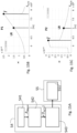
- FIG. 1A to this regard it is shown an example of PMUT transducer 1000 comprising a membrane 1010 coupled with a thin piezoelectric film 1020.
- the upper portion of Figure 1A shows the deflection upwards of the membrane 1010 and piezoelectric film 1020 when a positive voltage is applied o between a top electrode 1030 and a metallic layer 1050 forming the bottom electrode coupled to the bottom surface of the piezoelectric film 1020 and to ground.
- the lower portion of Figure 1A shows the deflection downwards of the membrane 1010 and piezoelectric film 1020 when a negative voltage is applied.
- the mechanical system represented by the membrane 1010 and film 1020 is intended.
- all the lumped parameters described in the following are referred to the fundamental mode, therefore they are modal parameters (stiffness, ⁇ and RLC branch in Figure 5 ).
- the other normal modes may be not considered under the assumption that they are not excited when working at frequencies close to the natural frequency of the fundamental mode.
- the functional diagram of Figure 1B refers by way of example to ultrasound-based obstacle detection and ranging which may include (in a manner known to those of skill in the art) an electrical transmission signal TX applied to a transmission pulse generator 10 (a PMUT-based generator for instance) which is configured to emit corresponding acoustical pulses (ultrasound pulses) towards a surrounding space, for instance as input voltage V IN,TX , with a given input frequency f IN .
- a transmission pulse generator 10 a PMUT-based generator for instance
- V IN,TX input voltage
- f IN input frequency
- a reference signal such as a reference echo RE.
- a reference signal can be generated (as discussed in the following) in an operation represented by block 50 with envelope extraction possibly applied (as represented at 60 in dashed line) to the reference echo RE.
- the outcome of cross-correlation of the received signal and the reference signal RE at block 40 may produce a measurement signal MS to be used for a desired application (obstacle detection and ranging, for instance).
- the measurement signal MS resulting from cross-correlation shows as a function of time a cross-correlation peak or peaks, which may correspond to obstacles reflecting the ultrasound pulses at different position.
- the time coordinate of the peak indicates the time-of-flight of the pulses, from which it can be obtained the distance, knowing the speed of the acoustic pulses.
- a possible TX/RX obstacle detection/ranging arrangement is just exemplary of a wide variety of possible applications (volume measurement, gesture recognition, flow metering, just to mention a few), which may possibly include only a "transmitter” section and/or only a “receiver” section.
- Such Reference Echo Synthesis is based on a linear model and shows limitations related to non-linear mechanical response, in the first place a limited range, caused by saturation of sound pressure level, when increasing the driving voltage. Also, it has a reduced accuracy, caused by applying a linear model to a non-linear system.
- a non-linear response is typical of this type of transducers, because the radius to thickness ratio of the membrane is quite high.
- An object of one or more embodiments is to contribute to further improving operation of electro-acoustic transducers by addressing certain issues such as a limited range, caused by saturation of sound pressure level, when increasing the driving voltage and reduced accuracy, caused by applying a linear model to a non-linear system.
- One or more embodiments may relate to a corresponding device (an acoustic location sensor module being exemplary of such a device).
- One or more embodiments may relate to a corresponding system.
- Obstacle detection systems for use in the automotive field, for instance
- volume measurement systems for use in the automotive field, for instance
- gesture recognition systems for use in the automotive field, for instance
- flow metering systems are exemplary of such systems.
- references to "an embodiment” or “one embodiment” in the framework of the present description is intended to indicate that a particular configuration, structure, or characteristic described in relation to the embodiment is comprised in at least one embodiment.
- phrases such as “in an embodiment” or “in one embodiment” that may be present in one or more points of the present description do not necessarily refer to one and the same embodiment.
- particular conformations, structures, or characteristics may be combined in any adequate way in one or more embodiments.
- electro-acoustic transducers that is components capable of acting as transducers between the electrical domain and the acoustical domain, by converting electrical signals into acoustic signals -- and/or -- converting acoustic signals into electrical signals; that is, the wording "electro-acoustic" is in no way to be construed, even indirectly, as limited to converting electrical signals into acoustic signals.
- TX transmitter
- RX receiver
- the embodiments are not limited to such possible TX/RX arrangements and can be advantageously applied to arrangements including only a "transmitter” section (to controllably adjust the resonance frequency of a transducer therein, for instance) or only a “receiver” section (to generate a reference signal for cross-correlation with a signal received via a transducer therein, for instance).
- one or more embodiments may apply, in general, to electro-acoustic transducers capable of acting as transducers between the electrical domain and the acoustical domain.
- PMUTs will be referred throughout for simplicity and ease of understanding, the embodiments can be advantageously applied to electro-acoustic transducers other than PMUTs where issues such as those discussed in the foregoing may arise.
- TX transmission
- RX reception
- One or more embodiments may be based on the recognition that the resonance frequency of a transducer as considered herein (and other parameters, such as parameters exemplary of the damping behavior of the vibrating part of the transducer, such as the membrane of a PMUT, for instance) can be identified as schematically exemplified in Figure 2 , namely by sensing the transducer response to (electrical) stimulation pulses (see TX pulses on the left-hand side of Figure 2 ).
- damping ratio the decay time constant or the Q-factor are exemplary of such "damping parameters" representative of the damping behavior of a transducer.
- Figure 2 is exemplary of the operation of sensing the ring-down behavior of a transducer (namely how the pulses gradually "die-down” once the stimulation pulses are discontinued), as indicated on the right-hand side of Figure 2 .
- the damping ratio or the Q-factor representative of how the amplitude of the oscillation reduces over time during ring-down, eventually going to zero, can be used in embodiments.
- Figure 4 is exemplary of the possibility of providing an "electrical" representation of an oscillating system
- BVD model Bitworth-Van Dyke model
- a capacitor Co arranged in parallel with a RLC branch comprising the series of a resistor R, an inductor L and another capacitor C, to which the following relationships may apply:
- I RLC indicates the current in RLC (series) branch at the beginning of ringdown.
- the Butterworth-Van Dyke model (also known as a "Mason” or “KLM” model) is an electrical equivalent circuit of an electro-acoustical transducer comprising, as schematically represented in Figure 5 , an electrical domain ED coupled, via an electrical-mechanical coupling EMC, a mechanical domain MD (notionally having plural normal modes: only the first one is represented in Figure 5 for simplicity).
- the mechanical domain MD is in turn coupled, via a mechanical-acoustic coupling MAC, to an acoustic domain AD.
- the electrical domain ED can be represented as a capacitor Co across a first (primary, for instance) winding of a first transformer modeling the electrical-mechanical coupling EMC, with an (electrical) signal V applied across the capacitor Co and the winding of the transformer.
- V may be a generator (that is, an input, as may be the case of ES in Figure 6A ) or a measuring unit (that is, an output as may be the case of SM in Figure 6B ).
- the mechanical domain MD comprises the other (secondary, for instance) winding of the transformer which models the electrical-mechanical coupling EMC and a first (primary, for instance) winding of a (second) transformer modeling the mechanical-acoustic coupling MAC coupled in a loop including the series connection of a resistor b m modeling internal losses, an inductor m m modeling the (vibrating) mass (a membrane, for instance) and a capacitor modeling the stiffness 1/k thereof.
- the acoustic domain AD comprises the other (secondary, for instance) winding of the transformer which models the electrical-mechanical coupling EMC included in a loop together with a generator which models the sound pressure level p in possibly incident onto the transducer and an impedance Z a which models the (air) acoustic impedance.
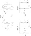
- the model can be simplified by removing the transformers EMC, MAC, which results in simplified models for a transmitter transducer (electric to acoustic) and for a receiver transducer (acoustic to electric) as represented in Figure 6A and Figure 6B , respectively, where parts or elements like parts or elements already discussed in connections with the previous figures are indicated by like reference symbols.
- ES represents an (electrical) excitation signal (TX in Figure 1 , for instance) applied to a transmitter transducer (10 in Figure 1 , for instance) which results in a current A indicative of (proportional to) the (ultra)sound pressure level generated by the transducer.
- PV represents a voltage indicative of (proportional to) the incident (ultra)sound pressure level (as received at 20 in Figure 1 , for instance) and SM denotes a measured (voltage) signal.
- the ability of identifying the resonance frequency of an electro-acoustical transducer may be exploited in order to obtain that a certain transducer may operate at a desired resonance frequency.
- a transducer membrane possibly having different and time-varying resonance frequencies, for instance at a transmitter (block 10 in Figure 1 ) and at a receiver (block 20 in Figure 1 ) may adversely affect operation of a related arrangement, by possibly making is unsatisfactory, if not hardly possible.
- the ability to identify the resonance frequency of an electro-acoustical transducer may be exploited as schematically exemplified in Figure 7 , that is by exploiting the dependency of a piezo-electric layer stiffness (and thus the resonant behavior of the associate transducer) on a (DC) bias voltage V BIAS applied to the transducer UT.
- this may occur via a bias generator BG controlled by a regulator RG configured to selectively vary the resonance frequency of the transducer UT as a function of the offset (difference) calculated at a comparison node CN between a setpoint oscillation frequency f 0,ref (corresponding to a desired resonance frequency, for instance) and an actual resonance frequency f 0,m as measured on the transducer UT via a measurement unit MU.
- a bias generator BG controlled by a regulator RG configured to selectively vary the resonance frequency of the transducer UT as a function of the offset (difference) calculated at a comparison node CN between a setpoint oscillation frequency f 0,ref (corresponding to a desired resonance frequency, for instance) and an actual resonance frequency f 0,m as measured on the transducer UT via a measurement unit MU.
- the measurement unit MU can be configured to measure the actual resonance frequency f 0,m with a view to bringing the resonance frequency of the electro-acoustical transducer (UT) to a reference frequency value (for instance as discussed in connection with Figure 7 , for instance, that is by controlling a bias voltage V BIAS of the electro-acoustical transducer as a function of the resonance frequency).
- a (closed loop) control system as exemplified in Figure 7 is the representation of the control with transfer functions assigned to each block (continuous or discrete time). Some of these blocks may not be not physical, but may be software computations (e.g., CN, RG, part of MU), while the bias generator BG and the transducer UT are usually physical blocks.
- the ability of identifying the resonance frequency may be exploited as schematically represented in Figures 8A and 8B (substantially similar to Figures 6A and 6B , but here considered in possible combination) in order to generate -- in real time -- a desired expected shape for a reference signal RE (a reference echo as exemplified in Figure 1 , for instance).
- Figures 8A and 8B are exemplary of a case applicable to an arrangement as exemplified in Figure 1 where, once the BVD model parameters are known (for the transmitter at 10 and for the receiver at 20) an expected echo shape RE can be calculated, for instance with numerical integration.
- the expected waveform of the (ultra)sound signal generated by the transmitter transducer can be calculated, as modeled by the current I TX of the current generator A of Figure 8A .
- the receiver transducer can be represented as a BVD model with constant k being able to be whatever insofar as the output V out is normalized.
- analog front end AFE Taking into account the analog front end AFE is helpful insofar as the analog front end (a trans-impedance amplifier with a low-pass filter can be considered as a non-limiting example) may have an impact on the output waveform.
- Such synthesis may involve calculations (essentially, numerical integration of the BVD model based on principles known to those of skill in the art) suited to be performed on-the-fly (that is in real time) in a processing unit.
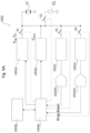
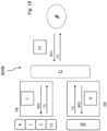
- the diagram of Figure 9A refers to a hardware architecture intended for use with a single transducer UT (and intended to be replicated for every transducer in a system), although in variant embodiments architecture with plural transducers, a transmitter transducer TX UT and a receiver transducer RX UT, for instance, are possible.
- references 1004a and 1004b denote a controller circuit and a memory circuit which, in one or more embodiments, may be included and/or associated with the processing unit (MCU, for instance) 1004 in Figure 19 .
- MCU processing unit
- blocks 1002a to 1002d are exemplary of circuitry adapted to be included in the analogue portion 1002 exemplified in Figure 19 .
- reference 1002a denotes AC voltage generators (for instance pulse generator of the AC-coupled type) adapted to apply electric pulses to the transducer(s) UT or TX UT, RX UT both for transmission pulse generation (see block 10 in Figure 1B ) when coupled to the transducer(s) via switches such as S1.
- Their output is an input voltage V IN , with an amplitude A IN and input frequency f IN .
- both the generator(s) 1002a and the switch S1 are configured to operate under the control of the controller 1004a.
- Reference 1002b in Figure 9A denote DC voltage generators (DC coupled) configured to apply to the transducer(s) UT or TX UT, RX UT DC bias, such as, for instance the (control) bias voltage V BIAS of Figure 7 .
- reference 1002c denotes an amplifier/buffer adapted to be coupled to the transducer UT (or a respective one of the transducers TX UT, RX UT) via a switch S3 operating under the control of the controller 1004a.
- Reference 10020c denotes an analogue-to-digital converter (ADC) configured to convert to the digital domain a signal as produced by the amplifier 1002c during ring-down acquisition (see the right-hand side of Figure 2 or operation FT in Figure 10 ) and block FT in Figure 10 .
- ADC an analogue-to-digital converter
- Reference 1002d denotes another amplifier (a trans-impedance amplifier, for instance) configured to be selectively coupled to the transducer UT or RX UT during acquisition of the received signal (see block 20 in Figure 1 and block RD3 in Figure 10 described in the following).
- a trans-impedance amplifier for instance
- Reference 10020d denotes an analogue-to-digital converter (ADC) configured to convert to the digital domain a signal as produced by the amplifier 1002d (which is configured to be coupled to the transducer(s) UT ( Figures 14A ) or RX UT ( Figures 14B and 14C) via a switch S4 controlled by the controller 1004a.
- ADC an analogue-to-digital converter
- reference CL in Figure 9A denotes an (optional) clamp load configured to be coupled to the transmitter transducer(s) via a switch S2 controlled by the controller 1004a during measurement in order to facilitate quick dampening of transducer oscillations.
- the value for the clamp load CL may be selected as an impedance value which facilitates transfer of energy from the transducer to the load CL.
- CL may be a resistor with a value equal to the modulus of the impedance for Co in Figure 8A .
- the following Table is exemplary of possible criteria which may be adopted in the controller 1004a (configured to be programmed for that purpose in a manner known to those of skill in the art) to control the switches S1 to S4 in possible embodiments.
- the switches shown may not be actual, “physical” switches (MOSFET transistors, for instance). In one or more embodiments, the switches shown may be implemented with series impedances, for instance.
- Figure 9B is an exemplary representation against a common time scale t of transmitter identification TX ID, receiver identification RX ID and measurement MS phases with exemplary representation of activation of:
- FIG 10 it is described a diagram exemplary of procedures which, as illustrated in the following are used within operations of the method here described, in particular the diagram is exemplary of an operation RD performed by a control unit of the system to find an oscillation frequency f 0,m , i.e. the natural frequency of the membrane 1010, on the basis of a ringdown signal and of an operation FT of frequency tuning.
- an oscillation frequency f 0,m i.e. the natural frequency of the membrane 1010
- Operation RD to find the natural frequency includes first applying pulse excitation RD1 to the transducer, receiver or transmitter, followed by ring-down acquisition RD2 for the excited sensor, i.e. the membrane as receiver or transmitter.
- the results of ring-down acquisition RD2 can thus be exploited (as discussed previously) for identifying RD3 transducer parameters such as the oscillation frequency fo and also the decay constant ⁇ .
- the sequence of operations RD1, RD2, RD3 of Figure 10 as mentioned represents the operations to measure the natural frequency fo of a membrane 1010.
- FIG 10 is represented also the frequency tuning operation FT which may be then performed on the transducer, receiver or transmitter or same transducer operating as transmitter and receiver, using as set point the frequency f 0,ref .
- the measured oscillation frequency f 0,m is shown as provided by the operation RD on the basis of the ringdown signal.
- Frequency tuning FT performs the closed control loop shown with reference to Figure 7 , using the measured oscillation frequency f 0,m from operation RD in order to have the measured frequency f 0,m converge to the value of the set point f 0,ref .
- the frequency tuning FT is exemplary of an operation which includes performing a number of iterations of the loop of Figure 7 (blocks CN, RG, BG, UT) to have the measured frequency f 0,m converge to the value of the set point frequency f 0,ref , the loop also controlling and determining consequently the value of the bias voltage V BIAS .
- Figure 11 it is shown a diagram representing the modal stiffness k of the membrane 1010 and of the piezoelectric 1020 together as a function of its displacement x from a rest position.
- the tangent of the non-linear curve of modal stiffness k in the rest position with prestress P2 may be calculated by an approximation with Duffing-Helmholtz equation (quadratic term only). It is here specified that the position is not actually without stress, the pre-stress cannot be removed, but the pre-stress may be somehow counterbalanced by the static force induced by the piezoelectric material. Thus, in the following it will be referred as position with balanced pre-stress.
- the modal stiffness k is represented as a function of the displacement x by writing the Taylor series and keeping only the first two terms.
- this non-constant stiffness k is included in the harmonic oscillator equation that describes the fundamental vibrating mode, it is obtained the quadratic Duffing-Helmholtz equation.
- Parameter b represents the damping and c(x) the stiffness.
- the stiffness term c(x) is represented as a function of the displacement by writing the Taylor series and keeping only the first three terms, c 0 , c 1 , c 2 .
- a x ⁇ + b x ⁇ + c 0 + c 1 x + c 2 x 2 + c 3 x 3 + ⁇ x F t
- this equation is represented by the dynamical branch (RLC branch), where the capacitance C is not constant, but depends on accumulated charge.
- RLC branch dynamical branch
- the capacitances C of the RLC branch for the transmitter and the receiver are not constant, but function of accumulated charge Q.
- Q represents the charge
- ⁇ indicates the second order term or coefficient of the electric equivalent of the stiffness term c(x), i.e. corresponding to coefficient c 2 in the Duffing-Helmholtz equation with c(x) expanded with Taylor series keeping only the first three terms, c 0 , c 1 , c 2
- ⁇ is the first order term, indicated in the following as non-linear parameter, corresponding to coefficient c 1 in the Duffing-Helmholtz equation with c(x) expanded with Taylor series keeping only the first three terms, c 0 , c 1 , c 2 .
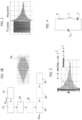
- Figure 12 it is shown then a diagram where it is represented the displacement x of the membrane 1010 of the transmitter as a function of the input frequency f IN of the transmitter.
- Several curves are shown each corresponding to a different value of input amplitude A IN of the input voltage V IN,TX .
- the arrow indicates increasing values of input amplitude A IN , from 0,1 to 3.0 Vpp.
- LD is indicated an operating point where system is operated at large displacement x values as it was linear, it still works, but with reduced accuracy.
- NLD is indicated an operating point with non-linear operation with a much higher power output.
- the method here described basically considers that in the linear system (small displacements) the optimal operating point is at resonance. It is desirable to increase the TX output power as much as possible, which requires large displacements at which the TX transducer is no more linear, while the RX transducer remains linear (always small displacements). Thus, if the system is operated at large displacements as it was linear (point LD), it still works, but with reduced accuracy. However, there is another operating mode where the TX output power PTX is much higher, in the region of non-linear operating point NLD. Moreover, if a proper non-linear model is used for reference echo prediction, accuracy is improved.
- FIG. 13 it is shown a flow diagram describing an embodiment of the operation of generation of a reference echo RE 50 of Figure 1B , which comprises the following operations:
- the reference echo RE is indeed the output of the last block, however the procedure in Figure 13 also finds the optimal operating point f ⁇ and sets up the system to work at that operating point f ⁇ .
- the parameter ⁇ in the Duffing-Helmholtz equation can be written as function of the non-linear parameter ⁇ , to reduce the complexity of identification of non-linear parameters, from two to one: L ⁇ 2 Q ⁇ t 2 + R ⁇ Q ⁇ t + 1 C 1 + ⁇ Q + ⁇ Q 2 Q ⁇ L ⁇ 2 Q ⁇ t 2 + R ⁇ Q ⁇ t + 1 C 1 + ⁇ Q + f ⁇ Q 2 Q
- the stiffness k vs. displacement x function is symmetric. This is the operating point where the membrane 1010 is flat, while at point P2, with a stress applied, the stiffness k is no longer symmetric with respect to point 2.
- k(x) k 2 (1 + ⁇ x + ⁇ x 2 )
- k 1 is also the vertex of the parabola.
- Steps 52R for the receiver and 52T for the transmitter are performed using the steps RD1, RD2, RD3 to find respective oscillation frequencies f 0R , for and time decay values ⁇ R , ⁇ T .
- tuning 53 operates according to the tuning operation FT described in Figure 10 and Figure 7 above using the oscillation frequency of the receiver f 0R as setpoint frequency for the loop.
- the control unit of the system chooses the setpoint frequencies for the tuning loops (i.e. f 0,ref in Fig.7 ), based on values of oscillation frequencies f 0R , f 0T .
- Operation 53 represents the frequency tuning of the receiver and/or transmitter membrane: frequency tuning is performed on one of them (more generally, on both of them) in order to have them resonating at the same natural frequency. This is required before performing operation 54.
- operation 53 includes performing a frequency tuning FT respectively on the transmitter and the receiver on the basis of said respective oscillation frequencies f 0R , for, this in particular comprising supplying said respective oscillation frequencies f 0R , f 0T to a corresponding loop, e.g. CN, RG, BG, MU of Figure 7 , updating a regulation block RG, which is its turn updates a bias generator BG.
- a frequency tuning FT respectively on the transmitter and the receiver on the basis of said respective oscillation frequencies f 0R , for, this in particular comprising supplying said respective oscillation frequencies f 0R , f 0T to a corresponding loop, e.g. CN, RG, BG, MU of Figure 7 , updating a regulation block RG, which is its turn updates a bias generator BG.
- Figure 15A it is shown then a flow diagram of the operations 54 and 55.
- Figures 15B and 15C show diagram representing displacement x as a function of the input frequency f IN,TX , at a maximum value of amplitude of the input voltage, in the example 3.0 VPP, in the case of starting from point P1 (no-prestress) and point P2 (prestressed membrane) respectively.
- Operation 54 includes therefore a step 541 of setting the amplitude of the input voltage V IN at a maximum value A INmax , e.g. 3.0 VPP. Subsequently, in a step 542 it is performed sweeping the input frequency of the transmitted f IN,TX around linear resonance, indicated by LR in Figures 15B, 15C . At each frequency point it is measured the ring-down amplitude, in terms of displacement x, thus obtaining a values x (f IN,TX ) , such as those shown in Figures 15B, 15C .
- the step of performing 55 a frequency tuning on the receiver corresponding to operation FT using at such frequency estimate f ⁇ as setpoint frequency f 0,ref as exemplified in Figure 7 with a corresponding update regulation and an update of bias generator.
- the sequence RD1, RD2, RD3 in operation RD represents the operations to measure the natural frequency of a membrane 1010.
- a control unit of the system performs this sequence, e.g., in 52T, 52R, and within operations 51, 53, 54, 55 (and MU).
- frequency tuning operations such as in operations 53 and 56 are performed comprising tuning operation FT according to Figure 10 exploiting the loop of Figure 7 .
- Operations RD, FT are in general applied a single membrane, regardless its usage as transmitter or receiver.
- the transducer may have a single membranate, operating for transmission and reception.
- V BIAS bias voltage
- operations 57 of identification of the non-linear parameter ⁇ is detailed in the flow diagram of Figure 16 , and may be performed using an ad-hoc Neural Network, and includes first exciting 571 with a high voltage, corresponding to the non-linear operation zone, at the oscillation frequency and acquire the corresponding ring down (using for instance operation RD), then computing 572 the period T from the ring down, then feeding 573 a trained neural network with the period curve T(t), R, L, C and initial value of the ringdown IC, finally computing 574 the non-linear parameter ⁇ with the trained neural network.
- the non-linear parameter is the first order coefficient in the electrical equivalent model of the Duffing Helmholtz equation, represented by the dynamical branch (RLC branch), where the capacitance C is not constant, but depends on accumulated charge.
- RLC branch dynamical branch
- the non-linear parameter ⁇ is the first order term of the electrical equivalent of stiffness c(x), i.e. corresponding to coefficient c 1 in the Duffing-Helmholtz equation with c(x) expanded with Taylor series keeping only the first three terms, c 0 , c 1 , c 2 .
- second order parameter ⁇ may be comprised in the non-linear parameter determined by the operation 57.
- Figure 16 are also shown the operation 575, 576 of a training procedure of the neural network, which of course is performed only once offline, not during the normal operation of the transducer.
- 575 is indicated the generation of an artificial data set, with 576 the training of the neural network with such dataset.
- an artificial data set 575 i.e. a training data set
- generation of an artificial data set 575 is performed by numerical integration of the Duffing model equation, with a choice of the parameters in accordance with the measurements. It is then trained 576 the ad-hoc Neural Network AHN that takes period curves T(t) and differential equation parameters as input and gives the predicted non-linear parameter ⁇ . Then, the so trained network is used for computing 574 non-linear parameter ⁇ with the trained neural network
- Trained on an artificial dataset generated from the numerical integration of the model equation avoids needing to collect a labelled dataset that would be impossible to obtain in this particular scenario, as the parameter ⁇ is always unknown.
- the main advantage of this approach is that the networks are capable to learn a more general identification function that could be applied to different membranes and spare the time to obtain a large number of acquisitions.
- Hybrid networks have branches that take as input different data type, process them separately and then concatenate them together to produce the output. In this way we can process all the relevant features of the device together despite their format.
- the first branch of the network AHN accepts as input the numerical parameters and processes them with few fully connected layers, while the other branch processes the period curve with a DNN (e.g. CNN or RNN).
- the outputs of the two branches are subsequently concatenated and processed with other fully connected layers. At this point the target ⁇ is computed.
- FIG 17 it is shown the trained neural network AHN, an ad-hoc network with hybrid architecture.
- Hybrid networks have branches that take as input different data type, process them separately and then concatenate them together to produce the output. In this it is possible to process all the relevant features of the device together despite their format.
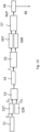
- a first branch FB of the network AHN accepts as input the numerical parameters R, L, C and IC and processes them with few fully connected layers in a feed forward neural network FFN indicated with F, while another other branch DB processes the period curve T(-t) with a deep neural network DNN (e.g. convoluted neural network CNN or recurrent neural network RNN) indicated with D.
- DNN e.g. convoluted neural network CNN or recurrent neural network RNN
- prediction 58 of the reference echo is performed, using a TX-RX chain model based on modified Butterworth-Van-Dyke model, including non-constant stiffness, i.e. non-linear parameter ⁇ , determining a BVD model for a transmitter transducer and a receiver transducer (starting from reference parameters f 0,TX , ⁇ TX and f 0,RX , ⁇ RX for a transmitter transducer and a receiver transducer, respectively).
- Model parameters are computed from ring-down waveform, in previous steps
- the waveform of expected received echo RE is synthesized, in particular computed by numerical integration of the whole TX-RX chain, along the lines indicated in Figures 8A, 8B , providing the reference RE as an output.
- non-linear parameters may not be considered, i.e. Reference Echo Prediction 58 is made using linear model. Thus steps 51 and 57 are not performed. In other variant embodiments, no model identification may be performed, using nominal waveform for Cross-Correlation 40. Thus steps 51 and 56-58 are not performed.
- the parameter ⁇ in the BVD-Duffing model can be computed with a MSE (Minimum Squared Error) optimization on period curves T(t), instead of using a Neural Network. It is found an optimal parameter value ⁇ opt such that the MSE between the period of the measurements and of the integrated model with the optimal parameter value ⁇ opt is small.
- the parameter ⁇ is computed in two steps:
- Figure 19 is exemplary of a circuit/system architecture configured to host (at 1004, for instance) a software procedure capable of performing time-of-flight measurements by means of one or more ultrasonic transducers UT by taking into account (and countering) possible drawbacks related to narrow bandwidth available and/or transducer parameters possibly subject to manufacturing spread and variations over time.
- This may occur by means of a hardware architecture 1002 suited to connect one or more transducers UT to a DC voltage generator 1002b and (simultaneously) to either one of AC voltage generator (1002a), a trans-impedance amplifier (1002d), an amplifier/buffer (1002c) and a clamp load (L) by avoiding undesired mutually interference.
- a method of operating a PMUT electro-acoustical transducer may comprise:
- said sweeping an input frequency of the transmitter to find a frequency of the maximum displacement in the ringdown signal includes setting the amplitude of the input voltage at a maximum value, sweeping the input frequency of the transmitter in a linear resonance region, measuring the corresponding ring-down amplitudes, in terms of membrane displacement, finding a frequency (f) of the maximum displacement when the ringdown amplitude values (x) is maximum, performing a frequency tuning of the receiver at said frequency of the maximum displacement in the ringdown signal of the transmitter.
- the method may further comprise performing the identification of the parameters of the transmitter and the receiver,
- the method may further comprise sweeping the value of the bias voltage of the transmitter finding a minimum value of the oscillation frequency associated to an operating point with balanced pre-stress and obtaining a resonance frequency associated to an operating point with pre-stress from the transmitter ringdown, performing a parameter reduction in the Duffing Helmholtz equation as a function of said minimum value of the oscillation frequency associated to an operating point with balanced pre-stress and resonance frequency associated to an operating point with pre-stress,
- the method may further comprise performing a frequency tuning respectively on the transmitter and the receiver on the basis of said respective oscillation frequencies, comprises supplying said respective oscillation frequencies to a corresponding loop (CN, RG, BG, MS) updating a regulation block, which is its turn updates a bias generator,
- said performing the identification of the one or more non-linear parameters of the transmitter and the receiver includes performing an identification with a Butterworth-Van Dyke model on the basis of the transducer parameters including the oscillation frequency of the transmitter or receiver and also the decay constant of the transmitter or receiver obtained by finding an oscillation frequency of the transmitter on the basis of a transmitter ringdown signal and finding an oscillation frequency of the receiver on the basis of a receiver ringdown signal.
- said performing an identification of one or more non-linear parameters of the transmitter includes
- said network may comprise a first branch accepting as input the series parameters of the BDV model and an initial value of the ringdown and processes them with fully connected layers in a feed forward network and a second branch accepting as input the period curve T and processing it with a deep neural network, the outputs of the two branches being subsequently concatenated and processed with a further fully connected layers in a feed forward network,
- a circuit may comprise:
- a device comprising a circuit according to embodiments, the device selected out of
- a circuit as exemplified herein may comprise control circuitry (for instance, CN, RG, BG) configured to control a bias voltage of the at least one electro-acoustical transducer as a function of the resonance frequency calculated to bring the resonance frequency of the electro-acoustical transducer to a reference frequency value.
- control circuitry for instance, CN, RG, BG
- a circuit as exemplified herein may be configured (via a same or different receiver transducer) to transduce an acoustical signal received into an electrical reception signal with said signal processing circuitry configured to calculate, as a function of said ring-down signal, a damping parameter of the electro-acoustical transducer, and synthesize, as a function of the resonance frequency and the damping parameter of the electro-acoustical transducer calculated, a cross-correlation reference signal,
- cross-correlation circuitry (for instance, 40) may be provided to perform cross-correlation of the electrical reception signal and the cross-correlation reference signal.
- the method here described allows to obtain an increased range of the time-of-flight measure, in particular thanks to the capability to measure and predict the non-linear response, the transmitter can be driven with increased range, thanks to increased emitted sound pressure, with the same (bounded) voltage of prior art solutions, and the representation of the expected echo is more accurate (increased accuracy).
- the maximum driving voltage is bounded by either the driving circuitry (e.g. to keep power consumption/dimension/cost low/small) or the transducer (related to the maximum electric field that piezo material can withstand without damage), thus the method here described allows increasing the output pressure (and therefore the range) despite the bounded input voltage.
Landscapes
- Engineering & Computer Science (AREA)
- Physics & Mathematics (AREA)
- Remote Sensing (AREA)
- Radar, Positioning & Navigation (AREA)
- Computer Networks & Wireless Communication (AREA)
- General Physics & Mathematics (AREA)
- Acoustics & Sound (AREA)
- Signal Processing (AREA)
- Mechanical Engineering (AREA)
- Otolaryngology (AREA)
- General Health & Medical Sciences (AREA)
- Health & Medical Sciences (AREA)
- Measurement Of Velocity Or Position Using Acoustic Or Ultrasonic Waves (AREA)
- Selective Calling Equipment (AREA)
Applications Claiming Priority (1)
| Application Number | Priority Date | Filing Date | Title |
|---|---|---|---|
| IT102022000000464A IT202200000464A1 (it) | 2022-01-13 | 2022-01-13 | Procedimento di operazione di trasduttori elettroacustici, corrispondente circuito e dispositivo |
Publications (2)
| Publication Number | Publication Date |
|---|---|
| EP4212909A1 true EP4212909A1 (fr) | 2023-07-19 |
| EP4212909B1 EP4212909B1 (fr) | 2025-10-15 |
Family
ID=80999542
Family Applications (1)
| Application Number | Title | Priority Date | Filing Date |
|---|---|---|---|
| EP22213083.3A Active EP4212909B1 (fr) | 2022-01-13 | 2022-12-13 | Procédé de fonctionnement de transducteurs électroacoustiques, circuit et dispositif correspondants |
Country Status (4)
| Country | Link |
|---|---|
| US (1) | US12422536B2 (fr) |
| EP (1) | EP4212909B1 (fr) |
| CN (1) | CN116550585A (fr) |
| IT (1) | IT202200000464A1 (fr) |
Families Citing this family (4)
| Publication number | Priority date | Publication date | Assignee | Title |
|---|---|---|---|---|
| EP4545915A1 (fr) * | 2023-10-23 | 2025-04-30 | Kamstrup A/S | Débitmètre à ultrasons et procédé d'évaluation de l'état d'un milieu à l'intérieur d'un débitmètre à ultrasons |
| WO2025122277A1 (fr) * | 2023-12-06 | 2025-06-12 | The Penn State Research Foundation | Réseau ultrasonore étirable étroitement conditionné fabriqué avec ingénierie de charge de surface pour un geste sans contact et une détection de matériaux |
| US12615473B1 (en) * | 2023-12-13 | 2026-04-28 | Amazon Technologies, Inc. | Device-specific calibration for ultrasound emissions |
| CN120611680B (zh) * | 2025-05-28 | 2026-01-23 | 北京建筑大学 | 一种基于压电夹芯梁等效电路的模型构建方法及系统 |
Citations (2)
| Publication number | Priority date | Publication date | Assignee | Title |
|---|---|---|---|---|
| EP3103191B1 (fr) * | 2014-02-07 | 2018-07-11 | The Regents of the University of California | Réglage de la fréquence d'accord et/ou poursuite en fréquence d'un système mécanique de faible sensibilité à la traversée électrique |
| US20200292684A1 (en) | 2019-03-12 | 2020-09-17 | Stmicroelectronics S.R.L. | Method of operating electro-acoustic transducers, corresponding circuit and device |
Family Cites Families (20)
| Publication number | Priority date | Publication date | Assignee | Title |
|---|---|---|---|---|
| IT1060416B (it) * | 1975-05-23 | 1982-08-20 | Rca Corp | Circuito pilota di un trasduttore per un trasmettitore di comando a distanza |
| US5335545A (en) | 1990-09-04 | 1994-08-09 | Magnetrol International, Inc. | Ultrasonic detector with frequency matching |
| US5267219A (en) | 1992-07-17 | 1993-11-30 | Milltronics Ltd. | Acoustic range-finding system |
| US6731569B2 (en) | 2001-03-16 | 2004-05-04 | Automotive Technologies International Inc. | Methods for reducing ringing of ultrasonic transducers |
| EP1045613B1 (fr) | 1999-04-14 | 2005-06-29 | Matsushita Electric Industrial Co., Ltd. | Circuit de commande, transducteur acoustique électromécanique et dispositif terminal portatif |
| JP4192672B2 (ja) | 2003-05-16 | 2008-12-10 | 株式会社日本自動車部品総合研究所 | 超音波センサ |
| US7775086B2 (en) | 2006-09-01 | 2010-08-17 | Ut-Battelle, Llc | Band excitation method applicable to scanning probe microscopy |
| US20100097891A1 (en) * | 2008-10-22 | 2010-04-22 | Nature Vision Inc. | Auto tune sonar system |
| US8860234B2 (en) * | 2011-01-03 | 2014-10-14 | The Boeing Company | Systems and methods for harvesting vibrational energy from vehicles |
| DE102011075484A1 (de) * | 2011-05-09 | 2012-11-15 | Robert Bosch Gmbh | Ultraschall-Messsystem mit verringerter minimaler Reichweite und Verfahren zum Detektieren eines Hindernisses |
| US9537677B2 (en) | 2012-01-16 | 2017-01-03 | Sensanna Incorporated | Individually identifiable surface acoustic wave sensors, tags and systems |
| EP2881181A1 (fr) * | 2013-12-09 | 2015-06-10 | ELMOS Semiconductor AG | Procédé de détermination de paramètres électriques d'un syntoniseur pour convertisseur à ultrasons |
| US9810778B2 (en) | 2015-09-14 | 2017-11-07 | Semiconductor Components Industries, Llc | Triggered-event signaling with digital error reporting |
| US10585178B2 (en) | 2015-10-21 | 2020-03-10 | Semiconductor Componenents Industries, Llc | Piezo transducer controller and method having adaptively-tuned linear damping |
| KR20170071121A (ko) | 2015-12-15 | 2017-06-23 | 현대오트론 주식회사 | 초음파 신호 최적화 장치 및 방법 |
| US10675001B2 (en) * | 2016-06-04 | 2020-06-09 | Otonexus Medical Technologies, Inc. | Apparatus and method for characterization of a ductile membrane, surface, and sub-surface properties |
| US10677902B2 (en) | 2017-07-26 | 2020-06-09 | Texas Instruments Incorporated | Excitation interval for ultrasonic transducer |
| US10768706B1 (en) | 2019-05-07 | 2020-09-08 | Google Llc | Determining an amplitude of a braking portion of a waveform of a driving voltage signal for a linear resonant actuator |
| CN113019870A (zh) * | 2019-12-24 | 2021-06-25 | 深圳开立生物医疗科技股份有限公司 | 超声换能器的谐振频率跟踪方法、装置及相关设备 |
| US11387624B2 (en) * | 2020-02-04 | 2022-07-12 | Analog Devices International Unlimited Company | Resonant laser driver |
-
2022
- 2022-01-13 IT IT102022000000464A patent/IT202200000464A1/it unknown
- 2022-12-13 EP EP22213083.3A patent/EP4212909B1/fr active Active
-
2023
- 2023-01-05 US US18/150,534 patent/US12422536B2/en active Active
- 2023-01-10 CN CN202310032532.2A patent/CN116550585A/zh active Pending
Patent Citations (2)
| Publication number | Priority date | Publication date | Assignee | Title |
|---|---|---|---|---|
| EP3103191B1 (fr) * | 2014-02-07 | 2018-07-11 | The Regents of the University of California | Réglage de la fréquence d'accord et/ou poursuite en fréquence d'un système mécanique de faible sensibilité à la traversée électrique |
| US20200292684A1 (en) | 2019-03-12 | 2020-09-17 | Stmicroelectronics S.R.L. | Method of operating electro-acoustic transducers, corresponding circuit and device |
Non-Patent Citations (3)
| Title |
|---|
| LUO GUO-LUN ET AL: "Airborne Piezoelectric Micromachined Ultrasonic Transducers for Long-Range Detection", JOURNAL OF MICROELECTROMECHANICAL SYSTEMS, IEEE SERVICE CENTER, US, vol. 30, no. 1, 2 December 2020 (2020-12-02), pages 81 - 89, XP011833618, ISSN: 1057-7157, [retrieved on 20210120], DOI: 10.1109/JMEMS.2020.3037298 * |
| RICHARD J PRZYBYLA ET AL: "In-Air Rangefinding With an AlN Piezoelectric Micromachined Ultrasound Transducer", IEEE SENSORS JOURNAL, IEEE, USA, vol. 11, no. 11, 1 November 2011 (2011-11-01), pages 2690 - 2697, XP011363324, ISSN: 1530-437X, DOI: 10.1109/JSEN.2011.2157490 * |
| YURI KUSANO ET AL: "Effects of DC Bias Tuning on Air-Coupled PZT Piezoelectric Micromachined Ultrasonic Transducers", JOURNAL OF MICROELECTROMECHANICAL SYSTEMS., vol. 27, no. 2, 12 February 2018 (2018-02-12), US, pages 296 - 304, XP055646136, ISSN: 1057-7157, DOI: 10.1109/JMEMS.2018.2797684 * |
Also Published As
| Publication number | Publication date |
|---|---|
| EP4212909B1 (fr) | 2025-10-15 |
| US20230221422A1 (en) | 2023-07-13 |
| US12422536B2 (en) | 2025-09-23 |
| IT202200000464A1 (it) | 2023-07-13 |
| CN116550585A (zh) | 2023-08-08 |
Similar Documents
| Publication | Publication Date | Title |
|---|---|---|
| EP4212909B1 (fr) | Procédé de fonctionnement de transducteurs électroacoustiques, circuit et dispositif correspondants | |
| US11579273B2 (en) | Method of operating electro-acoustic transducers, corresponding circuit and device | |
| Lefeuvre et al. | Semi-passive piezoelectric structural damping by synchronized switching on voltage sources | |
| KR100600807B1 (ko) | 에너지 포집형 표면탄성파 기반의 무전원/무선 센서 | |
| CN110180770B (zh) | 微机械超声换能器与制造和设计微机械超声换能器的方法 | |
| Smyth et al. | Analytic solution for N-electrode actuated piezoelectric disk with application to piezoelectric micromachined ultrasonic transducers | |
| US11641168B2 (en) | Parametric resonator for electrical transduction | |
| Glushkov et al. | Selective Lamb mode excitation by piezoelectric coaxial ring actuators | |
| Massimino et al. | Multiphysics modelling and experimental validation of an air-coupled array of PMUTs with residual stresses | |
| Massimino et al. | Air-coupled PMUT at 100 kHz with PZT active layer and residual stresses: Multiphysics model and experimental validation | |
| Lohfink et al. | Derivation of a 1D CMUT model from FEM results for linear and nonlinear equivalent circuit simulation | |
| Mattila et al. | Electroacoustic model for electrostatic ultrasonic transducers with V-grooved backplates | |
| Faiz et al. | Wave transmission reduction by a piezoelectric semi-passive technique | |
| US12000909B2 (en) | Measuring device for weak and slowly changing magnetic fields, in particular for biomagnetic fields | |
| CN121385854B (zh) | 超声测距芯片、超声测距装置及自适应阈值生成方法 | |
| KR101116165B1 (ko) | 병렬 랑지방 배열 압전소자 이용 초음파 변환기, 그 초음파 변환기의 제조방법, 그 초음파 변환기를 이용한 초음파 변환방법 | |
| Nastro et al. | Piezoelectric micromachined acoustic transducer with electrically-tunable resonant frequency | |
| Yadav et al. | Study on piezoelectric ceramic under different pressurization conditions and circuitry | |
| CN118646389B (zh) | 一种谐振器及自适应调谐方法 | |
| CN101800487B (zh) | 机械振动构件的电阻尼 | |
| Passoni et al. | Modeling, Identification and Operation of Air-Coupled PMUTs in Non-Linear Regime | |
| US20030081505A1 (en) | Acoustic transducer damping method | |
| Roes et al. | The effect of reflections on the performance of an acoustic energy transfer system | |
| Choe et al. | Ultrasonic distance measurement method by using the envelope model of received signal based on system dynamic model of ultrasonic transducers | |
| Bennett | Development of a finite element modelling system for piezocomposite transducers |
Legal Events
| Date | Code | Title | Description |
|---|---|---|---|
| PUAI | Public reference made under article 153(3) epc to a published international application that has entered the european phase |
Free format text: ORIGINAL CODE: 0009012 |
|
| STAA | Information on the status of an ep patent application or granted ep patent |
Free format text: STATUS: THE APPLICATION HAS BEEN PUBLISHED |
|
| AK | Designated contracting states |
Kind code of ref document: A1 Designated state(s): AL AT BE BG CH CY CZ DE DK EE ES FI FR GB GR HR HU IE IS IT LI LT LU LV MC ME MK MT NL NO PL PT RO RS SE SI SK SM TR |
|
| STAA | Information on the status of an ep patent application or granted ep patent |
Free format text: STATUS: REQUEST FOR EXAMINATION WAS MADE |
|
| 17P | Request for examination filed |
Effective date: 20240117 |
|
| RBV | Designated contracting states (corrected) |
Designated state(s): AL AT BE BG CH CY CZ DE DK EE ES FI FR GB GR HR HU IE IS IT LI LT LU LV MC ME MK MT NL NO PL PT RO RS SE SI SK SM TR |
|
| GRAP | Despatch of communication of intention to grant a patent |
Free format text: ORIGINAL CODE: EPIDOSNIGR1 |
|
| STAA | Information on the status of an ep patent application or granted ep patent |
Free format text: STATUS: GRANT OF PATENT IS INTENDED |
|
| INTG | Intention to grant announced |
Effective date: 20250711 |
|
| RIC1 | Information provided on ipc code assigned before grant |
Ipc: G01S 7/521 20060101AFI20250704BHEP Ipc: G01S 7/524 20060101ALI20250704BHEP Ipc: G01S 7/527 20060101ALI20250704BHEP Ipc: G01S 7/53 20060101ALI20250704BHEP Ipc: G01S 15/10 20060101ALI20250704BHEP |
|
| GRAS | Grant fee paid |
Free format text: ORIGINAL CODE: EPIDOSNIGR3 |
|
| GRAA | (expected) grant |
Free format text: ORIGINAL CODE: 0009210 |
|
| STAA | Information on the status of an ep patent application or granted ep patent |
Free format text: STATUS: THE PATENT HAS BEEN GRANTED |
|
| AK | Designated contracting states |
Kind code of ref document: B1 Designated state(s): AL AT BE BG CH CY CZ DE DK EE ES FI FR GB GR HR HU IE IS IT LI LT LU LV MC ME MK MT NL NO PL PT RO RS SE SI SK SM TR |
|
| REG | Reference to a national code |
Ref country code: GB Ref legal event code: FG4D Ref country code: CH Ref legal event code: F10 Free format text: ST27 STATUS EVENT CODE: U-0-0-F10-F00 (AS PROVIDED BY THE NATIONAL OFFICE) Effective date: 20251015 |
|
| REG | Reference to a national code |
Ref country code: DE Ref legal event code: R096 Ref document number: 602022023004 Country of ref document: DE |
|
| REG | Reference to a national code |
Ref country code: IE Ref legal event code: FG4D |
|
| PGFP | Annual fee paid to national office [announced via postgrant information from national office to epo] |
Ref country code: DE Payment date: 20251126 Year of fee payment: 4 |
|
| PGFP | Annual fee paid to national office [announced via postgrant information from national office to epo] |
Ref country code: AT Payment date: 20260113 Year of fee payment: 4 |
|
| REG | Reference to a national code |
Ref country code: NL Ref legal event code: MP Effective date: 20251015 |
|
| REG | Reference to a national code |
Ref country code: AT Ref legal event code: MK05 Ref document number: 1847387 Country of ref document: AT Kind code of ref document: T Effective date: 20251015 |
|
| PG25 | Lapsed in a contracting state [announced via postgrant information from national office to epo] |
Ref country code: NL Free format text: LAPSE BECAUSE OF FAILURE TO SUBMIT A TRANSLATION OF THE DESCRIPTION OR TO PAY THE FEE WITHIN THE PRESCRIBED TIME-LIMIT Effective date: 20251015 |
|
| PG25 | Lapsed in a contracting state [announced via postgrant information from national office to epo] |
Ref country code: ES Free format text: LAPSE BECAUSE OF FAILURE TO SUBMIT A TRANSLATION OF THE DESCRIPTION OR TO PAY THE FEE WITHIN THE PRESCRIBED TIME-LIMIT Effective date: 20251015 |
|
| REG | Reference to a national code |
Ref country code: LT Ref legal event code: MG9D |
|
| PG25 | Lapsed in a contracting state [announced via postgrant information from national office to epo] |
Ref country code: NO Free format text: LAPSE BECAUSE OF FAILURE TO SUBMIT A TRANSLATION OF THE DESCRIPTION OR TO PAY THE FEE WITHIN THE PRESCRIBED TIME-LIMIT Effective date: 20260115 |
|
| PG25 | Lapsed in a contracting state [announced via postgrant information from national office to epo] |
Ref country code: AT Free format text: LAPSE BECAUSE OF FAILURE TO SUBMIT A TRANSLATION OF THE DESCRIPTION OR TO PAY THE FEE WITHIN THE PRESCRIBED TIME-LIMIT Effective date: 20251015 Ref country code: FI Free format text: LAPSE BECAUSE OF FAILURE TO SUBMIT A TRANSLATION OF THE DESCRIPTION OR TO PAY THE FEE WITHIN THE PRESCRIBED TIME-LIMIT Effective date: 20251015 Ref country code: HR Free format text: LAPSE BECAUSE OF FAILURE TO SUBMIT A TRANSLATION OF THE DESCRIPTION OR TO PAY THE FEE WITHIN THE PRESCRIBED TIME-LIMIT Effective date: 20251015 |
|
| PG25 | Lapsed in a contracting state [announced via postgrant information from national office to epo] |
Ref country code: RS Free format text: LAPSE BECAUSE OF FAILURE TO SUBMIT A TRANSLATION OF THE DESCRIPTION OR TO PAY THE FEE WITHIN THE PRESCRIBED TIME-LIMIT Effective date: 20260115 |
|
| PG25 | Lapsed in a contracting state [announced via postgrant information from national office to epo] |
Ref country code: IS Free format text: LAPSE BECAUSE OF FAILURE TO SUBMIT A TRANSLATION OF THE DESCRIPTION OR TO PAY THE FEE WITHIN THE PRESCRIBED TIME-LIMIT Effective date: 20260215 |
|
| PG25 | Lapsed in a contracting state [announced via postgrant information from national office to epo] |
Ref country code: PT Free format text: LAPSE BECAUSE OF FAILURE TO SUBMIT A TRANSLATION OF THE DESCRIPTION OR TO PAY THE FEE WITHIN THE PRESCRIBED TIME-LIMIT Effective date: 20260216 |
|
| PG25 | Lapsed in a contracting state [announced via postgrant information from national office to epo] |
Ref country code: PL Free format text: LAPSE BECAUSE OF FAILURE TO SUBMIT A TRANSLATION OF THE DESCRIPTION OR TO PAY THE FEE WITHIN THE PRESCRIBED TIME-LIMIT Effective date: 20251015 |
|
| PG25 | Lapsed in a contracting state [announced via postgrant information from national office to epo] |
Ref country code: LV Free format text: LAPSE BECAUSE OF FAILURE TO SUBMIT A TRANSLATION OF THE DESCRIPTION OR TO PAY THE FEE WITHIN THE PRESCRIBED TIME-LIMIT Effective date: 20251015 |
|
| PG25 | Lapsed in a contracting state [announced via postgrant information from national office to epo] |
Ref country code: BG Free format text: LAPSE BECAUSE OF FAILURE TO SUBMIT A TRANSLATION OF THE DESCRIPTION OR TO PAY THE FEE WITHIN THE PRESCRIBED TIME-LIMIT Effective date: 20251015 |