EP4215664B1 - Système et procédé de traitement de textiles - Google Patents
Système et procédé de traitement de textiles Download PDFInfo
- Publication number
- EP4215664B1 EP4215664B1 EP22383272.6A EP22383272A EP4215664B1 EP 4215664 B1 EP4215664 B1 EP 4215664B1 EP 22383272 A EP22383272 A EP 22383272A EP 4215664 B1 EP4215664 B1 EP 4215664B1
- Authority
- EP
- European Patent Office
- Prior art keywords
- machine
- ozone
- gaseous mixture
- textiles
- humidity
- Prior art date
- Legal status (The legal status is an assumption and is not a legal conclusion. Google has not performed a legal analysis and makes no representation as to the accuracy of the status listed.)
- Active
Links
Images


Classifications
-
- D—TEXTILES; PAPER
- D06—TREATMENT OF TEXTILES OR THE LIKE; LAUNDERING; FLEXIBLE MATERIALS NOT OTHERWISE PROVIDED FOR
- D06B—TREATING TEXTILE MATERIALS USING LIQUIDS, GASES OR VAPOURS
- D06B9/00—Solvent-treatment of textile materials
-
- D—TEXTILES; PAPER
- D06—TREATMENT OF TEXTILES OR THE LIKE; LAUNDERING; FLEXIBLE MATERIALS NOT OTHERWISE PROVIDED FOR
- D06L—DRY-CLEANING, WASHING OR BLEACHING FIBRES, FILAMENTS, THREADS, YARNS, FABRICS, FEATHERS OR MADE-UP FIBROUS GOODS; BLEACHING LEATHER OR FURS
- D06L4/00—Bleaching fibres, filaments, threads, yarns, fabrics, feathers or made-up fibrous goods; Bleaching leather or furs
- D06L4/50—Bleaching fibres, filaments, threads, yarns, fabrics, feathers or made-up fibrous goods; Bleaching leather or furs by irradiation or ozonisation
-
- D—TEXTILES; PAPER
- D06—TREATMENT OF TEXTILES OR THE LIKE; LAUNDERING; FLEXIBLE MATERIALS NOT OTHERWISE PROVIDED FOR
- D06M—TREATMENT, NOT PROVIDED FOR ELSEWHERE IN CLASS D06, OF FIBRES, THREADS, YARNS, FABRICS, FEATHERS OR FIBROUS GOODS MADE FROM SUCH MATERIALS
- D06M11/00—Treating fibres, threads, yarns, fabrics or fibrous goods made from such materials, with inorganic substances or complexes thereof; Such treatment combined with mechanical treatment, e.g. mercerising
- D06M11/32—Treating fibres, threads, yarns, fabrics or fibrous goods made from such materials, with inorganic substances or complexes thereof; Such treatment combined with mechanical treatment, e.g. mercerising with oxygen, ozone, ozonides, oxides, hydroxides or percompounds; Salts derived from anions with an amphoteric element-oxygen bond
- D06M11/34—Treating fibres, threads, yarns, fabrics or fibrous goods made from such materials, with inorganic substances or complexes thereof; Such treatment combined with mechanical treatment, e.g. mercerising with oxygen, ozone, ozonides, oxides, hydroxides or percompounds; Salts derived from anions with an amphoteric element-oxygen bond with oxygen, ozone or ozonides
Definitions
- the present disclosure concerns a system for processing textiles with ozone gas, and a related method.
- the present disclosure also concerns the textiles that are processed, i.e. treated, using the aforementioned system or method.
- the textiles are garments.
- Treating textiles, such as garments, with ozone gas is known.
- Patent document EP3670737A1 describes processing wool garments with ozone gas in a tumbler for inhibiting the garments' subsequent felting and shrinkage, and it also describes that said garments are wetted to a particular water to garment concentration by weight.
- the treatment of the textiles with ozone gas can be used for achieving a number of different finishing effects on the textiles, such as for example bleaching (i.e. changing the color of) the textile's fabric.
- bleaching i.e. changing the color of
- an important objective is avoiding the creation of unwanted defects, such as color inhomogeneities, on the textile's surface during the ozone treatment.
- Another main objective is to increase the production capacity of the used systems and methods e.g. increase the amount of garments that a system (i.e. machine, apparatus) can process per batch. It is particularly challenging to simultaneously achieve the aforementioned two objectives because when attempting to increase the production capacity using what is previously known in the art, e.g. by placing a large batch of garments in a drum of an apparatus for processing textiles with ozone, then the ozone treatment may cause the creation of color inhomogeneities on the garments. These inhomogeneities may not appear if the same apparatus is used for treating a smaller batch.
- there are needed systems and a methods for controllably treating textiles with ozone and which allow for treating large batches of textiles while avoiding the creation of defects on the garments.
- Patent document US 6 506 309 B1 discloses a system for ozonating a liquid.
- the system comprises an ozone generator for generating ozone and a venturi for mixing the liquid to be ozonated with the generated ozone.
- the ozone generator is coupled to an orifice for supplying the generated ozone thereto.
- a pump is coupled to an outlet of the reservoir for pumping liquid to be ozonated from the reservoir to venturi.
- An outlet of the venturi is connected to a return inlet of the reservoir for supplying ozonated liquid back to the reservoir.
- a mixing chamber interconnects the outlet of the venturi to the return inlet of the reservoir, and the mixing chamber facilitates adequate mixing of the ozone supplied to the liquid to be ozonated and facilitates substantially complete dissolving of any remaining ozone bubbles and ozone pockets within the liquid to thereby result in substantially uniform mixture of ozonated liquid for supply back to the reservoir having an increased contact rate of ozone to liquid of about 80% to 90%.
- Patent document US 2017/016175 A1 describes a textile ozone treatment machine provided with an integrated blower component.
- the blower component circulates air flow volume within the treatment machine for a dry bleaching process.
- the blower component forces ozonated air through the treatment machine.
- the blower component may include a centrifugal fan and a fan exhaust.
- the blower component may be a high flow blower that is built into the washer or textile ozone treatment machine to allow quick turnover of the air volume in the machine.
- the blower component may also be used to create a force of air to purge the machine during the destruct step.
- the present invention allows for controllably treating textiles with ozone while avoiding or preventing the creation of defects, such as color inhomogeneities (e.g. stains), on the surface of the textiles.
- defects such as color inhomogeneities (e.g. stains)
- the present invention allows avoiding said defects regardless of whether the batch of the treated textiles comprises a few or a lot of textiles.
- the present invention works particularly well for providing efficiently and with a high degree of reproducibility various different finishing effects on the textiles, and in particular for providing a balanced and homogenous bleaching of textiles, preventing the textile's undesired staining and uneven color distribution during the bleaching process.
- the optimized and high-quality processing that is provided with the present invention, can advantageously permit reducing the time, chemicals, energy and costs related to processing the textiles.
- the present invention in its first aspect concerns a system for processing textiles, according to claim 1, the system comprising: a machine for processing textiles (i.e. a textile processing machine), said machine being configured to treat, within the same, textiles with a gaseous mixture comprising ozone gas; and a dehumidification system which is connected to or is integrated into (or with) the textile processing machine.
- the dehumidification system is configured to reduce a humidity of the gaseous mixture. By reducing the humidity of the gaseous mixture, the dehumidification system can in effect control the humidity of the gaseous mixture.
- the gaseous mixture can comprise a variety of different gases such as oxygen or nitrogen, but in a simple yet preferred embodiment, said mixture comprises atmospheric air mixed with ozone gas.
- a gaseous mixture can for example be created when in a part of the textile processing machine which originally contains the textiles and normal atmospheric air, there is introduced ozone which becomes mixed with said air.
- the gaseous mixture may also comprise water vapors which are released from the textiles before or during the textile's processing with ozone.
- the system of the first aspect of the invention may be a machine or an apparatus for treating the textiles.
- the inventors propose the following which should not be perceived as limiting in any way the scope of the herein claimed invention.
- the inventors propose that the use of the humification system may in effect prevent or inhibit the formation of droplets of water on the surface of the textiles or on parts of the system in which the textiles are treated. It is proposed that when said droplets are possibly formed and absorbed by, or simply contact, the textiles, they may change locally the humidity of the textile's surface, which may in turn change locally the reactivity of said surface with the ozone, and may lead to the formation of local defects.
- said droplets may be more easily formed when increasing the amount of the textiles being treated with ozone in a given physical space/volume, because often a typical byproduct of the reaction of ozone with textiles is water, and said water (water molecules) may act to increase the humidity of the gaseous atmosphere during the treatment process.
- a relatively large amount of water and corresponding humidity may be released from the textiles, or may be produced by the reaction of the textiles' surface with the ozone gas, and hence, the use of the dehumidification system may advantageously act for eventually reducing the humidity of the gaseous atmosphere, keeping said humidity under control.
- the inventors do not dismiss the possibility that the humidity of the gaseous mixture which contains the ozone may directly affect the reactivity of the ozone with different parts of the textiles' surface, or that said humidity may cause the formation of droplets of water on different points of the surface of the textiles. Therefore, it is contemplated that the use of the aforementioned dehumidification system for reducing the humidity of the gaseous mixture, may prevent or inhibit the formation of droplets of water on or close to the textiles, and/or may act for controlling the reactivity of the textiles with the ozone, for the purpose of preventing or inhibiting the creation of defects on the surface of the garments, even for large batches of garments.
- the dehumidification system comprises any of a dehumidifier compressor, a condenser, a desiccant dehumidifier, a membrane-based dehumidifier, or a combination thereof.
- Said dehumidification system may also be called dehumidification module.
- the textile processing machine i.e. the machine for processing textiles
- the textile processing machine further comprises a chamber and a drum in the chamber, and said drum is configured to receive the textiles to be processed by the system.
- textile processing machines for industrial, and even for domestic use, which comprises chambers within which there are tumblers or drums for processing textiles.
- Some preferred embodiments of the machine or system according to the invention may externally look similar to said known systems, and/or may have similar types of a chamber and a drum.
- said tumbler is preferably rotatable and used for tumbling the textiles or, more generally, for imparting a mechanical action on the textiles.
- the gas mixture containing the ozone may be the gas mixture found in said chamber or more specifically found in said drum during the treatment of the textiles.
- the textile processing machine further comprises an ozone generator configured to produce and provide the ozone gas of the gaseous mixture to the machine.
- Said generator may be part of the textile processing machine, or may be a separate module that is connected to the textile processing machine for providing to the latter the ozone gas or the gaseous mixture containing the ozone gas.
- ozone gas generators for use by the textile industry, and typically generators of this type produce ozone from the oxygen of the atmosphere.
- the dehumidification system comprises a closed-circuit cooler configured to cool a zone via which the gaseous mixture passes in the dehumidification system, such that dew is produced in said zone.
- a closed-circuit cooler configured to cool a zone via which the gaseous mixture passes in the dehumidification system, such that dew is produced in said zone.
- Said zone may be a tube, i.e. a conduit or gas line, via which the gaseous mixture passes.
- Moisture from the gaseous mixture may be condensed in said zone, and may preferably be collected or removed therefrom.
- dehumidification systems which comprise such a closed-circuit cooler are commercially available and particularly easy to integrate and use with the rest of the system.
- the dehumidification system comprises a condenser and a water discharge line.
- Said water discharge line comprises a discharge outlet and a gas anti-leakage system configured to discharge via the same liquid water (dew) formed at the condenser when the system is in operation.
- the aforementioned optional gas anti-leakage system is configured to prevent the escape of ozone to the environment via the water discharge line, when the system is in operation.
- the gas anti-leakage system comprises a syphon and/or two water discharge valves which are sequentially located along the water discharge line.
- the use of the aforementioned water discharge line can advantageously permit the continuous operation of the dehumidification system over prolonged periods of time during which a high volume of dew may be produced.
- the gas anti-leakage system may advantageously contribute to the safeness of the system, because ozone is toxic and hence its leakage via the optional water discharge line preferably should be avoided.
- the system according to the first aspect of the invention further comprises a filter which is configured to filter the gaseous mixture.
- the dehumidification system is connected to the textile processing machine via the aforementioned filter. Therefore, in the particular embodiment the dehumidification system receives, via the filter, the gaseous mixture from the textile processing machine.
- the filter is a strainer filter or another type of mechanical filter. More generally, the filter preferably is configured for filtering out (i.e. removing) textile fibers or particles, such as dust, to prevent the contamination of the dehumidification system.
- the filter is located at a gas line that connects the dehumidification system with the textile processing machine.
- the system further comprises a circulation pump which is configured to return to the textile processing machine the gaseous mixture the humidity of which is reduced by the dehumidification system during an operation of the system.
- the circulation pump takes gas from the textile processing machine, passes said gas through the dehumidification system for decreasing the moisture of the gas, and passes back to the textile processing machine the gas with the decreased (reduced) moisture.
- the system according to the first aspect of the invention further comprises a programmable control unit which is configured to control the textile processing machine and/or the dehumidification system. More preferably, the programmable control unit is PLC-based.
- the system comprises a control unit as described above, and further comprises an interface which is connected to the control unit. In the latter case the control unit may operationally be connected to the textile processing machine and/or the dehumidification via an electronic interface. The control unit itself may comprise such an interface.
- the use of the optional control unit may advantageously facilitate a highly automated use of the system of the first aspect of the invention, and in particular the execution of certain textile treatment recipes that may require accurately controlling the system.
- the system for processing textiles further comprises one or more measurement units configured to measure the temperature and/or humidity of the gaseous mixture.
- the system comprises a control unit as the one described further above, and also comprises one more measurement units.
- the programmable control unit is operationally connected to the one or more measurement units, and the control unit is also configured to process temperature and/or humidity measurements made by the one or more measurement units during an operation of the system.
- the present invention in a second aspect concerns a method according to claim 10 for processing textiles, wherein the method comprises: in a machine for processing textiles, treating textiles with a gaseous mixture that comprises ozone gas; using a dehumidification system which is connected to, or is integrated into, the textile processing machine for reducing a humidity of the gaseous mixture.
- the machine for processing textiles can also be called textile processing machine, and may be the machine of the system of the first aspect of the invention.
- the method of the second aspect of the invention can be implemented using the system of the first aspect of the invention.
- the textiles are garments, such as dyed garments, or jeans, or knits, or garments comprising denim or wool.
- the processing of these types of textiles at the industrial level often involves their treatment with ozone.
- the present invention may advantageously improve the processing of these types of garments in terms of yield, reproducibility and quality of the obtained product.
- the dehumidifier system reduces, i.e. lowers, the relative humidity of the gaseous atmosphere such that a condensation of the humidity in the textile processing machine is reduced or prevented. It may be understood that the dehumidifier system may reduce the gaseous mixture's relative humidity is so that the latter is or becomes less than 100%. Overall, it may be understood that most preferably the dehumidifier system is configured to control the gaseous mixture's relative humidity so that the latter is or becomes less than 100% when the dehumidifier system is in operation.
- the method of the second aspect of the invention may optionally further comprise one or more additional textile processing steps.
- additional steps are washing, drying, softening, abrading, processing using laser, or otherwise preparing, treating or finishing the textiles, or combinations thereof.
- the present invention in another aspect concerns a textile obtained by the method of the second aspect of the invention.
- an aspect of the invention concerns a textile which has been treated using the method of the second aspect of the invention, or the system of the first aspect of the invention.
- the inventors of the present invention noticed that when bleaching jeans or other types of denims using ozone in a known textile processing machine, there are droplets of water formed in the system's space where the denims are processed.
- the inventors further noticed that when the aforementioned droplets are formed, very often the surface of the bleached denims have unwanted spots due to excessive bleaching in said spots, as is schematically shown in FIG. 1 which schematically shows a known textile processing machine A used for bleaching denims B, in particular jeans, which are introduced in a rotative tumbler in a chamber of the machine.
- ozone gas (O 3 ) is introduced in said chamber via a gas inlet 19, and the bleaching of the jeans with O 3 results to the formation of water droplets C and the unwanted formation of overbleached spots on the surface of the processed jeans D.
- FIG. 2 shows an embodiment of a system according the present invention, and this system can avoid the formation of said spots on the processed jeans (textiles) D.
- the shown system comprises a machine 31 for textile processing, which can also be called textile processing machine 31.
- the latter is configured to treat, within it, textiles using a gaseous mixture comprising ozone (Os) gas.
- the machine 31 of FIG. 2 may be similar to the machine A of FIG. 1 .
- the system shown in FIG. 2 also comprises a dehumidification system 6 which is connected to the textile processing machine.
- the dehumidification system is configured to reduce a humidity of the gaseous mixture.
- the particular dehumidification system 6 is a dehumidifier, which can also be called dehumidification unit, that is connected to the textile processing machine 31 via appropriate tubing (gas lines), so that the dehumidifier can receive from the machine 31 a high humidity gas output via a respective output tube 20, and return to the machine 31 low humidity gas after dehumidification, via a respective return tube 21.
- the dehumidification system of the embodiment of FIG. 2 further comprises a discharge outlet 16 which may also be called condensed water discharge outlet and allows the discharge of liquid water that is produced from the condensation of the humidity in the dehumidifier 6.
- the textile processing machine 31 of the system 30 of FIG. 2 also comprises a drum 32, i.e.
- a tumbler which is located in a chamber 33 of the machine 31.
- the ozone is introduced in the chamber 33 via the gas inlet 19, and can also enter in the drum.
- the drum may optionally be perforated for facilitating the flow of ozone and/or water through the same.
- a gaseous mixture comprising air and ozone can be formed within the chamber 33.
- the gas inlet 19 can be used for introducing in the chamber a gaseous atmosphere comprising ozone and one ore more other gases such as air, oxygen, nitrogen, water vapors, or others.
- the system 30 for textile processing shown in FIG. 3 comprises a Pressure Swing Adsorption (PSA) oxygen concentrator 1 which purifies the oxygen in the air coming from a compressed dry air inlet 17 and sends it to an ozone generator 2 via an oxygen gas line 18.
- the ozone generator 2 produces ozone gas which is fed into a textile processing machine 3.
- the textile processing machine can also be called ozone reaction machine 3 and enables the bleaching of wetted textile and denim products B.
- the denim products B can be bleached with ozone gas and water.
- the denim can be bleached with ozone at the presence of liquid water, water vapors or, more generally, humidity.
- the system 30 further comprises a strainer filter 4 that filters the gas at the high humidity gas outlet 20 via which the gaseous mixture which originally is found in the ozone reaction machine 3 and has a relatively high humidity enters a dehumidification unit 6 of the system 30.
- the system 30 also comprises a temperature and humidity measurement unit 5 next to said high humidity and has outlet 20 and filter 4.
- the temperature and humidity measurement unit 5 is configured to measure the temperature and humidity value of the gas at the high humidity gas outlet 20.
- the dehumidification unit 6 provides dew by lowering the humidity in the air (the gaseous mixture) at the high humidity gas outlet 20 and collects water droplets which are formed as a result of dew.
- the temperature and humidity measurement units 5,7 of the system 30 of FIG. 3 may be located at different locations of the system, and for example there may be a temperature and/or humidity measurement unit at, or close to, the textile processing machine 3 for measuring the humidity and temperature of the gaseous atmosphere within the machine 3.
- the system 30 of FIG. 3 further comprises a circulation pump 8 which when it in operation ensures that the dehumidified air gaseous mixture is returned to the machine 3 through the low-humidity gas return line 21 after dehumidification.
- the system of FIG. 3 also comprises an ozone gas catalytic disruptor 9, i.e. an ozone gas destruction system, which converts into oxygen, the ozone gas coming from the machine 31 via a respective ozone gas discharge outlet 22.
- the system of FIG. 3 comprises an ozone gas discharge pump 10 which is configured to provide oxygen gas, that is produced from the degradation of the ozone in the catalytic disruptor 9, to the environment from (via) a degraded ozone gas (oxygen) discharge outlet 27.
- system 30 of FIG. 3 comprises a user interface and PLC-based control unit 11 which is programmable and is configured to electronically operate (control) the whole process (i.e. the operation of the system), and to make and/or receive the temperature and humidity measurements by being operationally connected with the temperature and humidity measurement units 5, 7.
- the control unit 11 may further operationally communicate and/or control the operation of different parts of system 30.
- the system 30 of FIG. 3 also comprises an ozone generator water cooler 12 which is configured to cool the ozone generator 2 during ozone production by circulating, via an ozone generator cold water inlet line 23, water through the ozone generator 2.
- the system 30 of FIG. 3 also comprises a dehumidification cooler 13 which is used as a closed-circuit water cooler to cool a zone of the dehumidified unit 6 to cause within the latter the formation of dew (condensed water).
- the system of FIG. 3 comprises an ozone gas line 19 that is configured to provide ozone, via a corresponding inlet, to the ozone reaction machine 3.
- the system 30 of FIG. 3 also comprises an ozone generator heated water outlet line 24 which allows that the heated water (i.e. the water that circulated via the ozone generator water cooler 12 and the inlet line 23) is returned to the ozone generator water cooler 12.
- the dehumidification system which comprises said dehumidification unit 6, also comprises a cold-water inlet line 25 which provides the water from the dehumidification cooler 13 to the dehumidification unit 6.
- the dehumidification system also comprises a respective water outlet line 26 that returns to the dehumidification cooler 13 the heated water, i.e. the water that cools the dehumidification unit 6.
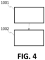
- FIG. 4 shows a flow diagram of a preferred embodiment of a method according to the second aspect of the invention, and said embodiment comprises the following:
- a preferred embodiment of the aforementioned method is implemented using the system of FIG. 2 .
- Another embodiment of the method is implemented by operating the system of FIG. 3 .
- An operation of the system of FIG. 3 for implementing an embodiment of the method according to the invention is as follows.
- Wetted textile and denim product B (shown in FIG. 2 ) to be bleached, said product B exhibiting a substantially high humidity, and for example has a wet pickup value in the range of 20-150%, is placed in the ozone reaction machine 3 which, as mentioned further above, can also be called textile processing machine.
- ozone gas is supplied to the ozone reaction machine 3 via the latter's gas line 19 entrance. While the ozone gas is being supplied, the high humidity of the gaseous atmosphere with the ozone inside the machine 3 is reduced by the dehumidification unit 6 inside which there accumulates liquid water from the dew formed.
- the dehumidified air (gaseous mixture) is given back to the ozone reaction machine 3 via the low humidity gas return 21 after dehumidification. This way it is achieved that dew and dripping do not occur inside the ozone reaction machine 3. Over time, the relative humidity inside the ozone reaction machine 3 does not rise above 100%.
- the textile and denim product to be bleached B in the ozone reaction machine 3 is bleached homogeneously, and staining does not occur. Thus, the desired bleached and homogeneous appearance textile and denim product E (shown in FIG. 2 ) emerges.
- the product B is introduced in the machine 3 together with another wet material e.g. together with wet cloths or towels.
- the product B being wet or dry is introduced in the machine 3 wherein water is also provided in a liquid, vapor (gas) or spray form.
- the system 30 of FIG. 3 can perform a bleaching process of textile and denim products by using ozone and water. Further aspects of the operation of the system 30 of FIG. 3 are as follows.
- the system's PSA oxygen concentrator 1 purifies the oxygen in the air coming from the compressed dry air inlet 17 and sends it to the ozone generator 2 via the oxygen gas line 18.
- the ozone generator 2 produces ozone from oxygen. During the ozone production, the ozone generator 2 needs to be cooled.
- the ozone generator water cooler 12 provides the cooling process.
- Said ozone generator water cooler 12 is a closed-circuit water-cooling system. Cooling is provided by circulating the cold water produced in the ozone generator water cooler 12 through the ozone generator 2 via the ozone generator cold water inlet line 23. The generated heated water is returned to the ozone generator water cooler 12 via the ozone generator heated water outlet line 24. The ozone gas produced in the ozone generator 2 is sent to the ozone reaction machine 3 via the ozone gas line 19. In the ozone reaction machine 3, indigo and reactive dyestuffs on high humidity and wet textiles and denim products may react chemically with ozone gas which, hence, bleaches the textiles by making the latter's colors.
- the gas at the high humidity gas outlet 20 from the interior of the ozone reaction machine 3 is first passed through a strainer filter 4, and then the temperature and humidity are measured by the machine outlet temperature and humidity measurement unit 5. Humidity is reduced in the gaseous mixture passing through dehumidification unit 6, as a result of the formation of dew. Hence, water droplets are formed as a result of dew accumulated in the dehumidification unit 6.
- the accumulated condensed water is discharged from the condensed water discharge outlet 16 through the two valves 14, 15 which are the condensed water upper discharge valve 14 and the condensed water lower discharge valve 15.
- the temperature and humidity of the air whose humidity is reduced in the dehumidification unit 6 are measured again in the dehumidification output 20 temperature and humidity measurement unit 7.
- the ozone (the gaseous mixture comprising the ozone) is returned to the ozone reaction machine 3 via the low humidity gas return 21 and the circulation pump 8.
- a low temperature is required in order to form dew in the dehumidifier 6.
- this low temperature is 2-3 degrees slightly above freezing point.
- a dehumidification cooler 13 is used to maintain this temperature.
- Said dehumidification cooler 13 is a closed-circuit water cooler. The water that is cooled by the dehumidification cooler 13 is circulated in the dehumidification system through the dehumidification system cold water inlet line 25. The heated water is returned to the dehumidification cooler 13 via the dehumidification system heated water outlet line 26.
- the ozone gas coming from the ozone gas discharge outlet 22 of the machine is converted to oxygen by the ozone gas catalytic disruptor 9 and the degraded ozone gas (oxygen) is given to the environment as degraded ozone gas (oxygen) via the ozone gas discharge pump 10 and the discharge outlet 27.
- the control unit 11 HMI+ PLC
- the inventors propose the following for explaining why there are spots in textile and denims processed with machines known in the prior art.
- the textile and denim product B to be bleached B is put into the ozone reaction machine A.
- ozone gas is supplied from the ozone gas line 19 entrance of the ozone reaction machine 30.
- the relative humidity in the ozone reaction machine exceeds 100% over time, the dew and water droplets C occur.
- the water droplets C adhere to the textile and denim product to be bleached B, causing some places/spots to become more wet.
- the present invention may also be used for the processing of textiles dyed with different dyes, or not dyed at all.
- the method according to the present invention may also comprise one more additional steps to the ones described further above. Non-limiting examples of such additional steps are wetting, drying, dyeing, washing, abrading, bleaching, wetting the textiles or otherwise preparing, processing or finishing the textiles.
Landscapes
- Engineering & Computer Science (AREA)
- Textile Engineering (AREA)
- Health & Medical Sciences (AREA)
- Toxicology (AREA)
- Treatment Of Fiber Materials (AREA)
- Chemical Or Physical Treatment Of Fibers (AREA)
Claims (13)
- Système comprenant :une machine (3, 31) destinée au traitement de textiles et conçue pour traiter, à l'intérieur de celle-ci, des textiles avec un mélange gazeux comprenant de l'ozone gazeux ;un générateur d'ozone (2) conçu pour produire et fournir de l'ozone gazeux du mélange gazeux à la machine (3, 31) ;un système de déshumidification (6) relié à, ou intégré dans, la machine (3, 31) et conçu pour réduire une humidité du mélange gazeux à l'intérieur de la machine (3, 31) ; etune pompe de circulation (8) conçue pour prélever un mélange gazeux de la machine de traitement de textiles, pour faire passer ledit mélange gazeux à travers le système de déshumidification (6) pour diminuer l'humidité du mélange gazeux et pour renvoyer vers la machine de traitement de textiles (3, 31) le mélange gazeux dont l'humidité est réduite par le système de déshumidification (6) pendant un fonctionnement du système.
- Système selon la revendication 1, dans lequel le système de déshumidification (6) comprend l'un quelconque parmi un compresseur déshumidificateur, un condenseur, un déshumidificateur à dessiccant, un déshumidificateur à membrane, ou une combinaison de ceux-ci.
- Système selon l'une quelconque des revendications précédentes, dans lequel la machine (3, 31) comprend une chambre (33) et un tambour (32) dans la chambre (33), le tambour (32) étant conçu pour recevoir les textiles à traiter.
- Système selon l'une quelconque des revendications précédentes, dans lequel le système de déshumidification comprend un refroidisseur à circuit fermé (13) conçu pour refroidir une zone par l'intermédiaire de laquelle le mélange gazeux passe dans le système de déshumidification, de telle sorte que de la rosée est produite dans ladite zone.
- Système selon l'une quelconque des revendications précédentes, dans lequel le système de déshumidification (6) comprend un condenseur et une conduite d'évacuation d'eau qui comprend une sortie d'évacuation (16) et un système anti-fuite de gaz conçu pour évacuer par l'intermédiaire de celui-ci l'eau formée par la rosée formée au niveau du condenseur lorsque le système est en fonctionnement, et le système anti-fuite de gaz est également conçu pour empêcher de l'ozone de s'échapper vers l'environnement par l'intermédiaire de la conduite d'évacuation d'eau lorsque le système est en fonctionnement, de préférence, le système anti-fuite de gaz comprend un siphon et/ou deux vannes d'évacuation d'eau (14, 15) qui sont situées séquentiellement le long de la conduite d'évacuation d'eau.
- Système selon l'une quelconque des revendications précédentes, comprenant en outre un filtre (4) par l'intermédiaire duquel le système de déshumidification (6) est relié à la machine de traitement de textiles (3, 31) de telle sorte que la machine de traitement de textiles est conçue pour recevoir le mélange gazeux par l'intermédiaire dudit filtre (4), dans lequel le filtre (4) est conçu pour filtrer le mélange gazeux, de préférence le filtre étant un filtre à crépine.
- Système selon l'une quelconque des revendications précédentes, comprenant en outre une ou plusieurs unités de mesure (5, 7) conçues pour mesurer la température et/ou l'humidité du mélange gazeux.
- Système selon l'une quelconque des revendications précédentes, comprenant en outre une unité de commande programmable (11) et une interface reliée à l'unité de commande (11), cette dernière étant conçue pour commander la machine (3, 31) et/ou le système de déshumidification (6), de préférence, l'unité de commande programmable étant basée sur un PLC.
- Système selon les revendications 8 et 7, dans lequel l'unité de commande programmable (11) est reliée fonctionnellement à la une ou plusieurs unités de mesure (5, 7) et conçue pour traiter les mesures effectuées par la une ou plusieurs unités de mesure (5, 7) pendant un fonctionnement du système.
- Procédé de traitement de textiles, comprenant :
dans une machine (3, 31) de traitement de textiles d'un système selon l'une quelconque des revendications précédentes, le traitement de textiles avec un mélange gazeux comprenant de l'ozone gazeux ; et, en utilisant un système de déshumidification (6) relié à, ou intégré dans, la machine (3, 31) pour réduire une humidité du mélange gazeux. - Procédé selon la revendication 10, dans lequel les textiles sont des vêtements, de préférence des vêtements teints, ou des jeans, ou des tricots, ou des vêtements comprenant de la toile de jean ou de la laine.
- Procédé selon les revendications 10 ou 11, dans lequel le système de déshumidification (6) réduit l'humidité relative d'une atmosphère gazeuse à l'intérieur de la machine (3, 31) de telle sorte qu'une condensation de l'humidité dans la machine de traitement de textiles (3, 31) est réduite ou empêchée.
- Procédé selon l'une quelconque des revendications 10 à 12, comprenant en outre une ou plusieurs étapes supplémentaires de traitement de textiles.
Applications Claiming Priority (1)
| Application Number | Priority Date | Filing Date | Title |
|---|---|---|---|
| TR202200633 | 2022-01-19 |
Publications (4)
| Publication Number | Publication Date |
|---|---|
| EP4215664A2 EP4215664A2 (fr) | 2023-07-26 |
| EP4215664A3 EP4215664A3 (fr) | 2023-08-02 |
| EP4215664C0 EP4215664C0 (fr) | 2024-11-06 |
| EP4215664B1 true EP4215664B1 (fr) | 2024-11-06 |
Family
ID=86852291
Family Applications (1)
| Application Number | Title | Priority Date | Filing Date |
|---|---|---|---|
| EP22383272.6A Active EP4215664B1 (fr) | 2022-01-19 | 2022-12-23 | Système et procédé de traitement de textiles |
Country Status (2)
| Country | Link |
|---|---|
| EP (1) | EP4215664B1 (fr) |
| ES (1) | ES2999156T3 (fr) |
Family Cites Families (4)
| Publication number | Priority date | Publication date | Assignee | Title |
|---|---|---|---|---|
| US6506309B1 (en) * | 2000-11-16 | 2003-01-14 | Awois, Llc | Ozone dissolving system for a reservoir |
| ATE366837T1 (de) * | 2002-05-17 | 2007-08-15 | Howa Kabushiki Kaisha | Textilgutentfärbungsvorrichtung und -verfahren |
| US10227720B2 (en) * | 2014-04-24 | 2019-03-12 | Guardian Manufacturing, Inc. | Ozone process for color removal |
| ES2873827T3 (es) | 2018-12-21 | 2021-11-04 | Jeanologia Sl | Un método para procesar prendas de lana para inhibir su posterior fieltrado y encogimiento |
-
2022
- 2022-12-23 ES ES22383272T patent/ES2999156T3/es active Active
- 2022-12-23 EP EP22383272.6A patent/EP4215664B1/fr active Active
Also Published As
| Publication number | Publication date |
|---|---|
| ES2999156T3 (en) | 2025-02-24 |
| EP4215664A2 (fr) | 2023-07-26 |
| EP4215664C0 (fr) | 2024-11-06 |
| EP4215664A3 (fr) | 2023-08-02 |
Similar Documents
| Publication | Publication Date | Title |
|---|---|---|
| KR100647251B1 (ko) | 섬유 제품의 탈색 가공 장치 및 탈색 가공 방법 | |
| US5313811A (en) | Apparatus for treatment of dyed garments and fabrics with oxidizing gases | |
| US10227720B2 (en) | Ozone process for color removal | |
| KR101318080B1 (ko) | 인디고 염색을 위한 장치 및 방법 | |
| CN106661793B (zh) | 用于漂白纺织品的方法和系统 | |
| TWI399470B (zh) | 用於紡織基布染色的方法和設備 | |
| CN101415874A (zh) | 漂白纤维品的制备方法以及其使用的装置和由其得到的漂白纤维品 | |
| KR19990064282A (ko) | 초임계 유체로 직물 기층을 처리하는 방법 및 장치 | |
| US20110083282A1 (en) | Ozone process for denim | |
| CA1143513A (fr) | Methode de traitement d'articles textiles dans des appareils de teinture au jet | |
| US20230228031A1 (en) | System and a method for processing textiles | |
| US20190234011A1 (en) | Ozone process for color removal and drain system | |
| EP4215664A2 (fr) | Système et procédé de traitement de textiles | |
| EP1264026B1 (fr) | Appareil destine au traitement de vetements teints et de matieres textiles par des gaz oxydants | |
| WO2008056396A1 (fr) | Appareil de traitement de marchandises en morceaux | |
| WO2017066000A1 (fr) | Élimination de couleur de l'eau avec de l'ozone dans un procédé de blanchiment de textiles | |
| KR101918154B1 (ko) | 오존을 이용한 의류 제품 탈색 장치 및 방법 | |
| WO2020181242A1 (fr) | Procédé à l'ozone pour système d'élimination de couleur et de drain | |
| US4931064A (en) | Method and apparatus for discontinuous wet processing of knitted or worked textile material | |
| KR100717106B1 (ko) | 로프형 직물 세척 방법 및 장치 | |
| EP3670737B1 (fr) | Procédé de traitement de vêtements en laine pour inhiber leur feutrage et leur rétrécissement ultérieurs | |
| SU1594229A1 (ru) | Устройство дл крашени текстильного материала | |
| JP4022449B2 (ja) | 模様柄形成方法 | |
| TR2025016058A2 (tr) | Veri̇mli̇li̇ği̇ arttirilmiş bi̇r i̇ndi̇go boyama yöntemi̇ ve maki̇nesi̇ | |
| HK1074065B (en) | Textile product decoloring device and decoloring method |
Legal Events
| Date | Code | Title | Description |
|---|---|---|---|
| PUAI | Public reference made under article 153(3) epc to a published international application that has entered the european phase |
Free format text: ORIGINAL CODE: 0009012 |
|
| STAA | Information on the status of an ep patent application or granted ep patent |
Free format text: STATUS: THE APPLICATION HAS BEEN PUBLISHED |
|
| PUAL | Search report despatched |
Free format text: ORIGINAL CODE: 0009013 |
|
| AK | Designated contracting states |
Kind code of ref document: A2 Designated state(s): AL AT BE BG CH CY CZ DE DK EE ES FI FR GB GR HR HU IE IS IT LI LT LU LV MC ME MK MT NL NO PL PT RO RS SE SI SK SM TR |
|
| AK | Designated contracting states |
Kind code of ref document: A3 Designated state(s): AL AT BE BG CH CY CZ DE DK EE ES FI FR GB GR HR HU IE IS IT LI LT LU LV MC ME MK MT NL NO PL PT RO RS SE SI SK SM TR |
|
| RIC1 | Information provided on ipc code assigned before grant |
Ipc: D06M 11/34 20060101ALI20230623BHEP Ipc: D06L 4/50 20170101ALI20230623BHEP Ipc: D06B 9/00 20060101AFI20230623BHEP |
|
| STAA | Information on the status of an ep patent application or granted ep patent |
Free format text: STATUS: REQUEST FOR EXAMINATION WAS MADE |
|
| 17P | Request for examination filed |
Effective date: 20240118 |
|
| RAV | Requested validation state of the european patent: fee paid |
Extension state: TN Effective date: 20240118 |
|
| RBV | Designated contracting states (corrected) |
Designated state(s): AL AT BE BG CH CY CZ DE DK EE ES FI FR GB GR HR HU IE IS IT LI LT LU LV MC ME MK MT NL NO PL PT RO RS SE SI SK SM TR |
|
| GRAJ | Information related to disapproval of communication of intention to grant by the applicant or resumption of examination proceedings by the epo deleted |
Free format text: ORIGINAL CODE: EPIDOSDIGR1 |
|
| STAA | Information on the status of an ep patent application or granted ep patent |
Free format text: STATUS: GRANT OF PATENT IS INTENDED |
|
| GRAP | Despatch of communication of intention to grant a patent |
Free format text: ORIGINAL CODE: EPIDOSNIGR1 |
|
| INTG | Intention to grant announced |
Effective date: 20240605 |
|
| GRAS | Grant fee paid |
Free format text: ORIGINAL CODE: EPIDOSNIGR3 |
|
| GRAA | (expected) grant |
Free format text: ORIGINAL CODE: 0009210 |
|
| STAA | Information on the status of an ep patent application or granted ep patent |
Free format text: STATUS: THE PATENT HAS BEEN GRANTED |
|
| AK | Designated contracting states |
Kind code of ref document: B1 Designated state(s): AL AT BE BG CH CY CZ DE DK EE ES FI FR GB GR HR HU IE IS IT LI LT LU LV MC ME MK MT NL NO PL PT RO RS SE SI SK SM TR |
|
| REG | Reference to a national code |
Ref country code: GB Ref legal event code: FG4D Ref country code: TN Ref legal event code: VAGR Ref document number: TN/P/2024/000361 Country of ref document: TN |
|
| REG | Reference to a national code |
Ref country code: CH Ref legal event code: EP |
|
| REG | Reference to a national code |
Ref country code: DE Ref legal event code: R096 Ref document number: 602022007501 Country of ref document: DE |
|
| REG | Reference to a national code |
Ref country code: IE Ref legal event code: FG4D |
|
| U01 | Request for unitary effect filed |
Effective date: 20241106 |
|
| U07 | Unitary effect registered |
Designated state(s): AT BE BG DE DK EE FI FR IT LT LU LV MT NL PT RO SE SI Effective date: 20241113 |
|
| U20 | Renewal fee for the european patent with unitary effect paid |
Year of fee payment: 3 Effective date: 20241227 |
|
| REG | Reference to a national code |
Ref country code: ES Ref legal event code: FG2A Ref document number: 2999156 Country of ref document: ES Kind code of ref document: T3 Effective date: 20250224 |
|
| PG25 | Lapsed in a contracting state [announced via postgrant information from national office to epo] |
Ref country code: IS Free format text: LAPSE BECAUSE OF FAILURE TO SUBMIT A TRANSLATION OF THE DESCRIPTION OR TO PAY THE FEE WITHIN THE PRESCRIBED TIME-LIMIT Effective date: 20250306 Ref country code: HR Free format text: LAPSE BECAUSE OF FAILURE TO SUBMIT A TRANSLATION OF THE DESCRIPTION OR TO PAY THE FEE WITHIN THE PRESCRIBED TIME-LIMIT Effective date: 20241106 |
|
| PG25 | Lapsed in a contracting state [announced via postgrant information from national office to epo] |
Ref country code: NO Free format text: LAPSE BECAUSE OF FAILURE TO SUBMIT A TRANSLATION OF THE DESCRIPTION OR TO PAY THE FEE WITHIN THE PRESCRIBED TIME-LIMIT Effective date: 20250206 |
|
| PG25 | Lapsed in a contracting state [announced via postgrant information from national office to epo] |
Ref country code: GR Free format text: LAPSE BECAUSE OF FAILURE TO SUBMIT A TRANSLATION OF THE DESCRIPTION OR TO PAY THE FEE WITHIN THE PRESCRIBED TIME-LIMIT Effective date: 20250207 |
|
| PG25 | Lapsed in a contracting state [announced via postgrant information from national office to epo] |
Ref country code: PL Free format text: LAPSE BECAUSE OF FAILURE TO SUBMIT A TRANSLATION OF THE DESCRIPTION OR TO PAY THE FEE WITHIN THE PRESCRIBED TIME-LIMIT Effective date: 20241106 |
|
| PG25 | Lapsed in a contracting state [announced via postgrant information from national office to epo] |
Ref country code: RS Free format text: LAPSE BECAUSE OF FAILURE TO SUBMIT A TRANSLATION OF THE DESCRIPTION OR TO PAY THE FEE WITHIN THE PRESCRIBED TIME-LIMIT Effective date: 20250206 |
|
| PG25 | Lapsed in a contracting state [announced via postgrant information from national office to epo] |
Ref country code: SM Free format text: LAPSE BECAUSE OF FAILURE TO SUBMIT A TRANSLATION OF THE DESCRIPTION OR TO PAY THE FEE WITHIN THE PRESCRIBED TIME-LIMIT Effective date: 20241106 |
|
| PG25 | Lapsed in a contracting state [announced via postgrant information from national office to epo] |
Ref country code: SK Free format text: LAPSE BECAUSE OF FAILURE TO SUBMIT A TRANSLATION OF THE DESCRIPTION OR TO PAY THE FEE WITHIN THE PRESCRIBED TIME-LIMIT Effective date: 20241106 |
|
| PG25 | Lapsed in a contracting state [announced via postgrant information from national office to epo] |
Ref country code: CZ Free format text: LAPSE BECAUSE OF FAILURE TO SUBMIT A TRANSLATION OF THE DESCRIPTION OR TO PAY THE FEE WITHIN THE PRESCRIBED TIME-LIMIT Effective date: 20241106 |
|
| PLBE | No opposition filed within time limit |
Free format text: ORIGINAL CODE: 0009261 |
|
| STAA | Information on the status of an ep patent application or granted ep patent |
Free format text: STATUS: NO OPPOSITION FILED WITHIN TIME LIMIT |
|
| PG25 | Lapsed in a contracting state [announced via postgrant information from national office to epo] |
Ref country code: MC Free format text: LAPSE BECAUSE OF FAILURE TO SUBMIT A TRANSLATION OF THE DESCRIPTION OR TO PAY THE FEE WITHIN THE PRESCRIBED TIME-LIMIT Effective date: 20241106 |
|
| 26N | No opposition filed |
Effective date: 20250807 |
|
| PG25 | Lapsed in a contracting state [announced via postgrant information from national office to epo] |
Ref country code: IE Free format text: LAPSE BECAUSE OF NON-PAYMENT OF DUE FEES Effective date: 20241223 |
|
| PGFP | Annual fee paid to national office [announced via postgrant information from national office to epo] |
Ref country code: TR Payment date: 20251216 Year of fee payment: 4 |
|
| U20 | Renewal fee for the european patent with unitary effect paid |
Year of fee payment: 4 Effective date: 20251229 |
|
| PGFP | Annual fee paid to national office [announced via postgrant information from national office to epo] |
Ref country code: ES Payment date: 20260112 Year of fee payment: 4 |
|
| PG25 | Lapsed in a contracting state [announced via postgrant information from national office to epo] |
Ref country code: CY Free format text: LAPSE BECAUSE OF FAILURE TO SUBMIT A TRANSLATION OF THE DESCRIPTION OR TO PAY THE FEE WITHIN THE PRESCRIBED TIME-LIMIT Effective date: 20241106 |