EP4215767B1 - Klappmechanismus und endgerätevorrichtung - Google Patents
Klappmechanismus und endgerätevorrichtung Download PDFInfo
- Publication number
- EP4215767B1 EP4215767B1 EP22844419.6A EP22844419A EP4215767B1 EP 4215767 B1 EP4215767 B1 EP 4215767B1 EP 22844419 A EP22844419 A EP 22844419A EP 4215767 B1 EP4215767 B1 EP 4215767B1
- Authority
- EP
- European Patent Office
- Prior art keywords
- swing arm
- fixing plate
- rotating
- support body
- folding mechanism
- Prior art date
- Legal status (The legal status is an assumption and is not a legal conclusion. Google has not performed a legal analysis and makes no representation as to the accuracy of the status listed.)
- Active
Links
Images






Classifications
-
- F—MECHANICAL ENGINEERING; LIGHTING; HEATING; WEAPONS; BLASTING
- F16—ENGINEERING ELEMENTS AND UNITS; GENERAL MEASURES FOR PRODUCING AND MAINTAINING EFFECTIVE FUNCTIONING OF MACHINES OR INSTALLATIONS; THERMAL INSULATION IN GENERAL
- F16C—SHAFTS; FLEXIBLE SHAFTS; ELEMENTS OR CRANKSHAFT MECHANISMS; ROTARY BODIES OTHER THAN GEARING ELEMENTS; BEARINGS
- F16C11/00—Pivots; Pivotal connections
- F16C11/04—Pivotal connections
-
- H—ELECTRICITY
- H04—ELECTRIC COMMUNICATION TECHNIQUE
- H04M—TELEPHONIC COMMUNICATION
- H04M1/00—Substation equipment, e.g. for use by subscribers
- H04M1/02—Constructional features of telephone sets
- H04M1/0202—Portable telephone sets, e.g. cordless phones, mobile phones or bar type handsets
- H04M1/0206—Portable telephones comprising a plurality of mechanically joined movable body parts, e.g. hinged housings
- H04M1/0208—Portable telephones comprising a plurality of mechanically joined movable body parts, e.g. hinged housings characterized by the relative motions of the body parts
- H04M1/0214—Foldable telephones, i.e. with body parts pivoting to an open position around an axis parallel to the plane they define in closed position
- H04M1/0216—Foldable in one direction, i.e. using a one degree of freedom hinge
- H04M1/022—The hinge comprising two parallel pivoting axes
-
- G—PHYSICS
- G06—COMPUTING OR CALCULATING; COUNTING
- G06F—ELECTRIC DIGITAL DATA PROCESSING
- G06F1/00—Details not covered by groups G06F3/00 - G06F13/00 and G06F21/00
- G06F1/16—Constructional details or arrangements
- G06F1/1613—Constructional details or arrangements for portable computers
- G06F1/1633—Constructional details or arrangements of portable computers not specific to the type of enclosures covered by groups G06F1/1615 - G06F1/1626
- G06F1/1675—Miscellaneous details related to the relative movement between the different enclosures or enclosure parts
- G06F1/1681—Details related solely to hinges
-
- G—PHYSICS
- G06—COMPUTING OR CALCULATING; COUNTING
- G06F—ELECTRIC DIGITAL DATA PROCESSING
- G06F1/00—Details not covered by groups G06F3/00 - G06F13/00 and G06F21/00
- G06F1/16—Constructional details or arrangements
- G06F1/1613—Constructional details or arrangements for portable computers
- G06F1/1633—Constructional details or arrangements of portable computers not specific to the type of enclosures covered by groups G06F1/1615 - G06F1/1626
- G06F1/1637—Details related to the display arrangement, including those related to the mounting of the display in the housing
- G06F1/1652—Details related to the display arrangement, including those related to the mounting of the display in the housing the display being flexible, e.g. mimicking a sheet of paper, or rollable
-
- H—ELECTRICITY
- H04—ELECTRIC COMMUNICATION TECHNIQUE
- H04M—TELEPHONIC COMMUNICATION
- H04M1/00—Substation equipment, e.g. for use by subscribers
- H04M1/02—Constructional features of telephone sets
- H04M1/0202—Portable telephone sets, e.g. cordless phones, mobile phones or bar type handsets
- H04M1/0206—Portable telephones comprising a plurality of mechanically joined movable body parts, e.g. hinged housings
- H04M1/0208—Portable telephones comprising a plurality of mechanically joined movable body parts, e.g. hinged housings characterized by the relative motions of the body parts
- H04M1/0214—Foldable telephones, i.e. with body parts pivoting to an open position around an axis parallel to the plane they define in closed position
-
- H—ELECTRICITY
- H04—ELECTRIC COMMUNICATION TECHNIQUE
- H04M—TELEPHONIC COMMUNICATION
- H04M1/00—Substation equipment, e.g. for use by subscribers
- H04M1/02—Constructional features of telephone sets
- H04M1/0202—Portable telephone sets, e.g. cordless phones, mobile phones or bar type handsets
- H04M1/026—Details of the structure or mounting of specific components
- H04M1/0266—Details of the structure or mounting of specific components for a display module assembly
- H04M1/0268—Details of the structure or mounting of specific components for a display module assembly including a flexible display panel
Definitions
- This application relates to the field of terminal technologies, and in particular, to a folding mechanism and a terminal device.
- the CN112901649A relates to a three-section type inner folding hinge. It is described that the three-section type inner folding hinge comprises a left spring support, a right spring support, a synchronizing mechanism, a locking mechanism and a screen supporting and avoiding mechanism; the synchronizing mechanism comprises a baffle, a torsion piece, a gear set and a limiting plate; the screen supporting and avoiding mechanism comprises a first rotating block, a second rotating block, a sliding block, a lifting block, a left cover plate and a right cover plate; one end of the left spring support is connected to the gear set and the first rotating block, and one end of the right spring support is connected to the gear set and the second rotating block; the first rotating block and the second rotating block partially abut against the lifting block to achieve the lifting action of the lifting block; extending columns are arranged at the two ends of the lifting block; inclined grooves are formed in the ends of the left cover plate and the right cover plate; and the extending columns are correspondingly installed in the inclined grooves respectively
- CN213270695U describes a movement mechanism applied to an infolding flexible screen terminal, which comprises a middle supporting structure, a left side supporting structure, a right side supporting structure, a left side movable supporting plate and a right side movable supporting plate. It is described that the left and right movable supporting plates are rotationally connected with the left and right supporting structures outside the middle supporting structure respectively; rotation of the left movable supporting plate and the right movable supporting plate can be directly planned through the relation between the gear and the rack, the reference circle diameter of the gear can be increased in a limited space through the virtual circle center design, and therefore the rack is driven to generate a larger sliding distance under the condition of small rotation angle.
- the foldable mobile phone includes a housing, a folding mechanism, and a flexible display.
- the folding mechanism includes a rotating arm, a lifting door plate, and a spring.
- an upper surface of the lifting door plate is kept flush with an upper surface of the rotating arm under an action of the rotating arm, so that the lifting door plate and the rotating arm may jointly support the flexible display.
- the rotating arm compresses the spring, and the spring drives the lifting door plate fastened thereto to descend, so as to avoid a rounded corner generated when the flexible display is folded.
- the spring and the rotating arm are mainly used to lower the lifting door plate.
- the spring when the spring is compressed to a maximum compression amount, a specific space needs to be occupied, and an axial direction of the spring is the same as a thickness direction of the foldable mobile phone. Consequently, the folding mechanism occupies large space in the thickness direction of the foldable mobile phone.
- this application provides a folding mechanism and a terminal device, which can reduce space occupied by the folding mechanism in a thickness direction of a foldable mobile phone.
- Appended claim 1 defines a folding mechanism for a foldable mobile phone.
- Appended claim 13 defines a terminal device. The invention and its scope of protection is defined by these claims.
- This application provides a folding mechanism, including a base; a support body, where the support body is connected to the base, the support body may move toward or away from the base, and the support body is provided with a first groove and a second groove that are corresponding to each other in position; a first swing arm, where the first swing arm includes a first rotating portion and a first rotating body fastened to the first rotating portion, the first rotating portion is rotatably connected to the base, a part of the first rotating body extends into the first groove, and the first rotating body is configured to provide a force for the support body in a rotation process, so that the support body moves toward or away from the base; and a second swing arm, where the second swing arm includes a second rotating portion and a second rotating body fastened to the second rotating portion, the second rotating portion is rotatably connected to the base, a part of the second rotating body extends into the second groove, and the second rotating body is configured to provide a force for the support body in a rotation process, so that the support body moves toward or away from
- the first swing arm and the second swing arm may be folded or unfolded.
- the first swing arm and the second swing arm can provide a force for the support body, so that the support body moves away from the base, that is, the support body can rise.
- the support body can provide support for a flexible display jointly with the first swing arm and the second swing arm.
- the first swing arm and the second swing arm can provide a force for the support body, so that the support body moves toward the base, that is, the support body can descend, so as to avoid a rounded corner generated when the flexible display is bent.
- the folding mechanism in this application does not need to use a spring, and therefore, space required by the spring when the spring is compressed to a limit does not need to be reserved. That is, in this embodiment of this application, space in a thickness direction of the folding mechanism can be reduced, and a thickness of the terminal device is further reduced.
- the first rotating body may provide the support body with a limit in a thickness direction of the terminal device, thereby limiting a displacement of the support body in the thickness direction, and reducing damage to the flexible display or another component of the terminal device caused by a large displacement of the support body.
- the support body includes a first fixing plate and a second fixing plate that are disposed opposite to each other, and a third fixing plate connected between the first fixing plate and the second fixing plate, and the third fixing plate separates space between the first fixing plate and the second fixing plate into the first groove and the second groove.
- the support body may be formed through integral molding or welded with the first fixing plate, the second fixing plate, and the third fixing plate. A structure of the support body is relatively simple.
- the second fixing plate is closer to the base than the first fixing plate, the second fixing plate is closer to the base than the first fixing plate, a size of the second fixing plate in a first direction is greater than a size of the first fixing plate in the first direction, and the first direction is a direction of an arrangement direction of the first swing arm and the second swing arm.
- the first fixing plate can provide enough space for rotation of the first rotating body, so as to prevent interference of the first fixing plate and the first swing arm.
- the first fixing plate has a first surface facing the second fixing plate; and the first rotating body includes a first pressure surface, and when the first swing arm and the second swing arm are in a flattened state, the first pressure surface abuts against the first surface. In this way, in a process of unfolding the first swing arm and the second swing arm, and when the first swing arm and the second swing arm are in a flattened state, the first pressure surface can always provide a force for the first surface.
- the second fixing plate has a second surface facing the first fixing plate; and the first rotating body further includes a second pressure surface connected to the first pressure surface, and in a process of folding the first swing arm and the second swing arm, the second pressure surface interacts with the second surface. In this way, in a process of folding the first swing arm and the second swing arm, the second pressure surface can provide a force for the second surface, so that the support body moves toward the base.
- the first pressure surface includes a first plane.
- the first pressure surface In a process of unfolding the first swing arm and the second swing arm, and when the first swing arm and the second swing arm are in a flattened state, the first pressure surface needs to continuously provide a force for the first surface, and when the first pressure surface includes a plane, the plane may provide a force for the first surface, so that the first rotating body can provide relatively stable support for the support body.
- the second pressure surface includes a second plane, the second plane is connected to the first pressure surface, and when the first swing arm and the second swing arm are in a folded state, the second plane abuts against the second surface. In this way, when the first swing arm and the second swing arm are in a folded state, the second plane may provide a force for the second surface, so that the first rotating body can provide relatively stable support for the support body.
- the second pressure surface further includes a third plane connected to the first arc surface, and the third plane is further configured to: when the first swing arm and the second swing arm are in a flattened state, a part of the third plane abuts against the second surface. In this way, the third plane can provide stable support for the support body.
- the first pressure surface and the second pressure surface are connected to form a second arc surface, and in a process of folding the first swing arm and the second swing arm, the second arc surface interacts with the second surface; and in a process of unfolding the first swing arm and the second swing arm, the second arc surface interacts with the first surface.
- the second arc surface in a process of unfolding the first swing arm and the second swing arm, the second arc surface always interacts with the first surface; and in a process of folding the first swing arm and the second swing arm, the second arc surface also always interacts with the second surface.
- the arc surface has a characteristic of smooth surface. Therefore, the support body can move more smoothly.
- the first rotating body includes a connector and a fastener fastened to the connector, at least a part of the fastener extends into the first groove, and the fastener is configured to provide, in a rotation process, a force for the support body to move toward or away from the base.
- the fastener can always provide a force for the support body, so that the support body moves away from or toward the base.
- the connector is located on a side surface of the support body, the fastener is disposed toward the side surface, and the side surface is a surface adjacent to a side on which the first swing arm is located.
- the fastener may extend from the side surface into the first groove.
- a first incision is disposed on a first side surface of the first rotating portion, a part of the first rotating body extends into the first incision, and the first side surface is a surface that is of the first rotating portion and that is opposite to the second rotating portion when the first swing arm and the second swing arm are in a flattened state.
- a lateral size of the first swing arm can be reduced. Because a lateral direction of the first swing arm is the same as a width direction of the terminal device, a size of a folding assembly along the width direction of the terminal device can be further reduced.
- a size of the first rotating body in the width direction of the terminal device may be increased, so as to improve strength of the first rotating body.
- the first incision has two opposite side walls, and the first rotating body is fastened to the two side walls.
- a fastening structure of the first rotating body on the first rotating portion is relatively simple.
- the first fixing plate includes a fastening body and a convex portion fastened to a side of the fastening body, and a part of the convex portion extends into the first incision.
- a size of the support body in the width direction of the terminal device can be further increased, and a size of the entire folding mechanism in the width direction of the terminal device can be reduced.
- the support body is provided with the first groove and the second groove, the foregoing structure may improve strength of the support body to a specific extent, and alleviate the following case:
- a third connecting plate between the first groove and the second groove is relatively small because a size of the support body along the width direction of the terminal device is relatively small, which causes a crack of the support body when the support body is stressed.
- a first through hole is disposed on a second side surface of the first rotating portion, the second side surface is adjacent to the first side surface, and the first incision is connected to the first through hole; and the first rotating body further has a connection surface facing the first through hole, and a projection of the connection surface on the side wall is in contact with or has a clearance with an edge of a projection of the first through hole on the side wall.
- the folding mechanism further includes a first rotating shaft, the first rotating shaft is rotatably connected to the base, and the first swing arm is fastened to the first rotating shaft.
- the first swing arm may be first fabricated, and then the first swing arm and the first rotating shaft are assembled.
- the projection of the connection surface on the side wall is in contact with or has a clearance with an edge of a projection of the first through hole on the side wall, so that assembly is relatively convenient.
- a size of the first rotating body along the width direction of the terminal device can be further increased, so that strength of the first rotating body can be improved.
- first rotating bodies there are a plurality of the first rotating bodies, there are a plurality of the first grooves, and at least two first rotating bodies are in a one-to-one correspondence with two first grooves; and/or, there are a plurality of the second rotating bodies, there are a plurality of the second grooves, and at least two second rotating bodies are in a one-to-one correspondence with two second grooves.
- a plurality of the first rotating bodies can provide a more stable force for the support body, so that movement of the support body is more stable.
- a plurality of the second rotating bodies can also provide a more stable force for the support body, so that movement of the support body is more stable.
- the folding mechanism further includes a third swing arm, the third swing arm is connected to the base in a manner that the third swing arm can slide along the arc surface, the third swing arm and the first swing arm are arranged in a second direction, and the third swing arm is connected to the first swing arm, so that the third swing arm moves relative to the base in a manner synchronous with the first swing arm; and/or the folding mechanism further includes a fourth swing arm, and the fourth swing arm is connected to the base in a manner that the third swing arm can slide along the arc surface, the fourth swing arm and the second swing arm are arranged in the second direction, and the fourth swing arm is connected to the second swing arm, so that the fourth swing arm moves relative to the base in a manner synchronous with the first swing arm.
- the second direction is perpendicular to a movement direction of the support body and the first direction.
- the first swing arm and the third swing arm, and the second swing arm and the fourth swing arm can jointly provide support for the flexible display, thereby increasing a support area of the folding mechanism to the flexible display, and further improving support strength to the flexible display.
- the first swing arm and the third swing arm always keep moving synchronously
- the second swing arm and the fourth swing arm always keep moving synchronously. Therefore, in a process of folding or unfolding the terminal device, the flexible display can always keep a relatively high flatness, thereby increasing a service life of the flexible display.
- a first chute is disposed on a surface that is of the third swing arm and that faces the first swing arm.
- the first swing arm further includes a third rotating portion fastened to the first rotating portion and a first coupling shaft rotatably connected to the third rotating portion, and a part of the first coupling shaft extends into the first chute.
- the third rotating portion can drive the third swing arm by using the first coupling shaft, so that the third swing arm always rotates with the first swing arm synchronously.
- a second chute is disposed on a surface that is of the fourth swing arm and that faces the second swing arm.
- the second swing arm further includes a fourth rotating portion fastened to the second rotating portion and a second coupling shaft rotatably connected to the fourth rotating portion, and a part of the second coupling shaft extends into the second chute.
- the second swing arm may be connected to the base by using a second rotating shaft (another rotating shaft parallel to the first rotating shaft).
- the fourth rotating portion can drive the fourth swing arm by using the second coupling shaft, so that the fourth swing arm always rotates with the second swing arm synchronously.
- the first swing arm and the second swing arm are symmetrical about a center plane of the support body, and the center plane is a plane that is located in a geometric center of the support body and that is perpendicular to the first direction. In this way, support points provided by the first swing arm and the second swing arm to the support body are corresponding, thereby further improving motion stability of the support body.
- This application provides a terminal device, including the folding mechanism according to any one of the foregoing implementations.
- the terminal device can achieve all effects of the foregoing folding mechanism.
- a and/or B may indicate the following three cases: Only A exists, both A and B exist, and only B exists.
- first, second, and the like in the specification and claims of embodiments of this application are used to distinguish between different objects, and are not used to indicate a specific sequence of objects.
- a first target object, a second target object, and the like are used to distinguish between different target objects, and are not used to indicate a specific order of target objects.
- the word such as “as an example” or “for example” is used to represent giving an example, an illustration, or a description. Any embodiment or design scheme described as “as an example” or “for example” in embodiments of this application should not be explained as being preferred or having more advantages than another embodiment or design scheme. To be precise, the use of the word such as “as an example” or “for example” is intended to present a related concept in a specific manner.
- a plurality of means two or more.
- a plurality of processing units refer to two or more processing units
- a plurality of systems refer to two or more systems.
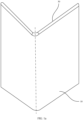
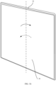
- a foldable mobile phone may be folded along a center of the foldable mobile phone.
- a folding angle of the foldable mobile phone is 0, a size of the foldable mobile phone may be reduced.
- a folding angle of the foldable mobile phone is 180°, and a flexible display 30 is in a state of a maximum display area, and in this case, a user may perform an operation on the flexible display 30.
- the folding angle refers to an included angle between left and right parts of the foldable mobile phone.
- three directions may be defined: a length direction E (a second direction) of the foldable mobile phone, a width direction F (a first direction) of the foldable mobile phone, and a thickness direction G of the foldable mobile phone.
- the foldable mobile phone includes a housing 10, a folding mechanism 20, and a flexible display 30 (not shown in FIG. 2 ).
- a through groove 11 is disposed on a side surface of the housing 10, and the folding mechanism 20 is connected to the through groove 11.
- the flexible display 30 is fastened to a side surface that is of the housing 10 and that is provided with the through groove 11.
- the folding mechanism 20 includes a base 21, two main swing arms 22, a synchronization mechanism 23, a support body 24, and two torsion swing arms 25.
- folding mechanism 20 there may be one, three, or more folding mechanisms 20.
- the folding mechanism 20 may be disposed in a middle of the base 21 along the length direction E.
- the plurality of folding mechanisms 20 may be distributed evenly along the length direction E.
- the base 21 includes a baseplate 211, a mounting base 212, a blocking portion 213, and a positioning position 214.
- the baseplate 211 is fastened to the through groove 11 of the housing 10.
- the baseplate 211 has an accommodating groove 2111, and a bottom wall 2113 of the accommodating groove 2111 is a plane.
- a baseplate clamping groove 2112 is disposed on one side that is of the mounting base 212 and that is away from the baseplate 211.
- Two opposite clamping groove side walls 2114 of the baseplate clamping groove 2112 are provided with one blocking portion 213, there is a clearance between the two blocking portions 213, and there is a clearance between a clamping groove bottom wall 2115 and the blocking portion 213.
- a surface that is of the blocking portion 213 and that faces the clamping groove bottom wall 2115 is a circular arc surface.
- the positioning position 214 is fastened to the bottom wall 2113 of the base 21, and a shape of a projection of the positioning position 214 on the bottom wall 2113 may be circular. In another embodiment of this application, the projection of the positioning position 214 on the bottom wall 2113 may also be in a shape of a square or a rectangle.
- the plurality of positioning positions 214 may be arranged in a straight line, in a triangular shape, in a rectangular shape, or the like.
- the two main swing arms 22 are disposed side by side along the width direction F, and both the two main swing arms 22 are rotatably connected to the base 21.
- the main swing arm 22 includes an arm plate 221, a first clamping portion 222, and a second clamping portion 223. Both the first clamping portion 222 and the second clamping portion 223 are fastened to a side that is of the arm plate 221 and that faces the base 21.
- a surface that is of the first clamping portion 222 and that faces the base 21 is a circular arc surface
- two end faces of the first clamping portion 222 extend inwardly and are provided with a clamping portion clamping groove 2221
- a protruding part 2223 is formed on the first clamping portion 222
- the protruding part 2223 may be accommodated in the baseplate clamping groove 2112
- a surface that is of the protruding part 2223 and that faces the arm plate 221 is a circular arc surface.
- the blocking portion 213 of the base 21 may be accommodated in the clamping portion clamping groove 2221, and the surface that is of the protruding part 2223 and that faces the arm plate 221 abuts against the surface that is of the blocking portion 213 and that faces the clamping groove bottom wall 2115.
- the main swing arm 22 may be connected to the base 21 by using the protruding part 2223. Because both the surface that is of the blocking portion 213 and that faces the clamping groove bottom wall 2115 and the surface that is of the protruding part 2223 and that faces the arm plate 221 are circular arc surfaces, in a process of folding or unfolding the foldable mobile phone, the main swing arm 22 moves along the circular arc surface of the blocking portion 213.
- one end face of the second clamping portion 223 extends inwardly and is provided with a chute 2231 that runs through the other end face, and a shape of the chute 2231 is a runway.
- a center of the chute 2231 is a rectangle, two ends are semi-circular, and semi-circular shapes of both ends are adjacent to two sides of the rectangle.
- the synchronization mechanism 23 includes four gears 231, two first rotating shafts 232, and two second rotating shafts 233.
- the four gears 231 are sequentially arranged along the width direction F of the foldable mobile phone, and each two adjacent gears 231 in the four gears 231 are engaged with each other.
- the two gears 231 in the middle of the four gears 231 may be slightly lower than the other two gears 231 at edges. Dimensions of the four gears 231 are the same. In this way, in a process of folding or unfolding the foldable mobile phone, the four gears 231 can always rotate synchronously in a process of rotating.
- the two first rotating shafts 232 are parallel to each other, and are rotatably connected to the base 21; and two gears 231 at edges in the four gears 231 are respectively fastened to the two first rotating shafts 232; that is, one of the two gears 231 at edges is fastened to one first rotating shaft 232, and the other gear 231 is fastened to the other first rotating shaft 232.
- one end face of the first rotating shaft 232 extends inwardly and is provided with a rotating shaft incision 2321, a size of the rotating shaft incision 2321 along the length direction E of the foldable mobile phone is less than a length of the first rotating shaft 232, and a projection of the gear 231 on the first rotating shaft 232 does not overlap the rotating shaft incision 2321.
- FIG. 6b in this embodiment of this application, there may be two rotating shaft incisions 2321, and the two rotating shaft incisions 2321 are evenly disposed in a circumferential direction of the first rotating shaft 232. In another embodiment of this application, there may be one or three rotating shaft incisions 2321.
- each folding mechanism 20 may be mutually fastened. Specifically, a plurality of the first rotating shafts 232 may be used as an integral structure. In this way, a synchronization mechanism 23 of each folding mechanism 20 can rotate synchronously, thereby increasing stability of a folding process of the foldable mobile phone.
- Both the two second rotating shafts 233 are rotatably connected to the base 21.
- the two gears 231 in the middle of the four gears 231 are respectively fastened to the two second rotating shafts 233; that is, one of the two gears 231 in the middle is fastened to one second rotating shaft 233, and the other gear 231 is fastened to the other second rotating shaft 233.
- a length of the second rotating shaft 233 is less than the length of the first rotating shaft 232.
- the support body 24 is connected to the base 21.
- the support body 24 includes an upper fixing plate 241, a lower fixing plate 242, and a vertical fixing plate 243.
- the upper fixing plate 241 and the lower fixing plate 242 are parallel to each other, the vertical fixing plate 243 is fastened between the upper fixing plate 241 and the lower fixing plate 242, and the vertical fixing plate 243 is perpendicular to both the upper fixing plate 241 and the lower fixing plate 242.
- the support body 24 may be welded by using the upper fixing plate 241, the lower fixing plate 242, and the vertical fixing plate 243.
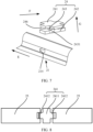
- the vertical fixing plate 243 may separate space between the upper fixing plate 241 and the lower fixing plate 242 into two grooves 246.
- the support body 24 may also be fabricated by using a casting method. Then, grooves 246 are separately processed on two opposite side surfaces of the support body 24 (as shown in FIG. 7 ).
- a plate surface shape of the upper fixing plate 241 may be a "cross" shape.
- the upper fixing plate 241 includes a fastening body 2411 and two convex portions 2412 respectively located on two sides of the fastening body 2411.
- a shape of the lower fixing plate 242 may be rectangular, and the lower fixing plate 242 is closer to the base 21 than the upper fixing plate 241.
- a size of the lower fixing plate 242 in the width direction F may be greater than a size in the length direction E.
- the lower fixing plate 242 is closer to the base 21 is not in contact with or not connected to the flexible display 30, and does not need to provide support for the flexible display 30. Therefore, a size of the lower fixing plate 242 in the length direction E may be less than a size of the upper fixing plate 241 in the length direction E. In this way, a weight of the lower fixing plate 242 can be reduced, and a weight of the foldable mobile phone can be reduced.
- a size of the vertical fixing plate 243 along the length direction E of the foldable mobile phone may be less than or equal to a size of the upper fixing plate 241 along the length direction E of the foldable mobile phone. In this way, a weight of the vertical fixing plate 243 can be further reduced as much as possible while satisfying connection strength between the upper fixing plate 241 and the lower fixing plate 242.
- a positioning hole 2431 is disposed on the lower fixing plate 242, and the positioning position 214 of the base 21 may be located in the positioning hole 2431.
- the support body 24 may slide along the thickness direction G of the foldable mobile phone.
- the positioning position 214 can provide lateral positioning for the support body 24, so as to alleviate the following case: The support body 24 generates excessive lateral displacement in a process of folding or unfolding the foldable mobile phone.
- a quantity of the positioning holes 2431 is the same as a quantity of the positioning positions 214, and locations are set in a one-to-one correspondence.
- a size of the lower fixing plate 242 in the length direction E of the foldable mobile phone is relatively small. Therefore, a lateral positioning function of the support body 24 can be implemented by disposing only one group of positioning position 214 and positioning hole 2431.
- the torsion swing arm 25 includes a first rotating portion 251, a rotating body 252, a second rotating portion 253, a connecting plate 254, and a coupling shaft 255, where the connecting plate 254 is fastened between the first rotating portion 251 and the second rotating portion 253, and the rotating body 252 is fastened to the first rotating portion 251.
- the first rotating portion 251 is fastened to the first rotating shaft 232
- the second rotating portion 253 is connected to the main swing arm 22 by using the coupling shaft 255 (not shown in FIG. 3 ).
- the first rotating portion 251 is fastened to a part that is of the first rotating shaft 232 and that has the rotating shaft incision 2321. As shown in FIG. 9 , a first through hole 2511 is disposed on an end face of the first rotating portion 251, and the first through hole 2511 is loosely fitted with the first rotating shaft 232 shown in FIG. 4 .
- the rotating shaft incision 2321 may be disposed inwardly from a side that is of the first rotating shaft 232 and that faces the support body 24. Because the first rotating shaft 232 and the support body 24 are generally arranged in the width direction F of the terminal device, a size of the first rotating shaft 232 along the width direction F of the terminal device can be reduced, and a width of the terminal device can be reduced.
- the first rotating shaft 232 may rotate around an axis of the first rotating shaft 232, and the torsion swing arm 25 may rotate with the first rotating shaft 232. Because the two gears 231 on the edges of the synchronization mechanism 23 are respectively fastened to the two first rotating shafts 232, and the four gears 231 rotate synchronously, the two first rotating shafts 232 also rotate synchronously, and the two torsion swing arms 25 respectively fastened to the two first rotating shafts 232 also rotate synchronously.
- the first side surface 2513 of the first rotating portion 251 extends inwardly and is provided with a rotating portion incision 2512, and the rotating portion incision 2512 is connected to the first through hole 2511.
- a second through hole 2531 is disposed on the second side surface 2514 of the second rotating portion 253, and the second through hole 2531 may be a circular hole. As shown in FIG. 3 , the second rotating portion 253 is farther from the base 21 than the first rotating portion 251.
- the connecting plate 254, the first rotating portion 251, the second rotating portion 253, and the rotating body 252 may be formed in an integrated molding manner or in a split molding manner.
- the entire torsion swing arm 25 may be fabricated by using a casting method.
- the first rotating portion 251, the second rotating portion 253, the connecting plate 254, and the rotating body 252 may be separately fabricated, and the four components are welded to the torsion swing arm 25.
- one end of the coupling shaft 255 is rotatably connected to the second rotating portion 253, and the other end is slidably connected to the chute 2231 of the second clamping portion 223 of the main swing arm 22.
- the coupling shaft 255 is located in a remote position that is in the chute 2231 and that is far away from the center of the base 21.
- the torsion swing arm 25 rotates around the first rotating shaft 232, and the main swing arm 22 moves along the circular arc surface of the blocking portion 213. Therefore, actual movement of the main swing arm 22 is swinging.
- the main swing arm 22 on the right further slides to the right.
- a distance between a distal end of the chute 2231 on the main swing arm 22 and the first rotating shaft 232 gradually increases, and a distance between the coupling shaft 255 and the first rotating shaft 232 remains unchanged. Therefore, as shown in FIG. 12 , in a moving process of the torsion swing arm 25 and the main swing arm 22, the coupling shaft 255 slides along the chute 2231 of the second clamping portion 223.
- the rotating body 252 is in a strip-like structure, and two end faces of the rotating body 252 are respectively fastened to two incision side walls 2515 of the rotating portion incision 2512. Therefore, a lateral size of the torsion swing arm 25 can be reduced, so that occupied space of the folding mechanism 20 in the width direction F of the foldable mobile phone is reduced.
- the rotating bodies 252 of the two torsion swing arms 25 are of a symmetrical structure about a center of the base 21.
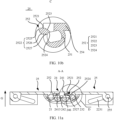
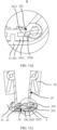
- a side surface of the rotating body 252 includes a first pressure surface 2521, a second pressure surface 2522, a third connection surface 2524, and a first connection surface 2523 that are sequentially connected to each other, and the first pressure surface 2521 is connected to the third connection surface 2524.
- the first pressure surface 2521 abuts against the upper fixing plate 241 of the support body 24.
- the second pressure surface 2522 includes a first plane 2525, a circular arc plane 2526, and a second plane 2527 that are sequentially connected. Both the first plane 2525 and the second plane 2527 are tangent to the circular arc plane 2526, the first plane 2525 is connected to the first pressure surface 2521, and the second plane 2527 is connected to the third connection surface 2524.
- the rotating body 252 can provide a force for the support body 24 to deviate from the base 21, so that an upper surface of the upper fixing plate 241 and an upper surface of the torsion swing arm 25 are located on a same plane, and jointly provide support for the flexible display 30 (not shown in FIG. 11a ).
- the first pressure surface 2521 may be a plane. In this way, when the foldable mobile phone is in a flattened state, fit between the first pressure surface 2521 and the upper fixing plate 241 is fit between planes. Therefore, the first pressure surface 2521 can provide stable support for the upper fixing plate 241.
- FIG. 11c is a schematic diagram of a structure of the folding mechanism 20 when the foldable mobile phone is folded to 100°.
- the first rotating shaft 232 rotates around an axis of the first rotating shaft 232
- the torsion swing arm 25 rotates with the first rotating shaft 232. Therefore, a rotation center of the torsion swing arm 25 is the axis of the first rotating shaft 232, and a rotation center of the rotating body 252 is also the axis of the first rotating shaft 232.
- the rotating body 252 rotates around the axis of the first rotating shaft 232, as shown in FIG.
- the circular arc surface 2526 gradually is in contact with the lower fixing plate 242.
- the foldable mobile phone continues to fold, the rotating body 252 continues to rotate, and the circular arc surface 2526 of the rotating body 252 on the right side rotates downward to the right, and the circular arc surface 2526 is always in an tangent state with the upper surface 2421 of the lower fixing plate 242, and provides a force for the lower fixing plate 242 to move toward the base 21.
- the lower fixing plate 242 may move toward the base 21 under the action of the force, that is, move in a direction that is away from the flexible display 30 (not shown in FIG. 11d ).
- the rotating body 252 continues to rotate until the foldable mobile phone is in a folded state. As shown in FIG. 11e and FIG. 11f , when the foldable mobile phone is folded into a folded state, the first plane 2525 of the rotating body 252 still abuts against the lower fixing plate 242, so as to continue to provide a force toward the base 21 for the support body 24. Because both the first plane 2525 and the upper surface 2421 of the lower fixing plate 242 are planes, an action between the rotating body 252 and the lower fixing plate 242 is an action between planes.
- the rotating body 252 can provide a stable force for the lower fixing plate 242 by using the first plane 2525, and the support body 24 is suspended in the position, so that the support body 24 avoids a bent area of the flexible display 30 (not shown in FIG. 11e and FIG. 11f ). Because the folding mechanism 20 in this embodiment of this application does not need to use a spring, space required when the spring is compressed to a limit does not need to be reserved. That is, in this embodiment of this application, space in the thickness direction G of the foldable mobile phone can be reduced, and a thickness of the foldable mobile phone is further reduced.
- the rotating body 252 on the right side rotates clockwise with the first rotating shaft 232.
- the rotating body 252 rotates until the first pressure surface 2521 is in contact with the lower surface 2413 of the upper fixing plate 241, the rotating body 252 continues to rotate, and the rotating body 252 may provide a force for the upper fixing plate 241 to deviate from the base 21.
- the upper fixing plate 241 may move to be flush with the upper surface of the torsion arm 25 under the action of the force of the rotating body 252.
- the third connection surface 2524 of the rotating body 252 is a surface facing the first rotating shaft 232.
- the third connection surface 2524 is in contact with or has a clearance with the first rotating shaft 232. In this way, interference between parts can be avoided, and it is convenient to assemble the torsion swing arm 25 and the first rotating shaft 232.
- the rotating body 252 includes the third connection surface 2524, the first connection surface 2523, the first pressure surface 2521, and a second connection surface 2528 that are sequentially connected, and the third connection surface 2524 is connected to the second connection surface 2528.
- the first pressure surface 2521 is a circular arc surface.
- the rotating body 252 rotates with the first rotating shaft 232, the rotating body 252 moves until the first pressure surface 2521 abuts against the upper surface 2421 of the lower fixing plate 242.
- the rotating body 252 continues to rotate, a force toward the base 21 may be provided for the lower fixing plate 242.
- the lower fixing plate 242 moves toward the base 21 under the action of the force until the foldable mobile phone is in a folded state, the rotating body 252 stops moving, and the lower fixing plate 242 also stops moving.
- the rotating body 252 may continuously provide a force for the lower fixing plate 242, so that the lower fixing plate 242 is suspended in the position, thereby avoiding a bent area of the flexible display 30 (not shown in FIG. 14a ).
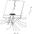
- a difference from the embodiment shown in FIG. 3 lies in a structure of the upper fixing plate 241 of the support body 24, quantities of first rotating portions 251 and the rotating bodies 252 in the torsion swing arm 25, and a structure of the connecting plate 254.
- the upper fixing plate 241 is in a strip-like structure; the upper fixing plate 241 may include the fastening body 2411 and four convex portions 2412 located on the sides of the fixing body 2411; and there are two convex portions 2412 of each side of the fastening body 2411, and the two convex portions 2412 are arranged along the side of the fixing body 2411. In another embodiment, there may be three or more convex portions 2412 on one side of the fastening body 2411.
- quantities of the first rotating portions 251 and the rotating bodies 252 in the torsion swing arm 25 are the same as a quantity of the convex portions 2412 arranged on one side of the upper fixing plate 241, and they are two.
- the two first rotating portions 251 and the rotating bodies 252 are arranged along the length direction E.
- the connecting plate 254 has a large connection area, and connects the two first rotating portions 251 and the second rotating portion 253.
- a contact area between the support body 24 and the flexible display 30 (not shown in FIG. 15a ) is larger, so that more stable support can be provided for the flexible display 30.
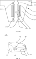
- the support body 24 includes the upper fixing plate 241, the lower fixing plate 242, the vertical fixing plate 243, and two side fixing plates 244.
- the upper fixing plate 241 and the lower fixing plate 242 are parallel to each other, the vertical fixing plate 243 is fastened between the upper fixing plate 241 and the lower fixing plate 242, and the vertical fixing plate 243 are perpendicular to both the upper fixing plate 241 and the lower fixing plate 242.
- the lower fixing plate 242 is closer to the base 21 than the upper fixing plate 241.
- the two side fixing plates 244 are respectively fastened on two sides of the upper fixing plate 241 and the lower fixing plate 242, and each side fixing plate 244 and the upper fixing plate 241 and the lower fixing plate 242 may form an accommodating cavity 245 that has closed sides and open ends. Therefore, two accommodating cavities 245 are formed on the support body 24.
- the first rotating portion 251 has the first side surface 2513 that is away from the second rotating portion 253, the first side surface 2513 is a plane, and the rotating body 252 is fastened to the first side surface 2513 of the first rotating portion 251.
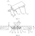
- the rotating body 252 includes a connector 2529 and a fixing post 2530, where the connector 2529 is fastened to the first side surface 2513, and the fixing post 2530 is fastened to a surface that is of the connector 2529 and that faces the support body 24.
- the connector 2529 may be a strip-like plate structure. As shown in FIG. 18 , a length direction of the connector 2529 extends toward the support body 24.
- one end of the fixing post 2530 is fastened to the connector 2529.
- the other end of the fixing post 2530 extends into the accommodating cavity 245 of the support body 24, and when the foldable mobile phone is in a flattened state, the fixing post 2530 abuts against the lower surface 2413 of the upper fixing plate 241. In this way, the fixing post 2530 can provide a force for the support body 24 to deviate from the base 21, so that the support body 24 provides support for the flexible display 30 (not shown in FIG. 17 ).
- the rotating body 252 rotates with the first rotating shaft 232, and when the rotating body 252 continues to rotate when a surface of the rotating body 252 abuts against the upper surface 2421 of the lower fixing plate 242, the rotating body 252 continues to rotate, a force toward the base 21 may be provided for the lower fixing plate 242, and the lower fixing plate 242 moves toward the base 21 under the action of the force.
- the rotating body 252 stops moving, and the lower fixing plate 242 stops moving.
- the rotating body 252 may continuously provide a force for the lower fixing plate 242, so that the lower fixing plate 242 is suspended in the position, thereby avoiding a bent area of the flexible display 30.
- the folding mechanism 20 in this embodiment of this application does not need to use a spring, space required when the spring is compressed to a limit does not need to be reserved. That is, in this embodiment of this application, space in the thickness direction G of the foldable mobile phone can be reduced, and a thickness of the foldable mobile phone is further reduced.
Landscapes
- Engineering & Computer Science (AREA)
- Computer Hardware Design (AREA)
- Theoretical Computer Science (AREA)
- General Engineering & Computer Science (AREA)
- Human Computer Interaction (AREA)
- Physics & Mathematics (AREA)
- General Physics & Mathematics (AREA)
- Signal Processing (AREA)
- Mechanical Engineering (AREA)
- Telephone Set Structure (AREA)
Claims (13)
- Ein Faltmechanismus (20) für ein faltbares Mobiltelefon, umfassend:eine Basis (21);einen Trägerkörper (24), wobei der Trägerkörper (24) mit der Basis (21) verbunden ist, mit einer ersten Nut (246) und einer zweiten Nut (246) versehen ist, die einander in Position entsprechen, und der Trägerkörper sich zur Basis hin oder von ihr weg bewegen kann;einen ersten Schwenkarm (22, 25), wobei der erste Schwenkarm einen ersten Drehabschnitt (25) und einen ersten Drehkörper (22) umfasst, der am ersten Drehabschnitt (25) befestigt ist, der erste Drehabschnitt (25) drehbar mit der Basis (21) verbunden ist, ein Teil des ersten Drehkörpers (22) in die erste Nut (246) hineinragt und der erste Drehkörper (22) so konfiguriert ist, dass er während eines Drehvorgangs eine Kraft auf den Trägerkörper (24) ausübt, sodass sich der Trägerkörper (24) zur Basis (21) hin oder von ihr weg bewegt; undeinen zweiten Schwenkarm (22, 25), wobei der zweite Schwenkarm einen zweiten Drehabschnitt (25) und einen zweiten Drehkörper (22) umfasst, der am zweiten Drehabschnitt (25) befestigt ist, der zweite Drehabschnitt (25) drehbar mit der Basis (21) verbunden ist, ein Teil des zweiten Drehkörpers (22) in die zweite Nut (246) hineinragt und der zweite Drehkörper (22) so konfiguriert ist, dass er während eines Drehvorgangs eine Kraft auf den Trägerkörper (24) ausübt, sodass sich der Trägerkörper (24) zur Basis (21) hin oder von ihr weg bewegt;wobei der Trägerkörper (24) eine erste Befestigungsplatte (241) und eine zweite Befestigungsplatte (242) umfasst, die einander gegenüberliegen, sowie eine dritte Befestigungsplatte (243), die zwischen der ersten Befestigungsplatte (241) und der zweiten Befestigungsplatte (242) verbunden ist, und die dritte Befestigungsplatte (243) den Raum zwischen der ersten Befestigungsplatte (241) und der zweiten Befestigungsplatte (242) in die erste Nut (246) und die zweite Nut (246) unterteilt; undwobei die zweite Befestigungsplatte (242) näher an der Basis (21) liegt als die erste Befestigungsplatte (241), die Größe der zweiten Befestigungsplatte (242) in einer zweiten Richtung (F) größer ist als die Größe der zweiten Befestigungsplatte (242) in einer ersten Richtung (E), die senkrecht zur zweiten Richtung (F) steht, die Größe der zweiten Befestigungsplatte (242) in der ersten Richtung (E) kleiner ist als die Größe der ersten Befestigungsplatte (241) in der ersten Richtung (E), und wobei der erste Drehabschnitt (25) des ersten Schwenkarms (22, 25) und der zweite Drehabschnitt (25) des zweiten Schwenkarms (22, 25) so konfiguriert sind, dass sie sich um Achsen drehen, die in der ersten Richtung (E) orientiert sind.
- Der Faltmechanismus gemäß Anspruch 1, wobei die erste Befestigungsplatte eine erste Oberfläche aufweist, die der zweiten Befestigungsplatte zugewandt ist; und
Der erste rotierende Körper umfasst eine erste Druckfläche, und wenn sich der erste Schwenkarm und der zweite Schwenkarm in einem abgeflachten Zustand befinden, liegt die erste Druckfläche an der ersten Oberfläche an. - Der Faltmechanismus nach Anspruch 3, wobei die zweite Befestigungsplatte eine zweite Oberfläche aufweist, die der ersten Befestigungsplatte zugewandt ist; und
Der erste rotierende Körper umfasst ferner eine zweite Druckfläche, die mit der ersten Druckfläche verbunden ist, und während des Faltvorgangs des ersten Schwenkarms und des zweiten Schwenkarms interagiert die zweite Druckfläche mit der zweiten Oberfläche. - Der Faltmechanismus nach Anspruch 2 oder 3, wobei die erste Druckfläche eine erste Ebene umfasst.
- Der Faltmechanismus nach Anspruch 3, wobei die zweite Druckfläche eine zweite Ebene umfasst, die zweite Ebene mit der ersten Druckfläche verbunden ist, und wenn sich der erste Schwenkarm und der zweite Schwenkarm in einem gefalteten Zustand befinden, liegt die zweite Ebene an der zweiten Oberfläche an;wobei die zweite Druckfläche ferner eine erste Bogenfläche umfasst, die mit der zweiten Ebene verbunden ist und nach außen hervorsteht;wobei die zweite Druckfläche ferner eine dritte Ebene umfasst, die mit der ersten Bogenfläche verbunden ist, und die dritte Ebene ist ferner so konfiguriert, dass, wenn sich der erste Schwenkarm und der zweite Schwenkarm in einem abgeflachten Zustand befinden, ein Teil der dritten Ebene an der zweiten Oberfläche anliegt.
- Der Faltmechanismus nach Anspruch 3, wobei die erste Druckfläche und die zweite Druckfläche verbunden sind, um eine zweite Bogenfläche zu bilden, und während des Faltvorgangs des ersten Schwenkarms und des zweiten Schwenkarms interagiert die zweite Bogenfläche mit der zweiten Oberfläche; und während des Entfaltungsvorgangs des ersten Schwenkarms und des zweiten Schwenkarms interagiert die zweite Bogenfläche mit der ersten Oberfläche.
- Der Faltmechanismus nach Anspruch 1, wobei der erste rotierende Körper einen Verbinder und ein Befestigungselement umfasst, das am Verbinder befestigt ist, wobei sich mindestens ein Teil des Befestigungselements in die erste Nut erstreckt, und das Befestigungselement so konfiguriert ist, dass es eine Kraft bereitstellt, um den Trägerkörper während eines Rotationsvorgangs in Richtung auf oder von der Basis weg zu bewegen;
wobei sich der Verbinder auf einer Seitenfläche des Trägerkörpers befindet, das Befestigungselement zur Seitenfläche hin angeordnet ist, und die Seitenfläche eine Fläche ist, die an eine Seite angrenzt, auf der sich der erste Schwenkarm befindet. - Der Faltmechanismus nach einem der Ansprüche 1 bis 7, wobei eine erste Einschnitt an einer ersten Seitenfläche des ersten Drehteils angeordnet ist, ein Teil des ersten Drehkörpers in die erste Einschnitt hineinragt und die erste Seitenfläche eine Fläche des ersten Drehkörpers ist, die der zweiten Drehteil gegenüberliegt, wenn der erste Schwenkarm und der zweite Schwenkarm in einem abgeflachten Zustand sind.wobei die erste Einschnitt zwei gegenüberliegende Seitenwände aufweist und der erste Drehkörper an den beiden Seitenwänden befestigt ist;wobei die erste Befestigungsplatte einen Befestigungskörper und einen konvexen Abschnitt umfasst, der an einer Seite des Befestigungskörpers befestigt ist, und ein Teil des konvexen Abschnitts in die erste Einschnitt hineinragt;wobei ein erstes Durchgangsloch an einer zweiten Seitenfläche des ersten Drehteils angeordnet ist, die zweite Seitenfläche an die erste Seitenfläche angrenzt und die erste Einschnitt mit dem ersten Durchgangsloch verbunden ist; undder erste Drehkörper ferner eine Verbindungsfläche aufweist, die dem ersten Durchgangsloch zugewandt ist, und eine Projektion der Verbindungsfläche auf der Seitenwand in Kontakt mit oder mit einem Abstand zu einer Kante einer Projektion des ersten Durchgangslochs auf der Seitenwand steht.
- Der Faltmechanismus nach einem der Ansprüche 1 bis 8, wobei es eine Vielzahl von ersten Drehkörpern gibt, es eine Vielzahl von ersten Rillen gibt und mindestens zwei erste Drehkörper in einer Eins-zu-eins-Entsprechung mit zwei ersten Rillen stehen; und/oder
es gibt eine Vielzahl von zweiten Drehkörpern, es gibt eine Vielzahl von zweiten Rillen, und mindestens zwei zweite Drehkörper stehen in einer Eins-zu-eins-Entsprechung mit zwei zweiten Rillen. - Der Faltmechanismus nach Anspruch 1, wobei der Faltmechanismus ferner einen dritten Schwenkarm umfasst, der dritte Schwenkarm mit der Basis so verbunden ist, dass der dritte Schwenkarm entlang der Bogenfläche gleiten kann, der dritte Schwenkarm und der erste Schwenkarm in der zweiten Richtung angeordnet sind, und der dritte Schwenkarm mit dem ersten Schwenkarm verbunden ist, sodass sich der dritte Schwenkarm relativ zur Basis synchron mit dem ersten Schwenkarm bewegt; und/oderder Faltmechanismus ferner einen vierten Schwenkarm umfasst, und der vierte Schwenkarm mit der Basis so verbunden ist, dass der dritte Schwenkarm entlang der Bogenfläche gleiten kann; und der vierte Schwenkarm und der zweite Schwenkarm in der zweiten Richtung angeordnet sind, und der vierte Schwenkarm mit dem zweiten Schwenkarm verbunden ist, sodass sich der vierte Schwenkarm relativ zur Basis synchron mit dem zweiten Schwenkarm bewegt; unddie zweite Richtung steht senkrecht zur Bewegungsrichtung des Trägerkörpers.
- Der Faltmechanismus nach Anspruch 10, wobei eine erste Rutsche auf einer Oberfläche angeordnet ist, die sich am dritten Schwenkarm befindet und dem ersten Schwenkarm zugewandt ist; undder erste Schwenkarm umfasst ferner einen dritten Drehabschnitt, der am ersten Drehabschnitt befestigt ist, und eine erste Kupplungswelle, die drehbar mit dem dritten Drehabschnitt verbunden ist, wobei ein Teil der ersten Kupplungswelle in die erste Rutsche hineinragt;wobei eine zweite Rutsche auf einer Oberfläche angeordnet ist, die sich am vierten Schwenkarm befindet und dem zweiten Schwenkarm zugewandt ist; undder zweite Schwenkarm umfasst ferner einen vierten Drehabschnitt, der am zweiten Drehabschnitt befestigt ist, und eine zweite Kupplungswelle, die drehbar mit dem dritten Drehabschnitt verbunden ist, wobei ein Teil der zweiten Kupplungswelle in die zweite Rutsche hineinragt.
- Der Faltmechanismus nach einem der Ansprüche 1 bis 9, wobei der erste Schwenkarm und der zweite Schwenkarm symmetrisch zu einer Mittelebene des Trägerkörpers sind, und die Mittelebene ist eine Ebene, die sich im geometrischen Zentrum des Trägerkörpers befindet und die senkrecht zur ersten Richtung steht.
- Eine Endvorrichtung, wobei die Endvorrichtung den Faltmechanismus nach einem der Ansprüche 1 bis 12 umfasst.
Applications Claiming Priority (2)
| Application Number | Priority Date | Filing Date | Title |
|---|---|---|---|
| CN202111434016.XA CN115013421B (zh) | 2021-11-29 | 2021-11-29 | 折叠机构及终端设备 |
| PCT/CN2022/118815 WO2023093226A1 (zh) | 2021-11-29 | 2022-09-14 | 折叠机构及终端设备 |
Publications (3)
| Publication Number | Publication Date |
|---|---|
| EP4215767A1 EP4215767A1 (de) | 2023-07-26 |
| EP4215767A4 EP4215767A4 (de) | 2024-05-01 |
| EP4215767B1 true EP4215767B1 (de) | 2025-03-26 |
Family
ID=83065099
Family Applications (1)
| Application Number | Title | Priority Date | Filing Date |
|---|---|---|---|
| EP22844419.6A Active EP4215767B1 (de) | 2021-11-29 | 2022-09-14 | Klappmechanismus und endgerätevorrichtung |
Country Status (4)
| Country | Link |
|---|---|
| US (1) | US12608051B2 (de) |
| EP (1) | EP4215767B1 (de) |
| CN (1) | CN115013421B (de) |
| WO (1) | WO2023093226A1 (de) |
Families Citing this family (12)
| Publication number | Priority date | Publication date | Assignee | Title |
|---|---|---|---|---|
| CN113067924B (zh) * | 2021-03-19 | 2023-05-23 | 维沃移动通信有限公司 | 折叠机构、支架结构和电子设备 |
| CN115013421B (zh) | 2021-11-29 | 2023-04-14 | 荣耀终端有限公司 | 折叠机构及终端设备 |
| CN114244934B (zh) * | 2021-12-29 | 2024-08-06 | 维沃移动通信有限公司 | 电子设备 |
| CN117722430A (zh) * | 2022-09-09 | 2024-03-19 | 深圳富泰宏精密工业有限公司 | 转轴结构以及电子装置 |
| CN117780773A (zh) * | 2022-09-27 | 2024-03-29 | 荣耀终端有限公司 | 一种转轴组件及终端设备 |
| CN116658512B (zh) * | 2022-10-27 | 2024-03-29 | 荣耀终端有限公司 | 转动机构和可折叠电子设备 |
| CN115750579B (zh) * | 2022-11-08 | 2026-04-14 | 维沃移动通信有限公司 | 铰链机构及电子设备 |
| CN117989220B (zh) * | 2022-11-30 | 2025-03-25 | 荣耀终端股份有限公司 | 折叠组件、折叠装置及终端设备 |
| CN117847076B (zh) * | 2023-03-22 | 2025-05-16 | 荣耀终端股份有限公司 | 转轴机构及终端设备 |
| WO2025048120A1 (ko) * | 2023-08-30 | 2025-03-06 | 삼성전자 주식회사 | 힌지 어셈블리를 포함하는 전자 장치 |
| CN120027126A (zh) * | 2023-11-13 | 2025-05-23 | 荣耀终端股份有限公司 | 转轴机构、可折叠设备及转轴机构的制备方法 |
| CN118669421B (zh) * | 2024-07-31 | 2024-12-31 | 荣耀终端有限公司 | 一种同步机构、转轴机构及电子设备 |
Family Cites Families (16)
| Publication number | Priority date | Publication date | Assignee | Title |
|---|---|---|---|---|
| CN205750631U (zh) * | 2016-01-19 | 2016-11-30 | 杭州安费诺飞凤通信部品有限公司 | 柔性屏支撑铰链、柔性屏装置及移动终端 |
| TWM551804U (zh) * | 2017-06-08 | 2017-11-11 | First Dome Corp | 鉸鏈及具有該鉸鏈的折疊式電子裝置 |
| US10863641B2 (en) * | 2017-12-04 | 2020-12-08 | Lg Display Co., Ltd. | Foldable display apparatus |
| CN207777905U (zh) * | 2017-12-06 | 2018-08-28 | 杭州安费诺飞凤通信部品有限公司 | 一种内折柔性屏移动终端的铰链及内折柔性屏移动终端 |
| CN108922408B (zh) | 2018-09-19 | 2024-02-27 | 云谷(固安)科技有限公司 | 一种可折叠支撑装置及可折叠柔性显示装置 |
| TWI681284B (zh) | 2018-12-25 | 2020-01-01 | 富世達股份有限公司 | 樞轉機構及可撓式電子裝置 |
| CN111629087B (zh) * | 2019-02-28 | 2025-02-11 | Oppo广东移动通信有限公司 | 折叠式移动终端 |
| US11337321B2 (en) * | 2019-02-28 | 2022-05-17 | Guangdong Oppo Mobile Telecommunications Corp., Ltd. | Foldable terminal |
| CN111698355B (zh) | 2019-03-15 | 2021-07-09 | 华为技术有限公司 | 一种转轴机构及移动终端 |
| CN112153178A (zh) * | 2019-06-27 | 2020-12-29 | 华为技术有限公司 | 一种转轴机构及可折叠移动终端 |
| CN113542456B (zh) * | 2020-04-15 | 2022-09-23 | 华为技术有限公司 | 折叠装置及电子设备 |
| CN213270695U (zh) * | 2020-05-12 | 2021-05-25 | 杭州安费诺飞凤通信部品有限公司 | 一种应用于内折柔性屏终端的运动机构 |
| CN111885235B (zh) * | 2020-07-25 | 2022-01-11 | Oppo广东移动通信有限公司 | 可折叠壳体组件及可折叠电子设备 |
| CN213028129U (zh) * | 2020-08-06 | 2021-04-20 | 比亚迪股份有限公司 | 一种折叠机构及柔性屏移动终端 |
| CN112901649B (zh) * | 2021-03-09 | 2024-12-31 | 东莞市环力智能科技有限公司 | 一种三段式内折叠铰链 |
| CN115013421B (zh) | 2021-11-29 | 2023-04-14 | 荣耀终端有限公司 | 折叠机构及终端设备 |
-
2021
- 2021-11-29 CN CN202111434016.XA patent/CN115013421B/zh active Active
-
2022
- 2022-09-14 US US18/019,331 patent/US12608051B2/en active Active
- 2022-09-14 EP EP22844419.6A patent/EP4215767B1/de active Active
- 2022-09-14 WO PCT/CN2022/118815 patent/WO2023093226A1/zh not_active Ceased
Also Published As
| Publication number | Publication date |
|---|---|
| CN115013421A (zh) | 2022-09-06 |
| EP4215767A4 (de) | 2024-05-01 |
| US20250258522A1 (en) | 2025-08-14 |
| US12608051B2 (en) | 2026-04-21 |
| WO2023093226A1 (zh) | 2023-06-01 |
| EP4215767A1 (de) | 2023-07-26 |
| CN115013421B (zh) | 2023-04-14 |
Similar Documents
| Publication | Publication Date | Title |
|---|---|---|
| EP4215767B1 (de) | Klappmechanismus und endgerätevorrichtung | |
| EP3955555A1 (de) | Drehwellenmechanismus und faltbares mobiles endgerät | |
| CN114046313B (zh) | 铰链、显示面板及电子装置 | |
| EP4124002A1 (de) | Faltvorrichtung und elektronische vorrichtung | |
| US20250071196A1 (en) | Hinge Mechanism and Foldable Device | |
| CN115665293A (zh) | 折叠装置及电子设备 | |
| JP7479505B2 (ja) | フレーム構造、スクリーンコンポーネントと電子機器 | |
| EP4180677B1 (de) | Drehwellenmechanismus und elektronische vorrichtung | |
| US12556625B2 (en) | Rotating shaft mechanism and terminal device | |
| WO2024114669A1 (zh) | 折叠组件、折叠装置及终端设备 | |
| US20250159819A1 (en) | Folding assembly, folding apparatus, and terminal device | |
| EP4650612A1 (de) | Drehwellenmechanismus, faltvorrichtung und endgerätevorrichtung | |
| WO2023138402A9 (zh) | 一种同步机构、转轴机构和电子设备 | |
| WO2023231393A1 (zh) | 折叠装置、壳体组件及电子设备 | |
| JP2024542627A (ja) | 回転シャフト機構および電子デバイス | |
| EP4269825B1 (de) | Faltanordnung und elektronische vorrichtung | |
| CN117189766A (zh) | 折叠装置、壳体组件及电子设备 | |
| CN117189763A (zh) | 折叠装置、壳体组件及电子设备 | |
| CN116398534B (zh) | 铰链机构和电子设备 | |
| EP4697686A1 (de) | Klappmechanismus und elektronische vorrichtung | |
| CN114613255B (zh) | 转动机构、柔性显示装置及电子设备 | |
| CN116771789A (zh) | 转轴组件及电子设备 | |
| CN223447458U (zh) | 铰链组件、折叠屏、中控屏模组以及车辆 | |
| HK40074398A (en) | Folding mechanism and terminal device | |
| EP4561033A1 (de) | Elektronische vorrichtung und faltanordnung |
Legal Events
| Date | Code | Title | Description |
|---|---|---|---|
| STAA | Information on the status of an ep patent application or granted ep patent |
Free format text: STATUS: UNKNOWN |
|
| STAA | Information on the status of an ep patent application or granted ep patent |
Free format text: STATUS: THE INTERNATIONAL PUBLICATION HAS BEEN MADE |
|
| PUAI | Public reference made under article 153(3) epc to a published international application that has entered the european phase |
Free format text: ORIGINAL CODE: 0009012 |
|
| STAA | Information on the status of an ep patent application or granted ep patent |
Free format text: STATUS: REQUEST FOR EXAMINATION WAS MADE |
|
| 17P | Request for examination filed |
Effective date: 20230126 |
|
| AK | Designated contracting states |
Kind code of ref document: A1 Designated state(s): AL AT BE BG CH CY CZ DE DK EE ES FI FR GB GR HR HU IE IS IT LI LT LU LV MC MK MT NL NO PL PT RO RS SE SI SK SM TR |
|
| REG | Reference to a national code |
Ref country code: DE Ref legal event code: R079 Free format text: PREVIOUS MAIN CLASS: F16C0011040000 Ipc: H04M0001020000 Ref country code: DE Ref legal event code: R079 Ref document number: 602022012385 Country of ref document: DE Free format text: PREVIOUS MAIN CLASS: F16C0011040000 Ipc: H04M0001020000 |
|
| RIC1 | Information provided on ipc code assigned before grant |
Ipc: F16C 11/04 20060101ALI20240102BHEP Ipc: G06F 1/16 20060101ALI20240102BHEP Ipc: H04M 1/02 20060101AFI20240102BHEP |
|
| A4 | Supplementary search report drawn up and despatched |
Effective date: 20240405 |
|
| RIC1 | Information provided on ipc code assigned before grant |
Ipc: F16C 11/04 20060101ALI20240328BHEP Ipc: G06F 1/16 20060101ALI20240328BHEP Ipc: H04M 1/02 20060101AFI20240328BHEP |
|
| GRAP | Despatch of communication of intention to grant a patent |
Free format text: ORIGINAL CODE: EPIDOSNIGR1 |
|
| STAA | Information on the status of an ep patent application or granted ep patent |
Free format text: STATUS: GRANT OF PATENT IS INTENDED |
|
| DAV | Request for validation of the european patent (deleted) | ||
| DAX | Request for extension of the european patent (deleted) | ||
| INTG | Intention to grant announced |
Effective date: 20241025 |
|
| GRAS | Grant fee paid |
Free format text: ORIGINAL CODE: EPIDOSNIGR3 |
|
| GRAA | (expected) grant |
Free format text: ORIGINAL CODE: 0009210 |
|
| STAA | Information on the status of an ep patent application or granted ep patent |
Free format text: STATUS: THE PATENT HAS BEEN GRANTED |
|
| AK | Designated contracting states |
Kind code of ref document: B1 Designated state(s): AL AT BE BG CH CY CZ DE DK EE ES FI FR GB GR HR HU IE IS IT LI LT LU LV MC MK MT NL NO PL PT RO RS SE SI SK SM TR |
|
| REG | Reference to a national code |
Ref country code: GB Ref legal event code: FG4D |
|
| REG | Reference to a national code |
Ref country code: CH Ref legal event code: EP |
|
| REG | Reference to a national code |
Ref country code: DE Ref legal event code: R096 Ref document number: 602022012385 Country of ref document: DE |
|
| REG | Reference to a national code |
Ref country code: IE Ref legal event code: FG4D |
|
| REG | Reference to a national code |
Ref country code: NL Ref legal event code: FP |
|
| PG25 | Lapsed in a contracting state [announced via postgrant information from national office to epo] |
Ref country code: RS Free format text: LAPSE BECAUSE OF FAILURE TO SUBMIT A TRANSLATION OF THE DESCRIPTION OR TO PAY THE FEE WITHIN THE PRESCRIBED TIME-LIMIT Effective date: 20250626 |
|
| PG25 | Lapsed in a contracting state [announced via postgrant information from national office to epo] |
Ref country code: FI Free format text: LAPSE BECAUSE OF FAILURE TO SUBMIT A TRANSLATION OF THE DESCRIPTION OR TO PAY THE FEE WITHIN THE PRESCRIBED TIME-LIMIT Effective date: 20250326 |
|
| REG | Reference to a national code |
Ref country code: LT Ref legal event code: MG9D |
|
| PG25 | Lapsed in a contracting state [announced via postgrant information from national office to epo] |
Ref country code: NO Free format text: LAPSE BECAUSE OF FAILURE TO SUBMIT A TRANSLATION OF THE DESCRIPTION OR TO PAY THE FEE WITHIN THE PRESCRIBED TIME-LIMIT Effective date: 20250626 |
|
| PG25 | Lapsed in a contracting state [announced via postgrant information from national office to epo] |
Ref country code: HR Free format text: LAPSE BECAUSE OF FAILURE TO SUBMIT A TRANSLATION OF THE DESCRIPTION OR TO PAY THE FEE WITHIN THE PRESCRIBED TIME-LIMIT Effective date: 20250326 |
|
| PG25 | Lapsed in a contracting state [announced via postgrant information from national office to epo] |
Ref country code: LV Free format text: LAPSE BECAUSE OF FAILURE TO SUBMIT A TRANSLATION OF THE DESCRIPTION OR TO PAY THE FEE WITHIN THE PRESCRIBED TIME-LIMIT Effective date: 20250326 |
|
| PG25 | Lapsed in a contracting state [announced via postgrant information from national office to epo] |
Ref country code: GR Free format text: LAPSE BECAUSE OF FAILURE TO SUBMIT A TRANSLATION OF THE DESCRIPTION OR TO PAY THE FEE WITHIN THE PRESCRIBED TIME-LIMIT Effective date: 20250627 Ref country code: BG Free format text: LAPSE BECAUSE OF FAILURE TO SUBMIT A TRANSLATION OF THE DESCRIPTION OR TO PAY THE FEE WITHIN THE PRESCRIBED TIME-LIMIT Effective date: 20250326 |
|
| PG25 | Lapsed in a contracting state [announced via postgrant information from national office to epo] |
Ref country code: SE Free format text: LAPSE BECAUSE OF FAILURE TO SUBMIT A TRANSLATION OF THE DESCRIPTION OR TO PAY THE FEE WITHIN THE PRESCRIBED TIME-LIMIT Effective date: 20250326 |
|
| PGFP | Annual fee paid to national office [announced via postgrant information from national office to epo] |
Ref country code: NL Payment date: 20250814 Year of fee payment: 4 |
|
| REG | Reference to a national code |
Ref country code: AT Ref legal event code: MK05 Ref document number: 1780120 Country of ref document: AT Kind code of ref document: T Effective date: 20250326 |
|
| PG25 | Lapsed in a contracting state [announced via postgrant information from national office to epo] |
Ref country code: SM Free format text: LAPSE BECAUSE OF FAILURE TO SUBMIT A TRANSLATION OF THE DESCRIPTION OR TO PAY THE FEE WITHIN THE PRESCRIBED TIME-LIMIT Effective date: 20250326 |
|
| PG25 | Lapsed in a contracting state [announced via postgrant information from national office to epo] |
Ref country code: ES Free format text: LAPSE BECAUSE OF FAILURE TO SUBMIT A TRANSLATION OF THE DESCRIPTION OR TO PAY THE FEE WITHIN THE PRESCRIBED TIME-LIMIT Effective date: 20250326 Ref country code: PT Free format text: LAPSE BECAUSE OF FAILURE TO SUBMIT A TRANSLATION OF THE DESCRIPTION OR TO PAY THE FEE WITHIN THE PRESCRIBED TIME-LIMIT Effective date: 20250728 |
|
| PGFP | Annual fee paid to national office [announced via postgrant information from national office to epo] |
Ref country code: DE Payment date: 20250730 Year of fee payment: 4 |
|
| PG25 | Lapsed in a contracting state [announced via postgrant information from national office to epo] |
Ref country code: IT Free format text: LAPSE BECAUSE OF FAILURE TO SUBMIT A TRANSLATION OF THE DESCRIPTION OR TO PAY THE FEE WITHIN THE PRESCRIBED TIME-LIMIT Effective date: 20250326 Ref country code: PL Free format text: LAPSE BECAUSE OF FAILURE TO SUBMIT A TRANSLATION OF THE DESCRIPTION OR TO PAY THE FEE WITHIN THE PRESCRIBED TIME-LIMIT Effective date: 20250326 |
|
| PG25 | Lapsed in a contracting state [announced via postgrant information from national office to epo] |
Ref country code: AT Free format text: LAPSE BECAUSE OF FAILURE TO SUBMIT A TRANSLATION OF THE DESCRIPTION OR TO PAY THE FEE WITHIN THE PRESCRIBED TIME-LIMIT Effective date: 20250326 |
|
| PG25 | Lapsed in a contracting state [announced via postgrant information from national office to epo] |
Ref country code: EE Free format text: LAPSE BECAUSE OF FAILURE TO SUBMIT A TRANSLATION OF THE DESCRIPTION OR TO PAY THE FEE WITHIN THE PRESCRIBED TIME-LIMIT Effective date: 20250326 |
|
| PG25 | Lapsed in a contracting state [announced via postgrant information from national office to epo] |
Ref country code: RO Free format text: LAPSE BECAUSE OF FAILURE TO SUBMIT A TRANSLATION OF THE DESCRIPTION OR TO PAY THE FEE WITHIN THE PRESCRIBED TIME-LIMIT Effective date: 20250326 |
|
| PG25 | Lapsed in a contracting state [announced via postgrant information from national office to epo] |
Ref country code: SK Free format text: LAPSE BECAUSE OF FAILURE TO SUBMIT A TRANSLATION OF THE DESCRIPTION OR TO PAY THE FEE WITHIN THE PRESCRIBED TIME-LIMIT Effective date: 20250326 |
|
| PG25 | Lapsed in a contracting state [announced via postgrant information from national office to epo] |
Ref country code: IS Free format text: LAPSE BECAUSE OF FAILURE TO SUBMIT A TRANSLATION OF THE DESCRIPTION OR TO PAY THE FEE WITHIN THE PRESCRIBED TIME-LIMIT Effective date: 20250726 |
|
| REG | Reference to a national code |
Ref country code: DE Ref legal event code: R097 Ref document number: 602022012385 Country of ref document: DE |
|
| PG25 | Lapsed in a contracting state [announced via postgrant information from national office to epo] |
Ref country code: DK Free format text: LAPSE BECAUSE OF FAILURE TO SUBMIT A TRANSLATION OF THE DESCRIPTION OR TO PAY THE FEE WITHIN THE PRESCRIBED TIME-LIMIT Effective date: 20250326 |
|
| PG25 | Lapsed in a contracting state [announced via postgrant information from national office to epo] |
Ref country code: CZ Free format text: LAPSE BECAUSE OF FAILURE TO SUBMIT A TRANSLATION OF THE DESCRIPTION OR TO PAY THE FEE WITHIN THE PRESCRIBED TIME-LIMIT Effective date: 20250326 |
|
| PLBE | No opposition filed within time limit |
Free format text: ORIGINAL CODE: 0009261 |
|
| STAA | Information on the status of an ep patent application or granted ep patent |
Free format text: STATUS: NO OPPOSITION FILED WITHIN TIME LIMIT |
|
| REG | Reference to a national code |
Ref country code: CH Ref legal event code: L10 Free format text: ST27 STATUS EVENT CODE: U-0-0-L10-L00 (AS PROVIDED BY THE NATIONAL OFFICE) Effective date: 20260211 |
|
| 26N | No opposition filed |
Effective date: 20260105 |