EP4269825B1 - Faltanordnung und elektronische vorrichtung - Google Patents
Faltanordnung und elektronische vorrichtung Download PDFInfo
- Publication number
- EP4269825B1 EP4269825B1 EP22918482.5A EP22918482A EP4269825B1 EP 4269825 B1 EP4269825 B1 EP 4269825B1 EP 22918482 A EP22918482 A EP 22918482A EP 4269825 B1 EP4269825 B1 EP 4269825B1
- Authority
- EP
- European Patent Office
- Prior art keywords
- segment
- swing arm
- gentle speed
- acceleration
- shaft
- Prior art date
- Legal status (The legal status is an assumption and is not a legal conclusion. Google has not performed a legal analysis and makes no representation as to the accuracy of the status listed.)
- Active
Links
Images




Classifications
-
- H—ELECTRICITY
- H04—ELECTRIC COMMUNICATION TECHNIQUE
- H04M—TELEPHONIC COMMUNICATION
- H04M1/00—Substation equipment, e.g. for use by subscribers
- H04M1/02—Constructional features of telephone sets
- H04M1/0202—Portable telephone sets, e.g. cordless phones, mobile phones or bar type handsets
- H04M1/0206—Portable telephones comprising a plurality of mechanically joined movable body parts, e.g. hinged housings
- H04M1/0208—Portable telephones comprising a plurality of mechanically joined movable body parts, e.g. hinged housings characterized by the relative motions of the body parts
- H04M1/0214—Foldable telephones, i.e. with body parts pivoting to an open position around an axis parallel to the plane they define in closed position
- H04M1/0216—Foldable in one direction, i.e. using a one degree of freedom hinge
- H04M1/022—The hinge comprising two parallel pivoting axes
-
- G—PHYSICS
- G06—COMPUTING OR CALCULATING; COUNTING
- G06F—ELECTRIC DIGITAL DATA PROCESSING
- G06F1/00—Details not covered by groups G06F3/00 - G06F13/00 and G06F21/00
- G06F1/16—Constructional details or arrangements
- G06F1/1613—Constructional details or arrangements for portable computers
- G06F1/1633—Constructional details or arrangements of portable computers not specific to the type of enclosures covered by groups G06F1/1615 - G06F1/1626
- G06F1/1637—Details related to the display arrangement, including those related to the mounting of the display in the housing
- G06F1/1652—Details related to the display arrangement, including those related to the mounting of the display in the housing the display being flexible, e.g. mimicking a sheet of paper, or rollable
-
- G—PHYSICS
- G06—COMPUTING OR CALCULATING; COUNTING
- G06F—ELECTRIC DIGITAL DATA PROCESSING
- G06F1/00—Details not covered by groups G06F3/00 - G06F13/00 and G06F21/00
- G06F1/16—Constructional details or arrangements
- G06F1/1613—Constructional details or arrangements for portable computers
- G06F1/1633—Constructional details or arrangements of portable computers not specific to the type of enclosures covered by groups G06F1/1615 - G06F1/1626
- G06F1/1675—Miscellaneous details related to the relative movement between the different enclosures or enclosure parts
- G06F1/1681—Details related solely to hinges
-
- H—ELECTRICITY
- H04—ELECTRIC COMMUNICATION TECHNIQUE
- H04M—TELEPHONIC COMMUNICATION
- H04M1/00—Substation equipment, e.g. for use by subscribers
- H04M1/02—Constructional features of telephone sets
- H04M1/0202—Portable telephone sets, e.g. cordless phones, mobile phones or bar type handsets
- H04M1/026—Details of the structure or mounting of specific components
- H04M1/0266—Details of the structure or mounting of specific components for a display module assembly
- H04M1/0268—Details of the structure or mounting of specific components for a display module assembly including a flexible display panel
Definitions
- This disclosure generally relates to the technical field of foldable electronic devices, and the invention in particular relates to a foldable assembly and an electronic device.
- foldable terminal products As flexible foldable screen technologies are increasingly mature, foldable terminal products have become a major trend.
- the foldable terminal products (such as foldable mobile phones, foldable tablets, and foldable computers) need to meet high reliability and good operating experience.
- a surface shape of a cam is usually to be changed.
- a change of the surface shape of the cam is likely to lead to reduction of service life of the cam. How to achieve hovering at a large angle while ensuring the service life of the cam is a subject to be continuously explored in the industry.
- the rotating axes of the first swing arm and the third swing arm are arranged at intervals, the rotating axes of the second swing arm and the fourth swing arm are arranged at intervals, the cover plate is arranged on the side, away from the third screen supporting plate, of the base part, and in the unfolding state, the cover plate covers the first end of the first swing arm.
- the folding mechanism can prevent the bending part of the flexible screen from being extruded to be excessively bent, and the service life of the flexible screen can be prolonged.
- CN 113643612 A discloses an inward-folding gear connecting rod type flexible screen rotating shaft mechanism which comprises two rotating shaft units with shells and a supporting shell connected between the shells of the two rotating shaft units, and each rotating shaft unit further comprises two pins installed in the supporting shell and two gear shafts arranged between the two pins.
- One end of each pin is provided with a rotating arm
- a damping module is arranged between the other end of each pin and the corresponding rotating arm
- the gear ends of the rotating arms are rotatably arranged on the pins in a sleeving mode
- the connecting ends of the rotating arms are located on the outer side of the supporting shell and can be used for being connected with a rotating part of equipment.
- First gears which are meshed with each other are installed on the two gear shafts and located between the two gear ends, and each first gear is meshed with the adjacent gear end.
- the middle of the flexible screen can be supported in the whole opening and closing process, and the flexible screen is protected to keep stable performance in the long-term use process.
- the object of the present invention is to provide a foldable assembly and an electronic device, to implement hovering at a large angle while ensuring service life of a cam.
- the invention provides a foldable assembly.
- This foldable assembly includes:
- a size of a spring and a size of a cam in the damping assembly are greatly reduced, resulting in a small damping force provided by the foldable assembly.
- a surface profile of the cam is to be changed, to increase a climbing amount and a climbing angle of the cam, and the damping force.
- a change of the surface profile of the cam shortens service life of the cam, leading to a failure of the foldable assembly.
- the surface profile of the cam may be not changed to prolong the service life of the cam.
- a range of an angle at which the foldable assembly may be hovered in conventional technologies is 80° to 120°, and the range of an angle at which the foldable assembly may be hovered in the technical solution of this application may be 30° to 150°. Therefore, the range of an angle at which the foldable assembly may be hovered is further expanded compared with the range of an angle at which the foldable assembly may be hovered in conventional technologies.
- Matching with different speeds between the first main swing arm and the first torsion swing arm may be understood as a difference between a rotational angle of the first main swing arm and a rotational angle of the first torsion swing arm.
- the first torsion swing arm is rotated by 1°
- the first torsion swing arm is rotated by 2°.
- Matching with different speeds between the main swing arm and the torsion swing arm is implemented by designing of the first sliding groove of the first main swing arm.
- the first shaft can slide in the first acceleration segment and the first gentle speed segment.
- a sliding speed of the first shaft in the first acceleration segment and a sliding speed of the first shaft in the first gentle speed segment are related to the absolute value of the slope of the first acceleration segment and the absolute value of the slope of the first gentle speed segment respectively.
- a movement speed of the first shaft in the segment is relatively fast. Therefore, in this stage, an included angle between the first main swing arm and the second main swing arm is changed relatively fast.
- the damping assembly is in the first resistance state, and the first torsion swing arm can rotate freely.
- a range of a rotational angle of the foldable assembly corresponding to the first gentle speed segment is large, and a range of a rotational angle of the foldable assembly corresponding to the first acceleration segment is small, effectively prolonging a stage in which the foldable assembly is hovered with the greatest damping.
- a range of an angle at which the foldable assembly may be hovered may be further expanded, helping to implement hovering of the foldable assembly at a large angle.
- a movement speed of the first torsion swing arm and a movement speed of the first main swing arm meet a relationship of matching with different speeds. This enables the damping assembly to be in the second resistance state as much as possible during rotation of the first main swing arm and helps to prolong the stage in which the foldable assembly may be hovered.
- the first sliding groove further includes a second gentle speed segment and a second acceleration segment.
- One end of the second gentle speed segment is connected to the first gentle speed segment, and the other end of the second gentle speed segment is connected to the second acceleration segment.
- An absolute value of a slope of the second acceleration segment is greater than an absolute value of a slope of the second gentle speed segment, and the second gentle speed segment and the first gentle speed segment are rotationally symmetrical.
- the first shaft moves from the first gentle speed segment to the second gentle speed segment.
- the damping assembly maintains the second resistance state.
- the first shaft moves from the second gentle speed segment to the second acceleration segment.
- the damping assembly is changed from the second resistance state to a third resistance state.
- a rotational resistance of the damping assembly in the second resistance state to the first torsion swing arm is greater than a rotational resistance of the damping assembly in the third resistance state to the first torsion swing arm.
- the second gentle speed segment and the first gentle speed segment are rotationally symmetrical. That is, the first gentle speed segment can be rotated around a fixed point to be changed into the second gentle speed segment, and the second gentle speed segment can be rotated around the same fixed point to be changed into the first gentle speed segment.
- an angle at which the first gentle speed segment is rotated to be changed into the second gentle speed segment or an angle at which the second gentle speed segment is rotated to be changed into the first gentle speed segment is not strictly limited, and the angle may be any angle, for example, 170° or 180°, on the basis of meeting working requirements of the foldable assembly.
- an absolute value of a slope at a joint of the first gentle speed segment and the second gentle speed segment changes slightly.
- a slight change of the absolute value of the slope can enable a speed at which the first shaft moves from an end of the first gentle speed segment to a start of the second gentle speed segment to change slightly, and further enable a speed at which the first shaft moves from the first gentle speed segment to the second gentle speed segment to change slightly.
- the second shaft can slide in the second acceleration segment and the second gentle speed segment.
- a sliding speed of the second shaft in the second acceleration segment and a sliding speed of the second shaft in the second gentle speed segment are related to the absolute value of the slope of the second acceleration segment and the absolute value of the slope of the second gentle speed segment respectively.
- a movement speed of the second shaft in the segment is relatively slow. Therefore, in this stage, an included angle between the second main swing arm and the second main swing arm is changed relatively slow.
- the damping assembly is in the second resistance state, and the second torsion swing arm can rotate to an angle and stay at the angle.
- a range of a rotational angle of the foldable assembly corresponding to the second gentle speed segment is large, and a range of a rotational angle of the foldable assembly corresponding to the second acceleration segment is small, effectively prolonging a stage in which the foldable assembly is hovered with the greatest damping.
- a range of an angle at which the foldable assembly may be hovered may be further expanded, helping to implement hovering of the foldable assembly at a large angle.
- a movement speed of the first torsion swing arm and a movement speed of the first main swing arm meet a relationship of matching with different speeds. This enables the damping assembly to be in the second resistance state as much as possible during rotation of the first main swing arm and helps to prolong the stage in which the foldable assembly may be hovered.
- a center of curvature of the first acceleration segment and a center of curvature of the second acceleration segment are located on two sides of the first sliding groove respectively.
- center of curvature of the first acceleration segment and the center of curvature of the second acceleration segment are located on two sides of the first sliding groove respectively
- the center of curvature of the first acceleration segment and the center of curvature of the second acceleration segment are respectively located on one side of the first sliding groove and an opposite side of the first sliding groove with the first sliding groove as a reference object.
- the center of curvature of the first acceleration segment and the center of curvature of the first gentle speed segment are located on a same side of the first sliding groove
- the center of curvature of the second acceleration segment and the center of curvature of the second gentle speed segment are located on a same side of the first sliding groove.
- the first gentle speed segment and the second gentle speed segment may be straight line segments, so that the first sliding groove presents a curve shape as a whole in which an arc segment and a straight line segment are mixed.
- the first gentle speed segment and the second gentle speed segment may be arc segments, so that the first sliding groove presents a curve shape as a whole that includes only arc segments.
- the first acceleration segment and the second acceleration segment are both straight line segments.
- the first gentle speed segment and the second gentle speed segment may be straight line segments, so that the first sliding groove presents a broken line shape as a whole that includes only straight line segments.
- the first gentle speed segment and the second gentle speed segment may be arc segments, so that the first sliding groove presents a curve shape as a whole in which an arc segment and a straight line segment are mixed.
- an included angle between the first housing 220 and the second housing 230 may be approximately 180° (a little deviation allowed, for example, 175°, 178°, or 185°).
- the foldable assembly 100 is also in the unfolded state.
- the foldable assembly 100 is also in the intermediate state.
- the foldable assembly 100 is also in the folded state.
- the first housing 220 and the second housing 230 may be unfolded and folded relative to each other by using the foldable assembly 100, so that the electronic device 200 is switched between the unfolded state and the folded state.
- the foldable assembly 100 includes a first main swing arm 10, a first shaft 21, a first torsion swing arm 30, a first rotating shaft 41, a second main swing arm 50, a second shaft 22, a second torsion swing arm 60, a second rotating shaft 42, a synchronizing mechanism 70, a damping assembly 80, and a base 90.
- the base 90 can maintain a static state during relative folding and unfolding of the first main swing arm 10 and the second main swing arm 50. In other words, during relative folding and unfolding of the first main swing arm 10 and the second main swing arm 50, the base 90 can keep a position of the base 90 unchanged. That is, the base 90 is relatively stationary, and both the first main swing arm 10 and the second main swing arm 50 may rotate relative to the base 90.
- the accommodating space 91 may be used for accommodating at least some parts of the foldable assembly 100 and other structures in the electronic device 200.
- the synchronizing mechanism 70 and the damping assembly 80 may be disposed in the accommodating space 91 of the base 90, and the base 90 may be configured to accommodate the synchronizing mechanism 70 and the damping assembly 80.
- the first shaft 21 passes through the first end 31 and the first sliding groove 11, and connects the first torsion swing arm 30 and the first main swing arm 10.
- the second end 32 of the first torsion swing arm 30 may be provided with a second through hole 34 through which the first rotating shaft 41 can pass.
- An aperture size of the second through hole 34 may be matched with an outer diameter size of the first rotating shaft 41, so that the first rotating shaft 41 passes through the second through hole 34.
- the first rotating shaft 41 passes through the second end 32 of the first torsion swing arm 30.
- the first rotating shaft 41 has a first axis 411.
- the first axis 411 is a rotation center of the first rotating shaft 41.
- the first rotating shaft 41 can rotate around the first axis 411.
- the first rotating shaft 41 can rotate synchronously with the first torsion swing arm 30. That is, during rotation around the first axis 411, the first rotating shaft 41 may drive, through rotation of the first rotating shaft 41, the first torsion swing arm 30 to rotate.
- the first torsion swing arm 30 is linked with the first main swing arm 10 through the first shaft 21, the first torsion swing arm 30 can drive the first main swing arm 10 to rotate.
- first rotating shaft 41 Two ends of the first rotating shaft 41 extend out of the first torsion swing arm 30. One end, extending out of the first torsion swing arm 30, of the first rotating shaft 41 is connected to the synchronizing mechanism 70. The other end, extending out of the first torsion swing arm 30, of the first rotating shaft 41 is connected to the damping assembly 80.
- the second main swing arm 50 is connected to the second housing 230 and can move together with the second housing 230. That is, when the second main swing arm 50 rotates relative to the base 90, the second housing 230 is driven to rotate synchronously relative to the base 90. When the second housing 230 rotates relative to the base 90, the second main swing arm 50 is driven to rotate synchronously relative to the base 90.
- the second main swing arm 50 is provided with a second sliding groove 51. The second shaft 22 can slide in the second sliding groove 51.
- the second shaft 22 passes through the second torsion swing arm 60. Two ends of the second shaft 22 extend out of the second torsion swing arm 60. One end, extending out of the second torsion swing arm 60, of the second shaft 22 may be slidably connected to the second sliding groove 51. Therefore, the second torsion swing arm 60 may be connected to the second main swing arm 50 through the second shaft 22, and the second torsion swing arm 60 and the second main swing arm 50 may be linked by sliding of the second shaft 22 in the second sliding groove 51. In other words, when the second torsion swing arm 60 rotates relative to the base 90, the second main swing arm 50 is driven to rotate synchronously relative to the base 90. Alternatively, when the second main swing arm 50 rotates relative to the base 90, the second torsion swing arm 60 is driven to rotate synchronously relative to the base 90.
- the second torsion swing arm 60 includes a third end 61 and a fourth end 62.
- the third end 61 of the second torsion swing arm 60 is an end at which the second torsion swing arm 60 is connected to the second main swing arm 50.
- the fourth end 62 of the second torsion swing arm 60 is an end at which the second torsion swing arm 60 is connected to the second rotating shaft 42, the synchronizing mechanism 70, and the damping assembly 80.
- the third end 61 of the second torsion swing arm 60 may be provided with a third through hole 63 through which the second shaft 22 can pass.
- An aperture size of the third through hole 63 may be matched with an outer diameter size of the second shaft 22, so that the second shaft 22 passes through the third through hole 63.
- Two ends of the second rotating shaft 42 extend out of the second torsion swing arm 60.
- One end, extending out of the second torsion swing arm 60, of the second rotating shaft 42 is connected to the synchronizing mechanism 70.
- the other end, extending out of the second torsion swing arm 60, of the second rotating shaft 42 is connected to the damping assembly 80.
- the synchronizing mechanism 70 may include a first rotating gear 71, a second rotating gear 72, a first synchronizing gear 73, and a second synchronizing gear 74.
- the first rotating gear 71 is disposed at one end of the first rotating shaft 41, and the first rotating shaft 41 and the first rotating gear 71 may form a gear shaft structure, so that the first rotating shaft 41 and the first rotating gear 71 can rotate synchronously.
- the second rotating gear 72 is disposed at one end of the second rotating shaft 42, and the second rotating shaft 42 and the second rotating gear 72 may also form a gear shaft structure, so that the second rotating shaft 42 and the second rotating gear 72 can rotate synchronously.
- the damping assembly 80 has a first resistance state, a second resistance state, and a third resistance state.
- the damping assembly 80 When the damping assembly 80 is in the first resistance state and the third resistance state, the first torsion swing arm 30 and the second torsion swing arm 60 can rotate freely relative to each other.
- the damping assembly 80 When the damping assembly 80 is in the second resistance state, the first torsion swing arm 30 and the second torsion swing arm 60 may rotate relative to each other to an angle and stay at the angle.
- a rotational resistance of the damping assembly 80 in the second resistance state to the first torsion swing arm 30 and the second torsion swing arm 60 is greater than a rotational resistance of the damping assembly 80 in the first resistance state to the first torsion swing arm 30 and the second torsion swing arm 60.
- a rotational resistance of the damping assembly 80 in the third resistance state to the first torsion swing arm 30 and the second torsion swing arm 60 is greater than a rotational resistance of the damping assembly 80 in the first resistance state to the first torsion swing arm and the second torsion swing arm.
- the damping assembly 80 may include a first cam structure 81, a third cam structure 82, a sliding member 83, a first elastic member 84, a second elastic member 85, and a limiting member 86.
- the first cam structure 81 is disposed at a second end 32 of the first torsion swing arm 30.
- the first cam structure 81 has a hollow structure, and the first cam structure 81 is sleeved on the first rotating shaft 41 through the hollow structure.
- the first cam structure 81 includes a plurality of first convex parts 811 and a plurality of first concave parts 812. Every two adjacent first convex parts 811 are connected by one first concave part 812, so that the first cam structure 81 can present an uneven shape.
- the first convex part 811 may present a nearly trapezoidal shape.
- the third cam structure 82 is disposed at the fourth end 62 of the second torsion swing arm 60.
- the third cam structure 82 has a hollow structure, and the third cam structure 82 is sleeved on the second rotating shaft 42 through the hollow structure.
- the third cam structure 82 includes a plurality of third convex parts 821 and a plurality of third concave parts 822. Every two adjacent third convex parts 821 are connected by a third concave part 822, so that a sliding cam can present an uneven shape.
- the third convex part 821 may present a nearly trapezoidal shape.
- the sliding member 83 is slidably connected to the first rotating shaft 41 and the second rotating shaft 42. In other words, the sliding member 83 can slide relative to the first rotating shaft 41 and the second rotating shaft 42. In other words, the sliding member 83 can move along an axial direction of the first rotating shaft 41 on the first rotating shaft 41, and can also move along an axial direction of the second rotating shaft 42 on the second rotating shaft 42.
- the sliding member 83 includes a second cam structure 831, a fourth cam structure 832, and a first connecting part 833.
- the second cam structure 831 has a hollow structure and is sleeved on the first rotating shaft 41 through the hollow structure.
- the second cam structure 831 can move on the first rotating shaft 41 along the axial direction of the first rotating shaft 41.
- the second cam structure 831 is slidably connected to the first rotating shaft 41.
- a plurality of second convex parts 834 and a plurality of second concave parts 835 are disposed on a side, facing the first torsion swing arm 30, of the second cam structure 831. Every two adjacent second convex parts 834 are connected by one second concave part 835, so that the second cam structure 831 of the sliding member 83 can present an uneven shape.
- the second cam structure 831 always contact the first cam structure 81 by abutting.
- the contact between the second cam structure 831 and the first cam structure 81 may include contact between the first convex part 811 of the first cam structure 81 and the second concave part 835 of the second cam structure 831, or contact between the first concave part 812 of the first cam structure 81 and the second convex part 834 of the second cam structure 831, which is similar to meshing between teeth.
- the contact may alternatively include contact between the first convex part 811 of the first cam structure 81 and the second convex part 834 of the second cam structure 831.
- the fourth cam structure 832 has a hollow structure and is sleeved on the second rotating shaft 42 through the hollow structure.
- the fourth cam structure 832 can move on the second rotating shaft 42 along the axial direction of the second rotating shaft 42.
- the fourth cam structure 832 is slidably connected to the second rotating shaft 42.
- a plurality of fourth convex parts 836 and a plurality of fourth concave parts 837 are disposed on a side, facing the second torsion swing arm 60, of the fourth cam structure 832. Every two adjacent fourth convex parts 836 are connected by one fourth concave part 837, so that the fourth cam structure 832 of the sliding member 83 can present an uneven shape.
- the fourth cam structure 832 always contacts the third cam structure 82 by abutting.
- the contact between the fourth cam structure 832 and the third cam structure 82 may include contact between the third convex part 821 of the third cam structure 82 and the fourth concave part 837 of the fourth cam structure 832, or contact between the third concave part 822 of the third cam structure 82 and the fourth convex part 836 of the fourth cam structure 832, which is similar to meshing between teeth.
- the contact may alternatively include contact between the third convex part 821 of the third cam structure 82 and the fourth convex part 836 of the fourth cam structure 832.
- the first connecting part 833 is connected between the second cam structure 831 and the fourth cam structure 832, and is located in a gap between the first rotating shaft 41 and the second rotating shaft 42, and can connect movement of the second cam structure 831 and the fourth cam structure 832 in series, so that the second cam structure 831 and the fourth cam structure 832 can move jointly.
- the first elastic member 84 is sleeved on the first rotating shaft 41 and abuts against the second cam structure 831 of the sliding member 83.
- the first elastic member 84 may be an elastic body with an elastic recovery force such as a spring or a disc spring group. Therefore, due to a good elastic force of the first elastic member 84, the second cam structure 831 may be pushed to enable the second cam structure 831 to contact the first cam structure 81 by abutting, ensuring a damping effect achieved by the first cam structure 81 and the second cam structure 831.
- first cam structure 81 cannot move axially along the first rotating shaft 41, only the second cam structure 831 has space for axial movement, and the first cam structure 81 and the second cam structure 831 always match each other and contact each other well. Therefore, when the first cam structure 81 rotates, the second cam structure 831 is pushed by the first cam structure 81 to move axially along the first rotating shaft 41, to compress the first elastic member 84 or release compression of the first elastic member 84, increasing a damping effect and improving user experience of the user during folding.
- the first cam structure 81 disposed at the second end 32 of the first torsion swing arm 30 moves relative to the second cam structure 831 of the sliding member 83.
- Relative movement may be understood as that the second cam structure 831 is squeezed and slides relative to the first cam structure 81. This enables an axial distance between the second cam structure 831 and the first cam structure 81 to be changed.
- the first elastic member 84 is compressed, and the first elastic member 84 squeezes the first cam structure 81 by using the second cam structure 831, generating a resistance to rotation of the first cam structure 81 and forming a damping force.
- the first torsion swing arm 30 may stop at any angle, so that the electronic device 200 is hovered at any angle.
- Matching of the first concave part 812 and the second convex part 834 may be used for implementing stopping and positioning at an angle.
- a start position and an end position of the first concave part 812 and a start position and an end position of the second convex part 834 are designed, and the second cam structure 831 slides along the first rotating shaft 41 at the start position and end position.
- This enables squeezing of the second cam structure 831 on the first cam structure 81 to be suddenly reduced, and a definite and timely feedback can be provided to the user.
- a definite and timely pause feeling may be provided to the user.
- the second elastic member 85 is sleeved on the second rotating shaft 42 and abuts against the fourth cam structure 832 of the sliding member 83.
- the second elastic member 85 may be an elastic body with an elastic recovery force such as a spring or a disc spring group. Therefore, due to a good elastic force of the second elastic member 85, the fourth cam structure 832 may be pushed to enable the fourth cam structure 832 to contact the third cam structure 82 by abutting, ensuring a damping effect achieved by the third cam structure 82 and the fourth cam structure 832.
- the third cam structure 82 cannot move axially along the second rotating shaft 42, only the fourth cam structure 832 has space for axial movement, and the third cam structure 82 and the fourth cam structure 832 always match each other and contact each other well. Therefore, when the third cam structure 82 rotates, the fourth cam structure 832 is pushed by the third cam structure 82 to move axially along the second rotating shaft 42, to compress the second elastic member 85 or release compression of the second elastic member 85, increasing a damping effect and improving user experience of the user during folding.
- the third cam structure 82 disposed at the fourth end 62 of the second torsion swing arm 60 moves relative to the fourth cam structure 832 of the sliding member 83.
- Relative movement may be understood as that the fourth cam structure 832 is squeezed and slides relative to the third cam structure 82. This enables an axial distance between the fourth cam structure 832 and the third cam structure 82 to be changed.
- the second elastic member 85 is compressed. The second elastic member 85 squeezes the third cam structure 82 by using the fourth cam structure 832, generating a resistance to rotation of the third cam structure 82 and forming a damping force.
- the second torsion swing arm 60 may stop at any angle, so that the electronic device 200 is hovered at any angle.
- Matching of the third convex part 821 and the fourth convex part 836 may be used for implementing stopping and positioning at an angle.
- a start position and an end position of the third convex part 821 and a start position and an end position of the fourth convex part 836 are designed, the fourth cam structure 832 slides along the second rotating shaft 42 at the start position and end position. This enables squeezing of the fourth cam structure 832 on the third cam structure 82 to be suddenly reduced, and a definite and timely feedback can be provided to the user.
- a definite and timely pause feeling may be provided to the user.
- the limiting member 86 includes a first limiting end 861, a second limiting end 862, and a second connecting part 863.
- the first limiting end 861 has a hollow structure and is sleeved and fixed to the first rotating shaft 41, so that the first elastic member 84 elastically abuts between the second cam structure 831 and the first limiting end 861. Therefore, the limiting member 86 is disposed to limit movement of the first elastic member 84 along the axial direction of the first rotating shaft 41, and effectively prevent the first elastic member 84 from being separated from the first rotating shaft 41 along a direction away from the sliding member 83, providing good fastening stability.
- Limiting the movement of the first elastic member 84 along the axial direction of the first rotating shaft 41 can limit movement of the sliding member 83 along the axial direction of the first rotating shaft 41 by abutting between the first elastic member 84 and the second cam structure 831 of the sliding member 83. This enables the sliding member 83 to have a proper sliding distance on the first rotating shaft 41.
- the second limiting end 862 has a hollow structure and is sleeved and fixed to the second rotating shaft 42, so that the second elastic member 85 elastically abuts between the fourth cam structure 832 and the second limiting end 862. Therefore, the limiting member 86 can limit movement of the second elastic member 85 along the axial direction of the second rotating shaft 42, and effectively prevent the second elastic member 85 from being separated from the second rotating shaft 42 along a direction away from the sliding member 83, providing good fastening stability. Limiting the movement of the second elastic member 85 along the axial direction of the second rotating shaft 42 can limit movement of the sliding member 83 along the axial direction of the second rotating shaft 42 by abutting between the second elastic member 85 and the fourth cam structure 832 of the sliding member 83. This enables the sliding member 83 to have a proper sliding distance on the second rotating shaft 42.
- the second connecting part 863 is connected between the first limiting end 861 and the second limiting end 862, and is located in a gap between the first rotating shaft 41 and the second rotating shaft 42.
- the first elastic member 84 and the second elastic member 85 are in a compression state due to squeezing by the sliding member 83. Accordingly, an end, away from the sliding member 83, of the first elastic member 84 and an end, away from the sliding member 83, of the second elastic member 85 are subject to relatively great elastic forces. Therefore, disposing of the limiting member 86 at the ends can resolve, due to good position fastening stability of the limiting member 86 and the first rotating shaft 41 and the second rotating shaft 42, a problem that the first elastic member 84 and the second elastic member 85 fall off due to excessive forces is resolved. This helps to ensure that the foldable assembly 100 moves synchronously without deflection and has good reliability.
- the first torsion swing arm 30, the first cam structure 81, the second cam structure 831, and the first elastic member 84 are coaxially disposed on the first rotating shaft 41.
- the first cam structure 81 disposed on the first torsion swing arm 30 is matched with the second cam structure 831 which can slide on the first rotating shaft 41.
- the first torsion swing arm 30 rotates relative to the base, because the second cam structure 831 may be squeezed by the first cam structure 81 on the first torsion swing arm 30, the first elastic member 84 can be compressed to generate a damping force.
- a damping force of the foldable assembly 100 can be indirectly controlled by designing of surface profiles of the first cam structure 81 and the second cam structure 831.
- the second torsion swing arm 60, the third cam structure 82, the fourth cam structure 832, and the second elastic member 85 are coaxially disposed on the second rotating shaft 42.
- the third cam structure 82 disposed on the second torsion swing arm 60 is matched with the fourth cam structure 832 which can slide on the second rotating shaft 42.
- the fourth cam structure 832 may be squeezed by the third cam structure 82 on the second torsion swing arm 60, the second elastic member 85 can be compressed to generate a damping force.
- a damping force of the foldable assembly 100 can be indirectly controlled by designing of surface profiles of the third cam structure 82 and the fourth cam structure 832.
- the foldable assembly 100 As the foldable assembly 100 is developing toward miniaturization, sizes of springs (such as the first elastic member 84 and the second elastic member 85) and sizes of cams (such as the first cam structure 81, the third cam structure 82, the second cam structure 831, and the fourth cam structure 832) are greatly reduced, resulting in a relatively small damping force provided by the foldable assembly.
- a surface profile of the cam is to be changed, to increase a climbing amount and a climbing angle of the cam, and the damping force.
- the climbing angle may be understood as an angle ⁇ shown in FIG. 8 .
- a range of an angle at which the foldable assembly 100 may be hovered may be further expanded by only matching with different speeds between a main swing arm (the first main swing arm 10 and the second main swing arm 50) and a torsion swing arm (the first torsion swing arm 30 and the second torsion swing arm 60), helping to implement hovering of the foldable assembly 100 at a large angle.
- a range of an angle at which the foldable assembly may be hovered in conventional technologies is 80° to 120°
- the range of an angle at which the foldable assembly 100 may be hovered in the technical solution of this embodiment of this application may be 30° to 150°.
- both the first acceleration segment 113 and the second acceleration segment 116 are arc segments, and a center of curvature of the first acceleration segment 113 and a center of curvature of the second acceleration segment 116 are located on two sides of the first sliding groove 11 respectively. That the center of curvature of the first acceleration segment 113 and a center of curvature of the second acceleration segment 116 are located on two sides of the first sliding groove 11 respectively may be understood as that the center of curvature of the first acceleration segment 113 and the center of curvature of the second acceleration segment 116 are respectively located on one side of the first sliding groove 11 and an opposite side of the first sliding groove 11 with the first sliding groove 11 as a reference object.
- center of curvature of the first acceleration segment 113 and the center of curvature of the first gentle speed segment 114 are located on a same side of the first sliding groove 11
- center of curvature of the second acceleration segment 116 and the center of curvature of the second gentle speed segment 115 are located on a same side of the first sliding groove 11.
- the first gentle speed segment 114 and the second gentle speed segment 115 may be straight line segments, so that the first sliding groove 11 presents a curve shape as a whole in which an arc segment and a straight line segment are mixed.
- the first gentle speed segment 114 and the second gentle speed segment 115 may be arc segments, so that the first sliding groove 11 presents a curve shape as a whole that includes only arc segments.
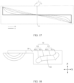
- FIG. 17 is a schematic diagram of shape deformation of the first sliding groove 11 shown in FIG. 7 .
- a line E1 is a reference line of a shape of the first sliding groove 11, and a line F1 is a limit line of the shape of the first sliding groove 11.
- the shape of the first sliding groove 11 may be designed within a range of the line E1 and the line F1 (including the line F1), which is not strictly limited.
- the second sliding groove 51 includes a third segment 511 and a fourth segment 512.
- the third segment 511 includes a third acceleration segment 513 and a third gentle speed segment 514.
- the third acceleration segment 513 and the third gentle speed segment 514 are in a bending connection.
- the bending connection may be understood as that there is an included angle between the third acceleration segment 513 and the third gentle speed segment 514, and the included angle may be within an angle range of 0° to 180°.
- An absolute value of a slope of the third acceleration segment 513 is greater than an absolute value of a slope of the third gentle speed segment 514.
- That the absolute value of a slope of the third acceleration segment 513 is greater than an absolute value of a slope of the third gentle speed segment 514 may be understood that an absolute value of a slope at any position of the third acceleration segment 513 is greater than an absolute value of a slope at any position of the third gentle speed segment 514.
- a coordinate system is established with a first direction X as an abscissa x axis and a second direction Z as an ordinate.
- a flexible display 210 may be parallel to the x axis when the foldable assembly 100 is in the unfolded state.
- the slope of the third acceleration segment 513 indicates a degree of inclination of the third acceleration segment 513 relative to the x axis (the first direction X) when the foldable assembly 100 is in the unfolded state.
- a slope of a curve or straight line corresponding to the third acceleration segment 513 is positive or negative, and the absolute value of the slope of the third acceleration segment 513 is a positive value.
- the slope of the third gentle speed segment 514 indicates a degree of inclination of the third gentle speed segment 514 relative to the x axis (the first direction X) when the foldable assembly 100 is in the unfolded state.
- a slope of a curve or straight line corresponding to the third gentle speed segment 514 is positive or negative, and the absolute value of the slope of the third gentle speed segment 514 is a positive value.
- the third acceleration segment 513 and the third gentle speed segment 514 may be located in a first quadrant of the coordinate system.
- the slope of the third acceleration segment 513 is a positive value
- the slope of the third gentle speed segment 514 is a positive value.
- the absolute value of the slope of the third acceleration segment 513 is greater than the absolute value of the slope of the third gentle speed segment 514.
- the second shaft 22 can slide in the third acceleration segment 513 and the third gentle speed segment 514.
- a sliding speed of the second shaft 22 in the third acceleration segment 513 and a sliding speed of the second shaft 22 in the third gentle speed segment 514 are related to the absolute value of the slope of the third acceleration segment 513 and the absolute value of the slope of the third gentle speed segment 514. Specifically, when the second shaft 22 moves in a segment with a relatively large absolute value of a slope, a movement speed of the second shaft 22 in the segment is relatively fast, and an included angle between the first main swing arm 10 and the second main swing arm 50 may be changed relatively fast.
- the fourth segment 512 includes a fourth acceleration segment 516 and a fourth gentle speed segment 515.
- the fourth gentle speed segment 515 is connected to the third gentle speed segment 514.
- An end, away from the third gentle speed segment 514, of the fourth gentle speed segment 515 and the fourth acceleration segment 516 are in a bending connection.
- the bending connection may be understood as that there is an included angle between the fourth acceleration segment 516 and the fourth gentle speed segment 515, and the included angle may be within a range of 0° to 180°.
- An absolute value of a slope of the fourth acceleration segment 516 is greater than an absolute value of a slope of the fourth gentle speed segment 515.
- That the absolute value of a slope of the fourth acceleration segment 516 is greater than an absolute value of a slope of the fourth gentle speed segment 515 may be understood that an absolute value of a slope at any position of the fourth acceleration segment 516 is greater than an absolute value of a slope at any position of the fourth gentle speed segment 515.
- a coordinate system is established with a first direction X as an abscissa x axis and a second direction Z as an ordinate.
- a flexible display 210 may be parallel to the x axis when the foldable assembly 100 is in the unfolded state.
- the slope of the fourth acceleration segment 516 indicates a degree of inclination of the fourth acceleration segment 516 relative to the x axis (the first direction X) when the foldable assembly 100 is in the unfolded state.
- a slope of a curve or straight line corresponding to the fourth acceleration segment 516 is positive or negative, and the absolute value of the slope of the fourth acceleration segment 516 is a positive value.
- the slope of the fourth gentle speed segment 515 indicates a degree of inclination of the fourth gentle speed segment 515 relative to the x axis (the first direction X) when the foldable assembly 100 is in the unfolded state.
- a slope of a curve or straight line corresponding to the fourth gentle speed segment 515 is positive or negative, and the absolute value of the slope of the fourth gentle speed segment 515 is a positive value.
- the fourth acceleration segment 516 and the fourth gentle speed segment 515 may be located in a third quadrant of the coordinate system.
- the slope of the fourth acceleration segment 516 is a positive value, and the slope of the fourth gentle speed segment 515 is a negative value.
- the absolute value of the slope of the fourth acceleration segment 516 is greater than the absolute value of the slope of the fourth gentle speed segment 515.
- the second shaft 22 can slide in the fourth gentle speed segment 515 and the fourth acceleration segment 516, and a sliding speed of the second shaft 22 in the fourth acceleration segment 516 and a sliding speed of the second shaft 22 in the fourth gentle speed segment 515 are related to the absolute value of the slope of the fourth acceleration segment 516 and the absolute value of the slope of the fourth gentle speed segment 515.
- a movement speed of the second shaft 22 in the segment is relatively fast. Therefore, in this stage, an included angle between the first main swing arm 10 and the second main swing arm 50 may be changed relatively fast.
- the fourth gentle speed segment 515 and the third gentle speed segment 514 are rotationally symmetrical. That is, the third gentle speed segment 514 can be rotated around a fixed point to be changed into the fourth gentle speed segment 515, and the fourth gentle speed segment 515 can be rotated around the same fixed point to be changed into the third gentle speed segment 514.
- an angle at which the third gentle speed segment 514 is rotated to be changed into the fourth gentle speed segment 515 or an angle at which the fourth gentle speed segment 515 is rotated to be changed into the third gentle speed segment 514 is not strictly limited, and the angle may be any angle, for example, 170° or 180°, on the basis of meeting working requirements of the foldable assembly 100.
- the third gentle speed segment 514 may be rotated around a midpoint of a line O2 to be changed into the fourth gentle speed segment 515.
- an absolute value of a slope at a joint of the third gentle speed segment 514 and the fourth gentle speed segment 515 changes slightly.
- a slight change of the absolute value of the slope can enable a speed at which the second shaft 22 moves from an end of the third gentle speed segment 514 to a start of the fourth gentle speed segment 515 to change slightly, and further enable a speed at which the first shaft 21 moves from the third gentle speed segment to the fourth gentle speed segment 515 to change slightly.
- FIG. 18 is a schematic diagram of a structure of the second sliding groove 51 of the foldable assembly 100 shown in FIG. 7 .
- FIG. 19 is a schematic diagram of another structure of the second sliding groove 51 of the foldable assembly 100 shown in FIG. 7 .
- degrees of inclination of a third acceleration segment 513 relative to a first direction X are different.
- a fourth gentle speed segment 515 and a third gentle speed segment 514 are both straight line segments. Based on such disposing, the third gentle speed segment 514 and the fourth gentle speed segment 515 can jointly form a straight line segment shape or a broken line segment shape based on a difference between a rotational angle of the third gentle speed segment 514 and a rotational angle of the fourth gentle speed segment 515. Such disposing is flexible.
- FIG. 20 is a schematic diagram of still another structure of the second sliding groove 51 of the foldable assembly 100 shown in FIG. 7 .
- FIG. 21 is a schematic diagram of yet another structure of the second sliding groove 51 of the foldable assembly 100 shown in FIG. 7 .
- degrees of inclination of a third acceleration segment 513 relative to a first direction X are different.
- both the fourth gentle speed segment 515 and the third gentle speed segment 514 are arc segments, and a center of curvature of the third gentle speed segment 514 and a center of curvature of the fourth gentle speed segment 515 are located on two sides of the second sliding groove 51 respectively.
- the center of curvature of the third gentle speed segment 514 and a center of curvature of the fourth gentle speed segment 515 are located on two sides of the second sliding groove 51 respectively may be understood as that the center of curvature of the third gentle speed segment 514 and the center of curvature of the fourth gentle speed segment 515 are located on one side of the second sliding groove 51 and an opposite side of the second sliding groove 51 respectively with the second sliding groove 51 as a reference object.
- the third gentle speed segment 514 and the fourth gentle speed segment 515 can jointly form a curve segment of a different shape (for example, a wave shape or an S shape) based on a difference between a rotational angle of the third gentle speed segment 514 and a rotational angle of the fourth gentle speed segment 515.
- Such disposing is flexible.
- FIG. 22 is a diagram of a correspondence between a climbing path of a fourth cam structure 832 and a moving path of a second shaft 22 shown in FIG. 7 .
- a stage in which the second shaft 22 slides in a third acceleration segment 513 is a sliding stage S4.
- a stage in which the second shaft 22 slides in a third gentle speed segment 514 and a fourth gentle speed segment 515 is a sliding stage S5.
- a stage in which the second shaft 22 slides in a fourth acceleration segment 516 is a sliding stage S6.
- a critical limit is a second peak value K2.
- a value less than the second peak value K2 indicates that the damping force provided by the second elastic member 85 is less than the gravity required for the first torsion swing arm 30 and the second torsion swing arm to rotate freely.
- a value greater than the second peak value K2 indicates that the damping force provided by the second elastic member 85 is greater than the gravity required for the first torsion swing arm 30 and the second torsion swing arm to rotate freely.
- a stage in which the fourth cam structure 832 climbs along the third cam structure 82 from a left start position to the second peak value K2 is a climbing stage D4.
- a stage in which the fourth cam structure 832 continues to climb above the second peak value K2 along the third cam structure 82 is a climbing stage D5.
- a stage in which the fourth cam structure 832 climbs to a right end position below the second peak value K2 along the third cam structure 82 is a climbing stage D6.
- damping forces provided by the second elastic member 85 are respectively less than, greater than, and less than the gravity required for the first torsion swing arm 30 and the second torsion swing arm to rotate freely.
- a damping assembly 80 is in a first resistance state, a second resistance state, and a third resistance state respectively.
- the fourth cam structure 832 moves in the climbing stage D4.
- the fourth cam structure 832 moves in the climbing stage D5.
- the first sliding end moves in the climbing stage D6. That is, the sliding stage S4 is corresponding to the climbing stage D4, the sliding stage S5 is corresponding to the climbing stage D5, and the sliding stage S6 is corresponding to the climbing stage D6.
- the damping force provided by the second elastic member 85 rapidly increases and approaches the second peak value K2.
- the damping force provided by the second elastic member 85 is greater than the second peak value K2, and the foldable assembly 100 enters a hovering stage.
- a speed of the second shaft 22 in the sliding stage S5 is slower than a speed of the second shaft 22 in the sliding stage S4, so that the damping force provided by the second elastic member 85 is continuously reduced.
- a stage in which the second shaft 22 moves in the third acceleration segment 513 is an acceleration stage in which a damping force provided by the second elastic member 85 rapidly approaches the second peak value K2
- a stage in which the second shaft 22 moves in the third gentle speed segment 514 and the fourth gentle speed segment 515 is a slow speed stage in which the damping force provided by the second elastic member 85 is greater than the second peak value K2, so that the foldable assembly 100 is in a hovering state
- a stage in which the second shaft 22 moves in the fourth acceleration segment 516 is an acceleration stage in which the damping force provided by the second elastic member 85 is less than the second peak value K2, so that the foldable assembly 100 is rapidly unfolded or folded.
- the damping assembly 80 when the foldable assembly 100 is in an unfolded state, the damping assembly 80 is in the first resistance state, the second shaft 22 slides in the third acceleration segment 513, and the first torsion swing arm 30 and the second torsion swing arm 60 are unfolded relative to each other.
- the damping assembly 80 is in the second resistance state, the second shaft 22 slides in the third gentle speed segment 514 and the fourth gentle speed segment 515, and the first torsion swing arm 30 and the second torsion swing arm 60 gradually approach each other.
- the damping assembly 80 is in the third resistance state, the second shaft 22 slides in the fourth acceleration segment 516, and the first torsion swing arm 30 and the second torsion swing arm 60 are folded relative to each other.
- a rotation and folding trajectory of the second torsion swing arm 60 can be effectively defined, a rotation effect of the foldable assembly 100 can be ensured.
- a hand feeling of unfolding and folding the foldable assembly 100 in place can be ensured while a climbing feature of a cam is kept. Therefore, a stage in which the damping force provided by the second elastic member 85 is greater than the second peak value K2 may be prolonged as much as possible during rotation of the second torsion swing arm 60.
- a range of a rotational angle of the foldable assembly 100 corresponding to the first gentle speed segment 114 and the second gentle speed segment 115 may be large, and a range of a rotational angle of the foldable assembly 100 corresponding to the first acceleration segment 113 and the second acceleration segment 116 may be small, effectively prolonging a stage in which the foldable assembly 100 is hovered with the greatest damping.
- the third acceleration segment 513 and the fourth acceleration segment 516 may be rotationally symmetrical. That is, the third acceleration segment 513 can be rotated around a fixed point to be changed into the fourth acceleration segment 516, and the fourth acceleration segment 516 can be rotated around the same fixed point to be changed into the third acceleration segment 513.
- an angle at which the third acceleration segment 513 is rotated to be changed into the fourth acceleration segment 516 or an angle at which the fourth acceleration segment 516 is rotated to be changed into the third acceleration segment 513 is not strictly limited, and the angle may be any angle, for example, 170° or 180°, on the basis of meeting working requirements of the foldable assembly 100.
- the third segment 511 and the fourth segment 512 may be rotationally symmetrical.
- the third segment 511 can be rotated around a fixed point to be changed into the fourth segment 512
- the fourth segment 512 can be rotated around the same fixed point to be changed into the third segment 511.
- a slight change of the absolute value of the slope can enable a speed at which the second shaft 22 moves from an end of the third segment 511 to a start of the fourth segment 512 to change slightly, helping to prolong the sliding stage S2, and further prolonging the stage in which the foldable assembly 100 may be hovered.
- a range of an angle at which the foldable assembly 100 may be hovered may be further expanded, helping to implement hovering of the foldable assembly 100 at a large angle.
- a range of an angle at which a foldable assembly is hovered in conventional technologies is 80° to 120°
- a range of an angle at which the foldable assembly 100 is hovered in the technical solution of this application may be 30° to 150°.
- the second shaft 22 passes the third acceleration segment 513, the third gentle speed segment 514, the fourth gentle speed segment 515, and the fourth acceleration segment 516 in sequence. It may be known that, based on a change of an absolute value of a slope of the third acceleration segment 513 and a change of an absolute value of a slope of the third gentle speed segment 514 in the third segment 511, a speed of the second shaft 22 in the third segment 511 is fast first and then slow. It may be known that, based on the change of an absolute value of a slope of the fourth gentle speed segment 515 and an absolute value of a slope of the fourth acceleration segment 516 in the fourth segment 512, a speed of the second shaft 22 in the fourth segment 512 is slow first and then fast.
- the movement speed of the second shaft 22 is related to the damping force provided by the second elastic member 85.
- the damping force provided by the second elastic member 85 is greater than the second peak value K2, and the foldable assembly 100 enters a hovering stage.
- the damping force provided by the second elastic member 85 is less than the second peak value K2, and the foldable assembly 100 is unfolded or folded.
- an angle at which the third segment 511 is rotated to be changed into the fourth segment 512 or an angle at which the fourth segment 512 is rotated to be changed into the third segment 511 is not strictly limited, and the angle may be any angle, for example, 170° or 180°, on the basis of meeting working requirements of the foldable assembly 100.
- the third segment 511 may be rotated around a midpoint of a line O2 to be changed into the fourth segment 512.
- the third acceleration segment 513 and the fourth acceleration segment 516 are both straight line segments.
- the third gentle speed segment 514 and the fourth gentle speed segment 515 may be straight line segments, so that the second sliding groove 51 presents a broken line shape as a whole that includes only straight line segments.
- the third gentle speed segment 514 and the fourth gentle speed segment 515 may be arc segments, so that the second sliding groove 51 presents a curve shape as a whole in which an arc segment and a straight line segment are mixed.
- both the third acceleration segment 513 and the fourth acceleration segment 516 are arc segments, and a center of curvature of the third acceleration segment 513 and a center of curvature of the fourth acceleration segment 516 are located on two sides of the second sliding groove 51 respectively. That the center of curvature of the third acceleration segment 513 and a center of curvature of the fourth acceleration segment 516 are located on two sides of the second sliding groove 51 respectively may be understood as that the center of curvature of the third acceleration segment 513 and the center of curvature of the fourth acceleration segment 516 are located on one side of the second sliding groove 51 and an opposite side of the second sliding groove 51 respectively with the second sliding groove 51 as a reference object.
- center of curvature of the third acceleration segment 513 and the center of curvature of the third gentle speed segment 514 are located on a same side of the second sliding groove 51
- center of curvature of the fourth acceleration segment 516 and the center of curvature of the fourth gentle speed segment 515 are located on a same side of the second sliding groove 51.
- the third gentle speed segment 514 and the fourth gentle speed segment 515 may be straight line segments, so that the second sliding groove 51 presents a curve shape as a whole in which an arc segment and a straight line segment are mixed.
- the third gentle speed segment 514 and the fourth gentle speed segment 515 may be arc segments, so that the second sliding groove 51 presents a curve shape as a whole that includes only arc segments.
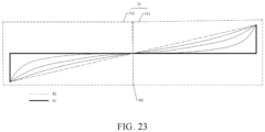
- FIG. 23 is a schematic diagram of shape deformation of the second sliding groove 51 shown in FIG. 7 .
- a line E2 is a reference line of a shape of the second sliding groove 51
- a line F2 is a limit line of the shape of the second sliding groove 51.
Landscapes
- Engineering & Computer Science (AREA)
- Computer Hardware Design (AREA)
- Theoretical Computer Science (AREA)
- Human Computer Interaction (AREA)
- Physics & Mathematics (AREA)
- General Engineering & Computer Science (AREA)
- General Physics & Mathematics (AREA)
- Signal Processing (AREA)
- Telephone Set Structure (AREA)
Claims (13)
- Eine faltbare Baugruppe (100), umfassend:einen ersten Hauptschwenkarm (10), wobei der erste Hauptschwenkarm (10) mit einer ersten Gleitnut (11) versehen ist, die erste Gleitnut (11) einen ersten Beschleunigungsabschnitt (113) und einen ersten sanften Geschwindigkeitsabschnitt (114) umfasst, die miteinander verbunden sind, und der Absolutwert der Neigung des ersten Beschleunigungsabschnitts (113) größer ist als der Absolutwert der Neigung des ersten sanften Geschwindigkeitsabschnitts (114);einen ersten Torsionsschwenkarm (30), wobei der erste Torsionsschwenkarm (30) ein erstes Ende (31) und ein zweites Ende (32) umfasst;eine erste Welle (21), wobei die erste Welle (21) durch das erste Ende (31) und die erste Gleitnut (11) verläuft und den ersten Torsionsschwenkarm (30) und den ersten Hauptschwenkarm (10) verbindet; undeine Dämpfungsbaugruppe (80), wobei die Dämpfungsbaugruppe (80) mit dem zweiten Ende (32) verbunden ist, und wobei die Dämpfungsbaugruppe (80) und die erste Welle (21) so konfiguriert sind, dass, wenn der erste Torsionsschwenkarm (30) relativ zur Dämpfungsbaugruppe (80) rotiert, die erste Welle sich vom ersten Beschleunigungsabschnitt (113) zum ersten sanften Geschwindigkeitsabschnitt (114) bewegt, die Dämpfungsbaugruppe (80) von einem ersten Widerstandszustand in einen zweiten Widerstandszustand übergeht und der Rotationswiderstand der Dämpfungsbaugruppe (80) im zweiten Widerstandszustand gegenüber dem ersten Torsionsschwenkarm (30) größer ist als der Rotationswiderstand der Dämpfungsbaugruppe (80) im ersten Widerstandszustand gegenüber dem ersten Torsionsschwenkarm (30).
- Die faltbare Baugruppe (100) gemäß Anspruch 1, wobei die erste Gleitnut (11) ferner einen zweiten sanften Geschwindigkeitsabschnitt (115) und einen zweiten Beschleunigungsabschnitt (116) umfasst, ein Ende des zweiten sanften Geschwindigkeitsabschnitts (115) mit dem ersten sanften Geschwindigkeitsabschnitt (114) verbunden ist, das andere Ende des zweiten sanften Geschwindigkeitsabschnitts (115) mit dem zweiten Beschleunigungsabschnitt (116) verbunden ist, der Absolutwert der Neigung des zweiten Beschleunigungsabschnitts (116) größer ist als der Absolutwert der Neigung des zweiten sanften Geschwindigkeitsabschnitts (115), und der zweite sanfte Geschwindigkeitsabschnitt (115) und der erste sanfte Geschwindigkeitsabschnitt (114) rotationssymmetrisch sind; und
wobei die Dämpfungsanordnung (80) und die erste Welle (21) weiterhin so konfiguriert sind, dass, wenn sich die erste Welle vom ersten sanften Geschwindigkeitsabschnitt (114) zum zweiten sanften Geschwindigkeitsabschnitt (115) bewegt, die Dämpfungsanordnung (80) den zweiten Widerstandszustand beibehält, die erste Welle sich vom zweiten sanften Geschwindigkeitsabschnitt (115) zum zweiten Beschleunigungsabschnitt (116) bewegt, die Dämpfungsanordnung (80) vom zweiten Widerstandszustand in einen dritten Widerstandszustand wechselt, und der Rotationswiderstand der Dämpfungsanordnung (80) im zweiten Widerstandszustand gegenüber dem ersten Torsionsschwingarm (30) größer ist als der Rotationswiderstand der Dämpfungsanordnung (80) im dritten Widerstandszustand gegenüber dem ersten Torsionsschwingarm (30). - Die faltbare Anordnung (100) nach Anspruch 2, wobei sich ein Krümmungsmittelpunkt des ersten Beschleunigungsabschnitts (113) und ein Krümmungsmittelpunkt des zweiten Beschleunigungsabschnitts (116) jeweils auf zwei Seiten der ersten Gleitnut (11) befinden.
- Die faltbare Anordnung (100) nach Anspruch 2, wobei der erste Beschleunigungsabschnitt (113) und der zweite Beschleunigungsabschnitt (116) beide gerade Linienabschnitte sind.
- Die faltbare Anordnung (100) nach einem der Ansprüche 2 bis 4, wobei der erste Beschleunigungsabschnitt (113) und der zweite Beschleunigungsabschnitt (116) rotationssymmetrisch sind.
- Die faltbare Anordnung (100) nach einem der Ansprüche 2 bis 5, wobei sich ein Krümmungsmittelpunkt des ersten sanften Geschwindigkeitsabschnitts (114) und ein Krümmungsmittelpunkt des zweiten sanften Geschwindigkeitsabschnitts (115) jeweils auf zwei Seiten der ersten Gleitnut (11) befinden.
- Die faltbare Anordnung (100) nach Anspruch 6, wobei sich der Krümmungsmittelpunkt des ersten sanften Geschwindigkeitsabschnitts (114) und der Krümmungsmittelpunkt des ersten Beschleunigungsabschnitts (113) auf derselben Seite der ersten Gleitnut (11) befinden, und der Krümmungsmittelpunkt des zweiten sanften Geschwindigkeitsabschnitts (115) und der Krümmungsmittelpunkt des zweiten Beschleunigungsabschnitts (116) auf derselben Seite der ersten Gleitnut (11) liegen.
- Die faltbare Anordnung (100) nach Anspruch 6, wobei der erste sanfte Geschwindigkeitsabschnitt (114) und der zweite sanfte Geschwindigkeitsabschnitt (115) beide gerade Linienabschnitte sind.
- Die faltbare Anordnung (100) nach einem der Ansprüche 1 bis 8, wobei die faltbare Anordnung (100) weiterhin eine erste Drehwelle (41) umfasst, die erste Drehwelle (41) durch das zweite Ende (32) hindurchgeht, und die Dämpfungsanordnung (80) eine erste Nockenstruktur (81), eine zweite Nockenstruktur (831), ein erstes elastisches Element (84) und ein Begrenzungselement (86) umfasst; und
Die erste Nockenstruktur (81) ist am zweiten Ende (32) befestigt und auf die erste Drehwelle (41) aufgesteckt, die zweite Nockenstruktur (831) ist auf die erste Drehwelle (41) aufgesteckt und steht in Kontakt mit der ersten Nockenstruktur (81), das Begrenzungselement (86) ist an der ersten Drehwelle (41) befestigt, das erste elastische Element stützt sich zwischen der zweiten Nockenstruktur (831) und dem Begrenzungselement (86) ab, und die zweite Nockenstruktur (831) kann sich entlang der ersten Drehwelle (41) bewegen, wenn sie von der ersten Nockenstruktur (81) gedrückt wird, um das erste elastische Element (84) zu komprimieren oder freizugeben. - Eine faltbare Baugruppe (100), umfassend:einen ersten Hauptschwenkarm (10), wobei der erste Hauptschwenkarm (10) mit einer ersten Gleitnut (11) versehen ist, die erste Gleitnut (11) umfasst einen ersten Beschleunigungsabschnitt (113) und einen ersten sanften Geschwindigkeitsabschnitt (114), die miteinander verbunden sind, und der Absolutwert der Neigung des ersten Beschleunigungsabschnitts (113) größer ist als der Absolutwert der Neigung des ersten sanften Geschwindigkeitsabschnitts (114);einen ersten Torsionsschwenkarm (30), wobei der erste Torsionsschwenkarm (30) ein erstes Ende (31) und ein zweites Ende (32) umfasst;eine erste Welle (21), wobei die erste Welle (21) durch das erste Ende (31) und die erste Gleitnut (11) verläuft, die erste Welle (21) den ersten Torsionsschwenkarm (30) und den ersten Hauptschwenkarm (10) verbindet, und die erste Welle (21) in der ersten Gleitnut (11) gleiten kann;eine erste Drehwelle (41), wobei die erste Drehwelle (41) durch das zweite Ende (32) verläuft; undeine Dämpfungsbaugruppe (80), wobei die Dämpfungsbaugruppe (80) eine erste Nockenstruktur (81), eine zweite Nockenstruktur (831), ein erstes elastisches Element (84) und ein Begrenzungselement (86) umfasst, die erste Nockenstruktur (81) am zweiten Ende (32) befestigt und auf die erste Drehwelle (41) aufgesteckt ist, die zweite Nockenstruktur (831) auf die erste Drehwelle (41) aufgesteckt ist und mit der ersten Nockenstruktur (81) in Kontakt steht, das erste elastische Element sich zwischen der zweiten Nockenstruktur (831) und dem Begrenzungselement (86) abstützt, und die zweite Nockenstruktur (831) sich entlang der ersten Drehwelle (41) bewegen kann, wenn sie von der ersten Nockenstruktur (81) gedrückt wird, um das erste elastische Element (84) zu komprimieren oder freizugeben.
- Die faltbare Baugruppe (100) nach Anspruch 10, wobei die erste Gleitnut (11) ferner einen zweiten sanften Geschwindigkeitsabschnitt (115) und einen zweiten Beschleunigungsabschnitt (116) umfasst, wobei ein Ende des zweiten sanften Geschwindigkeitsabschnitts (115) mit dem ersten sanften Geschwindigkeitsabschnitt (114) verbunden ist, das andere Ende des zweiten sanften Geschwindigkeitsabschnitts (115) mit dem zweiten Beschleunigungsabschnitt (116) verbunden ist, eine Neigung des zweiten Beschleunigungsabschnitts (116) größer ist als eine Neigung des zweiten sanften Geschwindigkeitsabschnitts (115), und der zweite sanfte Geschwindigkeitsabschnitt (115) und der erste sanfte Geschwindigkeitsabschnitt (114) rotationssymmetrisch sind.
- Die faltbare Baugruppe (100) nach Anspruch 11, wobei ein Krümmungsmittelpunkt des ersten Beschleunigungsabschnitts (113) und ein Krümmungsmittelpunkt des zweiten Beschleunigungsabschnitts (116) sich jeweils auf zwei Seiten der ersten Gleitnut (11) befinden.
- Eine elektronische Vorrichtung (200), umfassend ein flexibles Display (210) und eine faltbare Baugruppe (100) nach einem der Ansprüche 1 bis 9, wobei das flexible Display (210) auf der faltbaren Baugruppe (100) angeordnet ist; oder
umfassend ein flexibles Display (210) und eine faltbare Baugruppe (100) nach einem der Ansprüche 10 bis 12, wobei das flexible Display (210) auf der faltbaren Baugruppe (100) angeordnet ist.
Applications Claiming Priority (3)
| Application Number | Priority Date | Filing Date | Title |
|---|---|---|---|
| CN202210021087 | 2022-01-10 | ||
| CN202210437862.5A CN116447215B (zh) | 2022-01-10 | 2022-04-25 | 折叠组件及电子设备 |
| PCT/CN2022/143268 WO2023131041A1 (zh) | 2022-01-10 | 2022-12-29 | 折叠组件及电子设备 |
Publications (3)
| Publication Number | Publication Date |
|---|---|
| EP4269825A1 EP4269825A1 (de) | 2023-11-01 |
| EP4269825A4 EP4269825A4 (de) | 2024-08-21 |
| EP4269825B1 true EP4269825B1 (de) | 2025-03-19 |
Family
ID=87073153
Family Applications (1)
| Application Number | Title | Priority Date | Filing Date |
|---|---|---|---|
| EP22918482.5A Active EP4269825B1 (de) | 2022-01-10 | 2022-12-29 | Faltanordnung und elektronische vorrichtung |
Country Status (3)
| Country | Link |
|---|---|
| US (1) | US12504792B2 (de) |
| EP (1) | EP4269825B1 (de) |
| WO (1) | WO2023131041A1 (de) |
Cited By (2)
| Publication number | Priority date | Publication date | Assignee | Title |
|---|---|---|---|---|
| CN116447215A (zh) * | 2022-01-10 | 2023-07-18 | 荣耀终端有限公司 | 折叠组件及电子设备 |
| US12504792B2 (en) | 2022-01-10 | 2025-12-23 | Honor Device Co., Ltd. | Foldable assembly and electronic device |
Family Cites Families (41)
| Publication number | Priority date | Publication date | Assignee | Title |
|---|---|---|---|---|
| US8971031B2 (en) * | 2012-08-07 | 2015-03-03 | Creator Technology B.V. | Display system with a flexible display |
| KR101875855B1 (ko) * | 2014-02-17 | 2018-07-06 | 삼성전자주식회사 | 힌지장치 및 이를 구비하는 폴더블 디스플레이 장치 |
| KR102233119B1 (ko) * | 2014-09-23 | 2021-03-30 | 삼성디스플레이 주식회사 | 표시장치 |
| KR102322377B1 (ko) * | 2014-12-31 | 2021-11-05 | 엘지디스플레이 주식회사 | 접이식 디스플레이 장치 |
| KR20160107940A (ko) * | 2015-03-06 | 2016-09-19 | (주)제이엠씨 | 단일면 폴딩장치 |
| BR102016011179A2 (pt) * | 2015-05-18 | 2018-07-17 | Atasan Metal Sanayi Ve Ticaret Limited Sirketi | mecanismo de articulação |
| US9848502B1 (en) * | 2017-03-24 | 2017-12-19 | Shin Zu Shing Co., Ltd. | Hinge assembly and foldable display device using the same |
| KR102426694B1 (ko) * | 2017-05-02 | 2022-07-29 | 삼성전자주식회사 | 플렉서블 디스플레이를 포함하는 전자 장치 |
| CN207977988U (zh) * | 2018-01-08 | 2018-10-16 | 杭州安费诺飞凤通信部品有限公司 | 一种内折柔性屏移动终端铰链及内折柔性屏移动终端 |
| CN208421695U (zh) * | 2018-07-13 | 2019-01-22 | Oppo广东移动通信有限公司 | 电子设备 |
| JP2020063749A (ja) * | 2018-10-15 | 2020-04-23 | 日本電産サンキョー株式会社 | ダンパ付きヒンジ |
| CN111698355B (zh) * | 2019-03-15 | 2021-07-09 | 华为技术有限公司 | 一种转轴机构及移动终端 |
| CN112087540B (zh) * | 2019-06-14 | 2021-10-22 | 北京小米移动软件有限公司 | 折叠装置、显示屏模块及移动终端 |
| US12101420B2 (en) * | 2019-07-08 | 2024-09-24 | Lg Electronics Inc. | Mobile terminal |
| TWI695666B (zh) * | 2019-07-09 | 2020-06-01 | 富世達股份有限公司 | 樞轉機構及可撓式電子裝置 |
| CN114374757B (zh) * | 2019-08-30 | 2025-07-15 | Oppo广东移动通信有限公司 | 电子设备及折叠组件 |
| CN211239890U (zh) * | 2019-10-12 | 2020-08-11 | 杭州安费诺飞凤通信部品有限公司 | 一种应用于内折柔性屏终端的铰链及内折柔性屏终端 |
| KR102689031B1 (ko) * | 2019-10-21 | 2024-07-29 | 삼성전자주식회사 | 방진 구조를 포함하는 전자 장치 |
| KR102668216B1 (ko) * | 2019-12-02 | 2024-05-23 | 삼성전자주식회사 | 힌지 조립체를 포함하는 폴더블 전자 장치 |
| KR102641514B1 (ko) * | 2020-02-10 | 2024-02-27 | 삼성전자주식회사 | 힌지 조립체를 포함하는 폴더블 전자 장치 |
| CN213270695U (zh) * | 2020-05-12 | 2021-05-25 | 杭州安费诺飞凤通信部品有限公司 | 一种应用于内折柔性屏终端的运动机构 |
| CN212840395U (zh) | 2020-08-07 | 2021-03-30 | 新日兴股份有限公司 | 枢纽器与使用其的电子装置 |
| US11615720B2 (en) * | 2020-08-26 | 2023-03-28 | Samsung Display Co., Ltd. | Display device |
| CN112901643B (zh) * | 2020-09-14 | 2022-05-24 | 华为技术有限公司 | 折叠装置及电子设备 |
| CN112178041A (zh) | 2020-09-16 | 2021-01-05 | 珠海格力电器股份有限公司 | 一种阻尼机构、折叠铰链及电子装置 |
| KR102311588B1 (ko) * | 2020-10-20 | 2021-10-13 | 주식회사 이음 | 폴더블 디스플레이 장치 |
| CN116635639A (zh) * | 2020-11-18 | 2023-08-22 | 三星电子株式会社 | 包括扭矩结构的电子设备 |
| KR102873610B1 (ko) * | 2021-01-28 | 2025-10-21 | 삼성전자주식회사 | 암부와 회전부의 개선된 결합 구조를 가지는 힌지 구조 및 이를 포함하는 전자 장치 |
| TWI767591B (zh) * | 2021-03-03 | 2022-06-11 | 富世達股份有限公司 | 鉸鏈 |
| CN113257136A (zh) * | 2021-06-03 | 2021-08-13 | 武汉华星光电半导体显示技术有限公司 | 折叠显示装置 |
| CN113315860B (zh) * | 2021-06-11 | 2024-09-20 | 维沃移动通信有限公司 | 折叠机构及电子设备 |
| CN113643612B (zh) | 2021-07-20 | 2023-01-24 | 江苏盈智融科技有限公司 | 内折齿轮连杆式柔性屏转轴机构 |
| CN115022426B (zh) * | 2021-09-26 | 2023-04-07 | 荣耀终端有限公司 | 一种转动机构、支撑装置和折叠屏终端 |
| US11522985B1 (en) * | 2021-09-30 | 2022-12-06 | Motorola Mobility Llc | Hinged electronic device with displacement altering hinge and corresponding systems |
| KR20230097763A (ko) * | 2021-12-24 | 2023-07-03 | 엘지디스플레이 주식회사 | 폴더블 표시 장치 |
| EP4269825B1 (de) | 2022-01-10 | 2025-03-19 | Honor Device Co., Ltd. | Faltanordnung und elektronische vorrichtung |
| CN116557406A (zh) * | 2022-01-30 | 2023-08-08 | 华为技术有限公司 | 一种转轴机构及电子设备 |
| TWI805243B (zh) * | 2022-02-25 | 2023-06-11 | 富世達股份有限公司 | 鉸鏈的同動模組 |
| US11917780B2 (en) * | 2022-03-08 | 2024-02-27 | Microsoft Technology Licensing, Llc | Hinged device with a flexible display |
| TWM631213U (zh) * | 2022-05-12 | 2022-08-21 | 鑫禾科技股份有限公司 | 樞轉裝置 |
| TWI852444B (zh) * | 2023-03-28 | 2024-08-11 | 富世達股份有限公司 | 多連桿式鉸鏈 |
-
2022
- 2022-12-29 EP EP22918482.5A patent/EP4269825B1/de active Active
- 2022-12-29 US US18/263,975 patent/US12504792B2/en active Active
- 2022-12-29 WO PCT/CN2022/143268 patent/WO2023131041A1/zh not_active Ceased
Cited By (3)
| Publication number | Priority date | Publication date | Assignee | Title |
|---|---|---|---|---|
| CN116447215A (zh) * | 2022-01-10 | 2023-07-18 | 荣耀终端有限公司 | 折叠组件及电子设备 |
| CN116447215B (zh) * | 2022-01-10 | 2025-07-25 | 荣耀终端股份有限公司 | 折叠组件及电子设备 |
| US12504792B2 (en) | 2022-01-10 | 2025-12-23 | Honor Device Co., Ltd. | Foldable assembly and electronic device |
Also Published As
| Publication number | Publication date |
|---|---|
| WO2023131041A9 (zh) | 2023-09-07 |
| US20240302870A1 (en) | 2024-09-12 |
| US12504792B2 (en) | 2025-12-23 |
| EP4269825A4 (de) | 2024-08-21 |
| WO2023131041A1 (zh) | 2023-07-13 |
| EP4269825A1 (de) | 2023-11-01 |
Similar Documents
| Publication | Publication Date | Title |
|---|---|---|
| US12429924B2 (en) | Hinge, display panel, and electronic device | |
| EP4215767B1 (de) | Klappmechanismus und endgerätevorrichtung | |
| EP4269825B1 (de) | Faltanordnung und elektronische vorrichtung | |
| EP4485908A1 (de) | Drehwellenmechanismus und klappbare vorrichtung | |
| EP4461979B1 (de) | Drehmechanismus und klappbare elektronische vorrichtung | |
| CN112513773A (zh) | 一种框架模组及可弯曲终端 | |
| CN112602141A (zh) | 连接装置及可弯曲设备 | |
| CN112470097A (zh) | 可弯曲显示模组及可弯曲终端 | |
| US12572183B2 (en) | Rotating shaft mechanism and electronic device | |
| CN208431261U (zh) | 联动铰链、连接装置及可弯曲终端 | |
| US20260093294A1 (en) | Synchronization mechanism, rotating shaft mechanism, and electronic device | |
| CN117419098B (zh) | 转动机构和可折叠电子设备 | |
| WO2023001105A1 (zh) | 折叠机构及电子设备 | |
| EP4279755A1 (de) | Drehmechanismus und klappbare elektronische vorrichtung | |
| EP4561036A1 (de) | Drehwellenstruktur und klappendgerät | |
| CN116447215B (zh) | 折叠组件及电子设备 | |
| CN116838702B (zh) | 转动机构和可折叠电子设备 | |
| CN217784008U (zh) | 转动机构及电子设备 | |
| WO2026025826A1 (zh) | 一种折叠装置、显示终端 | |
| EP4560432A1 (de) | Klappmechanismus und elektronische vorrichtung | |
| EP4528117A1 (de) | Drehmechanismus und klappbare elektronische vorrichtung | |
| HK40074004B (en) | Electronic device and folding apparatus | |
| HK40074004A (en) | Electronic device and folding apparatus | |
| CN119222248A (zh) | 一种转轴机构及电子设备 |
Legal Events
| Date | Code | Title | Description |
|---|---|---|---|
| STAA | Information on the status of an ep patent application or granted ep patent |
Free format text: STATUS: THE INTERNATIONAL PUBLICATION HAS BEEN MADE |
|
| PUAI | Public reference made under article 153(3) epc to a published international application that has entered the european phase |
Free format text: ORIGINAL CODE: 0009012 |
|
| STAA | Information on the status of an ep patent application or granted ep patent |
Free format text: STATUS: REQUEST FOR EXAMINATION WAS MADE |
|
| 17P | Request for examination filed |
Effective date: 20230728 |
|
| AK | Designated contracting states |
Kind code of ref document: A1 Designated state(s): AL AT BE BG CH CY CZ DE DK EE ES FI FR GB GR HR HU IE IS IT LI LT LU LV MC ME MK MT NL NO PL PT RO RS SE SI SK SM TR |
|
| REG | Reference to a national code |
Ref country code: DE Ref legal event code: R079 Free format text: PREVIOUS MAIN CLASS: F16C0011120000 Ipc: H04M0001020000 Ref country code: DE Ref legal event code: R079 Ref document number: 602022012080 Country of ref document: DE Free format text: PREVIOUS MAIN CLASS: F16C0011120000 Ipc: H04M0001020000 |
|
| A4 | Supplementary search report drawn up and despatched |
Effective date: 20240722 |
|
| RIC1 | Information provided on ipc code assigned before grant |
Ipc: G06F 1/16 20060101ALI20240716BHEP Ipc: H04M 1/02 20060101AFI20240716BHEP |
|
| GRAP | Despatch of communication of intention to grant a patent |
Free format text: ORIGINAL CODE: EPIDOSNIGR1 |
|
| STAA | Information on the status of an ep patent application or granted ep patent |
Free format text: STATUS: GRANT OF PATENT IS INTENDED |
|
| RIC1 | Information provided on ipc code assigned before grant |
Ipc: G06F 1/16 20060101ALI20241016BHEP Ipc: H04M 1/02 20060101AFI20241016BHEP |
|
| DAV | Request for validation of the european patent (deleted) | ||
| DAX | Request for extension of the european patent (deleted) | ||
| INTG | Intention to grant announced |
Effective date: 20241025 |
|
| GRAS | Grant fee paid |
Free format text: ORIGINAL CODE: EPIDOSNIGR3 |
|
| GRAA | (expected) grant |
Free format text: ORIGINAL CODE: 0009210 |
|
| STAA | Information on the status of an ep patent application or granted ep patent |
Free format text: STATUS: THE PATENT HAS BEEN GRANTED |
|
| AK | Designated contracting states |
Kind code of ref document: B1 Designated state(s): AL AT BE BG CH CY CZ DE DK EE ES FI FR GB GR HR HU IE IS IT LI LT LU LV MC ME MK MT NL NO PL PT RO RS SE SI SK SM TR |
|
| REG | Reference to a national code |
Ref country code: GB Ref legal event code: FG4D |
|
| REG | Reference to a national code |
Ref country code: CH Ref legal event code: EP |
|
| REG | Reference to a national code |
Ref country code: IE Ref legal event code: FG4D |
|
| REG | Reference to a national code |
Ref country code: DE Ref legal event code: R096 Ref document number: 602022012080 Country of ref document: DE |
|
| REG | Reference to a national code |
Ref country code: NL Ref legal event code: FP |
|
| PG25 | Lapsed in a contracting state [announced via postgrant information from national office to epo] |
Ref country code: RS Free format text: LAPSE BECAUSE OF FAILURE TO SUBMIT A TRANSLATION OF THE DESCRIPTION OR TO PAY THE FEE WITHIN THE PRESCRIBED TIME-LIMIT Effective date: 20250619 |
|
| PG25 | Lapsed in a contracting state [announced via postgrant information from national office to epo] |
Ref country code: FI Free format text: LAPSE BECAUSE OF FAILURE TO SUBMIT A TRANSLATION OF THE DESCRIPTION OR TO PAY THE FEE WITHIN THE PRESCRIBED TIME-LIMIT Effective date: 20250319 |
|
| REG | Reference to a national code |
Ref country code: LT Ref legal event code: MG9D |
|
| PG25 | Lapsed in a contracting state [announced via postgrant information from national office to epo] |
Ref country code: NO Free format text: LAPSE BECAUSE OF FAILURE TO SUBMIT A TRANSLATION OF THE DESCRIPTION OR TO PAY THE FEE WITHIN THE PRESCRIBED TIME-LIMIT Effective date: 20250619 |
|
| PG25 | Lapsed in a contracting state [announced via postgrant information from national office to epo] |
Ref country code: HR Free format text: LAPSE BECAUSE OF FAILURE TO SUBMIT A TRANSLATION OF THE DESCRIPTION OR TO PAY THE FEE WITHIN THE PRESCRIBED TIME-LIMIT Effective date: 20250319 |
|
| PG25 | Lapsed in a contracting state [announced via postgrant information from national office to epo] |
Ref country code: LV Free format text: LAPSE BECAUSE OF FAILURE TO SUBMIT A TRANSLATION OF THE DESCRIPTION OR TO PAY THE FEE WITHIN THE PRESCRIBED TIME-LIMIT Effective date: 20250319 |
|
| PG25 | Lapsed in a contracting state [announced via postgrant information from national office to epo] |
Ref country code: GR Free format text: LAPSE BECAUSE OF FAILURE TO SUBMIT A TRANSLATION OF THE DESCRIPTION OR TO PAY THE FEE WITHIN THE PRESCRIBED TIME-LIMIT Effective date: 20250620 Ref country code: BG Free format text: LAPSE BECAUSE OF FAILURE TO SUBMIT A TRANSLATION OF THE DESCRIPTION OR TO PAY THE FEE WITHIN THE PRESCRIBED TIME-LIMIT Effective date: 20250319 |
|
| REG | Reference to a national code |
Ref country code: AT Ref legal event code: MK05 Ref document number: 1777931 Country of ref document: AT Kind code of ref document: T Effective date: 20250319 |
|
| PG25 | Lapsed in a contracting state [announced via postgrant information from national office to epo] |
Ref country code: SE Free format text: LAPSE BECAUSE OF FAILURE TO SUBMIT A TRANSLATION OF THE DESCRIPTION OR TO PAY THE FEE WITHIN THE PRESCRIBED TIME-LIMIT Effective date: 20250319 |
|
| PG25 | Lapsed in a contracting state [announced via postgrant information from national office to epo] |
Ref country code: SM Free format text: LAPSE BECAUSE OF FAILURE TO SUBMIT A TRANSLATION OF THE DESCRIPTION OR TO PAY THE FEE WITHIN THE PRESCRIBED TIME-LIMIT Effective date: 20250319 |
|
| PG25 | Lapsed in a contracting state [announced via postgrant information from national office to epo] |
Ref country code: ES Free format text: LAPSE BECAUSE OF FAILURE TO SUBMIT A TRANSLATION OF THE DESCRIPTION OR TO PAY THE FEE WITHIN THE PRESCRIBED TIME-LIMIT Effective date: 20250319 Ref country code: PT Free format text: LAPSE BECAUSE OF FAILURE TO SUBMIT A TRANSLATION OF THE DESCRIPTION OR TO PAY THE FEE WITHIN THE PRESCRIBED TIME-LIMIT Effective date: 20250721 |
|
| PG25 | Lapsed in a contracting state [announced via postgrant information from national office to epo] |
Ref country code: PL Free format text: LAPSE BECAUSE OF FAILURE TO SUBMIT A TRANSLATION OF THE DESCRIPTION OR TO PAY THE FEE WITHIN THE PRESCRIBED TIME-LIMIT Effective date: 20250319 Ref country code: IT Free format text: LAPSE BECAUSE OF FAILURE TO SUBMIT A TRANSLATION OF THE DESCRIPTION OR TO PAY THE FEE WITHIN THE PRESCRIBED TIME-LIMIT Effective date: 20250319 |
|
| PG25 | Lapsed in a contracting state [announced via postgrant information from national office to epo] |
Ref country code: AT Free format text: LAPSE BECAUSE OF FAILURE TO SUBMIT A TRANSLATION OF THE DESCRIPTION OR TO PAY THE FEE WITHIN THE PRESCRIBED TIME-LIMIT Effective date: 20250319 |
|
| PG25 | Lapsed in a contracting state [announced via postgrant information from national office to epo] |
Ref country code: EE Free format text: LAPSE BECAUSE OF FAILURE TO SUBMIT A TRANSLATION OF THE DESCRIPTION OR TO PAY THE FEE WITHIN THE PRESCRIBED TIME-LIMIT Effective date: 20250319 Ref country code: CZ Free format text: LAPSE BECAUSE OF FAILURE TO SUBMIT A TRANSLATION OF THE DESCRIPTION OR TO PAY THE FEE WITHIN THE PRESCRIBED TIME-LIMIT Effective date: 20250319 |
|
| PG25 | Lapsed in a contracting state [announced via postgrant information from national office to epo] |
Ref country code: RO Free format text: LAPSE BECAUSE OF FAILURE TO SUBMIT A TRANSLATION OF THE DESCRIPTION OR TO PAY THE FEE WITHIN THE PRESCRIBED TIME-LIMIT Effective date: 20250319 |
|
| PG25 | Lapsed in a contracting state [announced via postgrant information from national office to epo] |
Ref country code: SK Free format text: LAPSE BECAUSE OF FAILURE TO SUBMIT A TRANSLATION OF THE DESCRIPTION OR TO PAY THE FEE WITHIN THE PRESCRIBED TIME-LIMIT Effective date: 20250319 |
|
| PG25 | Lapsed in a contracting state [announced via postgrant information from national office to epo] |
Ref country code: IS Free format text: LAPSE BECAUSE OF FAILURE TO SUBMIT A TRANSLATION OF THE DESCRIPTION OR TO PAY THE FEE WITHIN THE PRESCRIBED TIME-LIMIT Effective date: 20250719 |
|
| PGFP | Annual fee paid to national office [announced via postgrant information from national office to epo] |
Ref country code: NL Payment date: 20251112 Year of fee payment: 4 |
|
| REG | Reference to a national code |
Ref country code: DE Ref legal event code: R097 Ref document number: 602022012080 Country of ref document: DE |
|
| PGFP | Annual fee paid to national office [announced via postgrant information from national office to epo] |
Ref country code: DE Payment date: 20251104 Year of fee payment: 4 |
|
| PG25 | Lapsed in a contracting state [announced via postgrant information from national office to epo] |
Ref country code: DK Free format text: LAPSE BECAUSE OF FAILURE TO SUBMIT A TRANSLATION OF THE DESCRIPTION OR TO PAY THE FEE WITHIN THE PRESCRIBED TIME-LIMIT Effective date: 20250319 |
|
| PLBE | No opposition filed within time limit |
Free format text: ORIGINAL CODE: 0009261 |
|
| STAA | Information on the status of an ep patent application or granted ep patent |
Free format text: STATUS: NO OPPOSITION FILED WITHIN TIME LIMIT |
|
| REG | Reference to a national code |
Ref country code: CH Ref legal event code: L10 Free format text: ST27 STATUS EVENT CODE: U-0-0-L10-L00 (AS PROVIDED BY THE NATIONAL OFFICE) Effective date: 20260128 |
|
| 26N | No opposition filed |
Effective date: 20251222 |