EP4216238B1 - Nanoparticules et grains à base de fer - Google Patents
Nanoparticules et grains à base de fer Download PDFInfo
- Publication number
- EP4216238B1 EP4216238B1 EP23162454.5A EP23162454A EP4216238B1 EP 4216238 B1 EP4216238 B1 EP 4216238B1 EP 23162454 A EP23162454 A EP 23162454A EP 4216238 B1 EP4216238 B1 EP 4216238B1
- Authority
- EP
- European Patent Office
- Prior art keywords
- iron
- core
- shell
- nanoparticle
- examples
- Prior art date
- Legal status (The legal status is an assumption and is not a legal conclusion. Google has not performed a legal analysis and makes no representation as to the accuracy of the status listed.)
- Active
Links
Images





Classifications
-
- H—ELECTRICITY
- H01—ELECTRIC ELEMENTS
- H01F—MAGNETS; INDUCTANCES; TRANSFORMERS; SELECTION OF MATERIALS FOR THEIR MAGNETIC PROPERTIES
- H01F1/00—Magnets or magnetic bodies characterised by the magnetic materials therefor; Selection of materials for their magnetic properties
- H01F1/01—Magnets or magnetic bodies characterised by the magnetic materials therefor; Selection of materials for their magnetic properties of inorganic materials
- H01F1/03—Magnets or magnetic bodies characterised by the magnetic materials therefor; Selection of materials for their magnetic properties of inorganic materials characterised by their coercivity
- H01F1/032—Magnets or magnetic bodies characterised by the magnetic materials therefor; Selection of materials for their magnetic properties of inorganic materials characterised by their coercivity of hard-magnetic materials
- H01F1/04—Magnets or magnetic bodies characterised by the magnetic materials therefor; Selection of materials for their magnetic properties of inorganic materials characterised by their coercivity of hard-magnetic materials metals or alloys
- H01F1/06—Magnets or magnetic bodies characterised by the magnetic materials therefor; Selection of materials for their magnetic properties of inorganic materials characterised by their coercivity of hard-magnetic materials metals or alloys in the form of particles, e.g. powder
- H01F1/065—Magnets or magnetic bodies characterised by the magnetic materials therefor; Selection of materials for their magnetic properties of inorganic materials characterised by their coercivity of hard-magnetic materials metals or alloys in the form of particles, e.g. powder obtained by a reduction
-
- B—PERFORMING OPERATIONS; TRANSPORTING
- B22—CASTING; POWDER METALLURGY
- B22F—WORKING METALLIC POWDER; MANUFACTURE OF ARTICLES FROM METALLIC POWDER; MAKING METALLIC POWDER; APPARATUS OR DEVICES SPECIALLY ADAPTED FOR METALLIC POWDER
- B22F1/00—Metallic powder; Treatment of metallic powder, e.g. to facilitate working or to improve properties
- B22F1/05—Metallic powder characterised by the size or surface area of the particles
- B22F1/054—Nanosized particles
-
- B—PERFORMING OPERATIONS; TRANSPORTING
- B22—CASTING; POWDER METALLURGY
- B22F—WORKING METALLIC POWDER; MANUFACTURE OF ARTICLES FROM METALLIC POWDER; MAKING METALLIC POWDER; APPARATUS OR DEVICES SPECIALLY ADAPTED FOR METALLIC POWDER
- B22F1/00—Metallic powder; Treatment of metallic powder, e.g. to facilitate working or to improve properties
- B22F1/05—Metallic powder characterised by the size or surface area of the particles
- B22F1/054—Nanosized particles
- B22F1/0553—Complex form nanoparticles, e.g. prism, pyramid, octahedron
-
- B—PERFORMING OPERATIONS; TRANSPORTING
- B22—CASTING; POWDER METALLURGY
- B22F—WORKING METALLIC POWDER; MANUFACTURE OF ARTICLES FROM METALLIC POWDER; MAKING METALLIC POWDER; APPARATUS OR DEVICES SPECIALLY ADAPTED FOR METALLIC POWDER
- B22F1/00—Metallic powder; Treatment of metallic powder, e.g. to facilitate working or to improve properties
- B22F1/06—Metallic powder characterised by the shape of the particles
-
- B—PERFORMING OPERATIONS; TRANSPORTING
- B22—CASTING; POWDER METALLURGY
- B22F—WORKING METALLIC POWDER; MANUFACTURE OF ARTICLES FROM METALLIC POWDER; MAKING METALLIC POWDER; APPARATUS OR DEVICES SPECIALLY ADAPTED FOR METALLIC POWDER
- B22F1/00—Metallic powder; Treatment of metallic powder, e.g. to facilitate working or to improve properties
- B22F1/16—Metallic particles coated with a non-metal
-
- B—PERFORMING OPERATIONS; TRANSPORTING
- B22—CASTING; POWDER METALLURGY
- B22F—WORKING METALLIC POWDER; MANUFACTURE OF ARTICLES FROM METALLIC POWDER; MAKING METALLIC POWDER; APPARATUS OR DEVICES SPECIALLY ADAPTED FOR METALLIC POWDER
- B22F9/00—Making metallic powder or suspensions thereof
- B22F9/02—Making metallic powder or suspensions thereof using physical processes
- B22F9/04—Making metallic powder or suspensions thereof using physical processes starting from solid material, e.g. by crushing, grinding or milling
-
- B—PERFORMING OPERATIONS; TRANSPORTING
- B22—CASTING; POWDER METALLURGY
- B22F—WORKING METALLIC POWDER; MANUFACTURE OF ARTICLES FROM METALLIC POWDER; MAKING METALLIC POWDER; APPARATUS OR DEVICES SPECIALLY ADAPTED FOR METALLIC POWDER
- B22F9/00—Making metallic powder or suspensions thereof
- B22F9/16—Making metallic powder or suspensions thereof using chemical processes
- B22F9/18—Making metallic powder or suspensions thereof using chemical processes with reduction of metal compounds
- B22F9/20—Making metallic powder or suspensions thereof using chemical processes with reduction of metal compounds starting from solid metal compounds
-
- C—CHEMISTRY; METALLURGY
- C22—METALLURGY; FERROUS OR NON-FERROUS ALLOYS; TREATMENT OF ALLOYS OR NON-FERROUS METALS
- C22C—ALLOYS
- C22C38/00—Ferrous alloys, e.g. steel alloys
-
- C—CHEMISTRY; METALLURGY
- C22—METALLURGY; FERROUS OR NON-FERROUS ALLOYS; TREATMENT OF ALLOYS OR NON-FERROUS METALS
- C22C—ALLOYS
- C22C38/00—Ferrous alloys, e.g. steel alloys
- C22C38/001—Ferrous alloys, e.g. steel alloys containing N
-
- C—CHEMISTRY; METALLURGY
- C22—METALLURGY; FERROUS OR NON-FERROUS ALLOYS; TREATMENT OF ALLOYS OR NON-FERROUS METALS
- C22C—ALLOYS
- C22C38/00—Ferrous alloys, e.g. steel alloys
- C22C38/10—Ferrous alloys, e.g. steel alloys containing cobalt
-
- C—CHEMISTRY; METALLURGY
- C23—COATING METALLIC MATERIAL; COATING MATERIAL WITH METALLIC MATERIAL; CHEMICAL SURFACE TREATMENT; DIFFUSION TREATMENT OF METALLIC MATERIAL; COATING BY VACUUM EVAPORATION, BY SPUTTERING, BY ION IMPLANTATION OR BY CHEMICAL VAPOUR DEPOSITION, IN GENERAL; INHIBITING CORROSION OF METALLIC MATERIAL OR INCRUSTATION IN GENERAL
- C23C—COATING METALLIC MATERIAL; COATING MATERIAL WITH METALLIC MATERIAL; SURFACE TREATMENT OF METALLIC MATERIAL BY DIFFUSION INTO THE SURFACE, BY CHEMICAL CONVERSION OR SUBSTITUTION; COATING BY VACUUM EVAPORATION, BY SPUTTERING, BY ION IMPLANTATION OR BY CHEMICAL VAPOUR DEPOSITION, IN GENERAL
- C23C8/00—Solid state diffusion of only non-metal elements into metallic material surfaces; Chemical surface treatment of metallic material by reaction of the surface with a reactive gas, leaving reaction products of surface material in the coating, e.g. conversion coatings, passivation of metals
- C23C8/06—Solid state diffusion of only non-metal elements into metallic material surfaces; Chemical surface treatment of metallic material by reaction of the surface with a reactive gas, leaving reaction products of surface material in the coating, e.g. conversion coatings, passivation of metals using gases
- C23C8/08—Solid state diffusion of only non-metal elements into metallic material surfaces; Chemical surface treatment of metallic material by reaction of the surface with a reactive gas, leaving reaction products of surface material in the coating, e.g. conversion coatings, passivation of metals using gases only one element being applied
- C23C8/24—Nitriding
- C23C8/26—Nitriding of ferrous surfaces
-
- C—CHEMISTRY; METALLURGY
- C23—COATING METALLIC MATERIAL; COATING MATERIAL WITH METALLIC MATERIAL; CHEMICAL SURFACE TREATMENT; DIFFUSION TREATMENT OF METALLIC MATERIAL; COATING BY VACUUM EVAPORATION, BY SPUTTERING, BY ION IMPLANTATION OR BY CHEMICAL VAPOUR DEPOSITION, IN GENERAL; INHIBITING CORROSION OF METALLIC MATERIAL OR INCRUSTATION IN GENERAL
- C23C—COATING METALLIC MATERIAL; COATING MATERIAL WITH METALLIC MATERIAL; SURFACE TREATMENT OF METALLIC MATERIAL BY DIFFUSION INTO THE SURFACE, BY CHEMICAL CONVERSION OR SUBSTITUTION; COATING BY VACUUM EVAPORATION, BY SPUTTERING, BY ION IMPLANTATION OR BY CHEMICAL VAPOUR DEPOSITION, IN GENERAL
- C23C8/00—Solid state diffusion of only non-metal elements into metallic material surfaces; Chemical surface treatment of metallic material by reaction of the surface with a reactive gas, leaving reaction products of surface material in the coating, e.g. conversion coatings, passivation of metals
- C23C8/40—Solid state diffusion of only non-metal elements into metallic material surfaces; Chemical surface treatment of metallic material by reaction of the surface with a reactive gas, leaving reaction products of surface material in the coating, e.g. conversion coatings, passivation of metals using liquids, e.g. salt baths, liquid suspensions
- C23C8/42—Solid state diffusion of only non-metal elements into metallic material surfaces; Chemical surface treatment of metallic material by reaction of the surface with a reactive gas, leaving reaction products of surface material in the coating, e.g. conversion coatings, passivation of metals using liquids, e.g. salt baths, liquid suspensions only one element being applied
- C23C8/48—Nitriding
- C23C8/50—Nitriding of ferrous surfaces
-
- C—CHEMISTRY; METALLURGY
- C23—COATING METALLIC MATERIAL; COATING MATERIAL WITH METALLIC MATERIAL; CHEMICAL SURFACE TREATMENT; DIFFUSION TREATMENT OF METALLIC MATERIAL; COATING BY VACUUM EVAPORATION, BY SPUTTERING, BY ION IMPLANTATION OR BY CHEMICAL VAPOUR DEPOSITION, IN GENERAL; INHIBITING CORROSION OF METALLIC MATERIAL OR INCRUSTATION IN GENERAL
- C23C—COATING METALLIC MATERIAL; COATING MATERIAL WITH METALLIC MATERIAL; SURFACE TREATMENT OF METALLIC MATERIAL BY DIFFUSION INTO THE SURFACE, BY CHEMICAL CONVERSION OR SUBSTITUTION; COATING BY VACUUM EVAPORATION, BY SPUTTERING, BY ION IMPLANTATION OR BY CHEMICAL VAPOUR DEPOSITION, IN GENERAL
- C23C8/00—Solid state diffusion of only non-metal elements into metallic material surfaces; Chemical surface treatment of metallic material by reaction of the surface with a reactive gas, leaving reaction products of surface material in the coating, e.g. conversion coatings, passivation of metals
- C23C8/80—After-treatment
-
- H—ELECTRICITY
- H01—ELECTRIC ELEMENTS
- H01F—MAGNETS; INDUCTANCES; TRANSFORMERS; SELECTION OF MATERIALS FOR THEIR MAGNETIC PROPERTIES
- H01F1/00—Magnets or magnetic bodies characterised by the magnetic materials therefor; Selection of materials for their magnetic properties
- H01F1/0036—Magnets or magnetic bodies characterised by the magnetic materials therefor; Selection of materials for their magnetic properties showing low dimensional magnetism, i.e. spin rearrangements due to a restriction of dimensions, e.g. showing giant magnetoresistivity
- H01F1/0045—Zero dimensional, e.g. nanoparticles, soft nanoparticles for medical/biological use
- H01F1/0054—Coated nanoparticles, e.g. nanoparticles coated with organic surfactant
-
- H—ELECTRICITY
- H01—ELECTRIC ELEMENTS
- H01F—MAGNETS; INDUCTANCES; TRANSFORMERS; SELECTION OF MATERIALS FOR THEIR MAGNETIC PROPERTIES
- H01F1/00—Magnets or magnetic bodies characterised by the magnetic materials therefor; Selection of materials for their magnetic properties
- H01F1/01—Magnets or magnetic bodies characterised by the magnetic materials therefor; Selection of materials for their magnetic properties of inorganic materials
- H01F1/03—Magnets or magnetic bodies characterised by the magnetic materials therefor; Selection of materials for their magnetic properties of inorganic materials characterised by their coercivity
- H01F1/032—Magnets or magnetic bodies characterised by the magnetic materials therefor; Selection of materials for their magnetic properties of inorganic materials characterised by their coercivity of hard-magnetic materials
- H01F1/04—Magnets or magnetic bodies characterised by the magnetic materials therefor; Selection of materials for their magnetic properties of inorganic materials characterised by their coercivity of hard-magnetic materials metals or alloys
- H01F1/047—Alloys characterised by their composition
- H01F1/053—Alloys characterised by their composition containing rare earth metals
- H01F1/055—Alloys characterised by their composition containing rare earth metals and magnetic transition metals, e.g. SmCo5
- H01F1/0551—Alloys characterised by their composition containing rare earth metals and magnetic transition metals, e.g. SmCo5 in the form of particles, e.g. rapid quenched powders or ribbon flakes
-
- H—ELECTRICITY
- H01—ELECTRIC ELEMENTS
- H01F—MAGNETS; INDUCTANCES; TRANSFORMERS; SELECTION OF MATERIALS FOR THEIR MAGNETIC PROPERTIES
- H01F1/00—Magnets or magnetic bodies characterised by the magnetic materials therefor; Selection of materials for their magnetic properties
- H01F1/01—Magnets or magnetic bodies characterised by the magnetic materials therefor; Selection of materials for their magnetic properties of inorganic materials
- H01F1/03—Magnets or magnetic bodies characterised by the magnetic materials therefor; Selection of materials for their magnetic properties of inorganic materials characterised by their coercivity
- H01F1/032—Magnets or magnetic bodies characterised by the magnetic materials therefor; Selection of materials for their magnetic properties of inorganic materials characterised by their coercivity of hard-magnetic materials
- H01F1/04—Magnets or magnetic bodies characterised by the magnetic materials therefor; Selection of materials for their magnetic properties of inorganic materials characterised by their coercivity of hard-magnetic materials metals or alloys
- H01F1/047—Alloys characterised by their composition
- H01F1/053—Alloys characterised by their composition containing rare earth metals
- H01F1/055—Alloys characterised by their composition containing rare earth metals and magnetic transition metals, e.g. SmCo5
- H01F1/059—Alloys characterised by their composition containing rare earth metals and magnetic transition metals, e.g. SmCo5 and Va elements, e.g. Sm2Fe17N2
-
- H—ELECTRICITY
- H01—ELECTRIC ELEMENTS
- H01F—MAGNETS; INDUCTANCES; TRANSFORMERS; SELECTION OF MATERIALS FOR THEIR MAGNETIC PROPERTIES
- H01F1/00—Magnets or magnetic bodies characterised by the magnetic materials therefor; Selection of materials for their magnetic properties
- H01F1/01—Magnets or magnetic bodies characterised by the magnetic materials therefor; Selection of materials for their magnetic properties of inorganic materials
- H01F1/03—Magnets or magnetic bodies characterised by the magnetic materials therefor; Selection of materials for their magnetic properties of inorganic materials characterised by their coercivity
- H01F1/032—Magnets or magnetic bodies characterised by the magnetic materials therefor; Selection of materials for their magnetic properties of inorganic materials characterised by their coercivity of hard-magnetic materials
- H01F1/04—Magnets or magnetic bodies characterised by the magnetic materials therefor; Selection of materials for their magnetic properties of inorganic materials characterised by their coercivity of hard-magnetic materials metals or alloys
- H01F1/06—Magnets or magnetic bodies characterised by the magnetic materials therefor; Selection of materials for their magnetic properties of inorganic materials characterised by their coercivity of hard-magnetic materials metals or alloys in the form of particles, e.g. powder
- H01F1/061—Magnets or magnetic bodies characterised by the magnetic materials therefor; Selection of materials for their magnetic properties of inorganic materials characterised by their coercivity of hard-magnetic materials metals or alloys in the form of particles, e.g. powder with a protective layer
-
- B—PERFORMING OPERATIONS; TRANSPORTING
- B22—CASTING; POWDER METALLURGY
- B22F—WORKING METALLIC POWDER; MANUFACTURE OF ARTICLES FROM METALLIC POWDER; MAKING METALLIC POWDER; APPARATUS OR DEVICES SPECIALLY ADAPTED FOR METALLIC POWDER
- B22F1/00—Metallic powder; Treatment of metallic powder, e.g. to facilitate working or to improve properties
- B22F1/05—Metallic powder characterised by the size or surface area of the particles
- B22F1/054—Nanosized particles
- B22F1/0547—Nanofibres or nanotubes
-
- B—PERFORMING OPERATIONS; TRANSPORTING
- B22—CASTING; POWDER METALLURGY
- B22F—WORKING METALLIC POWDER; MANUFACTURE OF ARTICLES FROM METALLIC POWDER; MAKING METALLIC POWDER; APPARATUS OR DEVICES SPECIALLY ADAPTED FOR METALLIC POWDER
- B22F2301/00—Metallic composition of the powder or its coating
- B22F2301/35—Iron
-
- B—PERFORMING OPERATIONS; TRANSPORTING
- B22—CASTING; POWDER METALLURGY
- B22F—WORKING METALLIC POWDER; MANUFACTURE OF ARTICLES FROM METALLIC POWDER; MAKING METALLIC POWDER; APPARATUS OR DEVICES SPECIALLY ADAPTED FOR METALLIC POWDER
- B22F2302/00—Metal Compound, non-Metallic compound or non-metal composition of the powder or its coating
- B22F2302/20—Nitride
-
- B—PERFORMING OPERATIONS; TRANSPORTING
- B22—CASTING; POWDER METALLURGY
- B22F—WORKING METALLIC POWDER; MANUFACTURE OF ARTICLES FROM METALLIC POWDER; MAKING METALLIC POWDER; APPARATUS OR DEVICES SPECIALLY ADAPTED FOR METALLIC POWDER
- B22F2304/00—Physical aspects of the powder
- B22F2304/05—Submicron size particles
- B22F2304/054—Particle size between 1 and 100 nm
-
- B—PERFORMING OPERATIONS; TRANSPORTING
- B22—CASTING; POWDER METALLURGY
- B22F—WORKING METALLIC POWDER; MANUFACTURE OF ARTICLES FROM METALLIC POWDER; MAKING METALLIC POWDER; APPARATUS OR DEVICES SPECIALLY ADAPTED FOR METALLIC POWDER
- B22F2999/00—Aspects linked to processes or compositions used in powder metallurgy
-
- B—PERFORMING OPERATIONS; TRANSPORTING
- B82—NANOTECHNOLOGY
- B82Y—SPECIFIC USES OR APPLICATIONS OF NANOSTRUCTURES; MEASUREMENT OR ANALYSIS OF NANOSTRUCTURES; MANUFACTURE OR TREATMENT OF NANOSTRUCTURES
- B82Y25/00—Nanomagnetism, e.g. magnetoimpedance, anisotropic magnetoresistance, giant magnetoresistance or tunneling magnetoresistance
-
- C—CHEMISTRY; METALLURGY
- C22—METALLURGY; FERROUS OR NON-FERROUS ALLOYS; TREATMENT OF ALLOYS OR NON-FERROUS METALS
- C22C—ALLOYS
- C22C2202/00—Physical properties
- C22C2202/02—Magnetic
-
- H—ELECTRICITY
- H01—ELECTRIC ELEMENTS
- H01F—MAGNETS; INDUCTANCES; TRANSFORMERS; SELECTION OF MATERIALS FOR THEIR MAGNETIC PROPERTIES
- H01F1/00—Magnets or magnetic bodies characterised by the magnetic materials therefor; Selection of materials for their magnetic properties
- H01F1/01—Magnets or magnetic bodies characterised by the magnetic materials therefor; Selection of materials for their magnetic properties of inorganic materials
- H01F1/03—Magnets or magnetic bodies characterised by the magnetic materials therefor; Selection of materials for their magnetic properties of inorganic materials characterised by their coercivity
- H01F1/032—Magnets or magnetic bodies characterised by the magnetic materials therefor; Selection of materials for their magnetic properties of inorganic materials characterised by their coercivity of hard-magnetic materials
- H01F1/04—Magnets or magnetic bodies characterised by the magnetic materials therefor; Selection of materials for their magnetic properties of inorganic materials characterised by their coercivity of hard-magnetic materials metals or alloys
- H01F1/047—Alloys characterised by their composition
- H01F1/053—Alloys characterised by their composition containing rare earth metals
- H01F1/055—Alloys characterised by their composition containing rare earth metals and magnetic transition metals, e.g. SmCo5
- H01F1/0551—Alloys characterised by their composition containing rare earth metals and magnetic transition metals, e.g. SmCo5 in the form of particles, e.g. rapid quenched powders or ribbon flakes
- H01F1/0552—Alloys characterised by their composition containing rare earth metals and magnetic transition metals, e.g. SmCo5 in the form of particles, e.g. rapid quenched powders or ribbon flakes with a protective layer
Definitions
- Permanent magnets play a role in many electromechanical systems, including, for example, alternative energy systems.
- permanent magnets are used in sensors, actuators, electric motors or generators, which may be used in vehicles, wind turbines, and other alternative energy mechanisms.
- Many permanent magnets in current use include rare earth elements, such as neodymium, which result in high energy product. These rare earth elements are in relatively short supply, and may face increased prices and/or supply shortages in the future. Additionally, some permanent magnets that include rare earth elements are expensive to produce.
- fabrication of NdFeB and ferrite magnets generally includes crushing material, compressing the material, and sintering at temperatures over 1000°C, all of which contribute to high manufacturing costs of the magnets. Additionally, the mining of rare earth can lead to severe environmental deterioration.
- Iron nitride magnets based on the Fe 16 N 2 /Fe 8 N phase are of interest as a magnetic material for applications ranging from data storage to electrical motors for vehicles, wind turbines, and other power generation equipment.
- the component base elements (Fe, N) are inexpensive and widely available, in contrast to rare earth elements in rare earth element-based magnets, which are costly and subject to supply availability risks.
- the Fe 16 N 2 phase which is the ordered version of Fe 8 N, has a large magnetic anisotropy constant and saturation magnetization but is difficult to manufacture.
- US 2015/380158 A1 discloses a method including annealing a material including iron and nitrogen in the presence of an applied magnetic field to form at least one Fe 16 N 2 phase domain.
- a nanoparticle according to claim 1 there is provided a nanoparticle according to claim 1.
- core-shell nanoparticles including an iron-based core (for example, comprising elemental iron, an iron and nitrogen alloy or compound, an iron and cobalt alloy or compound, or the like), and a shell including a non-magnetic material, an anti-ferromagnetic material, or a ferrimagnetic material, and techniques for preparing core-shell nanoparticles.
- an iron-based core for example, comprising elemental iron, an iron and nitrogen alloy or compound, an iron and cobalt alloy or compound, or the like
- a shell including a non-magnetic material, an anti-ferromagnetic material, or a ferrimagnetic material, and techniques for preparing core-shell nanoparticles.
- Ferromagnetic materials include materials in which magnetic domains are alignable into a substantially unidirectional alignment that persists in the absence of an applied or external magnetic field.
- Anti-ferromagnetic materials include materials that include substantially equal amounts of domains that are anti-parallel, canceling the net magnetic moment to zero.
- Ferrimagnetic materials include materials that include anti-parallel domains, yet retain a net magnetic moment because a subset of domains has a greater magnetic moment than the rest of the domains.
- Non-magnetic, or non-ferromagnetic materials include materials that cannot be magnetized whether in the presence or absence of an applied magnetic field.
- Example core-shell nanoparticles according to the disclosure may be used to prepare bulk magnetic materials, such as bulk permanent magnets.
- core-shell nanoparticles described herein may be used in, for example, bonding magnets, pressed magnets, other bulk magnets that include or do not include binder material, or the like.
- coercivity is an extrinsic property of a magnetic material, and is related to the microstructure. Therefore, the microstructure, for example, grain sizes, phases, and grain boundaries, may influence coercivity of a material.
- shells on nanoparticle cores may increase the coercivity of compositions that include the nanoparticles by reducing the packing density of the nanoparticles or by increasing the grain separation or grain boundary thickness in a material that includes the core-shell nanoparticles.
- anisotropy may contribute to the magnetic anisotropy energy or magnetic anisotropy field.
- anisotropy include strain anisotropy, magnetocrystalline anisotropy, and shape anisotropy.
- Strain anisotropy may be related to strain exerted on iron-based magnetic materials, for example, materials including an iron nitride phase such as an ⁇ "-Fe 16 N 2 phase. Differences in coefficients of thermal expansion between different phases, crystals, between cores and shells, or between grains and grain boundaries may introduce strain due to differential dimensional changes in the particles and the grains of iron or other types of iron nitride during thermal processing.
- strain anisotropy may promote the formation of magnetic phases, for example, iron nitride phases.
- shells may include one or more of silicon nitride (Si 3 N 4 ), aluminum nitride (AlN), or zinc oxide (ZnO) to promote strain anisotropy.
- other forms of anisotropy may be induced to increase coercivity.
- using an anti-ferromagnetic shell may induce exchange anisotropy, a form of magnetic anisotropy, which may increase coercivity.
- the difference between the respective magnetizations of the core and the shell may itself increase coercivity.
- the shell may include a non-ferromagnetic material, a ferromagnetic magnetic material, or an anti-ferromagnetic material, and this difference may result in exchange anisotropy.
- magnetocrystalline anisotropy may result from the crystalline structure of phase domains within crystals.
- magnetocrystalline anisotropy may be related to the distortion of a body-centered-cubic iron crystalline lattice into a body-centered-tetragonal iron-nitride crystalline lattice in an iron nitride crystal.
- Shape anisotropy may be related to the shape of the nanoparticles.
- a nanoparticle may define a longest dimension and a shortest dimension, and the differences in these dimensions may ultimately contribute to magnetic anisotropy.
- One or more of strain, magnetic, exchange, and shape anisotropies may be used to enhance magnetic properties, such as coercivity, of nanoparticles according to the disclosure.
- An example technique includes depositing a shell on an iron-based core.
- depositing the shell may include immersing the iron-based core in a salt composition for a predetermined period of time.
- the shell may deposit on the iron-based core from the salt composition.
- depositing the shell may include milling the iron-based core with a salt composition for a predetermined period of time.
- the shell may deposit on the iron-based core from the salt composition.
- the example techniques may include nitriding the nanoparticles, before or after the shell is deposited on the core.
- the nanoparticles may be nitrided by autoclaving the nanoparticles at a predetermined pressure, at a predetermined temperature, for a predetermined period of time, in a nitrogen-rich environment.
- the predetermined pressure may be relatively high, such as greater than about 100 atmospheres, which may increase a rate of diffusion of nitrogen into the nanoparticles and reduce a time utilized for nitriding the nanoparticles.
- an example technique for preparing core-shell nanoparticles may include nitriding a composition comprising an iron-based core to form a shell comprising iron nitride on the iron-based core.
- the core-shell nanoparticles, alloy compositions, and techniques described herein may be used to form bulk magnetic materials, such as bulk permanent magnets.
- the techniques described herein for forming material comprising core-shell nanoparticles including iron nitride may be used in processes to form iron nitride bulk permanent magnets described in International Patent Application Number PCT/US2012/051382, filed on August 17, 2012 , and titled "IRON NITRIDE PERMANENT MAGNET AND TECHNIQUE FOR FORMING IRON NITRIDE PERMANENT MAGNET;” and International Patent Application Number PCT/US2014/015104, filed on February 6, 2014 , and titled “IRON NITRIDE PERMANENT MAGNET AND TECHNIQUE FOR FORMING IRON NITRIDE PERMANENT MAGNET;" and U.S. Provisional Patent Application No. 61/935,516, filed February 4, 2014 , and titled "IRON NITRIDE MATERIALS AND MAGNETS INCLUDING IRON NI
- Example techniques and core-shell nanoparticles according to the disclosure may be used to eventually prepare bulk permanent magnets having relatively enhanced magnetic properties such as relatively high coercivity.
- permanent magnets prepared from example core-shell nanoparticles according to the disclosure may exhibit magnetic properties comparable to or better than those of rare-earth magnets, without including any rare-earth elements.
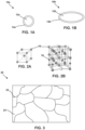
- FIG. 1A is a conceptual and schematic diagram illustrating an example core-shell nanoparticle.
- Example nanoparticle 10a includes an iron-based core 12a, and a shell 14a.
- iron-based core 12a may be ferromagnetic, and have a high saturation magnetization.
- Shell 14a may substantially coat or surround iron-based core 12a.
- Shell 14a may include a non-magnetic material, an anti-ferromagnetic material, or a ferromagnetic material. In other examples, shell 14a may include a ferromagnetic material.
- the difference between one or both of the magnetization and thermal expansion coefficient of iron-based core 12a and shell 14a, and the reduction in packing density of a composition include nanoparticle 10a because of the presence of shell 14a spacing iron-based core 12a from a neighboring core, may ultimately promote a relatively increased coercivity of materials including nanoparticle 10a, compared to materials including nanoparticles without shell 14a.
- iron-based core 12b is an ellipsoid with a ratio of a longitudinal diameter to a transverse diameter of at least about 2.
- the ratio of the longitudinal diameter to the transverse diameter may be at least about 3, or about 5, or about 10.
- the ratio of the longitudinal diameter to the transverse diameter may be about 2, or about 5.
- nanoparticle may exhibit a shape anisotropy, for example, as a result of the ellipsoidal shape.
- the shape anisotropy may contribute to increased magnetic anisotropy.
- shell 14a or 14b may include one or more of nonmagnetic materials, such as silica, aluminum oxide, silicon nitride, aluminum nitride, zinc oxide or anti-ferromagnetic materials, such as manganese nitride, or ferromagnetic materials, such as iron oxide, or ferromagnetic materials, such as Fe 4 N, and Fe 16 N 2 .
- shell 14a may have a thickness between about 1 nm and about 10 nm.
- shell 14a may have a thickness of about 1 nm, or about 5 nm, or about 10 nm.
- iron-based cores 12a or 12b include an ⁇ "-Fe 16 N 2 phase.
- the terms Fe 16 N 2 , ⁇ "-Fe 16 N 2 , ⁇ "-Fe 16 N 2 phase, and ⁇ "-Fe 16 N 2 phase domain may be used interchangeably to refer to a ⁇ "-Fe 16 N 2 phase domain within a material.
- the ⁇ "-Fe 16 N 2 phase may exhibit an intrinsic magnetocrystalline anisotropy, as discussed with reference to FIGS. 2A and 2B .
- FIG. 2A is a conceptual and schematic diagram illustrating a unit crystallographic cell of ⁇ -Fe.
- FIG. 2A shows a unit cell including iron atoms 16 in an isotropic arrangement.
- FIG. 2B is a conceptual and schematic diagram illustrating a unit crystallographic cell of ⁇ "-Fe 16 N 2 .
- FIG. 2B shows eight (8) iron unit cells in a strained state with nitrogen atoms 18 in interstitial spaces between iron atoms 16 to form the Fe 16 N 2 iron nitride unit cell. As shown in FIG. 2B , in the ⁇ "-Fe 16 N 2 phase, nitrogen atoms 18 are aligned along the (002) (iron) crystal planes.
- the iron nitride unit cell is distorted such that the length of the unit cell along the ⁇ 001> axis is approximately 6.28 angstroms ( ⁇ ) while the length of the unit cell along the ⁇ 010> and ⁇ 100> axes is approximately 5.72 ⁇ .
- the ⁇ "-Fe 16 N 2 unit cell may be referred to as a body-centered tetragonal unit cell when in the strained state.
- the ⁇ 001> axis may be referred to as the c-axis of the unit cell.
- the c-axis may be the magnetic easy axis of the ⁇ "-Fe 16 N 2 unit cell.
- core-shell nanoparticles 10a or 10b may have at least one Fe 16 N 2 iron nitride crystal.
- such an anisotropic particle may include a plurality of iron nitride crystals, at least some (or all) of which are Fe 16 N 2 crystals.
- the ⁇ "-Fe 16 N 2 phase has high saturation magnetization and magnetic anisotropy constant.
- the high saturation magnetization and magnetic anisotropy constants result in a magnetic energy product that may be higher than rare earth magnets.
- experimental evidence gathered from thin film ⁇ "-Fe 16 N 2 permanent magnets suggests that bulk Fe 16 N 2 permanent magnets may have desirable magnetic properties, including an energy product of as high as about 130 MegaGauss * Oerstads (MGOe), which is about two times the energy product of NdFeB (which has an energy product of about 60 MGOe).
- MGOe MegaGauss * Oerstads
- NdFeB which has an energy product of about 60 MGOe.
- iron and nitrogen are abundant elements, and thus are relatively inexpensive and easy to procure.
- nanoparticles 10a or 10b may have a relatively high coercivity.
- nanoparticles 10a or 10b may have a coercivity of at least about 600 Oe.
- nanoparticles 10a or 10b may have a coercivity of at least about 1000 Oe.
- nanoparticles 10a or 10b may have a coercivity of about 1000 Oe.
- nanoparticles 10a or 10b may include at least one of FeN, Fe 2 N (e.g., ⁇ -Fe 2 N), Fe 3 N (e.g., ⁇ -Fe 3 N), Fe 4 N (e.g., ⁇ '-Fe 4 N), Fe 2 N 6 , Fe 8 N, Fe 16 N 2 (e.g., ⁇ "-Fe 16 N 2 ), or FeN x (where x is between about 0.05 and about 0.5) .
- the nanoparticles 10a or 10b include elemental iron and may include cobalt, nickel, dopants, or the like.
- the cobalt, nickel, dopants, or the like may be at least partially removed after the milling process using one or more suitable techniques.
- Dopants within the nanoparticles may include, for example, at least one of aluminum (Al), manganese (Mn), lanthanum (La), chromium (Cr), cobalt (Co), titanium (Ti), nickel (Ni), zinc (Zn), a rare earth metal, boron (B), carbon (C), phosphorous (P), silicon (Si), or oxygen (O).
- Compositions for example, mixtures, including example nanoparticles 10a or 10b may be compacted and shaped or otherwise further processed to form bulk magnetic materials, such as permanent magnets.
- example alloy compositions may include nanoparticles 10a or 10b.
- FIG. 3 is a conceptual and schematic diagram illustrating a microstructure of an example alloy composition 20 including grain boundaries 22 between iron-based grains 24.
- iron-based grains 24 include material substantially similar to that of iron-based cores 12a or 12b described with reference to FIGS. 1A and 1B .
- grain boundaries 22 include material substantially similar to that of shells 14a and 14B described with reference to FIGS. 1A and 1B .
- example alloy composition 20 may be prepared by compacting one or both of nanoparticles 10a or 10b.
- alloy composition 20 may be prepared by any suitable techniques for engineering the compositions or phase constitutions of grains and grain boundaries, or the microstructure of alloy composition 20, including for example, casting, annealing, and nitriding.
- alloy composition 20 may be further processed, for example, by one or more of molding, compacting, pressurizing, or annealing, to prepare bulk magnetic materials, such as permanent magnets.
- example core-shell nanoparticles and example alloy compositions according to the disclosure may be used to prepare bulk magnetic materials, such as permanent magnets.
- FIG. 4 is a conceptual and schematic diagram illustrating an example system 30 for forming a core-shell nanoparticle by treatment of a core nanoparticle with a salt composition 34.
- System 30 may include a container 31.
- Container 31 can be any suitable rigid, semi-rigid, or flexible container dimensioned to contain a sample holder 32 and salt composition 34.
- Sample holder 32 holds a composition including iron-based core 12a or 12b.
- iron-based core 12a or 12b includes one or more of iron, iron nitride, ⁇ "-Fe 16 N 2 , or ⁇ '-Fe(Co)(N).
- salt composition 34 includes one or more precursors of at least one of silica, aluminum oxide, silicon nitride, aluminum nitride, manganese nitride, zinc oxide, iron oxide, ferromanganese, Fe 4 N, or Fe 16 N 2 .
- salt composition 34 may include one or more of a liquid, a solution, a polymer, or a gel.
- the salt composition 34 deposits shell 14a or 14b on core 12a or 12b, when core 12a or 12b is immersed in salt composition 34 for a predetermined amount of time.
- system 30 may spray, coat, or otherwise immerse sample holder 32 in a static batch or a moving flow of salt composition 34.
- FIG. 5 is a flow diagram illustrating an example technique for forming a core-shell nanoparticle by treating iron-based core 12a or 12b with salt composition 34.
- the example technique of FIG. 5 is described with reference to system 30 of FIG. 4 .
- the example technique of FIG. 5 may be implemented using any suitable system.
- the example technique of FIG. 5 may optionally include reducing an iron precursor to form iron-based cores 12a or 12b (40).
- the iron precursor may include, for example, at least one of iron (Fe), FeCl 3 , Fe 2 O 3 , or Fe 3 O 4 .
- the iron precursor may include a bulk or powder sample including Fe, FeCl 3 , or iron (e.g., Fe 2 O 3 or Fe 3 O 4 ), or combinations thereof.
- the precursor may include a powder including particles.
- Reducing the precursor may include reducing or removing oxygen content in the precursor.
- an oxygen reduction process can be carried out by exposing the precursor to hydrogen gas.
- the hydrogen may react with any oxygen present in the precursor, removing oxygen.
- such a reduction step may form substantially pure iron within the precursor including iron (e.g., iron with less than about 10 at. % dopants).
- reducing the precursor may include using an acid cleaning technique. For example, diluted hydrochloric acid, with a concentration between about 5% by volume and about 50% by volume can be used to wash oxygen from the precursor to form iron-based core 12a or 12b.
- the example technique of FIG. 5 may optionally include nitriding iron-based core 12a or 12b (42).
- Nitriding iron-based core 12a or 12b (42) may form an iron nitride phase in iron-based core 12a or 12b, and may proceed in any one of a number of manners.
- nitrogen from a nitrogen source is combined with iron to form iron nitride.
- Such a nitrogen source may be the same as or similar to nitrogen sources described in elsewhere in this disclosure, such as at least one of ammonia, ammonium nitrate, an amide-containing material, or a hydrazine-containing material.
- nitriding iron-based core 12a or 12b 42 may include heating iron-based core 12a or 12b to a selected temperature for a time sufficient to allow diffusion of nitrogen to a predetermined concentration substantially throughout a volume including iron.
- the heating time and temperature are related, and may also be affected by the composition and/or geometry of the volume including iron.
- the heating may include heating to a temperature between about 125 °C and about 600 °C for between about 2 hours and about 9 hours.
- nitriding the anisotropic particle including iron may include exposing to an atomic nitrogen substance, which diffuses into the volume including iron.
- the atomic nitrogen substance may be supplied as diatomic nitrogen (N 2 ), which is then separated (cracked) into individual nitrogen atoms.
- the atomic nitrogen may be provided from another atomic nitrogen precursor, such as ammonia (NH 3 ).
- the atomic nitrogen may be provided from urea (CO(NH 2 ) 2 ).
- the nitrogen may be supplied in a gas phase alone (e.g., substantially pure ammonia or diatomic nitrogen gas) or as a mixture with a carrier gas.
- the carrier gas is argon (Ar).
- nitriding the anisotropic particle including iron may include a urea diffusion process, in which urea is utilized as a nitrogen source (e.g., rather than diatomic nitrogen or ammonia).
- Urea also referred to as carbamide
- Urea is an organic compound with the chemical formula CO(NH 2 ) 2 .
- Urea may be heated, e.g., within a furnace enclosing the anisotropic particle including iron, to generate decomposed nitrogen atoms which may diffuse into the volume including iron.
- the constitution of the resulting nitrided iron material may controlled to some extent by the temperature of the diffusion process as well as the ratio (e.g., the weight ratio) of the iron-containing workpiece to urea used for the process. Further details regarding these nitriding processes (including urea diffusion) may be found in International Patent Application No. PCT/US12/51382, filed August 17, 2012 .
- nitriding iron-based core 12a or 12b (42) includes autoclaving iron-based cores 12a or 12b at a predetermined pressure, at a predetermined temperature, for a predetermined period of time, in a nitrogen-rich environment, for example, using example autoclave nitriding techniques described elsewhere in the disclosure.
- the predetermined pressure may be greater than about 100 atmospheres, or at least about 100atmospheres.
- diffusion of nitrogen species increases with pressure. Increasing the pressure, increases nitrogen diffusion. Using a pressure of at least about 100 atmospheres may increase the diffusion rate by at least about 10 times. Increasing the diffusion rate may promote the nitriding result, for example, for increasing the rate of iron nitride formation.
- the example technique of FIG. 5 also includes depositing shell 14a or 14b on iron-based core 12a or 12b to form core-shell nanoparticle 10a or 10b (44).
- Depositing shell 14a or 14b on iron-based core 12a or 12b (44) may include immersing sample holder 32 including iron-based core 12a or 12b in salt composition 34 for a predetermined period of time.
- the technique of FIG. 5 may additionally include, after depositing shell 14a or 14b on iron-based core 12a or 12b (44), separating nanoparticle 10a or 10b from salt composition 34 (48).
- the separating may include screening or filtering, for example, through a screen or a mesh.
- Nanoparticles 10a or 10b may be washed after the separating to remove any adhering or otherwise residual salt composition 34 on nanoparticles 10a or 10b.
- the example technique of FIG. 5 may optionally include, after depositing shell 14a or 14b on iron-based core 12a or 12b (44), drying the core-shell nanoparticles 10a or 10b (50).
- the drying may include oven drying, convection drying, or fluidized drying.
- the example technique of FIG. 5 also may optionally include, after depositing shell 14a or 14b on iron-based core 12a or 12b (44), nitriding the core-shell nanoparticles 10a or 10b (52).
- the nitriding (52) may be performed similar to or substantially the same as nitriding iron-based core 12a or 12b (42).
- the nitriding may help introduce an iron nitride phase within nanoparticle 10a or 10b, for example, within one or both of core 12a or 12b, or shell 14a or 14b.
- the technique of FIG. 5 includes only one of steps (42) and (52).
- the technique of FIG. 5 includes both of steps (42) and (52).
- the technique of FIG. 5 may omit both of steps (42) and (52).
- the example technique of FIG. 5 may further optionally include, after depositing shell 14a or 14b on iron-based core 12a or 12b (44), annealing nanoparticles 10a or 10b (54).
- the annealing may include exposing nanoparticles 10a or 10b to a magnetic field having a predetermined strength at a predetermined temperature for a predetermined period of time.
- the annealing may include heating the particles to a temperature between about 100 °C and about 250 °C, such as between about 120 °C and about 220 °C, for example, between about 180 °C and 220 °C.
- the annealing process may continue for a predetermined time that is sufficient to allow diffusion of the nitrogen atoms to the appropriate interstitial spaces in the iron crystal lattice. Such diffusion may promote the formation of iron nitride phases, and may promote the conversion of disordered iron nitride phases, for example, Fe 8 N, into ordered iron nitride phases, for example, Fe 16 N 2 . However, heating at temperatures greater than about 250 °C may reduce the formation of ordered iron nitride phases, or may degrade previously-formed ordered iron nitride phases such as Fe 16 N 2 . In some examples, the annealing process continues for between about 20 hours and about 200 hours, such as between about 40 hours and about 60 hours.
- the annealing process may occur under an inert atmosphere, such as Ar, to reduce or substantially prevent oxidation of the iron. Further, in some implementations, the temperature is held substantially constant. The annealing may result in magnetic material including at least one ⁇ "-Fe 16 N 2 phase domain.
- the annealing may include exposing nanoparticles 10a or 10b to an external magnetic field during the annealing process.
- Annealing iron nitride materials in the presence of an applied magnetic field may enhance the Fe 16 N 2 phase domain formation in iron nitride materials.
- Increased volume fractions of ⁇ "-Fe 16 N 2 phase domains may improve the magnetic properties of core-shell nanoparticles including iron nitride.
- Improved magnetic properties may include, for example, coercivity, magnetization, and magnetic orientation.
- an applied magnetic field during annealing may be at least 0.2 Tesla (T).
- the temperature at which the magnetic field annealing is performed may at least partially depend upon further elemental additions to the iron nitride base composition and the approach used to initially synthesize the iron nitride base composition.
- the magnetic field may be at least about 0.2T, at least about 2 T, at least about 2.5 T, at least about 6 T, at least about 7 T, at least about 8 T, at least about 9 T, at least about 10 T, or higher.
- the magnetic field is between about 5 T and about 10 T. In other examples, the magnetic field is between about 8 T and about 10 T. Further details regarding annealing the materials including iron and nitrogen may be found in U.S. Provisional Application No. 62/019,046, filed June 30, 2014 .
- the example system of FIG. 4 and the example technique of FIG. 5 may be used to form core-shell nanoparticles according to the disclosure.
- Other example systems and techniques for forming core-shell nanoparticles are described with reference to FIGS. 6-9 .
- FIG. 6 is a conceptual and schematic diagram illustrating an example milling system 60 for forming example core-shell nanoparticles by milling.
- Milling system 10 may be operated in a rolling mode, in which a bin 62 of milling system 60 rotates about a horizontal axis of bin 62, as indicated by arrow 69.
- milling media 65 such as milling spheres, milling bars, or the like
- iron-containing material 64 may include iron-based cores 12a or 12b.
- bin 12 includes a salt composition 66.
- salt composition 66 may include one or more precursors of at least one of silica, aluminum oxide, silicon nitride, aluminum nitride, manganese nitride, zinc oxide, iron oxide, ferromanganese, Fe 4 N, Fe 8 N, or Fe 16 N 2 .
- Salt composition 66 deposits respective shells 14a or 14b on iron-based cores 12a or 12b.
- salt composition 66 may include one or more of a solid, a slurry, a paste, a suspension, a liquid, a solution, a polymer, or a gel.
- milling media 65 may exert pressure on iron-containing material 64 and salt composition 66, which may result in cold welding of material from salt composition 66 onto iron-containing material 64.
- the milling may result in cold welding of material from salt composition 66 onto iron-based core 12a or 12b, to form a cold welded shell 14a or 14b.
- the cold welding may thus allow shell 14a or 14b to be deposited on core 12a or 12b, without heating, or without requiring a molten phase of shell material.
- milling system 60 may include additional components.
- milling system 60 may include a nitrogen source, for nitriding iron-containing material 64 before, during, or after, depositing shell 14a or 14b on iron-based cores 12a or 12b.
- the nitrogen source may include at least one of ammonia, ammonium nitrate, an amide-containing material, or a hydrazine-containing material.
- the amide-containing material may include at least one of a liquid amide, a solution containing an amide, carbamide, methanamide, benzamide, or acetamide.
- the hydrazine-containing material may include at least one of a hydrazine or a solution containing the hydrazine.
- salt composition 66 may include the nitrogen source.
- a nitriding composition may include a nitrogen source.
- the nitrogen source may be contained in a dispenser in milling system 60.
- iron-containing material 64 may include an iron precursor instead of iron-based cores 12a or 12b.
- the iron precursor may include at least one of iron (Fe), FeCl 3 , Fe 2 O 3 , or Fe 3 O 4 .
- Bin 62 may contain a reducing environment, as described elsewhere in the disclosure, and may mill the iron precursor in the reducing environment to form iron-based cores 12a or 12b.
- milling system 60 may mill the iron precursor with the nitrogen source to nitride the iron precursor as iron-based cores 12a or 12b are formed.
- milling media 65 may include a sufficiently hard material that, when contacting iron-containing material 64 with sufficient force, will wear iron-containing raw material 64 and cause particles of iron-containing material 64 to, on average, have a smaller size, for example, smaller particles 68.
- milling media 65 may be formed of steel, stainless steel, or the like.
- the material from which milling media 65 are formed may not chemically react with iron-containing material 64 and/or the nitrogen source.
- milling media 65 such as milling spheres, may have an average diameter between about 5 millimeters (mm) and about 20 mm.
- the mass ratio of the total mass of milling media 65 to the total mass of iron-containing material 64 may be between about 1:1 to about 50:1, for example, about 20:1.
- milling system 60 may be used to perform the example technique of FIG. 7 . While the example technique of FIG. 7 is described with reference to components of milling system 60, the example technique of FIG. 7 may be performed with other milling systems.
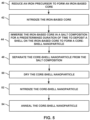
- FIG. 7 is a flow diagram illustrating an example technique for forming core-shell nanoparticle 10a or 10b by milling.
- the technique of FIG. 7 may optionally include reducing an iron precursor to form iron-based cores 12a or 12b (70).
- the reducing 70 may be performed similarly to the reducing 40 described with reference to the example technique of FIG. 5 .
- the reducing may be performed by milling system 60.
- bin 62 may mill iron precursor in a reducing environment, as described elsewhere in the disclosure.
- the example technique of FIG. 7 may optionally include nitriding iron-based core 12a or 12b (72).
- the nitriding 72 may be performed similarly to the nitriding 42 described with reference to the example technique of FIG. 5 .
- the nitriding 72 may be performed using milling system 60.
- the nitriding (72) may include milling iron-based core 12a or 12b with a nitrogen source for a predetermined period of time.
- salt composition 66 may include the nitrogen source.
- a nitriding composition in bin 62 may include the nitrogen source.
- the nitrogen source may be similar to nitrogen sources described elsewhere in the disclosure.
- the technique of FIG. 7 includes depositing shell 14a or 14b on iron-based core 12a or 12b, by milling iron-based core 12a or 12b with salt composition 66 for a predetermined period of time (74).
- bin 62 of milling system 60 may be rotated at a rate sufficient to cause mixing of the components in bin 62 (e.g., milling media 65, iron-containing material 64, the and salt composition 66) and cause milling media 65 to mill iron-containing material 64 and salt composition 66 so as to cause a shell to be deposited from salt composition 66 onto iron-based cores 12a or 12b in iron-containing material 64.
- bin 62 may be rotated at a rotational speed of between about 500 revolutions per minute (rpm) to about 2000 rpm, such as between about 600 rpm and about 650 rpm, about 600 rpm, or about 650 rpm.
- the depositing 74 may initially include milling iron-based material 64 with one of salt composition 66 or the nitriding composition, and may subsequently include milling iron-based material 64 with the other of salt composition 66 or the nitriding composition.
- the nitriding composition may be introduced into salt composition 66, or bin 62 may be progressively exposed to the nitrogen source, as the depositing 74 progresses.
- nanoparticle 10a or 10b may be formed by respectively depositing shell 14a or 14b on core 12a or 12b.
- the example technique of FIG. 7 may include, after the depositing 74, separating nanoparticle 10a or 10b from salt composition 66 (78).
- the separating 78 may be performed similarly to separating 48 described with reference to the example technique of FIG. 5 .
- the example technique of FIG. 7 may include, after the depositing 74, drying the core-shell nanoparticles 10a or 10b (80).
- the drying 80 may be performed similarly to the drying 50 described with reference to the example technique of FIG. 5 .
- the example technique of FIG. 7 may include, after the depositing 74, nitriding the core-shell nanoparticles 10a or 10b (82).
- the nitriding 82 may be performed similarly to the nitriding 52 described with reference to the example technique of FIG. 5 .
- the example technique of FIG. 7 may include, after the depositing 74, annealing nanoparticles 10a or 10b (84).
- the annealing 84 may be performed similarly to the annealing 54 described with reference to the example technique of FIG. 5 .
- the example system of FIG. 6 or the example technique of FIG. 7 may be used to form core-shell nanoparticles according to the disclosure.
- Other example systems and techniques for forming core-shell nanoparticles are described with reference to FIGS. 8 and 9 .
- FIG. 8 is a flow diagram illustrating an example technique for treating a composition including an iron-based material.
- the example technique of FIG. 8 includes treating a composition including core-shell nanoparticle 10a or 10b.
- the composition may include any iron-based material, for example, elemental iron, iron nitride, ⁇ "-Fe 16 N 2 , or ⁇ '-Fe(Co)(N).
- the iron-based material may include iron-based workpieces.
- workpieces may include grains or powders, such as spheres, cylinders, flecks, flakes, regular polyhedra, irregular polyhedra, and any combination thereof.
- workpieces may include a dimension that is longer, e.g., much longer, than other dimensions of the workpiece.
- Example workpieces with a dimension longer than other dimensions include fibers, wires, filaments, cables, films, thick films, foils, ribbons, sheets, or the like.
- workpieces may not have a dimension that is longer than other dimensions of the workpiece.
- workpieces may include nanoparticles, for example, core-shell nanoparticles.
- the workpieces may be further processed to form bulk magnets.
- the workpieces may be sintered, bonded, or both sintered and bonded together directly to form a bulk magnet.
- the example technique of FIG. 8 includes autoclaving the composition at a predetermined pressure, at a predetermined temperature, for a predetermined period of time, in an environment including a nitrogen source (90).
- the example technique of FIG. 8 may include any suitable high-pressure nitriding step.
- the autoclaving 90 includes heating the composition to a temperature greater than about 200 °F.
- the autoclaving 90 includes, simultaneously with the heating, pressurizing the composition to a pressure between about 1 atmospheres and about 100 atmospheres, or greater than 100 atmospheres.
- the autoclaving 90 nitrides the composition, for example, by introducing an iron nitride phase in one or both of core 12a or 12b and shell 14a or 14b of nanoparticle 10a or 10b.
- diffusion of nitrogen species increases with pressure.
- Increasing the pressure for example, by autoclaving, increases nitrogen diffusion.
- Using a pressure of at least about 100 atmospheres may increase the diffusion rate by at least about 10 times.
- Increasing the diffusion rate may promote the nitriding result, for example, for increasing the rate of iron nitride formation.
- the example technique of FIG. 8 may include milling the composition with the nitrogen source for a predetermined period of time. The milling may be performed similar to the milling 74 described with reference to FIG. 7 .
- the nitrogen source used in the autoclaving (90) or the milling includes at least one of ammonia, ammonium nitrate, an amide-containing material, or a hydrazine-containing material.
- the amide-containing material includes at least one of a liquid amide, a solution containing an amide, carbamide, methanamide, benzamide, or acetamide.
- the hydrazine-containing material includes at least one of a hydrazine or a solution containing the hydrazine.
- the example technique of FIG. 8 may optionally include, after the autoclaving (90) or the milling, annealing the deposited iron-based core (92).
- the annealing 92 may be performed similarly to the annealing 54 described with reference to the example technique of FIG. 5 .
- the example technique of FIG. 8 may be used to treat a composition comprising iron-based materials, for example, iron-based workpieces including core-shell nanoparticles, for example, to nitride iron-based materials to introduce an iron nitride phase.
- iron-based materials for example, iron-based workpieces including core-shell nanoparticles, for example, to nitride iron-based materials to introduce an iron nitride phase.
- the shape anisotropy H S 4 ⁇ . ⁇ N.Ms, where M S is the saturation magnetization (200 emu/g for Fe 16 N 2 ).
- the packing factor P 0.52 for close simple cubic packed ellipsoids.
- the coercivity depended on the ratio of the length of the particles (c) to the diameter of the particles (a), as set forth in TABLE 1. Table 1 c/a ⁇ N H S (Oe) Hc(Oe) 2 0.24 4524 2171 3 0.34 6409 3076 7 0.45 8482 4072
- the coercivity H C of ellipsoidal particles of Fe 16 N 2 including a non-magnetic shell of thickness h was calculated for varying particle dimensions, where a, b, and c are the three ellipsoidal diameters, using the.
- Example core-shell nanoparticles were prepared by sputtering an anti-ferromagnetic MnN shell on ellipsoidal Fe 16 N 2 cores.
- the magnetization behavior of the example core-shell nanoparticles was studied.
- FIG. 9 is a diagram illustrating a hysteresis loop of magnetization versus applied magnetic field at room temperature for example nanoparticles including Fe 16 N 2 cores and MnN shells. A relatively high coercivity of about 1605 Oe was achieved.
- Example core-shell nanoparticles were prepared by ammonia nitriding ellipsoidal Fe particles. Fe 16 N 2 initially formed as a thin shell at the surfaces of reduced Fe particles, and the thickness of the Fe 16 N 2 increased as a function of nitriding time, to eventually form Fe/ Fe 16 N 2 core-shell nanoparticles.
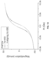
- FIG. 11 is a diagram illustrating a hysteresis loop of magnetization versus applied magnetic field at room temperature for the example nanoparticles of FIG. 10 .
- a coercivity of about 1010 Oe and a magnetization saturation of about 150 emu/g were observed.
- FIG. 12 is a diagram illustrating the x-ray diffraction data for the example nanoparticles including Fe cores and Fe 16 N 2 shells, for sample FNP224, after nitriding for 50 hours using ammonia.
- FIG. 13 is a diagram illustrating a hysteresis loop of magnetization versus applied magnetic field at room temperature for the example nanoparticles of FIG. 12 .
- a coercivity of about 650 Oe and a magnetization saturation of about 50 emu/g were observed. As shown in FIGS. 10 and 12 , the saturation magnetization decreased to about 50 emu/g from about 150 emu/g as the shell was developed into the core.
- FIG. 15 is a diagram illustrating a hysteresis loop of magnetization versus applied magnetic field at room temperature (300K) and low temperature (10K) for the example Fe nanoparticles.
- FIG. 16 is a diagram illustrating a hysteresis loop of magnetization versus applied magnetic field at room temperature (300K) and low temperature (10K) for the example core-shell nanoparticles having Fe cores and MnN shells. As shown in FIGS. 15 and 16 , the coercivity increased on using MnN shells.
Landscapes
- Chemical & Material Sciences (AREA)
- Engineering & Computer Science (AREA)
- Inorganic Chemistry (AREA)
- Nanotechnology (AREA)
- Organic Chemistry (AREA)
- Metallurgy (AREA)
- Mechanical Engineering (AREA)
- Materials Engineering (AREA)
- Power Engineering (AREA)
- Chemical Kinetics & Catalysis (AREA)
- Crystallography & Structural Chemistry (AREA)
- Biomedical Technology (AREA)
- Life Sciences & Earth Sciences (AREA)
- Health & Medical Sciences (AREA)
- General Health & Medical Sciences (AREA)
- Molecular Biology (AREA)
- General Chemical & Material Sciences (AREA)
- Powder Metallurgy (AREA)
- Soft Magnetic Materials (AREA)
- Hard Magnetic Materials (AREA)
- Manufacture Of Metal Powder And Suspensions Thereof (AREA)
Claims (12)
- Une nanoparticule (10a, 10b) comprenant :un cœur (12a, 12b) à base de fer, le cœur (12a, 12b) à base de fer comprenant du fer élémentaire et α"-Fe16N2
etune enveloppe (14a, 14b) antiferromagnétique,caractérisée en ce que le cœur (12a, 12b) est un ellipsoïde avec un rapport d'un diamètre maximal à un diamètre minimal d'au moins environ 2. - La nanoparticule (10a, 10b) de la revendication 1, dans laquelle l'enveloppe (14a, 14b) comprend au moins un élément parmi le nitrure de manganèse ou le ferromanganèse.
- La nanoparticule (10a, 10b) de la revendication 1, dans laquelle le cœur (12a, 12b) a une dimension principale comprise entre environ 20 nm et environ 100 nm.
- La nanoparticule (10a, 10b) de la revendication 1, dans laquelle l'enveloppe (14a, 14b) a une épaisseur comprise entre environ 1 nm et environ 10 nm.
- Un matériau magnétique massif comprenant une pluralité des nanoparticules (10a, 10b) de la revendication 1.
- Un procédé de formation de la nanoparticule (10a, 10b) de la revendication 1, par dépôt (44) d'une enveloppe (14a, 14b) sur un cœur (12a, 12b) à base de fer afin de former une nanoparticule (10a, 10b) à cœur-enveloppe par au moins un concassage du cœur (12a, 12b) à base de fer avec une composition saline (34, 66) pendant un laps de temps prédéterminé ; la composition saline (34, 66) comprenant au moins un élément parmi des précurseurs de silice, l'oxyde d'aluminium, le nitrure de silicium, le nitrure d'aluminium, le nitrure de manganèse, l'oxyde de zinc, l'oxyde de fer, le ferromanganèse, Fe4N, et Fe16N2.
- Le procédé de la revendication 6, dans lequel la composition saline (34, 66) comprend au moins un élément parmi un solide, une boue, une pâte, une suspension, un liquide, une solution, un polymère, ou un gel.
- Le procédé de la revendication 6, comprenant en outre, après le dépôt de l'enveloppe (14a, 14b) :la filtration (48) de la nanoparticule (10a, 10b) à cœur-enveloppe de la solution saline (34, 66), etle séchage (50) de la nanoparticule (10a, 10b) à cœur-enveloppe.
- Le procédé de la revendication 6, comprenant en outre, après le dépôt de l'enveloppe (14a, 14b), la nitruration (52) de la nanoparticule (10a, 10b) à cœur-enveloppe.
- Le procédé de la revendication 9, dans lequel la nitruration de la nanoparticule (10a, 10b) à cœur-enveloppe comprend l'autoclavage de la nanoparticule (10a, 10b) à cœur-enveloppe à une pression prédéterminée, à une température prédéterminée, pendant un laps de temps prédéterminé, dans un environnement riche en azote, la pression prédéterminée étant supérieure à 100 atmosphères.
- Le procédé de la revendication 10, dans lequel l'environnement riche en azote est généré par une source d'azote comprenant au moins un élément parmi l'ammoniac, le nitrate d'ammonium, un matériau contenant un amide, ou un matériau contenant de l'hydrazine.
- Le procédé de la revendication 6, comprenant en outre, après le dépôt de l'enveloppe (14a, 14b), le recuit (54) de la nanoparticule (10a, 10b) à cœur-enveloppe en présence d'un champ magnétique appliqué, le recuit (54) de la nanoparticule (10a, 10b) à cœur-enveloppe en présence d'un champ magnétique appliqué comprenant l'exposition de la nanoparticule (10a, 10b) à cœur-enveloppe à un champ magnétique ayant une intensité prédéterminée à une température prédéterminée pendant un laps de temps prédéterminé.
Applications Claiming Priority (3)
| Application Number | Priority Date | Filing Date | Title |
|---|---|---|---|
| US201662405661P | 2016-10-07 | 2016-10-07 | |
| EP17859257.2A EP3523813B1 (fr) | 2016-10-07 | 2017-10-06 | Nanoparticules à base de fer et grains |
| PCT/US2017/055531 WO2018067926A1 (fr) | 2016-10-07 | 2017-10-06 | Nanoparticules et grains à base de fer |
Related Parent Applications (2)
| Application Number | Title | Priority Date | Filing Date |
|---|---|---|---|
| EP17859257.2A Division-Into EP3523813B1 (fr) | 2016-10-07 | 2017-10-06 | Nanoparticules à base de fer et grains |
| EP17859257.2A Division EP3523813B1 (fr) | 2016-10-07 | 2017-10-06 | Nanoparticules à base de fer et grains |
Publications (2)
| Publication Number | Publication Date |
|---|---|
| EP4216238A1 EP4216238A1 (fr) | 2023-07-26 |
| EP4216238B1 true EP4216238B1 (fr) | 2025-05-21 |
Family
ID=61831942
Family Applications (2)
| Application Number | Title | Priority Date | Filing Date |
|---|---|---|---|
| EP23162454.5A Active EP4216238B1 (fr) | 2016-10-07 | 2017-10-06 | Nanoparticules et grains à base de fer |
| EP17859257.2A Active EP3523813B1 (fr) | 2016-10-07 | 2017-10-06 | Nanoparticules à base de fer et grains |
Family Applications After (1)
| Application Number | Title | Priority Date | Filing Date |
|---|---|---|---|
| EP17859257.2A Active EP3523813B1 (fr) | 2016-10-07 | 2017-10-06 | Nanoparticules à base de fer et grains |
Country Status (5)
| Country | Link |
|---|---|
| US (3) | US11161175B2 (fr) |
| EP (2) | EP4216238B1 (fr) |
| CN (1) | CN110073448B (fr) |
| AR (1) | AR109900A1 (fr) |
| WO (1) | WO2018067926A1 (fr) |
Families Citing this family (7)
| Publication number | Priority date | Publication date | Assignee | Title |
|---|---|---|---|---|
| US11875934B2 (en) * | 2018-05-28 | 2024-01-16 | Regents Of The University Of Minnesota | Iron-rich permanent magnet |
| CN111145986A (zh) * | 2018-11-01 | 2020-05-12 | 松下电器产业株式会社 | 压粉磁芯及其制造方法 |
| CN114222826A (zh) * | 2019-05-22 | 2022-03-22 | 尼龙磁学公司 | 具有高饱和磁化的矫顽力增强氮化铁纳米颗粒 |
| JP7764387B2 (ja) * | 2020-02-21 | 2025-11-05 | ニロン マグネティクス,インコーポレイティド | 異方性窒化鉄永久磁石 |
| JP7629764B2 (ja) * | 2021-03-15 | 2025-02-14 | 株式会社日立製作所 | 軟磁性鉄合金板およびその製造方法 |
| CN113363068B (zh) * | 2021-06-02 | 2022-09-20 | 安徽智磁新材料科技有限公司 | 一种铁钴基壳核软磁合金磁芯粉的制备方法 |
| CN117862495B (zh) * | 2024-03-11 | 2024-06-07 | 中国空气动力研究与发展中心低速空气动力研究所 | 一种FeCo纳米链金属粉末、FeCo@SiO2微波吸收材料及其制备方法 |
Family Cites Families (20)
| Publication number | Priority date | Publication date | Assignee | Title |
|---|---|---|---|---|
| JPH04242901A (ja) * | 1991-01-07 | 1992-08-31 | Sumitomo Metal Ind Ltd | 磁気冷凍用磁性体材料 |
| EP1662256A1 (fr) * | 2004-11-25 | 2006-05-31 | Spinomix S.A. | Particules magnétiques adaptées et procédé de fabrication correspondant |
| US20100054981A1 (en) * | 2007-12-21 | 2010-03-04 | Board Of Regents, The University Of Texas System | Magnetic nanoparticles, bulk nanocomposite magnets, and production thereof |
| US8455117B2 (en) * | 2009-03-04 | 2013-06-04 | Seagate Technology Llc | Bit-patterned stack with antiferromagnetic shell |
| US7964013B2 (en) * | 2009-06-18 | 2011-06-21 | University Of Louisiana At Lafayette | FeRh-FePt core shell nanostructure for ultra-high density storage media |
| JP5637362B2 (ja) | 2009-07-30 | 2014-12-10 | 富士フイルム株式会社 | 磁性粉末の製造方法 |
| JP5247754B2 (ja) * | 2010-03-30 | 2013-07-24 | 株式会社日立製作所 | 磁性材料及びその磁性材料を用いたモータ |
| JP2013254756A (ja) * | 2010-08-30 | 2013-12-19 | Hitachi Ltd | 焼結磁石 |
| JP5831866B2 (ja) | 2011-01-21 | 2015-12-09 | 戸田工業株式会社 | 強磁性粒子粉末及びその製造方法、並びに異方性磁石、ボンド磁石及び圧粉磁石 |
| US20120208026A1 (en) * | 2011-02-10 | 2012-08-16 | Xerox Corporation | Silica-Coated Magnetic Nanoparticles and Process for Making Same |
| JP6085301B2 (ja) | 2011-08-17 | 2017-02-22 | リージェンツ オブ ザ ユニバーシティ オブ ミネソタ | 窒化鉄永久磁石および窒化鉄永久磁石の形成技術 |
| WO2013042721A1 (fr) * | 2011-09-22 | 2013-03-28 | 戸田工業株式会社 | Procédé de fabrication d'une poudre ferromagnétique de nitrure de fer, aimant anisotrope, aimant aggloméré et aimant en poudre comprimée |
| KR101778164B1 (ko) * | 2012-02-03 | 2017-09-13 | 엘지전자 주식회사 | 코어-쉘 구조를 가지는 경-연자성 혼성 구조의 나노입자, 상기 나노입자를 이용하여 제조한 자석 및 이들의 제조방법 |
| CN102751063A (zh) * | 2012-07-20 | 2012-10-24 | 河北师范大学 | 一种具有零场冷却交换偏置效应的磁性带材及其制备方法 |
| US9604281B2 (en) * | 2013-03-13 | 2017-03-28 | Syracuse University | Method to control void formation in nanomaterials using core/alloy nanoparticles with stainless interfaces |
| CN106165027A (zh) | 2014-03-28 | 2016-11-23 | 明尼苏达大学董事会 | 包含涂覆的纳米颗粒的氮化铁磁性材料 |
| US9994949B2 (en) * | 2014-06-30 | 2018-06-12 | Regents Of The University Of Minnesota | Applied magnetic field synthesis and processing of iron nitride magnetic materials |
| JP6230513B2 (ja) * | 2014-09-19 | 2017-11-15 | 株式会社東芝 | 複合磁性材料の製造方法 |
| US20160379741A1 (en) * | 2015-06-26 | 2016-12-29 | Advanced Materials Corporation | Low-Cost Precursor for Synthesis of High Coercivity Fe-N Magnets |
| KR101639724B1 (ko) * | 2015-07-30 | 2016-07-15 | 한국생산기술연구원 | 촉매 또는 촉매 지지체용 복합입자 및 이의 제조방법 |
-
2017
- 2017-10-06 CN CN201780075593.XA patent/CN110073448B/zh active Active
- 2017-10-06 US US16/340,031 patent/US11161175B2/en active Active
- 2017-10-06 WO PCT/US2017/055531 patent/WO2018067926A1/fr not_active Ceased
- 2017-10-06 EP EP23162454.5A patent/EP4216238B1/fr active Active
- 2017-10-06 AR ARP170102805A patent/AR109900A1/es unknown
- 2017-10-06 EP EP17859257.2A patent/EP3523813B1/fr active Active
-
2021
- 2021-09-30 US US17/490,800 patent/US11837393B2/en active Active
-
2023
- 2023-10-26 US US18/494,838 patent/US12512238B2/en active Active
Also Published As
| Publication number | Publication date |
|---|---|
| US20200038951A1 (en) | 2020-02-06 |
| CN110073448B (zh) | 2021-10-15 |
| US12512238B2 (en) | 2025-12-30 |
| EP3523813A1 (fr) | 2019-08-14 |
| CN110073448A (zh) | 2019-07-30 |
| EP3523813B1 (fr) | 2023-05-31 |
| EP4216238A1 (fr) | 2023-07-26 |
| US11837393B2 (en) | 2023-12-05 |
| US20240055165A1 (en) | 2024-02-15 |
| US11161175B2 (en) | 2021-11-02 |
| EP3523813A4 (fr) | 2020-05-06 |
| US20220080500A1 (en) | 2022-03-17 |
| WO2018067926A1 (fr) | 2018-04-12 |
| AR109900A1 (es) | 2019-02-06 |
Similar Documents
| Publication | Publication Date | Title |
|---|---|---|
| US12512238B2 (en) | Iron-based nanoparticles and grains | |
| JP7385313B2 (ja) | 窒化鉄磁性材料の印加磁場合成及び処理 | |
| CN105849834A (zh) | 铁氮化物材料以及含铁氮化物材料的磁体 | |
| KR20170108082A (ko) | 이방성 형상의 질화철 분말 | |
| AU2016211830A1 (en) | Preservation of strain in iron nitride magnet | |
| US20240076764A1 (en) | Iron nitride compositions | |
| JP2013254756A (ja) | 焼結磁石 | |
| US11361887B2 (en) | Magnetic material comprising FeNi ordered alloy and manufacturing method for the same | |
| Wang et al. | Iron-based nanoparticles and grains |
Legal Events
| Date | Code | Title | Description |
|---|---|---|---|
| PUAI | Public reference made under article 153(3) epc to a published international application that has entered the european phase |
Free format text: ORIGINAL CODE: 0009012 |
|
| STAA | Information on the status of an ep patent application or granted ep patent |
Free format text: STATUS: THE APPLICATION HAS BEEN PUBLISHED |
|
| AC | Divisional application: reference to earlier application |
Ref document number: 3523813 Country of ref document: EP Kind code of ref document: P |
|
| AK | Designated contracting states |
Kind code of ref document: A1 Designated state(s): AL AT BE BG CH CY CZ DE DK EE ES FI FR GB GR HR HU IE IS IT LI LT LU LV MC MK MT NL NO PL PT RO RS SE SI SK SM TR |
|
| STAA | Information on the status of an ep patent application or granted ep patent |
Free format text: STATUS: REQUEST FOR EXAMINATION WAS MADE |
|
| 17P | Request for examination filed |
Effective date: 20231127 |
|
| RBV | Designated contracting states (corrected) |
Designated state(s): AL AT BE BG CH CY CZ DE DK EE ES FI FR GB GR HR HU IE IS IT LI LT LU LV MC MK MT NL NO PL PT RO RS SE SI SK SM TR |
|
| STAA | Information on the status of an ep patent application or granted ep patent |
Free format text: STATUS: EXAMINATION IS IN PROGRESS |
|
| 17Q | First examination report despatched |
Effective date: 20240910 |
|
| GRAP | Despatch of communication of intention to grant a patent |
Free format text: ORIGINAL CODE: EPIDOSNIGR1 |
|
| STAA | Information on the status of an ep patent application or granted ep patent |
Free format text: STATUS: GRANT OF PATENT IS INTENDED |
|
| RIC1 | Information provided on ipc code assigned before grant |
Ipc: B82Y 25/00 20110101ALN20241204BHEP Ipc: C22C 38/00 20060101ALI20241204BHEP Ipc: B22F 9/20 20060101ALI20241204BHEP Ipc: B22F 1/16 20220101ALI20241204BHEP Ipc: B22F 1/054 20220101ALI20241204BHEP Ipc: H01F 1/06 20060101ALI20241204BHEP Ipc: H01F 1/00 20060101AFI20241204BHEP |
|
| RIC1 | Information provided on ipc code assigned before grant |
Ipc: B82Y 25/00 20110101ALN20241209BHEP Ipc: C22C 38/00 20060101ALI20241209BHEP Ipc: B22F 9/20 20060101ALI20241209BHEP Ipc: B22F 1/16 20220101ALI20241209BHEP Ipc: B22F 1/054 20220101ALI20241209BHEP Ipc: H01F 1/06 20060101ALI20241209BHEP Ipc: H01F 1/00 20060101AFI20241209BHEP |
|
| INTG | Intention to grant announced |
Effective date: 20241219 |
|
| RAP3 | Party data changed (applicant data changed or rights of an application transferred) |
Owner name: REGENTS OF THE UNIVERSITY OF MINNESOTA |
|
| GRAS | Grant fee paid |
Free format text: ORIGINAL CODE: EPIDOSNIGR3 |
|
| GRAA | (expected) grant |
Free format text: ORIGINAL CODE: 0009210 |
|
| STAA | Information on the status of an ep patent application or granted ep patent |
Free format text: STATUS: THE PATENT HAS BEEN GRANTED |
|
| AC | Divisional application: reference to earlier application |
Ref document number: 3523813 Country of ref document: EP Kind code of ref document: P |
|
| AK | Designated contracting states |
Kind code of ref document: B1 Designated state(s): AL AT BE BG CH CY CZ DE DK EE ES FI FR GB GR HR HU IE IS IT LI LT LU LV MC MK MT NL NO PL PT RO RS SE SI SK SM TR |
|
| REG | Reference to a national code |
Ref country code: GB Ref legal event code: FG4D |
|
| REG | Reference to a national code |
Ref country code: CH Ref legal event code: EP |
|
| REG | Reference to a national code |
Ref country code: DE Ref legal event code: R096 Ref document number: 602017089638 Country of ref document: DE |
|
| REG | Reference to a national code |
Ref country code: IE Ref legal event code: FG4D |
|
| REG | Reference to a national code |
Ref country code: NL Ref legal event code: MP Effective date: 20250521 |
|
| PG25 | Lapsed in a contracting state [announced via postgrant information from national office to epo] |
Ref country code: FI Free format text: LAPSE BECAUSE OF FAILURE TO SUBMIT A TRANSLATION OF THE DESCRIPTION OR TO PAY THE FEE WITHIN THE PRESCRIBED TIME-LIMIT Effective date: 20250521 Ref country code: PT Free format text: LAPSE BECAUSE OF FAILURE TO SUBMIT A TRANSLATION OF THE DESCRIPTION OR TO PAY THE FEE WITHIN THE PRESCRIBED TIME-LIMIT Effective date: 20250922 Ref country code: ES Free format text: LAPSE BECAUSE OF FAILURE TO SUBMIT A TRANSLATION OF THE DESCRIPTION OR TO PAY THE FEE WITHIN THE PRESCRIBED TIME-LIMIT Effective date: 20250521 |
|
| REG | Reference to a national code |
Ref country code: LT Ref legal event code: MG9D |
|
| PG25 | Lapsed in a contracting state [announced via postgrant information from national office to epo] |
Ref country code: NO Free format text: LAPSE BECAUSE OF FAILURE TO SUBMIT A TRANSLATION OF THE DESCRIPTION OR TO PAY THE FEE WITHIN THE PRESCRIBED TIME-LIMIT Effective date: 20250821 Ref country code: GR Free format text: LAPSE BECAUSE OF FAILURE TO SUBMIT A TRANSLATION OF THE DESCRIPTION OR TO PAY THE FEE WITHIN THE PRESCRIBED TIME-LIMIT Effective date: 20250822 |
|
| PG25 | Lapsed in a contracting state [announced via postgrant information from national office to epo] |
Ref country code: PL Free format text: LAPSE BECAUSE OF FAILURE TO SUBMIT A TRANSLATION OF THE DESCRIPTION OR TO PAY THE FEE WITHIN THE PRESCRIBED TIME-LIMIT Effective date: 20250521 Ref country code: NL Free format text: LAPSE BECAUSE OF FAILURE TO SUBMIT A TRANSLATION OF THE DESCRIPTION OR TO PAY THE FEE WITHIN THE PRESCRIBED TIME-LIMIT Effective date: 20250521 |
|
| PG25 | Lapsed in a contracting state [announced via postgrant information from national office to epo] |
Ref country code: BG Free format text: LAPSE BECAUSE OF FAILURE TO SUBMIT A TRANSLATION OF THE DESCRIPTION OR TO PAY THE FEE WITHIN THE PRESCRIBED TIME-LIMIT Effective date: 20250521 |
|
| PG25 | Lapsed in a contracting state [announced via postgrant information from national office to epo] |
Ref country code: HR Free format text: LAPSE BECAUSE OF FAILURE TO SUBMIT A TRANSLATION OF THE DESCRIPTION OR TO PAY THE FEE WITHIN THE PRESCRIBED TIME-LIMIT Effective date: 20250521 |
|
| PG25 | Lapsed in a contracting state [announced via postgrant information from national office to epo] |
Ref country code: RS Free format text: LAPSE BECAUSE OF FAILURE TO SUBMIT A TRANSLATION OF THE DESCRIPTION OR TO PAY THE FEE WITHIN THE PRESCRIBED TIME-LIMIT Effective date: 20250821 |
|
| PG25 | Lapsed in a contracting state [announced via postgrant information from national office to epo] |
Ref country code: IS Free format text: LAPSE BECAUSE OF FAILURE TO SUBMIT A TRANSLATION OF THE DESCRIPTION OR TO PAY THE FEE WITHIN THE PRESCRIBED TIME-LIMIT Effective date: 20250921 |
|
| PG25 | Lapsed in a contracting state [announced via postgrant information from national office to epo] |
Ref country code: LV Free format text: LAPSE BECAUSE OF FAILURE TO SUBMIT A TRANSLATION OF THE DESCRIPTION OR TO PAY THE FEE WITHIN THE PRESCRIBED TIME-LIMIT Effective date: 20250521 |
|
| REG | Reference to a national code |
Ref country code: CH Ref legal event code: U11 Free format text: ST27 STATUS EVENT CODE: U-0-0-U10-U11 (AS PROVIDED BY THE NATIONAL OFFICE) Effective date: 20251101 |
|
| REG | Reference to a national code |
Ref country code: AT Ref legal event code: MK05 Ref document number: 1797528 Country of ref document: AT Kind code of ref document: T Effective date: 20250521 |
|
| PGFP | Annual fee paid to national office [announced via postgrant information from national office to epo] |
Ref country code: DE Payment date: 20251029 Year of fee payment: 9 |
|
| PGFP | Annual fee paid to national office [announced via postgrant information from national office to epo] |
Ref country code: GB Payment date: 20251027 Year of fee payment: 9 |
|
| PG25 | Lapsed in a contracting state [announced via postgrant information from national office to epo] |
Ref country code: SM Free format text: LAPSE BECAUSE OF FAILURE TO SUBMIT A TRANSLATION OF THE DESCRIPTION OR TO PAY THE FEE WITHIN THE PRESCRIBED TIME-LIMIT Effective date: 20250521 Ref country code: DK Free format text: LAPSE BECAUSE OF FAILURE TO SUBMIT A TRANSLATION OF THE DESCRIPTION OR TO PAY THE FEE WITHIN THE PRESCRIBED TIME-LIMIT Effective date: 20250521 Ref country code: AT Free format text: LAPSE BECAUSE OF FAILURE TO SUBMIT A TRANSLATION OF THE DESCRIPTION OR TO PAY THE FEE WITHIN THE PRESCRIBED TIME-LIMIT Effective date: 20250521 |
|
| PGFP | Annual fee paid to national office [announced via postgrant information from national office to epo] |
Ref country code: FR Payment date: 20251027 Year of fee payment: 9 |
|
| PGFP | Annual fee paid to national office [announced via postgrant information from national office to epo] |
Ref country code: CH Payment date: 20251101 Year of fee payment: 9 |
|
| PG25 | Lapsed in a contracting state [announced via postgrant information from national office to epo] |
Ref country code: CZ Free format text: LAPSE BECAUSE OF FAILURE TO SUBMIT A TRANSLATION OF THE DESCRIPTION OR TO PAY THE FEE WITHIN THE PRESCRIBED TIME-LIMIT Effective date: 20250521 |
|
| PGFP | Annual fee paid to national office [announced via postgrant information from national office to epo] |
Ref country code: IE Payment date: 20251027 Year of fee payment: 9 |
|
| PG25 | Lapsed in a contracting state [announced via postgrant information from national office to epo] |
Ref country code: EE Free format text: LAPSE BECAUSE OF FAILURE TO SUBMIT A TRANSLATION OF THE DESCRIPTION OR TO PAY THE FEE WITHIN THE PRESCRIBED TIME-LIMIT Effective date: 20250521 |
|
| PG25 | Lapsed in a contracting state [announced via postgrant information from national office to epo] |
Ref country code: SK Free format text: LAPSE BECAUSE OF FAILURE TO SUBMIT A TRANSLATION OF THE DESCRIPTION OR TO PAY THE FEE WITHIN THE PRESCRIBED TIME-LIMIT Effective date: 20250521 |
|
| PG25 | Lapsed in a contracting state [announced via postgrant information from national office to epo] |
Ref country code: IT Free format text: LAPSE BECAUSE OF FAILURE TO SUBMIT A TRANSLATION OF THE DESCRIPTION OR TO PAY THE FEE WITHIN THE PRESCRIBED TIME-LIMIT Effective date: 20250521 |
|
| REG | Reference to a national code |
Ref country code: DE Ref legal event code: R097 Ref document number: 602017089638 Country of ref document: DE |
|
| PG25 | Lapsed in a contracting state [announced via postgrant information from national office to epo] |
Ref country code: RO Free format text: LAPSE BECAUSE OF FAILURE TO SUBMIT A TRANSLATION OF THE DESCRIPTION OR TO PAY THE FEE WITHIN THE PRESCRIBED TIME-LIMIT Effective date: 20250521 |
|
| PLBE | No opposition filed within time limit |
Free format text: ORIGINAL CODE: 0009261 |
|
| STAA | Information on the status of an ep patent application or granted ep patent |
Free format text: STATUS: NO OPPOSITION FILED WITHIN TIME LIMIT |
|
| REG | Reference to a national code |
Ref country code: CH Ref legal event code: L10 Free format text: ST27 STATUS EVENT CODE: U-0-0-L10-L00 (AS PROVIDED BY THE NATIONAL OFFICE) Effective date: 20260402 |
|
| 26N | No opposition filed |
Effective date: 20260224 |