EP4216405A2 - Elektrische maschine - Google Patents
Elektrische maschine Download PDFInfo
- Publication number
- EP4216405A2 EP4216405A2 EP23162113.7A EP23162113A EP4216405A2 EP 4216405 A2 EP4216405 A2 EP 4216405A2 EP 23162113 A EP23162113 A EP 23162113A EP 4216405 A2 EP4216405 A2 EP 4216405A2
- Authority
- EP
- European Patent Office
- Prior art keywords
- heat sink
- casing
- stator
- electric machine
- annular heat
- Prior art date
- Legal status (The legal status is an assumption and is not a legal conclusion. Google has not performed a legal analysis and makes no representation as to the accuracy of the status listed.)
- Pending
Links
Images

Classifications
-
- H—ELECTRICITY
- H02—GENERATION; CONVERSION OR DISTRIBUTION OF ELECTRIC POWER
- H02K—DYNAMO-ELECTRIC MACHINES
- H02K1/00—Details of the magnetic circuit
- H02K1/06—Details of the magnetic circuit characterised by the shape, form or construction
- H02K1/12—Stationary parts of the magnetic circuit
- H02K1/14—Stator cores with salient poles
- H02K1/146—Stator cores with salient poles consisting of a generally annular yoke with salient poles
-
- F—MECHANICAL ENGINEERING; LIGHTING; HEATING; WEAPONS; BLASTING
- F28—HEAT EXCHANGE IN GENERAL
- F28F—DETAILS OF HEAT-EXCHANGE AND HEAT-TRANSFER APPARATUS, OF GENERAL APPLICATION
- F28F21/00—Constructions of heat-exchange apparatus characterised by the selection of particular materials
- F28F21/06—Constructions of heat-exchange apparatus characterised by the selection of particular materials of plastics material
-
- H—ELECTRICITY
- H02—GENERATION; CONVERSION OR DISTRIBUTION OF ELECTRIC POWER
- H02K—DYNAMO-ELECTRIC MACHINES
- H02K1/00—Details of the magnetic circuit
- H02K1/06—Details of the magnetic circuit characterised by the shape, form or construction
- H02K1/12—Stationary parts of the magnetic circuit
- H02K1/18—Means for mounting or fastening magnetic stationary parts on to, or to, the stator structures
- H02K1/185—Means for mounting or fastening magnetic stationary parts on to, or to, the stator structures to outer stators
-
- H—ELECTRICITY
- H02—GENERATION; CONVERSION OR DISTRIBUTION OF ELECTRIC POWER
- H02K—DYNAMO-ELECTRIC MACHINES
- H02K15/00—Processes or apparatus specially adapted for manufacturing, assembling, maintaining or repairing of dynamo-electric machines
- H02K15/02—Processes or apparatus specially adapted for manufacturing, assembling, maintaining or repairing of dynamo-electric machines of stator or rotor bodies
- H02K15/021—Magnetic cores
- H02K15/022—Magnetic cores with salient poles
-
- H—ELECTRICITY
- H02—GENERATION; CONVERSION OR DISTRIBUTION OF ELECTRIC POWER
- H02K—DYNAMO-ELECTRIC MACHINES
- H02K15/00—Processes or apparatus specially adapted for manufacturing, assembling, maintaining or repairing of dynamo-electric machines
- H02K15/12—Impregnating, moulding insulation, heating or drying of windings, stators, rotors or machines
-
- H—ELECTRICITY
- H02—GENERATION; CONVERSION OR DISTRIBUTION OF ELECTRIC POWER
- H02K—DYNAMO-ELECTRIC MACHINES
- H02K3/00—Details of windings
- H02K3/32—Windings characterised by the shape, form or construction of the insulation
- H02K3/34—Windings characterised by the shape, form or construction of the insulation between conductors or between conductor and core, e.g. slot insulation
- H02K3/345—Windings characterised by the shape, form or construction of the insulation between conductors or between conductor and core, e.g. slot insulation between conductor and core, e.g. slot insulation
-
- H—ELECTRICITY
- H02—GENERATION; CONVERSION OR DISTRIBUTION OF ELECTRIC POWER
- H02K—DYNAMO-ELECTRIC MACHINES
- H02K5/00—Casings; Enclosures; Supports
- H02K5/04—Casings or enclosures characterised by the shape, form or construction thereof
-
- H—ELECTRICITY
- H02—GENERATION; CONVERSION OR DISTRIBUTION OF ELECTRIC POWER
- H02K—DYNAMO-ELECTRIC MACHINES
- H02K9/00—Arrangements for cooling or ventilating
- H02K9/22—Arrangements for cooling or ventilating by solid heat conducting material embedded in, or arranged in contact with, the stator or rotor, e.g. heat bridges
- H02K9/223—Heat bridges
-
- H—ELECTRICITY
- H02—GENERATION; CONVERSION OR DISTRIBUTION OF ELECTRIC POWER
- H02K—DYNAMO-ELECTRIC MACHINES
- H02K9/00—Arrangements for cooling or ventilating
- H02K9/22—Arrangements for cooling or ventilating by solid heat conducting material embedded in, or arranged in contact with, the stator or rotor, e.g. heat bridges
- H02K9/227—Heat sinks
Definitions
- This disclosure relates to an electric machine and, more specifically, a rotary electric motor, for example used to drive a fan of an electric ventilator.
- the disclosure addresses technical field of electric ventilators for automotive applications used to remove heat from radiating bodies and the like.
- a prior art electric motor comprises a casing, housing a wound stator rigidly connected to the casing, and a rotor, for example of the type with permanent magnets, rotatably connected to the casing.
- An electronic module or electronic drive module, connected to the stator, is usually mounted in the casing to power the stator.
- the casing is closed by a cap to form a sealed container from which connecting pins protrude to allow powering the electronic drive circuitry.
- the windings of an electric machine are made up of a plurality of coils of conductive material, generally copper, in the form of conductor wire wound round two or more pole pieces of the stator and/or rotor of the electric machine.
- the winding, which is traversed by electrical current, is insulated from the pole pieces, which are made of ferromagnetic material.
- the electrical current flowing through the winding may be high and, on account of the Joule effect, produces heat which propagates to the entire winding and to adjacent parts of the electric machine.
- the casing of the electric machine of that prior document comprises a base wall, transverse to the axis of rotation of the machine and provided with an annular projection projecting towards the inside of the casing.
- stator pack or ferromagnetic core
- annular contact surface extending radially towards the inside of the casing while the windings are in a heat exchanging relationship with the above mentioned annular projection.
- the above mentioned prior art motor comprises a layer of electrically insulating and thermally conductive material, interposed between the stator windings and the projection, in order to guarantee that there is adequate electrical insulation and to optimize heat exchange between the stator and the casing.
- the main purpose of this disclosure is to overcome the above-mentioned disadvantages.
- One aim of this solution is to propose an electric machine with an effective system for cooling the stator winding, hence the entire machine.
- Another aim of this solution is to provide a rotary electric machine which is easier to assemble than prior art solutions.
- a further aim of this solution is to provide a rotary electric machine which is more robust and dependable than prior art solutions.
- This disclosure relates to a rotary electric machine comprising:
- the electric machine comprises a thermally conductive and electrically insulating annular heat sink interposed between the stator and the base wall of the casing.
- the heat sink is advantageously abutted against the base wall of the casing and the stator coils are abutted, with an end portion of them, against the annular heat sink.
- the heat sink defines an abutment or stop member for the stator after the latter has been inserted into the casing.
- the annular heat sink may be a rigid ring interposed between the stator and the casing in the form of a circular crown.
- the stator is abutted against, and stopped by, the annular heat sink, which is made of materials suitable to withstand the thrust by which the stator is inserted into the casing without being damaged.
- the casing need not be provided with a stop for the pack of laminations, since the windings can be pushed against the annular heat sink.
- the annular heat sink comprises at least one cradle in which at least a first coil of the stator coils is preferably positioned.
- the cradle has a bottom portion, a first flank extending from the bottom portion towards the stator and a second flank, facing the first flank, extending from the bottom portion towards the stator.
- the coil is advantageously inserted, at least partly, between the first flank and the second flank, for example with an end portion of it.
- the coil can be inserted into the cradle and abutted or rested against the bottom portion of the cradle itself.
- the coil can be abutted or rested against the first flank and/or the second flank of the cradle.
- the annular heat sink preferably comprises a plurality of cradles, each for a corresponding stator coil.
- each coil is at least partly positioned in a respective cradle for example with an end portion of it.
- the cradles extend one after the other along the annular heat sink preferably uninterruptedly.
- the annular heat sink has a plurality of teeth extending towards the stator and each tooth separates adjacent cradles.
- Each tooth has a first flank, which defines a first flank of a cradle, and a second flank, which defines a second flank of that cradle, adjacent to the previous one, without interruption.
- the annular heat sink is provided with a plurality of through holes, preferably made at least partly in the bottom portion of a cradle or of all the cradles.
- the electric machine comprises a thermally conductive and electrically insulating paste, also known as "gap filler", interposed between the coils and the annular heat sink and/or between the annular heat sink and the casing in such a way as to optimize the heat exchange between the stator windings and the casing of the electric motor.
- a thermally conductive and electrically insulating paste also known as "gap filler”
- the possible presence of the above mentioned holes in the heat sink contributes to defining preferential channels for transferring heat, in addition to the heat transferred by the heat sink itself which, as mentioned above, is made of thermally conductive material.
- the base wall of the casing comprises at least one projection projecting towards the inside of the casing in a direction parallel to the axis of rotation of the motor.
- the projection may be an annular uninterrupted or broken projection and the annular heat sink is preferably abutted, at least partly, against the projection.
- the heat sink has a substantially flat face for engaging the projection (or the casing) and the cradles extend from the annular heat sink on the side opposite to the projection.
- the heat sink has a substantially flat face and a face on which the coil cradles are defined.
- the teeth which delimit the cradles extend from the face on which the cradles themselves are defined.
- the annular heat sink is obtained by moulding a plastic material, reinforced if necessary, having the required properties of electrical insulation, thermal conductivity and compression strength needed to be inserted between the stator and the casing of the motor.
- the annular heat sink may be made, for example, of LATICONTHER_80_GR_50 or CoolPoly ® E5101 Thermally Conductive Polyphenylene Sulfide (PPS) or thermally conductive PET.
- PPS Thermally Conductive Polyphenylene Sulfide
- the annular heat sink may be co-moulded with the casing of the electric motor.
- the numeral 1 denotes a rotary electric machine - for example, a permanent magnet electric motor to which express reference is made without losing in generality.
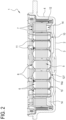
- the machine 1 having an axis of rotation R, comprises a casing 2 and a cap, not illustrated, for closing the casing 2.
- the casing 2 has a base wall 3 transverse to the axis of rotation R and a side wall 4, preferably cylindrical, extending from the wall 3.
- the casing 2 and the cap fit together in a direction parallel to the axis of rotation R and form a closed container, preferably of the sealed type.
- the motor 1 comprises a stator 5, integral with the casing 2, and a permanent magnet rotor, not illustrated, connected rotatably to the casing 2 and to the cap.
- the rotor comprises a shaft having at least one end which protrudes from the container formed by the casing and the cap and to which a fan of an electric ventilator may be fixed, for example.
- the stator 5 comprises a plurality of pole pieces 6 and phase conductors 7 wound around the pole pieces 6.
- phase conductors 7 wound around the pole pieces 6 define a plurality of coils 8 which, in the example illustrated, constitute the stator winding 9.
- Each coil 8 has an end portion 10, facing towards the bottom of the casing 2, and an end portion 11 which are aligned with each other in a direction parallel to the axis R.
- the machine 1 comprises a thermally conductive and electrically insulating annular heat sink 12 interposed between the stator and the base wall 3 of the casing 2.
- the annular heat sink 12 is preferably made by moulding a plastic material such as, for example, LATICONTHER_80_GR_50 or CoolPoly ® E5101 Thermally Conductive Polyphenylene Sulfide (PPS) or graphite reinforced PET, which confer the required performance in terms of electrical insulation, thermal conductivity and compression strength because, as explained below, the stator is abutted against the heat sink.
- a plastic material such as, for example, LATICONTHER_80_GR_50 or CoolPoly ® E5101 Thermally Conductive Polyphenylene Sulfide (PPS) or graphite reinforced PET, which confer the required performance in terms of electrical insulation, thermal conductivity and compression strength because, as explained below, the stator is abutted against the heat sink.
- the heat sink 12 is co-moulded with the casing 2.
- the heat sink 12 is abutted against the base wall 3 and the coils 8 are abutted against the heat sink 12 on the side opposite the wall 3.
- the annular heat sink 12 defines an abutment or stop member for the stator 5 when the stator is inserted into the casing 2.
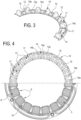
- the heat sink 12 is ring shaped and extends round the axis of rotation R of the motor 1.
- the heat sink 12 is inserted into the casing 2 coaxially with the stator 5.
- the heat sink 12 has a first face 12a directed towards the stator 5 and a second face 12b directed towards the base wall 3.
- the heat sink 12 has a radial extension substantially corresponding to the radial extension of the coils 8 in such a way that the coils 8 are abutted against the heat sink 12 for their full radial dimension so as to maximize the heat exchange surface between the stator 5 and the heat sink 12.
- the heat sink 12 is like an annular crown with substantially flat faces 12a and 12b.
- the coils are abutted against the face 12a while the face 12b is disposed against the base wall 3.
- the heat sink 12 comprises a plurality of cradles 13, each for a corresponding coil 8.
- Each cradle 13 is delimited by a pair of teeth 14 which extend from the face 12a of the heat sink 12.
- the cradles 13 follow each other, preferably uninterruptedly, along the face 12a of the heat sink 12 and each tooth 14 separates two adjacent cradles 13.
- the heat sink 12 has a plurality of teeth 14 which extend from the face 12a and each pair of teeth 14 encloses two or more coils 8; that is to say, not all the coils 8 have a respective cradle 13 or, in other words, each cradle 13 houses more than one coil 8.
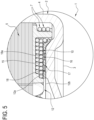
- each coil 8 is at least partly positioned in a respective cradle 13 with its end portion 10.
- Each tooth 14 has a first flank 14a and a second flank 14b.
- the first and second flanks 14a, 14b of adjacent teeth 14 delimit a respective cradle 13; the teeth 14 and cradles 13 follow each other, preferably uninterruptedly, along the face 12a of the heat sink 12.
- each cradle 13 is delimited by the flanks 14a and 14b and by a bottom portion 15.
- flanks 14a and 14b extend from the bottom portion 15 towards the stator 5 and each coil 8 is inserted at least partly between the facing flanks 14a and 14b of the respective cradle 13.
- the coils 8 are abutted against the bottom portion 15 of the respective cradle 13.
- the coils 8, more specifically at least the end portion 10 thereof, are abutted against the flanks 14a, 14b of the respective cradle 13 in such a way as to maximize the heat exchange surface between each coil 8 and the respective cradle 13.
- the machine 1 comprises a thermally conductive and electrically insulating paste 16, for example a paste of the type known as "gap filler", interposed between the coils 8 and the heat sink 12, so as to fill any empty spaces and optimize heat exchange between the coils 8 and the heat sink 12.
- a thermally conductive and electrically insulating paste 16 for example a paste of the type known as "gap filler”
- the paste 16 is also disposed between the annular heat sink 12 and the casing 2, specifically the base wall 3 thereof, in order to fill any irregularities between the coupling surfaces and to optimize heat exchange between the heat sink 12 and the casing 2.
- the heat sink 12 has a plurality of through holes 17 which, in the embodiment illustrated by way of example, are preferably located in the bottom portion 15 of each cradle 13.
- the paste 16 is usually also disposed inside the holes 17, thereby defining additional heat exchange channels, through the paste 16, to transfer heat from the stator 5 to the casing 2.
- the face 12b of the heat sink 12 is abutted against the base wall 3 of the casing 2, preferably with the paste 16 interposed between the two.
- the face of the wall 3 directed towards the inside of the casing 2 is substantially flat and, in practice, the heat sink 12 is abutted against the bottom of the casing 2 and, with its face 12b, is coplanar with the wall 3.
- the base wall 3 has a projection 18 projecting towards the inside of the casing 2.
- the projection 18 is annular and has a top face 18a in the shape of an annular crown.
- the projection 18 extends away from the positioning plane of the base wall 3 towards a space inside the motor 1.
- the heat sink 12 is abutted with its face 12b against the projection 18, specifically against the face 18a and the paste 16 is interposed between the projection 18 and the heat sink 12.
- the heat sink 12 comprises an annular tooth 19 extending from the face 12b towards the wall 3 for example for centring the heat sink 12 on the projection 18.
- the heat flows from the stator 5 to the projection 18, that is, to the casing 2 by way of the heat sink 12; the projection 18 may also be cooled by air circulating inside the motor 1.
- a method for assembling an electric machine in any of the embodiments described above comprises positioning or interposing the annular heat sink 12 between the stator 5 and the casing 2 and inserting the stator into the casing.
- the stator 5 is pushed into the casing 2 until it compresses the heat sink 12 which, in practice, constitutes an abutment member which stops further insertion of the stator into the casing.
- the heat sink 12 is inserted into the casing 2 until it abuts against the base wall 3 thereof.
- the stator 5 is then pushed into the casing 2 until it abuts against the heat sink 12.
- the heat sink 12 may be co-moulded with the casing 2 inside the base wall 3 thereof.
- the ring or heat sink 12 is coupled to the stator 5 for example by interposing the paste 16 which holds it in place.
- stator 5 and the heat sink 12 are then inserted as one and pushed into the casing 2 until the heat sink 12 abuts against the base wall 3 of the casing, thus defining for the stator 5 the abutment member which stops it from being inserted further.
- the annular heat sink 12 of the electric machine of this solution is incompressible, in the sense that it is capable, without being damaged, of withstanding the thrust by which the stator 5 is inserted into the casing 2.
- the material used is, as mentioned, sufficiently rigid to compression to remain unaffected when the stator is inserted and to constitute an abutment member for the stator when the stator is inserted into the casing.
- stator can be pressed in against the heat sink without necessitating very precise clearances for coupling stator and casing to each other, which are expensive and complicated to obtain.
- the cradles maximize the heat exchange surface between the stator winding and the heat sink, especially in combination with the paste 16 since empty spaces, if any, are filled with gap filler.
- the heat sink 12 is made as a single ring, preferably of thermally conductive plastic.
- the ring or heat sink 12 is mounted on the stator 5 and held in place by the paste 16.
- the holes 17 allow the paste to pass through and the paste can also be spread on the face 12b when the assembly made up of stator and heat sink is inserted into the casing 2; preferably, a layer of paste 16 is also applied to the heat sink 12 on the side where the casing 2 is.
Landscapes
- Engineering & Computer Science (AREA)
- Power Engineering (AREA)
- Manufacturing & Machinery (AREA)
- Physics & Mathematics (AREA)
- Thermal Sciences (AREA)
- Mechanical Engineering (AREA)
- General Engineering & Computer Science (AREA)
- Motor Or Generator Cooling System (AREA)
- Motor Or Generator Frames (AREA)
- Manufacture Of Motors, Generators (AREA)
Applications Claiming Priority (2)
| Application Number | Priority Date | Filing Date | Title |
|---|---|---|---|
| IT201700150291 | 2017-12-28 | ||
| EP18215115.9A EP3506465B1 (de) | 2017-12-28 | 2018-12-21 | Elektrische maschine |
Related Parent Applications (2)
| Application Number | Title | Priority Date | Filing Date |
|---|---|---|---|
| EP18215115.9A Division EP3506465B1 (de) | 2017-12-28 | 2018-12-21 | Elektrische maschine |
| EP18215115.9A Division-Into EP3506465B1 (de) | 2017-12-28 | 2018-12-21 | Elektrische maschine |
Publications (2)
| Publication Number | Publication Date |
|---|---|
| EP4216405A2 true EP4216405A2 (de) | 2023-07-26 |
| EP4216405A3 EP4216405A3 (de) | 2023-11-08 |
Family
ID=61731776
Family Applications (2)
| Application Number | Title | Priority Date | Filing Date |
|---|---|---|---|
| EP18215115.9A Active EP3506465B1 (de) | 2017-12-28 | 2018-12-21 | Elektrische maschine |
| EP23162113.7A Pending EP4216405A3 (de) | 2017-12-28 | 2018-12-21 | Elektrische maschine |
Family Applications Before (1)
| Application Number | Title | Priority Date | Filing Date |
|---|---|---|---|
| EP18215115.9A Active EP3506465B1 (de) | 2017-12-28 | 2018-12-21 | Elektrische maschine |
Country Status (3)
| Country | Link |
|---|---|
| US (1) | US11088597B2 (de) |
| EP (2) | EP3506465B1 (de) |
| CN (1) | CN109980855A (de) |
Families Citing this family (5)
| Publication number | Priority date | Publication date | Assignee | Title |
|---|---|---|---|---|
| EP3975384B1 (de) * | 2020-09-25 | 2024-01-17 | Etel S.A. | Spulenträger für einen rotierenden elektromotor |
| CN112737155B (zh) * | 2020-12-28 | 2022-03-01 | 安徽美芝精密制造有限公司 | 定子、电机、压缩机和制冷设备 |
| IT202100002522A1 (it) * | 2021-02-04 | 2022-08-04 | Spal Automotive Srl | Statore di macchina elettrica. |
| CN114499077B (zh) * | 2022-04-15 | 2022-06-21 | 广州市创智机电设备有限公司 | 一种新能源汽车双电机的定子组装设备 |
| KR20250008413A (ko) * | 2023-07-07 | 2025-01-14 | 삼성전자주식회사 | 모터 |
Citations (4)
| Publication number | Priority date | Publication date | Assignee | Title |
|---|---|---|---|---|
| EP0327338A2 (de) | 1988-02-03 | 1989-08-09 | Mitsubishi Denki Kabushiki Kaisha | Fahrzeug-Wechselstromgenerator und Herstellungsverfahren |
| DE8915212U1 (de) | 1989-07-08 | 1990-10-31 | Robert Bosch Gmbh, 7000 Stuttgart | Elektrische Maschine, vorzugsweise Drehstromgenerator für Kraftfahrzeuge |
| EP2282395A2 (de) | 2009-07-29 | 2011-02-09 | Joy Ride Tech. Co., Ltd. | Motoranordnung mit wärmeleitfähigem Überbrückungselement |
| WO2015015461A2 (en) | 2013-08-01 | 2015-02-05 | Spal Automotive S.R.L. | Electrical machine |
Family Cites Families (13)
| Publication number | Priority date | Publication date | Assignee | Title |
|---|---|---|---|---|
| US4451749A (en) * | 1981-09-11 | 1984-05-29 | Nippondenso Co., Ltd. | AC Generator |
| US6201321B1 (en) * | 1998-06-05 | 2001-03-13 | Bayside Controls, Inc. | Apparatus and method for dissipating heat from a motor |
| JP2000116063A (ja) * | 1998-10-05 | 2000-04-21 | Matsushita Electric Ind Co Ltd | モータ |
| BE1015766A3 (de) * | 2003-11-05 | 2005-08-02 | Atlas Copco Airpower Nv | |
| JP2008193764A (ja) * | 2007-02-01 | 2008-08-21 | Tamagawa Seiki Co Ltd | ステータ構造 |
| ITBO20070576A1 (it) * | 2007-08-07 | 2009-02-08 | Spal Automotive Srl | Macchina elettrica. |
| JP4450050B2 (ja) * | 2007-11-07 | 2010-04-14 | トヨタ自動車株式会社 | モータの冷却構造 |
| US8063547B2 (en) * | 2008-07-28 | 2011-11-22 | Kabushiki Kaisha Yaskawa Denki | Rotating electric machine and manufacturing method thereof |
| JP2013126292A (ja) * | 2011-12-14 | 2013-06-24 | Panasonic Corp | 電動機 |
| JP6194877B2 (ja) * | 2014-12-19 | 2017-09-13 | トヨタ自動車株式会社 | 回転電機 |
| JP6476384B2 (ja) * | 2015-01-20 | 2019-03-06 | 多摩川精機株式会社 | レゾルバ |
| JP5955437B1 (ja) * | 2015-04-27 | 2016-07-20 | 三菱電機株式会社 | 回転電機 |
| CN206775327U (zh) * | 2017-06-09 | 2017-12-19 | 罗寿元 | 一种电动车用自然冷却散热电机 |
-
2018
- 2018-12-20 US US16/227,035 patent/US11088597B2/en active Active
- 2018-12-21 EP EP18215115.9A patent/EP3506465B1/de active Active
- 2018-12-21 EP EP23162113.7A patent/EP4216405A3/de active Pending
- 2018-12-28 CN CN201811628505.7A patent/CN109980855A/zh active Pending
Patent Citations (4)
| Publication number | Priority date | Publication date | Assignee | Title |
|---|---|---|---|---|
| EP0327338A2 (de) | 1988-02-03 | 1989-08-09 | Mitsubishi Denki Kabushiki Kaisha | Fahrzeug-Wechselstromgenerator und Herstellungsverfahren |
| DE8915212U1 (de) | 1989-07-08 | 1990-10-31 | Robert Bosch Gmbh, 7000 Stuttgart | Elektrische Maschine, vorzugsweise Drehstromgenerator für Kraftfahrzeuge |
| EP2282395A2 (de) | 2009-07-29 | 2011-02-09 | Joy Ride Tech. Co., Ltd. | Motoranordnung mit wärmeleitfähigem Überbrückungselement |
| WO2015015461A2 (en) | 2013-08-01 | 2015-02-05 | Spal Automotive S.R.L. | Electrical machine |
Also Published As
| Publication number | Publication date |
|---|---|
| US11088597B2 (en) | 2021-08-10 |
| EP4216405A3 (de) | 2023-11-08 |
| US20190207483A1 (en) | 2019-07-04 |
| EP3506465A1 (de) | 2019-07-03 |
| EP3506465B1 (de) | 2023-05-03 |
| CN109980855A (zh) | 2019-07-05 |
Similar Documents
| Publication | Publication Date | Title |
|---|---|---|
| EP3506465B1 (de) | Elektrische maschine | |
| JP7625285B2 (ja) | 電気機械、電磁石、並びにステータを冷却する方法、ステータを製造する方法、及び電気機械を安定させる方法 | |
| CN113258704B (zh) | 线圈骨架、定子铁芯及分布绕组径向间隙型旋转电机 | |
| US11923739B1 (en) | Electric motor with bar wound stator and end turn cooling | |
| CN109478808B (zh) | 用于轴向磁通机器的定子及其生产方法 | |
| CN108604850B (zh) | 旋转电机 | |
| US20140139059A1 (en) | Rotating electric machine and related packaging method | |
| US20100244617A1 (en) | Stator having improved structure for restricting relative displacement between stator core and stator coil | |
| US20130257190A1 (en) | Ipm machine with thermally conductive compound | |
| CN111712993B (zh) | 电动马达的具有定子齿组的外部定子、每个定子齿组具有两个相邻的定子齿和连接轭 | |
| US20130069455A1 (en) | Electric machine module cooling system and method | |
| WO2013166372A1 (en) | Device and method for cooling electric device having modular stators | |
| JP2010136571A (ja) | 回転電機用ステータ | |
| KR20110103955A (ko) | 전기 기계 및 이의 고정자부의 제조 방법 | |
| JP2015177723A (ja) | 回転電機 | |
| JPH1051989A (ja) | モールド型モータ | |
| US20140132094A1 (en) | Thermal management of an ipm motor with non-magnetic bars | |
| EP4040648A1 (de) | Stator einer elektrischen maschine | |
| SI26296A (sl) | Stator s hladilnim sistemom in električni stroj z omenjenim statorjem | |
| CN115706460A (zh) | 电机及电机的加工装配方法 | |
| KR101041737B1 (ko) | 슬롯리스 영구자석 회전기기 | |
| US20230402896A1 (en) | Cooling system for high-density motor | |
| CN212343443U (zh) | 一种定子结构及电机 | |
| CN119362736A (zh) | 用于径流式马达的定子组件 | |
| CN111277057A (zh) | 一种定子结构及电机 |
Legal Events
| Date | Code | Title | Description |
|---|---|---|---|
| PUAI | Public reference made under article 153(3) epc to a published international application that has entered the european phase |
Free format text: ORIGINAL CODE: 0009012 |
|
| STAA | Information on the status of an ep patent application or granted ep patent |
Free format text: STATUS: THE APPLICATION HAS BEEN PUBLISHED |
|
| AC | Divisional application: reference to earlier application |
Ref document number: 3506465 Country of ref document: EP Kind code of ref document: P |
|
| AK | Designated contracting states |
Kind code of ref document: A2 Designated state(s): AL AT BE BG CH CY CZ DE DK EE ES FI FR GB GR HR HU IE IS IT LI LT LU LV MC MK MT NL NO PL PT RO RS SE SI SK SM TR |
|
| PUAL | Search report despatched |
Free format text: ORIGINAL CODE: 0009013 |
|
| AK | Designated contracting states |
Kind code of ref document: A3 Designated state(s): AL AT BE BG CH CY CZ DE DK EE ES FI FR GB GR HR HU IE IS IT LI LT LU LV MC MK MT NL NO PL PT RO RS SE SI SK SM TR |
|
| RIC1 | Information provided on ipc code assigned before grant |
Ipc: H02K 9/22 20060101AFI20231002BHEP |
|
| STAA | Information on the status of an ep patent application or granted ep patent |
Free format text: STATUS: REQUEST FOR EXAMINATION WAS MADE |
|
| 17P | Request for examination filed |
Effective date: 20240507 |
|
| RBV | Designated contracting states (corrected) |
Designated state(s): AL AT BE BG CH CY CZ DE DK EE ES FI FR GB GR HR HU IE IS IT LI LT LU LV MC MK MT NL NO PL PT RO RS SE SI SK SM TR |
|
| REG | Reference to a national code |
Ref country code: DE Ref legal event code: R079 Free format text: PREVIOUS MAIN CLASS: H02K0009220000 Ipc: H02K0001140000 |
|
| GRAP | Despatch of communication of intention to grant a patent |
Free format text: ORIGINAL CODE: EPIDOSNIGR1 |
|
| STAA | Information on the status of an ep patent application or granted ep patent |
Free format text: STATUS: GRANT OF PATENT IS INTENDED |
|
| RIC1 | Information provided on ipc code assigned before grant |
Ipc: H02K 1/14 20060101AFI20260313BHEP Ipc: H02K 9/22 20060101ALI20260313BHEP |