EP4216522A1 - Dispositif électronique pliable - Google Patents
Dispositif électronique pliable Download PDFInfo
- Publication number
- EP4216522A1 EP4216522A1 EP22857102.2A EP22857102A EP4216522A1 EP 4216522 A1 EP4216522 A1 EP 4216522A1 EP 22857102 A EP22857102 A EP 22857102A EP 4216522 A1 EP4216522 A1 EP 4216522A1
- Authority
- EP
- European Patent Office
- Prior art keywords
- swing arm
- pin
- boss
- connection lug
- axis
- Prior art date
- Legal status (The legal status is an assumption and is not a legal conclusion. Google has not performed a legal analysis and makes no representation as to the accuracy of the status listed.)
- Granted
Links
Images






Classifications
-
- H—ELECTRICITY
- H04—ELECTRIC COMMUNICATION TECHNIQUE
- H04M—TELEPHONIC COMMUNICATION
- H04M1/00—Substation equipment, e.g. for use by subscribers
- H04M1/02—Constructional features of telephone sets
- H04M1/0202—Portable telephone sets, e.g. cordless phones, mobile phones or bar type handsets
- H04M1/0206—Portable telephones comprising a plurality of mechanically joined movable body parts, e.g. hinged housings
- H04M1/0208—Portable telephones comprising a plurality of mechanically joined movable body parts, e.g. hinged housings characterized by the relative motions of the body parts
- H04M1/0214—Foldable telephones, i.e. with body parts pivoting to an open position around an axis parallel to the plane they define in closed position
- H04M1/0216—Foldable in one direction, i.e. using a one degree of freedom hinge
-
- G—PHYSICS
- G06—COMPUTING OR CALCULATING; COUNTING
- G06F—ELECTRIC DIGITAL DATA PROCESSING
- G06F1/00—Details not covered by groups G06F3/00 - G06F13/00 and G06F21/00
- G06F1/16—Constructional details or arrangements
- G06F1/1613—Constructional details or arrangements for portable computers
- G06F1/1615—Constructional details or arrangements for portable computers with several enclosures having relative motions, each enclosure supporting at least one I/O or computing function
- G06F1/1616—Constructional details or arrangements for portable computers with several enclosures having relative motions, each enclosure supporting at least one I/O or computing function with folding flat displays, e.g. laptop computers or notebooks having a clamshell configuration, with body parts pivoting to an open position around an axis parallel to the plane they define in closed position
-
- G—PHYSICS
- G06—COMPUTING OR CALCULATING; COUNTING
- G06F—ELECTRIC DIGITAL DATA PROCESSING
- G06F1/00—Details not covered by groups G06F3/00 - G06F13/00 and G06F21/00
- G06F1/16—Constructional details or arrangements
- G06F1/1613—Constructional details or arrangements for portable computers
- G06F1/1633—Constructional details or arrangements of portable computers not specific to the type of enclosures covered by groups G06F1/1615 - G06F1/1626
- G06F1/1637—Details related to the display arrangement, including those related to the mounting of the display in the housing
- G06F1/1641—Details related to the display arrangement, including those related to the mounting of the display in the housing the display being formed by a plurality of foldable display components
-
- G—PHYSICS
- G06—COMPUTING OR CALCULATING; COUNTING
- G06F—ELECTRIC DIGITAL DATA PROCESSING
- G06F1/00—Details not covered by groups G06F3/00 - G06F13/00 and G06F21/00
- G06F1/16—Constructional details or arrangements
- G06F1/1613—Constructional details or arrangements for portable computers
- G06F1/1633—Constructional details or arrangements of portable computers not specific to the type of enclosures covered by groups G06F1/1615 - G06F1/1626
- G06F1/1637—Details related to the display arrangement, including those related to the mounting of the display in the housing
- G06F1/1652—Details related to the display arrangement, including those related to the mounting of the display in the housing the display being flexible, e.g. mimicking a sheet of paper, or rollable
-
- G—PHYSICS
- G06—COMPUTING OR CALCULATING; COUNTING
- G06F—ELECTRIC DIGITAL DATA PROCESSING
- G06F1/00—Details not covered by groups G06F3/00 - G06F13/00 and G06F21/00
- G06F1/16—Constructional details or arrangements
- G06F1/1613—Constructional details or arrangements for portable computers
- G06F1/1633—Constructional details or arrangements of portable computers not specific to the type of enclosures covered by groups G06F1/1615 - G06F1/1626
- G06F1/1675—Miscellaneous details related to the relative movement between the different enclosures or enclosure parts
- G06F1/1681—Details related solely to hinges
-
- G—PHYSICS
- G09—EDUCATION; CRYPTOGRAPHY; DISPLAY; ADVERTISING; SEALS
- G09F—DISPLAYING; ADVERTISING; SIGNS; LABELS OR NAME-PLATES; SEALS
- G09F9/00—Indicating arrangements for variable information in which the information is built-up on a support by selection or combination of individual elements
- G09F9/30—Indicating arrangements for variable information in which the information is built-up on a support by selection or combination of individual elements in which the desired character or characters are formed by combining individual elements
- G09F9/301—Indicating arrangements for variable information in which the information is built-up on a support by selection or combination of individual elements in which the desired character or characters are formed by combining individual elements flexible foldable or roll-able electronic displays, e.g. thin LCD, OLED
-
- H—ELECTRICITY
- H04—ELECTRIC COMMUNICATION TECHNIQUE
- H04M—TELEPHONIC COMMUNICATION
- H04M1/00—Substation equipment, e.g. for use by subscribers
- H04M1/02—Constructional features of telephone sets
- H04M1/0202—Portable telephone sets, e.g. cordless phones, mobile phones or bar type handsets
- H04M1/0206—Portable telephones comprising a plurality of mechanically joined movable body parts, e.g. hinged housings
- H04M1/0208—Portable telephones comprising a plurality of mechanically joined movable body parts, e.g. hinged housings characterized by the relative motions of the body parts
- H04M1/0214—Foldable telephones, i.e. with body parts pivoting to an open position around an axis parallel to the plane they define in closed position
- H04M1/0216—Foldable in one direction, i.e. using a one degree of freedom hinge
- H04M1/022—The hinge comprising two parallel pivoting axes
-
- H—ELECTRICITY
- H04—ELECTRIC COMMUNICATION TECHNIQUE
- H04M—TELEPHONIC COMMUNICATION
- H04M1/00—Substation equipment, e.g. for use by subscribers
- H04M1/02—Constructional features of telephone sets
- H04M1/0202—Portable telephone sets, e.g. cordless phones, mobile phones or bar type handsets
- H04M1/026—Details of the structure or mounting of specific components
- H04M1/0266—Details of the structure or mounting of specific components for a display module assembly
- H04M1/0268—Details of the structure or mounting of specific components for a display module assembly including a flexible display panel
Definitions
- This application relates to the field of terminal technologies, and in particular, to a foldable electronic device.
- a mobile phone having a foldable display is unfolded and folded through a rotating shaft structure that is inside a device body.
- the rotating shaft structure of a mobile phone having a foldable display includes a shaft cover and a main swing arm.
- the main swing arm has one end in rotatable connection with the shaft cover and the other end extending toward the device body.
- the rotating shaft structure further includes a damping component and a secondary swing arm to provide some damping force so as to improve hand feel when the user folds or unfolds the device body.
- the damping component is arranged inside the shaft cover and may be a cam spring damping component, a gear damping component, or the like, which is not limited in this embodiment of this application.
- the secondary swing arm is arranged in parallel to the main swing arm, and has one end connected to the rotating shaft structure and the other end extending toward the device body. At the end close to the device body, the main swing arm is connected to the secondary swing arm through a pin. In this way, the damping force produced by the damping component can be transmitted to the main swing arm through the secondary swing arm and the pin and in turn transmitted to a middle frame and the user's hand.
- Embodiments of this application provide a foldable electronic device whose device body has more reliable damping when folded or unfolded.
- the foldable electronic device includes a shaft cover and a device body; a first swing arm connecting the shaft cover and the device body and configured to be rotatable around a first axis that is inside the shaft cover, so that the device body is folded or unfolded around the first axis; a second swing arm distributed in parallel to the first swing arm in a direction of the first axis and coupled to a damping component that is inside the shaft cover; and a pin connecting the first swing arm and the second swing arm at an end close to the device body, so that the second swing arm follows the first swing arm to rotate around a second axis that is inside the shaft cover when the first swing arm rotates and transmits a damping force produced by the damping component to the first swing arm through the pin, where the first axis is parallel to the second axis.
- the first swing arm further includes an annular groove protruding toward the second swing arm
- the second swing arm further includes a boss protruding toward the first swing arm.
- the boss is embedded into the annular groove in an axial direction of the pin, so that the boss and the annular groove bear part of the damping force when the second swing arm follows the first swing arm to rotate.
- fitting between the annular groove and the boss increases a sectional area of a joint between the first swing arm and the second swing arm and reduces shear stress experienced by the pin, avoiding fracture of the pin under an undesirably large shear stress, thereby making the device body of the electronic device have more reliable damping when folded or unfolded.
- the first swing arm is provided with a first connection lug at an end that is away from the shaft cover
- the second swing arm is provided with a second connection lug at an end that is away from the shaft cover, where the first connection lug is distributed in parallel to the second connection lug in a direction of the first axis
- the first connection lug is provided with a slide groove, where the slide groove runs through the first connection lug in the direction of the first axis
- the second connection lug is provided with a pin hole, where the pin hole runs through the second connection lug in the direction of the first axis and is located in a projection of the slide groove in the direction of the first axis
- the pin runs through the slide groove and the pin hole to make the first swing arm and the second swing arm form a pin-shaft connection.
- the first connection lug and the second connection lug can increase sizes of the first swing arm and the second swing arm at the joint, guaranteeing that the first swing arm and the second swing arm can have redundant structural strength at the joint even if the first connection lug and the second connection lug are provided with the slide groove and the pin hole for running of the pin, thus improving connection reliability.
- the first connection lug includes a first end surface facing the second connection lug, where the annular groove is arranged on the first end surface, and the slide groove is located in a region enclosed by an inner ring of the annular groove;
- the second connection lug includes a second end surface facing the first connection lug, where the boss is arranged on the second end surface, and the pin hole is located in a region enclosed by an edge of the boss; and the annular groove overlaps with the boss in thickness in an axial direction of the pin.
- the annular groove is distributed at an outer periphery of the slide groove and size of the boss is also larger than diameter of the pin hole, making the annular groove and the boss form a larger overlap area in the axial direction of the pin, facilitating transmission of the damping force between the annular groove and the boss.
- a gap between the slide groove and the pin is smaller than a gap between the inner ring of the annular groove and the boss, and the pin is configured to deform when transmitting a damping force, so as to reduce the gap between the inner ring of the annular groove and the boss, where, when the damping force transmitted by the pin is greater than a threshold, the pin deforms to make the inner ring of the annular groove contact the boss, so that the boss and the annular groove bear part of the damping force.
- the pin slightly deforms, and the slide groove contacts the pin first without the annular groove contacting the boss yet.
- the damping force produced by the damping component is transmitted to the first swing arm through the pin.
- the pin With the damping force increasing, the pin further deforms to make the gap between the inner ring of the annular groove and the boss further decrease until the annular groove and the boss contact with each other.
- the annular groove and the boss begin to bear part of the damping force, which not only reduces the shear stress experienced by the pin but also avoids further deformation of the pin, thereby avoiding fracture of the pin.
- the slide groove is a rectangular groove, and a long side of the slide groove is parallel to the first swing arm to make the pin follow the first swing arm to slide in a direction of the long side of the slide groove when the first swing arm rotates and the first axis and the second axis are not coaxial.
- the pin, the first axis, and the second axis can be distributed in a dynamically triangular manner in the process of rotation of the first swing arm and the second swing arm to avoid structural deadlock.
- the boss includes an upper edge facing the second swing arm and a lower edge facing away from the second swing arm; where the upper edge is parallel to the second swing arm; and the lower edge has an included angle with the upper edge, so that distance between the lower edge and the upper edge is reduced gradually in a direction approaching the shaft cover; where the included angle between the lower edge and the upper edge is greater than or equal to a target angle, where the target angle is a maximum value of an included angle between the first swing arm and the second swing angle when the second swing arm follows the first swing arm to rotate.
- the inner ring of the annular groove does not collide with the outer edge of the boss.
- length of the boss in a direction parallel to the second swing arm is greater than length of the boss in a direction perpendicular to the second swing arm.
- distance between the pin hole and an edge of the boss facing the shaft cover is greater than distance between the pin hole and an edge of the boss facing away from the shaft cover.
- distance between the slide groove and a short side of the first connection lug facing the shaft cover is greater than distance between the slide groove and a short side of the first connection lug facing away from the shaft cover. In this way, the pin hole is farther away from the second axis, conducive to increasing length of an arm of force of the second swing arm in transmitting a damping force, thereby reducing internal stress of the second swing arm.
- the first connection lug is a rectangular connection lug, where a long side of the first connection lug is parallel to the first swing arm, and a short side of the first connection lug is perpendicular to the first swing arm.
- the first connection lug matches the slide groove in shape, and their long sides are in parallel, helping achieve a greater grooving length of the slide groove.
- distance between the slide groove and a short side of the first connection lug facing the shaft cover is greater than distance between the slide groove and a short side of the first connection lug facing away from the shaft cover. In this way, the slide groove can be farther away from the first axis, increasing length of an arm of force of the first swing arm, thereby reducing the force experienced by the first swing arm.
- the pin includes a pin head and a pin rod, where diameter of the pin head is greater than diameter of the pin rod; the pin head is located at an end of the first connection lug facing away from the second connection lug and is in position interference with the first connection lug in a direction of an axis of the pin; and the pin rod has an end connected to the pin head and the other end extending through the slide groove and the pin hole to the outside of the second connection lug, where a cylindrical surface of the pin rod located outside the second connection lug is provided with a clamp slot, where a clamp spring is arranged inside the clamp slot, and the clamp spring forms position interference with the second connection lug in the direction of the axis of the pin.
- fitting between the pin and the clamp spring can restrict the pin from having axial displacement, preventing the pin from falling out of the slide groove and the pin hole.
- the device body includes a middle frame, where the first swing arm is connected to the middle frame. In this way, a force applied by a user for folding or unfolding the device body can be transmitted to the first swing arm through the middle frame.
- FIG. 1 is a schematic diagram of an existing mobile phone having a foldable display.
- mobile phones having a folded display may include mobile phones having an inward-folded display, mobile phones having an outward-folded display, and the like.
- a mobile phone having an inward-folded display is shown as structure a in FIG. 1
- a mobile phone having an outward-folded display is shown as structure b in FIG. 1 .
- a device body 10 of a mobile phone having an inward-folded display can be folded toward a side of the display 11, and the display 11 is hidden at an inner side of the device body 10 after the device body 10 is folded, so that the display 11 is hidden when the device body 10 is folded and is presented when the device body 10 is unfolded.
- the device body 10 of a device having an outward-folded display can be folded toward the back side of the display 11, and the display 11 surrounds the outer side of the device body 10 after the device body 10 is folded, so that the display 11 surrounds the device body 10 to form a surrounding display when the device body 10 is folded and is presented as a normal straight display when the device body 10 is unfolded.
- FIG. 1 shows a position of the rotating shaft structure 20 in a mobile phone having a foldable display.
- FIG. 2 is a local schematic diagram of a rotating shaft structure 20 of an existing mobile phone having a foldable display.
- the rotating shaft structure 20 of an existing mobile phone having a foldable display includes a shaft cover 30 and a main swing arm 40.
- the main swing arm 40 has one end in rotatable connection with the shaft cover 30 and the other end extending toward the device body 10.
- the rotating shaft structure 20 further includes a damping component (not shown in FIG. 2 ) and a secondary swing arm 50 to provide some damping force so as to improve hand feel when the user folds or unfolds the device body.
- the damping component is arranged inside the shaft cover 30 and may be a cam spring damping component, a gear damping component, or the like, which is not limited in embodiments of this application.
- the secondary swing arm 50 is arranged in parallel to the main swing arm 40, and has one end connected to the shaft cover 30 and the other end extending toward the device body 10.
- the main swing arm 40 is connected to the secondary swing arm 50 through a pin 60.
- a damping force produced by the damping component can be transmitted to the main swing arm 40 through the secondary swing arm 50 and the pin 60 and in turn transmitted to the device body 10 and a user's hand.
- the damping force is transmitted between the secondary swing arm 50 and the main swing arm 40 only through the pin 60, such that the pin 60 experiences more shear stress when being subjected to the damping force and is therefore prone to fracture.
- the transmission of the damping force between the secondary swing arm 50 and the main swing arm 40 is interrupted, making the device body 10 lose its damping characteristic.
- Embodiments of this application provide a foldable electronic device.
- the electronic device may be, for example, a mobile phone having a foldable display, a tablet, a laptop, an e-book reader, a charging case for wireless earphones, a wearable device (for example, a pair of virtual reality (VR) glasses, a smart watch, a smart bracelet, and a head mounted display device), an electronic device with a hinge structure connecting two or more parts, or electronic devices in other product forms, which is not specifically limited herein.
- the foldable electronic device according to the embodiments of this application can avoid fracture of the pin shaft between the secondary swing arm and the main swing arm under an undesirably large shear stress, allowing the device body to have more reliable damping when folded or unfolded.
- FIG. 3 is an overall schematic diagram of a foldable electronic device according to an embodiment of this application.
- FIG. 4 is a local schematic diagram of a foldable electronic device according to an embodiment of this application.
- the electronic device includes a shaft cover 30 and a device body 10 located on two sides of the shaft cover 30.
- the device body 10 of the electronic device is, on each side, connected to the shaft cover 30 through at least one first swing arm 100.
- the shaft cover 30 is a cavity structure, where a rotating shaft mechanism is arranged inside the cavity structure, the first swing arm 100 has one end in rotatable connection with the shaft cover 30 through the rotating shaft mechanism that is inside the shaft cover 30 and the other end extending toward one side of the device body 10 to be connected to the middle frame 12 of the device body 10.
- the first swing arm 100 is able to rotate around the first axis C1 that is inside the shaft cover 30, so that the device body 10 can be folded or unfolded around the first axis C1.
- each first swing arm 100 is correspondingly provided with a second swing arm 200, and the second swing arm 200 is distributed in parallel to the corresponding first swing arm 100 in a direction of the first axis C1.
- the second swing arm 200 has an end in rotatable connection with the shaft cover 30 through the rotating shaft mechanism that is inside the shaft cover 30 and the other end extending toward one side of the device body 10. In this way, the second swing arm 200 is able to rotate around a second axis C2 that is inside the shaft cover 30, where the first axis C1 is parallel to the second axis C2.
- a damping component is arranged inside the shaft cover 30, where the damping component may be a cam spring damping component, a gear damping component, or the like.
- the damping component is coupled to the second swing arm 200 to produce a damping force opposite to the rotating direction of the second swing arm 200 when the second swing arm 200 rotates around the second axis C2, where the damping force is applied on the second swing arm 200.
- the first swing arm 100 is connected to the corresponding second swing arm 200 through a pin 300.
- the first swing arm 100 connected to the device body 10 rotates around the first axis C1 under action of the force, and the second swing arm 200 follows the first swing arm 100 to rotate around the second axis C2 under action of the pin 300 connected.
- the damping force applied on the second swing arm 200 by the damping component is transmitted to the first swing arm 100 through the pin 300, then transmitted to the middle frame 12 and the device body 10 by the first swing arm 100, and finally transmitted to the user's hand, allowing the user to feel some damping and high class quality when the user folds or unfolds the device body 10.
- FIG. 5 is a sectional view of a first swing arm and a second swing arm being connected to a pin according to an embodiment of this application.
- the first swing arm 100 further includes an annular groove 110 protruding toward the second swing arm 200
- the second swing arm 200 further includes the boss 210 protruding toward the first swing arm 100 and corresponding to the annular groove 110, where the boss 210 is embedded into the annular groove 110 in an axial direction of the pin 300, meaning that the annular groove 110 overlaps with the boss 210 in thickness in the axial direction of the pin 300.
- the annular groove 110 contacts the boss 210 in a rotating direction of the first swing arm 100 and the second swing arm 200 (that is, in a direction perpendicular to an axis C3 of the pin 300).
- the damping force applied by the damping component on the second swing arm 200 can be partly transmitted to the first swing arm 100 through the boss 210 and the annular groove 110, and partly transmitted to the first swing arm 100 through the pin 300, reducing the shear stress experienced by the pin 300 at the joint between the first swing arm 100 and the second swing arm 200 when the pin 300 transmits the damping force, thereby avoid fracture of the pin 300 caused by an undesirably large shear stress.
- FIG. 5 when a user applies a force on the device body of the electronic device so as to fold or unfold the device body, a folding force applied by the user is transmitted to the first swing arm 100 through a frame of the device body.
- the second swing arm 200 experiences a damping force from the damping component, where the damping force has the same strength as but a different direction than the folding force.
- the folding force applied by the user and the damping force produced by the damping component can together produce a shear force Fs at the joint between the first swing arm 100 and the second swing arm 200, where the shear force Fs acts on the joint between the first swing arm 100 and the second swing arm 200 to make the joint experience a shear stress t.
- magnitude of the shear stress t is proportional to magnitude of the shear force Fs and is inversely proportional to the size of the sectional area a of a shearing surface.
- t is the shear stress experienced by the joint between the first swing arm 100 and the second swing arm 200
- Fs is the shear force experienced by the joint between the first swing arm 100 and the second swing arm 200
- a is a total sectional area of the joint between the first swing arm 100 and the second swing arm 200.
- the joint between the first swing arm 100 and the second swing arm 200 includes the pin 300 and the annular groove 110 and the boss 210 that contact each other.
- a1 is used to represent the sectional area of the pin 300
- a2 is used to represent the sectional area of the joint between the annular groove 110 and the boss 210.
- the embodiments of this application include an additional annular groove 110 and boss 210 at the joint between the first swing arm 100 and the second swing arm 200 to provide an additional sectional area a2 at the joint between the first swing arm 100 and the second swing arm 200, so that the sectional area of the joint between the first swing arm 100 and the second swing arm 200 increases to a1+a2 from a1. Due to increase in the sectional area, the shear stress experienced by the pin 300 decreases to t1 in the embodiments of this application from t2 in the conventional solution.
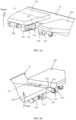
- FIG. 6a and FIG. 6b are exploded views of a first swing arm, a second swing arm, and a pin from different perspectives, according to an embodiment of this application.
- the first swing arm 100 is provided with a first connection lug 120 at an end that is away from the shaft cover 30, and the second swing arm 200 is provided with a second connection lug 220 at an end that is away from the shaft cover 30, where the first connection lug 120 is distributed in parallel to the second connection lug 220 in the direction of the first axis C1.
- the first connection lug 120 and the second connection lug 220 are arranged on the same side as the first swing arm 100 and the second swing arm 200 in a tangential direction of rotation of the first swing arm 100 and the second swing arm 200.
- the first connection lug 120 is provided with a slide groove 121, where the slide groove 121 runs through the first connection lug 120 in the direction of the first axis C1.
- the second connection lug 220 is provided with a pin hole 221 corresponding to the slide groove 121 and running through the second connection lug 220 in the direction of the first axis C1, where diameter of the pin hole 221 is equal to diameter of the pin 300 and less than size of the slide groove 121, and the pin hole 221 is located in a projection of the slide groove 121 in the direction of the first axis C1.
- the pin 300 can pass through the slide groove 121 and the pin hole 221 to make the first swing arm 100 and the second swing arm 200 form a pin-shaft connection.
- the first connection lug 120 includes a first end surface 122 facing the second connection lug 220, where the annular groove 110 is arranged on the first end surface 122, size of an inner ring of the annular groove 110 is greater than size of the slide groove 121, and the slide groove 121 is located in a region enclosed by the inner ring of the annular groove 110.
- the second connection lug 220 includes a second end surface 222 facing the first connection lug 120, where the second end surface 222 may be in parallel to and have some gap with the first end surface 122.
- the boss 210 is arranged on the second end surface 222, where size of the boss 210 is greater than diameter of the pin hole 221, and the pin hole 221 is located in a region enclosed by an edge of the boss 210.
- the sectional area of the pin 300 is typically larger than the sectional area of the annular groove 110 and the boss 210. Therefore, in the embodiments of this application, although the pin 300, the annular groove 110, and the boss 210 all play a role in transmitting the damping force and bearing the shear stress, the pin 300 can serve as a main component for transmitting the damping force and bearing the shear stress, and the annular groove 110 and the boss 210 can serve as auxiliary components for transmitting the damping force and bearing the shear stress.
- the pin 300 when a user begins to fold or unfold the device body, the pin 300 is the first to transmit the damping force and bear the shear stress between the first swing arm 100 and the second swing arm 200. As the damping force increases, the annular groove 110 and the boss 210 begin to take part to share some functions of transmitting the damping force and bearing the shear stress.
- FIG. 7 is a schematic diagram of shear stress experienced by a pin, an annular groove, and a boss changing with a damping force, according to an embodiment of this application.
- the size of the slide groove 121 is greater than the diameter of the pin 300 and the size of the inner ring of the annular groove 110 is greater than the size of the boss 210.
- a gap d1 between the slide groove 121 and the pin 300 is smaller than a gap d2 between the inner ring of the annular groove 110 and the boss 210.
- the first swing arm 100 first rotates so as to have tangential displacement relative to the pin 300 and the second swing arm 200 to make the slide groove 121 contact the pin 300, which in turn drives the second swing arm 200 to rotate.
- the gap d1 between the slide groove 121 and the pin 300 is smaller than the gap d2 between the inner ring of the annular groove 110 and the boss 210, the annular groove 110 is not in contact with the boss 210 yet, and the damping force produced by the damping component is transmitted to the first swing arm 100 through the pin 300.
- the pin 300 when the pin 300 is transmitting a damping force, the pin 300 experiences a shear force so as to deform, further increasing the tangential displacement of the first swing arm 100 relative to the second swing arm 200, so that the gap between the inner ring of the annular groove 110 and the boss 210 is reduced.
- the deformation degree of the pin 300 is related to the damping force it transmits: a greater damping force brings a greater shear force on the pin 300 and causes greater deformation.
- the damping force transmitted by the pin 300 being greater than a threshold, the deformation thereof makes the gap between the inner ring of the annular groove 110 and the boss 210 further decrease until the annular groove 110 and the boss 210 contact each other.
- the annular groove 110 and the boss 210 begin to bear part of the damping force, which not only reduces the shear stress experienced by the pin 300, but also avoids further deformation of the pin 300, thereby avoiding fracture of the pin.
- the pin 300 includes a pin head 310 and a pin rod 320, where diameter of the pin head 310 is greater than diameter of the pin rod 320; the pin head 310 is located at an end of the first connection lug 120 facing away from the second connection lug 220 and is in position interference with the first connection lug 120 in a direction of an axis C3 of the pin 300 to restrict the pin 300 from having axial displacement in the direction of the second connection lug 220; and the pin rod 320 has an end connected to the pin head 310 and the other end extending through the slide groove 121 and the pin hole to the outside of the second connection lug 220, where a cylindrical surface of the pin rod 320 located outside the second connection lug 220 is provided with a clamp slot 321, where a clamp spring 322 is arranged inside the clamp slot 321, and the clamp spring 322 forms position interference with the second connection lug 220 in the direction of the axis C3 of the pin 300 to restrict the pin 300 from having axial displacement in the direction of the second connection lug 220
- FIG. 8 is a schematic diagram of a joint between the first swing arm 100 and the second swing arm 200 in an axial direction of the pin 300 when the first axis C1 and the second axis C2 are not coaxial, according to an embodiment of this application.
- FIG. 8 displays the second connection arm 200 and the pin 300 in dotted lines. As shown in FIG.
- the pin 300, the first axis C1, and the second axis C2 are distributed in a triangular manner, which provides stability. If the distances of the pin 300 relative to the first axis C1 and the second axis C2 are always unchanged, the first swing arm 100 and the second swing arm 200 will be unable to rotate due to the locking of the triangular structure.
- the first connection lug 120 may be a rectangular connection lug, where a long side of the first connection lug 120 is parallel to the first swing arm 100, and a short side of the first connection lug 120 is perpendicular to the first swing arm 100.
- the slide groove 121 may also be a rectangular groove, where a long side of the slide groove 121 is parallel to the first swing arm 100, and a short side of the slide groove 121 is perpendicular to the first swing arm 100.
- the pin 300 when the first swing arm 100 and the second swing arm 200 rotate, the pin 300 also follows the first swing arm 100 to slide in a direction of the long side of the slide groove 121, so as to dynamically change the distance between the pin 300 and the first axis C1, making the pin 300, the first axis C1, and the second axis C2 distributed in a dynamically triangular manner during the rotation of the first swing arm 100 and the second swing arm 200, thus avoiding structural deadlock.
- distance d3 between the first axis C1 and a shaft cover bottom surface 31 is preferably greater than distance d4 between the second axis C2 and the shaft cover bottom surface 31, and the second axis C2 is closer to a side wall of the shaft cover 30 than the first axis C1.
- a wall surface of the second swing arm 200 is closer to the shaft cover 30 and farther away from the display 11 of the electronic device than a wall surface of the first swing arm 100, ensuring that the second swing arm 200 does not interfere with the first swing arm 100 supporting the display 11 during rotation.
- distance d5 between the slide groove 121 and a short side of the first connection lug 120 facing the shaft cover 30 is greater than distance d6 between the slide groove 121 and a short side of the first connection lug 120 facing away from the shaft cover 30.
- the slide groove 121 can be farther away from the first axis C1 to increase length of an arm of force of the first swing arm 100, reducing the force acting on the first swing arm 100.
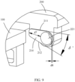
- FIG. 9 is a schematic structural diagram of a boss according to an embodiment of this application.
- the boss 210 includes an upper edge 211 facing the second swing arm 200 and a lower edge 212 facing away from the second swing arm 200.
- the upper edge 211 of the boss 210 is parallel to the second swing arm 200.
- the upper edge 211 of the boss 210 can achieve surface contact with the long side of the annular groove, facilitating transmission of the damping force between the first swing arm 100 and the second swing arm 200 so as to reduce the shear stress;
- the lower edge 212 of the boss 210 has an included angle ⁇ ' with the upper edge 211 of the boss 210, where the included angle ⁇ ' makes distance between the lower edge 212 and the upper edge 211 reduced gradually in a direction approaching the shaft cover, making the lower edge 212 of the boss 210 form a slope surface relative to the upper edge 211 of the boss 210.
- the included angle ⁇ ' between the lower edge 212 of the boss 210 and the upper edge 211 of the boss 210 is greater than or equal to a target angle, where the target angle is a maximum value of the included angle ⁇ between the first swing arm 100 and the second swing arm 200 when the second swing arm 200 follows the first swing arm 100 to rotate.
- a reason why the included angle ⁇ is formed between the first swing arm 100 and the second swing arm 200 and a method for determining the included angle ⁇ ' are specifically described in the subsequent content.
- length of the boss 210 in a direction parallel to the second swing arm 200 is greater than length of the boss 210 in a direction perpendicular to the second swing arm 200.
- Such design helps increase a contact area between the upper edge 211 of the boss 210 and the annular groove, facilitating transmission of the damping force between the first swing arm 100 and the second swing arm 200 so as to reduce the shear stress.
- distance d7 between the pin hole 221 and an edge of the boss 210 facing the shaft cover is greater than distance d8 between the pin hole 221 and an edge of the boss facing away from the shaft cover.
- the pin hole 221 is farther away from the second axis, conducive to increasing length of an arm of force of the second swing arm 200 in transmitting the damping force, thereby reducing the force experienced by the second swing arm 200.
- FIG. 10 is a schematic diagram of an included angle ⁇ between a first swing arm and a second swing arm according to an embodiment of this application.
- the reason why the included angle ⁇ is formed between the first swing arm 100 and the second swing arm 200 and the method for determining the included angle ⁇ ' are specifically described below.
- the included angle between the first swing arm 100 and the shaft cover bottom surface 31 (corresponding to the horizontal plane in FIG. 10 ) is denoted as ⁇
- the included angle between the second swing arm 200 and the shaft cover bottom surface 31 is denoted as ⁇ .
- the annular groove 110 and the boss may also have relative rotation, where an angle produced by their relative rotation is also ⁇ .
- ⁇ ' an angle produced by their relative rotation
- the inner ring of the annular groove 110 will collide with the lower edge 212 of the boss to restrict the first swing arm 100 and the second swing arm 200 from continuing to rotate, causing structural deadlock.
- the value of the included angle 6' should be greater than or equal to the maximum value of the included angle ⁇ , preferably the value of the included angle ⁇ ' being equal to the maximum value of the included angle ⁇ .
- the annular groove 110 can also contact the boss to transmit part of the damping force so as to reduce the shear stress experienced by the pin 300, thus increasing service life of the pin 300 and bearing ability of the joint between the first swing arm 100 and the second swing arm 200.
- FIG. 11 is a sketch of a motion mechanism during rotation of a first swing arm and a second swing arm according to an embodiment of this application. With reference to FIG. 11 , how the maximum value of the included angle ⁇ is determined is described below.
- sketch a displays a motion mechanism model of the device body being entirely unfolded using dotted lines and displays a motion mechanism model of the device body being folded to some angle using solid lines.
- A represents distance between an axis center of the pin and the first swing arm
- S represents distance between the axis center of the pin and the second swing arm
- ⁇ represents an included angle between the second swing arm and the horizontal plane (shaft cover bottom surface)
- ⁇ represents an included angle between the first swing arm and the horizontal plane
- D represents a projection length of the distance between the first axis and the second axis on the horizontal plane
- L1 represents the first swing arm
- ⁇ represents an included angle between the second swing arm and A
- ⁇ takes a maximum value when ⁇ takes a maximum value. Therefore, the maximum value of ⁇ can be determined so long as the maximum value of ⁇ during rotation of the first swing arm and the second swing arm is determined. From the sketched motion mechanism shown by the sketch diagram a of FIG. 11 , inference can be made that, during rotation of the device body from being entirely unfolded to being entirely folded, the included angle ⁇ exhibits a trend of increasing first and then decreasing. When a projection of a connection line D between the first axis and the second axis on a distance connection line A between the axis center of the pin and the first swing arm takes a maximum value, the included angle ⁇ reaches its maximum value, and accordingly the included angle ⁇ also reaches its maximum value.
- connection line A is parallel to the connection line D.
- fitting between the annular groove and the boss increases the sectional area of the joint between the first swing arm and the second swing arm so as to reduce the shear stress experienced by the pin, avoiding fracture of the pin under an undesirably large shear stress, thereby making the device body of the electronic device have more reliable damping when folded or unfolded.
Landscapes
- Engineering & Computer Science (AREA)
- Theoretical Computer Science (AREA)
- Computer Hardware Design (AREA)
- Physics & Mathematics (AREA)
- General Physics & Mathematics (AREA)
- Human Computer Interaction (AREA)
- General Engineering & Computer Science (AREA)
- Signal Processing (AREA)
- Mathematical Physics (AREA)
- Telephone Set Structure (AREA)
- Pivots And Pivotal Connections (AREA)
Applications Claiming Priority (2)
| Application Number | Priority Date | Filing Date | Title |
|---|---|---|---|
| CN202111449371.4A CN114244926B (zh) | 2021-11-30 | 2021-11-30 | 一种可折叠的电子设备 |
| PCT/CN2022/117010 WO2023098197A1 (fr) | 2021-11-30 | 2022-09-05 | Dispositif électronique pliable |
Publications (3)
| Publication Number | Publication Date |
|---|---|
| EP4216522A1 true EP4216522A1 (fr) | 2023-07-26 |
| EP4216522A4 EP4216522A4 (fr) | 2024-05-22 |
| EP4216522B1 EP4216522B1 (fr) | 2024-11-06 |
Family
ID=80752332
Family Applications (1)
| Application Number | Title | Priority Date | Filing Date |
|---|---|---|---|
| EP22857102.2A Active EP4216522B1 (fr) | 2021-11-30 | 2022-09-05 | Dispositif électronique pliable |
Country Status (4)
| Country | Link |
|---|---|
| US (1) | US12483641B2 (fr) |
| EP (1) | EP4216522B1 (fr) |
| CN (1) | CN114244926B (fr) |
| WO (1) | WO2023098197A1 (fr) |
Families Citing this family (4)
| Publication number | Priority date | Publication date | Assignee | Title |
|---|---|---|---|---|
| ES2983758T3 (es) * | 2020-11-20 | 2024-10-24 | Nokia Technologies Oy | Tubo de calor oscilante |
| CN114244926B (zh) | 2021-11-30 | 2022-08-26 | 荣耀终端有限公司 | 一种可折叠的电子设备 |
| CN116928200B (zh) * | 2022-03-31 | 2025-08-29 | 荣耀终端股份有限公司 | 可折叠机构和可折叠终端 |
| CN118188692B (zh) * | 2022-12-14 | 2025-11-11 | 荣耀终端股份有限公司 | 一种转动机构、支撑装置以及折叠屏终端 |
Family Cites Families (27)
| Publication number | Priority date | Publication date | Assignee | Title |
|---|---|---|---|---|
| WO2005010379A1 (fr) * | 2003-07-28 | 2005-02-03 | Fujitsu Limited | Materiel de communication radio mobile |
| US20150167052A1 (en) * | 2013-12-13 | 2015-06-18 | General Electric Company | Sample storage and extraction device for flow through elution of analytes |
| KR102414855B1 (ko) * | 2015-04-30 | 2022-07-01 | 삼성전자주식회사 | 플렉시블 전자 장치 |
| CN207053559U (zh) | 2017-01-26 | 2018-02-27 | 广东欧珀移动通信有限公司 | 壳体组件、显示装置及移动终端 |
| KR102426694B1 (ko) | 2017-05-02 | 2022-07-29 | 삼성전자주식회사 | 플렉서블 디스플레이를 포함하는 전자 장치 |
| EP3849161A4 (fr) * | 2018-09-06 | 2021-10-27 | Guangdong Oppo Mobile Telecommunications Corp., Ltd. | Terminal mobile et son extrémité hôte |
| CN113366927A (zh) * | 2019-07-15 | 2021-09-07 | 深圳市柔宇科技股份有限公司 | 折叠装置及电子设备 |
| CN110805610B (zh) * | 2019-09-29 | 2021-02-12 | 华为技术有限公司 | 一种转轴组件及电子设备 |
| KR102798666B1 (ko) * | 2019-12-13 | 2025-04-18 | 후아웨이 테크놀러지 컴퍼니 리미티드 | 회전축 구조체 및 전자 장치 |
| CN116580640A (zh) * | 2019-12-27 | 2023-08-11 | 华为技术有限公司 | 电子设备 |
| CN110891108A (zh) * | 2019-12-30 | 2020-03-17 | 上海闻泰信息技术有限公司 | 折叠屏转轴结构及折叠屏电子设备 |
| US12436560B2 (en) * | 2020-01-06 | 2025-10-07 | Microsoft Technology Licensing, Llc | Electronic device with torque-optional hinge |
| CN113534891B (zh) * | 2020-04-18 | 2024-10-18 | 华为技术有限公司 | 可折叠的电子设备 |
| KR102792939B1 (ko) * | 2020-04-29 | 2025-04-14 | 삼성디스플레이 주식회사 | 윈도우 및 이를 포함하는 표시장치 |
| CN112901643B (zh) * | 2020-09-14 | 2022-05-24 | 华为技术有限公司 | 折叠装置及电子设备 |
| WO2022119360A1 (fr) * | 2020-12-03 | 2022-06-09 | (주)파인테크닉스 | Charnière de terminal portable ayant une structure pliable |
| US20220179460A1 (en) * | 2020-12-08 | 2022-06-09 | Lepton Computing Llc | Foldable Display Device With Ratchet Mechanisms |
| JP7364774B2 (ja) * | 2021-01-05 | 2023-10-18 | サムスン エレクトロニクス カンパニー リミテッド | ヒンジ構造物を含む電子装置 |
| CN112991957A (zh) * | 2021-03-22 | 2021-06-18 | 合肥维信诺科技有限公司 | 一种折叠屏及显示设备 |
| CN115126770A (zh) * | 2021-03-24 | 2022-09-30 | 华为技术有限公司 | 一种转轴机构及终端设备 |
| CN113194183B (zh) * | 2021-05-21 | 2023-08-22 | 维沃移动通信有限公司 | 折叠机构及电子设备 |
| EP4266653B1 (fr) * | 2021-06-16 | 2025-07-16 | Samsung Electronics Co., Ltd. | Dispositif électronique pliable comprenant ensemble charnière |
| CN113643612B (zh) * | 2021-07-20 | 2023-01-24 | 江苏盈智融科技有限公司 | 内折齿轮连杆式柔性屏转轴机构 |
| KR102579762B1 (ko) * | 2021-08-24 | 2023-09-19 | 주식회사 이엠비 | 플렉서블 디스플레이패널을 이용한 폴딩식 휴대단말기의 힌지장치 |
| EP4372522A4 (fr) * | 2021-09-16 | 2024-11-13 | Samsung Electronics Co., Ltd. | Dispositif électronique comprenant une structure de charnière pour empêcher un affichage d'être endommagé |
| KR102880879B1 (ko) * | 2021-09-27 | 2025-11-04 | 삼성전자주식회사 | 힌지 어셈블리 및 이를 포함하는 전자 장치 |
| CN114244926B (zh) * | 2021-11-30 | 2022-08-26 | 荣耀终端有限公司 | 一种可折叠的电子设备 |
-
2021
- 2021-11-30 CN CN202111449371.4A patent/CN114244926B/zh active Active
-
2022
- 2022-09-05 EP EP22857102.2A patent/EP4216522B1/fr active Active
- 2022-09-05 US US18/023,505 patent/US12483641B2/en active Active
- 2022-09-05 WO PCT/CN2022/117010 patent/WO2023098197A1/fr not_active Ceased
Also Published As
| Publication number | Publication date |
|---|---|
| EP4216522B1 (fr) | 2024-11-06 |
| WO2023098197A1 (fr) | 2023-06-08 |
| EP4216522A4 (fr) | 2024-05-22 |
| US12483641B2 (en) | 2025-11-25 |
| CN114244926B (zh) | 2022-08-26 |
| US20240275871A1 (en) | 2024-08-15 |
| CN114244926A (zh) | 2022-03-25 |
Similar Documents
| Publication | Publication Date | Title |
|---|---|---|
| EP4216522B1 (fr) | Dispositif électronique pliable | |
| CN113795683B (zh) | 一种转轴机构和电子设备 | |
| EP4227546A1 (fr) | Dispositif électronique pliable | |
| WO2023197993A1 (fr) | Mécanisme de charnière et dispositif électronique | |
| CN110045788B (zh) | 折叠式电子装置 | |
| WO2023198207A1 (fr) | Mécanisme de charnière et dispositif électronique | |
| CN109973514A (zh) | 链节、铰链以及移动终端 | |
| EP4668050A1 (fr) | Arbre rotatif et dispositif électronique | |
| CN218863071U (zh) | 一种转轴机构、支撑装置和折叠屏电子设备 | |
| CN114623148B (zh) | 一种内折柔性屏移动终端的铰链 | |
| CN114263676A (zh) | 一种显示面板 | |
| WO2023109781A1 (fr) | Appareil électronique | |
| WO2024099088A1 (fr) | Mécanisme de charnière et dispositif électronique | |
| EP2615317A1 (fr) | Mécanisme d'articulation | |
| CN106325381B (zh) | 一种电子设备及其翻转机构 | |
| US12504792B2 (en) | Foldable assembly and electronic device | |
| KR102783707B1 (ko) | 벤딩 유닛, 힌지 및 플렉시블 모듈 벤딩 장치 | |
| HK40072263B (en) | Foldable electronic device | |
| HK40072263A (en) | Foldable electronic device | |
| WO2025223348A1 (fr) | Dispositif électronique | |
| CN205260601U (zh) | 一种移动终端的新型双轴铰链及移动终端 | |
| CN219953939U (zh) | 内折柔性屏移动终端的转轴及内折柔性屏移动终端 | |
| EP4545814A1 (fr) | Mécanisme d'arbre rotatif et dispositif électronique | |
| CN112102728A (zh) | 一种可折叠显示面板的支撑装置以及显示装置 | |
| EP4202241B1 (fr) | Ensemble d'amortissement, mécanisme rotatif et terminal pliable |
Legal Events
| Date | Code | Title | Description |
|---|---|---|---|
| STAA | Information on the status of an ep patent application or granted ep patent |
Free format text: STATUS: UNKNOWN |
|
| STAA | Information on the status of an ep patent application or granted ep patent |
Free format text: STATUS: THE INTERNATIONAL PUBLICATION HAS BEEN MADE |
|
| PUAI | Public reference made under article 153(3) epc to a published international application that has entered the european phase |
Free format text: ORIGINAL CODE: 0009012 |
|
| STAA | Information on the status of an ep patent application or granted ep patent |
Free format text: STATUS: REQUEST FOR EXAMINATION WAS MADE |
|
| 17P | Request for examination filed |
Effective date: 20230223 |
|
| AK | Designated contracting states |
Kind code of ref document: A1 Designated state(s): AL AT BE BG CH CY CZ DE DK EE ES FI FR GB GR HR HU IE IS IT LI LT LU LV MC MK MT NL NO PL PT RO RS SE SI SK SM TR |
|
| A4 | Supplementary search report drawn up and despatched |
Effective date: 20240423 |
|
| RIC1 | Information provided on ipc code assigned before grant |
Ipc: G06F 1/16 20060101ALI20240417BHEP Ipc: H04M 1/02 20060101AFI20240417BHEP |
|
| GRAP | Despatch of communication of intention to grant a patent |
Free format text: ORIGINAL CODE: EPIDOSNIGR1 |
|
| STAA | Information on the status of an ep patent application or granted ep patent |
Free format text: STATUS: GRANT OF PATENT IS INTENDED |
|
| INTG | Intention to grant announced |
Effective date: 20240625 |
|
| GRAS | Grant fee paid |
Free format text: ORIGINAL CODE: EPIDOSNIGR3 |
|
| GRAA | (expected) grant |
Free format text: ORIGINAL CODE: 0009210 |
|
| STAA | Information on the status of an ep patent application or granted ep patent |
Free format text: STATUS: THE PATENT HAS BEEN GRANTED |
|
| AK | Designated contracting states |
Kind code of ref document: B1 Designated state(s): AL AT BE BG CH CY CZ DE DK EE ES FI FR GB GR HR HU IE IS IT LI LT LU LV MC MK MT NL NO PL PT RO RS SE SI SK SM TR |
|
| DAV | Request for validation of the european patent (deleted) | ||
| DAX | Request for extension of the european patent (deleted) | ||
| REG | Reference to a national code |
Ref country code: GB Ref legal event code: FG4D |
|
| REG | Reference to a national code |
Ref country code: CH Ref legal event code: EP |
|
| REG | Reference to a national code |
Ref country code: DE Ref legal event code: R096 Ref document number: 602022007574 Country of ref document: DE |
|
| REG | Reference to a national code |
Ref country code: IE Ref legal event code: FG4D Ref country code: NL Ref legal event code: FP |
|
| REG | Reference to a national code |
Ref country code: LT Ref legal event code: MG9D |
|
| PG25 | Lapsed in a contracting state [announced via postgrant information from national office to epo] |
Ref country code: PT Free format text: LAPSE BECAUSE OF FAILURE TO SUBMIT A TRANSLATION OF THE DESCRIPTION OR TO PAY THE FEE WITHIN THE PRESCRIBED TIME-LIMIT Effective date: 20250306 Ref country code: HR Free format text: LAPSE BECAUSE OF FAILURE TO SUBMIT A TRANSLATION OF THE DESCRIPTION OR TO PAY THE FEE WITHIN THE PRESCRIBED TIME-LIMIT Effective date: 20241106 Ref country code: IS Free format text: LAPSE BECAUSE OF FAILURE TO SUBMIT A TRANSLATION OF THE DESCRIPTION OR TO PAY THE FEE WITHIN THE PRESCRIBED TIME-LIMIT Effective date: 20250306 |
|
| PG25 | Lapsed in a contracting state [announced via postgrant information from national office to epo] |
Ref country code: FI Free format text: LAPSE BECAUSE OF FAILURE TO SUBMIT A TRANSLATION OF THE DESCRIPTION OR TO PAY THE FEE WITHIN THE PRESCRIBED TIME-LIMIT Effective date: 20241106 |
|
| REG | Reference to a national code |
Ref country code: AT Ref legal event code: MK05 Ref document number: 1740657 Country of ref document: AT Kind code of ref document: T Effective date: 20241106 |
|
| PG25 | Lapsed in a contracting state [announced via postgrant information from national office to epo] |
Ref country code: BG Free format text: LAPSE BECAUSE OF FAILURE TO SUBMIT A TRANSLATION OF THE DESCRIPTION OR TO PAY THE FEE WITHIN THE PRESCRIBED TIME-LIMIT Effective date: 20241106 |
|
| PG25 | Lapsed in a contracting state [announced via postgrant information from national office to epo] |
Ref country code: ES Free format text: LAPSE BECAUSE OF FAILURE TO SUBMIT A TRANSLATION OF THE DESCRIPTION OR TO PAY THE FEE WITHIN THE PRESCRIBED TIME-LIMIT Effective date: 20241106 |
|
| PG25 | Lapsed in a contracting state [announced via postgrant information from national office to epo] |
Ref country code: NO Free format text: LAPSE BECAUSE OF FAILURE TO SUBMIT A TRANSLATION OF THE DESCRIPTION OR TO PAY THE FEE WITHIN THE PRESCRIBED TIME-LIMIT Effective date: 20250206 |
|
| PG25 | Lapsed in a contracting state [announced via postgrant information from national office to epo] |
Ref country code: LV Free format text: LAPSE BECAUSE OF FAILURE TO SUBMIT A TRANSLATION OF THE DESCRIPTION OR TO PAY THE FEE WITHIN THE PRESCRIBED TIME-LIMIT Effective date: 20241106 Ref country code: GR Free format text: LAPSE BECAUSE OF FAILURE TO SUBMIT A TRANSLATION OF THE DESCRIPTION OR TO PAY THE FEE WITHIN THE PRESCRIBED TIME-LIMIT Effective date: 20250207 Ref country code: AT Free format text: LAPSE BECAUSE OF FAILURE TO SUBMIT A TRANSLATION OF THE DESCRIPTION OR TO PAY THE FEE WITHIN THE PRESCRIBED TIME-LIMIT Effective date: 20241106 |
|
| PG25 | Lapsed in a contracting state [announced via postgrant information from national office to epo] |
Ref country code: PL Free format text: LAPSE BECAUSE OF FAILURE TO SUBMIT A TRANSLATION OF THE DESCRIPTION OR TO PAY THE FEE WITHIN THE PRESCRIBED TIME-LIMIT Effective date: 20241106 |
|
| PG25 | Lapsed in a contracting state [announced via postgrant information from national office to epo] |
Ref country code: RS Free format text: LAPSE BECAUSE OF FAILURE TO SUBMIT A TRANSLATION OF THE DESCRIPTION OR TO PAY THE FEE WITHIN THE PRESCRIBED TIME-LIMIT Effective date: 20250206 |
|
| PG25 | Lapsed in a contracting state [announced via postgrant information from national office to epo] |
Ref country code: SM Free format text: LAPSE BECAUSE OF FAILURE TO SUBMIT A TRANSLATION OF THE DESCRIPTION OR TO PAY THE FEE WITHIN THE PRESCRIBED TIME-LIMIT Effective date: 20241106 |
|
| PG25 | Lapsed in a contracting state [announced via postgrant information from national office to epo] |
Ref country code: DK Free format text: LAPSE BECAUSE OF FAILURE TO SUBMIT A TRANSLATION OF THE DESCRIPTION OR TO PAY THE FEE WITHIN THE PRESCRIBED TIME-LIMIT Effective date: 20241106 |
|
| PG25 | Lapsed in a contracting state [announced via postgrant information from national office to epo] |
Ref country code: EE Free format text: LAPSE BECAUSE OF FAILURE TO SUBMIT A TRANSLATION OF THE DESCRIPTION OR TO PAY THE FEE WITHIN THE PRESCRIBED TIME-LIMIT Effective date: 20241106 |
|
| PG25 | Lapsed in a contracting state [announced via postgrant information from national office to epo] |
Ref country code: RO Free format text: LAPSE BECAUSE OF FAILURE TO SUBMIT A TRANSLATION OF THE DESCRIPTION OR TO PAY THE FEE WITHIN THE PRESCRIBED TIME-LIMIT Effective date: 20241106 |
|
| PG25 | Lapsed in a contracting state [announced via postgrant information from national office to epo] |
Ref country code: SK Free format text: LAPSE BECAUSE OF FAILURE TO SUBMIT A TRANSLATION OF THE DESCRIPTION OR TO PAY THE FEE WITHIN THE PRESCRIBED TIME-LIMIT Effective date: 20241106 |
|
| PG25 | Lapsed in a contracting state [announced via postgrant information from national office to epo] |
Ref country code: CZ Free format text: LAPSE BECAUSE OF FAILURE TO SUBMIT A TRANSLATION OF THE DESCRIPTION OR TO PAY THE FEE WITHIN THE PRESCRIBED TIME-LIMIT Effective date: 20241106 |
|
| PG25 | Lapsed in a contracting state [announced via postgrant information from national office to epo] |
Ref country code: IT Free format text: LAPSE BECAUSE OF FAILURE TO SUBMIT A TRANSLATION OF THE DESCRIPTION OR TO PAY THE FEE WITHIN THE PRESCRIBED TIME-LIMIT Effective date: 20241106 |
|
| REG | Reference to a national code |
Ref country code: DE Ref legal event code: R097 Ref document number: 602022007574 Country of ref document: DE |
|
| PG25 | Lapsed in a contracting state [announced via postgrant information from national office to epo] |
Ref country code: SE Free format text: LAPSE BECAUSE OF FAILURE TO SUBMIT A TRANSLATION OF THE DESCRIPTION OR TO PAY THE FEE WITHIN THE PRESCRIBED TIME-LIMIT Effective date: 20241106 |
|
| PLBE | No opposition filed within time limit |
Free format text: ORIGINAL CODE: 0009261 |
|
| STAA | Information on the status of an ep patent application or granted ep patent |
Free format text: STATUS: NO OPPOSITION FILED WITHIN TIME LIMIT |
|
| PGFP | Annual fee paid to national office [announced via postgrant information from national office to epo] |
Ref country code: NL Payment date: 20250814 Year of fee payment: 4 |
|
| PGFP | Annual fee paid to national office [announced via postgrant information from national office to epo] |
Ref country code: DE Payment date: 20250730 Year of fee payment: 4 |
|
| 26N | No opposition filed |
Effective date: 20250807 |