EP4218533A1 - Endoskopgriff und antriebsvorrichtung - Google Patents
Endoskopgriff und antriebsvorrichtung Download PDFInfo
- Publication number
- EP4218533A1 EP4218533A1 EP21918839.8A EP21918839A EP4218533A1 EP 4218533 A1 EP4218533 A1 EP 4218533A1 EP 21918839 A EP21918839 A EP 21918839A EP 4218533 A1 EP4218533 A1 EP 4218533A1
- Authority
- EP
- European Patent Office
- Prior art keywords
- sliding block
- motor
- driving apparatus
- follow
- endoscope
- Prior art date
- Legal status (The legal status is an assumption and is not a legal conclusion. Google has not performed a legal analysis and makes no representation as to the accuracy of the status listed.)
- Pending
Links
Images




Classifications
-
- A—HUMAN NECESSITIES
- A61—MEDICAL OR VETERINARY SCIENCE; HYGIENE
- A61B—DIAGNOSIS; SURGERY; IDENTIFICATION
- A61B1/00—Instruments for performing medical examinations of the interior of cavities or tubes of the body by visual or photographical inspection, e.g. endoscopes; Illuminating arrangements therefor
- A61B1/00064—Constructional details of the endoscope body
- A61B1/00066—Proximal part of endoscope body, e.g. handles
-
- A—HUMAN NECESSITIES
- A61—MEDICAL OR VETERINARY SCIENCE; HYGIENE
- A61B—DIAGNOSIS; SURGERY; IDENTIFICATION
- A61B1/00—Instruments for performing medical examinations of the interior of cavities or tubes of the body by visual or photographical inspection, e.g. endoscopes; Illuminating arrangements therefor
- A61B1/00002—Operational features of endoscopes
- A61B1/00004—Operational features of endoscopes characterised by electronic signal processing
- A61B1/00006—Operational features of endoscopes characterised by electronic signal processing of control signals
-
- A—HUMAN NECESSITIES
- A61—MEDICAL OR VETERINARY SCIENCE; HYGIENE
- A61B—DIAGNOSIS; SURGERY; IDENTIFICATION
- A61B1/00—Instruments for performing medical examinations of the interior of cavities or tubes of the body by visual or photographical inspection, e.g. endoscopes; Illuminating arrangements therefor
- A61B1/00147—Holding or positioning arrangements
- A61B1/0016—Holding or positioning arrangements using motor drive units
-
- A—HUMAN NECESSITIES
- A61—MEDICAL OR VETERINARY SCIENCE; HYGIENE
- A61B—DIAGNOSIS; SURGERY; IDENTIFICATION
- A61B1/00—Instruments for performing medical examinations of the interior of cavities or tubes of the body by visual or photographical inspection, e.g. endoscopes; Illuminating arrangements therefor
- A61B1/005—Flexible endoscopes
- A61B1/0051—Flexible endoscopes with controlled bending of insertion part
- A61B1/0052—Constructional details of control elements, e.g. handles
-
- A—HUMAN NECESSITIES
- A61—MEDICAL OR VETERINARY SCIENCE; HYGIENE
- A61B—DIAGNOSIS; SURGERY; IDENTIFICATION
- A61B1/00—Instruments for performing medical examinations of the interior of cavities or tubes of the body by visual or photographical inspection, e.g. endoscopes; Illuminating arrangements therefor
- A61B1/005—Flexible endoscopes
- A61B1/0051—Flexible endoscopes with controlled bending of insertion part
- A61B1/0057—Constructional details of force transmission elements, e.g. control wires
-
- H—ELECTRICITY
- H02—GENERATION; CONVERSION OR DISTRIBUTION OF ELECTRIC POWER
- H02K—DYNAMO-ELECTRIC MACHINES
- H02K11/00—Structural association of dynamo-electric machines with electric components or with devices for shielding, monitoring or protection
- H02K11/20—Structural association of dynamo-electric machines with electric components or with devices for shielding, monitoring or protection for measuring, monitoring, testing, protecting or switching
-
- H—ELECTRICITY
- H02—GENERATION; CONVERSION OR DISTRIBUTION OF ELECTRIC POWER
- H02K—DYNAMO-ELECTRIC MACHINES
- H02K11/00—Structural association of dynamo-electric machines with electric components or with devices for shielding, monitoring or protection
- H02K11/20—Structural association of dynamo-electric machines with electric components or with devices for shielding, monitoring or protection for measuring, monitoring, testing, protecting or switching
- H02K11/21—Devices for sensing speed or position, or actuated thereby
- H02K11/22—Optical devices
-
- H—ELECTRICITY
- H02—GENERATION; CONVERSION OR DISTRIBUTION OF ELECTRIC POWER
- H02K—DYNAMO-ELECTRIC MACHINES
- H02K11/00—Structural association of dynamo-electric machines with electric components or with devices for shielding, monitoring or protection
- H02K11/20—Structural association of dynamo-electric machines with electric components or with devices for shielding, monitoring or protection for measuring, monitoring, testing, protecting or switching
- H02K11/24—Devices for sensing torque, or actuated thereby
-
- H—ELECTRICITY
- H02—GENERATION; CONVERSION OR DISTRIBUTION OF ELECTRIC POWER
- H02K—DYNAMO-ELECTRIC MACHINES
- H02K7/00—Arrangements for handling mechanical energy structurally associated with dynamo-electric machines, e.g. structural association with mechanical driving motors or auxiliary dynamo-electric machines
- H02K7/003—Couplings; Details of shafts
-
- H—ELECTRICITY
- H02—GENERATION; CONVERSION OR DISTRIBUTION OF ELECTRIC POWER
- H02K—DYNAMO-ELECTRIC MACHINES
- H02K7/00—Arrangements for handling mechanical energy structurally associated with dynamo-electric machines, e.g. structural association with mechanical driving motors or auxiliary dynamo-electric machines
- H02K7/06—Means for converting reciprocating motion into rotary motion or vice versa
-
- H—ELECTRICITY
- H02—GENERATION; CONVERSION OR DISTRIBUTION OF ELECTRIC POWER
- H02K—DYNAMO-ELECTRIC MACHINES
- H02K16/00—Machines with more than one rotor or stator
Definitions
- the present disclosure relates to the field of medical equipment, and in particular, to an endoscope handle and a driving apparatus.
- An endoscope is an apparatus that integrates an image sensor, an optical lens, an illumination source, and a precision mechanical structure.
- the endoscope may enter cavities of a human body via an oral cavity or other natural orifices and perform such operations as observation, biopsy and minimally invasive surgery on the tissues inside the human body.
- the endoscope in the related art allows a doctor to visually see a real-time internal picture of the human body, thereby improving convenience of diagnosis and treatment.
- the endoscope in the related art relies entirely on the hand operation control of the doctor, and is prone to stab the delicate inner walls of the cavities in a case of improper operation.
- a driving apparatus for an endoscope handle including:
- the driving apparatus further includes: a housing, the motor module and the force sensor being both located inside the housing, a main portion of the starting sliding block being located inside the housing, and the first coupling portion protruding from a hole reserved on the housing.
- the motor module includes a motor body and a motor bracket, the motor body being connected to the housing by means of the motor bracket; the force sensor is disposed on the motor bracket.
- the motor module includes a motor body directly and fixedly disposed on the housing, and the force sensor is disposed on a connection portion of the motor body and the housing.
- the driving apparatus further includes:
- the motor module includes at least three motors, a number of the starting sliding block is as many as and in one-to-one correspondence with the motors.
- the motor module includes four motors in one-to-one correspondence with four bending control wires, the four bending control wires being tightened and released to respectively control bending motions of the endoscope in four directions of a "cross".
- the driving apparatus further includes: a rocker communicatively connected to the controller and configured to control the tightening and releasing of the bending control wires by means of the four motors.
- a direction in which the rocker is pushed corresponds to a bending direction of the endoscope.
- an endoscope handle including the foregoing driving apparatus and further including: a driven apparatus detachably mounted on the driving apparatus, the driven apparatus including:
- the driving apparatus further includes: a guide rail disposed in parallel to a motion direction of the starting sliding block, the follow-up sliding block being disposed on the guide rail.
- the first coupling portion protrudes towards the driven apparatus
- the second coupling portion protrudes towards the driving apparatus
- a projection of the first coupling portion and a projection of the second coupling portion on a plane perpendicular to the motion direction of the follow-up sliding block at least partially overlap when the driven apparatus is mounted on the driving apparatus.
- projections of connection lines of portions, connected to the bending control wires, of the respective adjacent follow-up sliding blocks on a plane perpendicular to the bending control wires constitute a regular polygon.
- embodiments of the present disclosure may monitor, by means of a force sensor, the force applied to a bending control wire when a catheter head of an endoscope is bent, thereby preventing the endoscope from injuring the walls of the cavities of a human body, and improving the safety and use comfort of the endoscope.
- an endoscope typically acts entirely according to the hand operation of doctors in the related art.
- the action of the endoscope is lack of force feedback, while a visual feedback displayed on a screen is two-dimensional. Therefore, when there is insufficient experience, it is easy to scratch or stab the inner walls of the cavities of a human body with a sharp front end of the endoscope due to excessive penetration.
- the present disclosure provides a novel endoscope handle and a driving apparatus.
- a first embodiment of the present disclosure provides a driving apparatus for an endoscope handle and an endoscope handle based on the driving apparatus.
- a driving apparatus 1 for an endoscope handle includes:
- the transmission connection between the starting sliding block 13 and the motor shaft 111 may be performed indirectly or directly.
- the starting sliding block 13 may be mounted directly on the motor shaft 111.
- a lead screw structure may be formed with the motor shaft 111, so that the motor shaft 111 drives the starting sliding block 13 to move in a linear direction. That is, by means of the lead screw structure, it is realized that a rotational motion of the motor shaft 111 is converted into a linear motion of the starting sliding block 13.
- the driving apparatus 1 may further include a housing 12.
- the housing 12 may be configured to protect and support an internal structure of the driving apparatus 1.
- the motor module 11 and the force sensor 15 are both located inside the housing 12.
- a main portion of the starting sliding block 13 is located inside the housing 12.
- the coupling contact of the first coupling portion 131 with the follow-up sliding block 21 externally disposed aims to drive, by means of the follow-up sliding block 21, the bending control wire 22 of the endoscope to be tightened and released. Therefore, the coupling therebetween can be realized in various ways.
- the first coupling portion 131 may be connected to the follow-up sliding block 21 externally disposed in addition to the contact manner illustrated in FIGs. 1 and 2 .
- the follow-up sliding block 21 is only moved by the starting sliding block 13, and therefore it is not a component of the "driving apparatus 1" for the endoscopic handle, but a part of a "driven apparatus 2" for the endoscopic handle.
- a force sensor 15 is additionally disposed in the present disclosure.
- the force sensor is disposed on the motor module 11, and capable of monitoring the force applied to the bending control wire 22 when a catheter head of the endoscope is bent, and generating a stress signal.
- the force applied to the bending control wire 22 is transmitted in sequence through the follow-up sliding block 2, the starting sliding block 13 and a motor bracket 112, and eventually causes deformation of a sensing member of the force sensor 15. By measuring this deformation, the force applied to the bending control wire 22 may be obtained.
- the driving apparatus 1 is further provided with a controller communicatively connected to the motor module 11 and the force sensor 15 respectively and configured to adjust the output of the motor module 11 according to the stress signal fed back by the force sensor.
- the controller as an electronic element, may be integrated at any position within the housing 12 or may be separately disposed outside the housing 12 for remote control, and therefore the position of the controller is not limited in the present disclosure and is not illustrated in the drawings.
- the driving apparatus 1 may be further provided with a stop switch 16.
- the stop switch 16 is communicatively connected to the controller and disposed on a motion path of the starting sliding block 13.
- the stop switch 16 sends a stop signal to the controller when contacting the starting sliding block 13, indicating that the starting sliding block 13 has moved to the end of the stroke. Accordingly, the controller may stop the rotation of the motor after receiving the stop signal, thereby preventing the motor from being damaged by overload.
- the force sensor 15 may be disposed in various ways.
- the motor module 11 includes a motor body and a motor bracket 112.
- the motor body is mounted on the motor bracket 112.
- the motor bracket 112 is connected to the housing 12 by means of the force sensor 15.
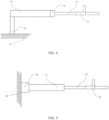
- Connection lines of the motor bracket 112, the force sensor 15 and the housing 12 in FIG. 3 are parallel to a motion direction of the starting sliding block 13, and connection lines of the motor bracket 112, the force sensor 15 and the housing 12 in FIG. 4 are perpendicular to the motion direction of the starting sliding block 13.
- the motor module 11 may include only a motor body directly connected to the housing 12 by means of the force sensor 15.
- Connection lines of the motor bracket 112, the force sensor 15 and the housing 12 in FIG. 5 are parallel to the motion direction of the starting sliding block 13, and similarly, the connection lines may be perpendicular to the motion direction.
- the force sensor 15 may detect the deformation and transmit a corresponding deformation signal to the controller. Based on the above principle, by connecting the motor module 11 to the housing 12 through the force sensor 15, the controller may accurately obtain feedback force information so as to correspondingly modify and adjust the output of the motor module 11. For example, when it is detected that the motion of the endoscope is blocked, it may be determined that the endoscope has contacted an inner surface of the human body. At this moment, the endoscope may be retracted into a safe distance through feedback and compensation operations.
- connection lines of the motor bracket 112 the force sensor 15 and the housing 12 are parallel to the motion direction of the starting sliding block 13, the feedback to the force sensor 15 is a positive pushing force or a positive pulling force.
- the connection lines of the motor bracket 112 the force sensor 15 and the housing 12 are perpendicular to the motion direction of the starting sliding block 13, the feedback to the force sensor 15 is the stress in a shear direction.
- the driving apparatus 1 may further include: a position sensor 14 disposed on the motor and configured to acquire number information of revolutions of the motor.
- the position sensor 14 is communicatively connected to the controller.
- a grating sensor may be selected as the position sensor 14. After the number information of revolutions acquired by the position sensor 14 is provided to the controller, the controller may accurately calculate a current specific position of the starting sliding block 13 accordingly, so as to provide an auxiliary reference for the compensation motion of the starting sliding block 13.
- the motor module 11 may include at least two motors.
- the motor module may include three or more motors.
- the motor module may include four motors. When there are two motors, a lens end of the endoscope may move freely in one degree of freedom, which achieves the "linear" motion of the endoscope.
- the four motors are in one-to-one correspondence with four bending control wires 22, and the four bending control wires 22 may be tightened and released to respectively control bending motions of the endoscope in four directions of a "cross".
- an inclined motion of the endoscope may be controlled.
- an inclined angle of the endoscope can also be controlled by controlling the tightening and releasing degree of the two bending control wires 22, and the precision of the motion is higher than that in the case of three motors.
- a number of the starting sliding block 13 is as many as and in one-to-one correspondence with the motors.
- Other structures including the bending control wire 22, the follow-up sliding block 21, the force sensor 15, the stop switch 16, and the position sensor 14 may also be disposed in a one-to-one correspondence.
- the controller may perform motion control and feedback compensation separately for each motor.
- the driving apparatus 1 may further include: a rocker communicatively connected to the controller and configured to control the tightening and releasing of the bending control wires 22 by means of the four motors.
- a direction in which the rocker is pushed corresponds to a bending direction of the endoscope.
- the rocker is used to control the motion of the endoscope so as to achieve the operation logic that what you see is what you get, thereby reducing the control difficulty of the endoscope, and allowing a doctor to concentrate more on medical operations.
- an embodiment of the present disclosure further provides operation steps of the driving apparatus 1 as follows:
- the embodiments of the present disclosure can effectively prevent, by means of the force sensor 15, the endoscope from injuring the human body due to excessive penetration, thereby improving the safety and use comfort of the endoscope.
- the inventors of the present disclosure have found that most endoscopes of the related art are reusable due to cost limitations. Therefore, the endoscope needs to be thoroughly disinfected and cleaned after use for each patient. The cleaning process is cumbersome and has a negative impact on the efficiency of diagnosis and treatment.
- a second embodiment of the present disclosure provides an endoscopic handle.
- the endoscopic handle in addition to the driving apparatus 1 mentioned in the first embodiment, also includes: a driven apparatus 2 detachably mounted on the driving apparatus 1.
- the driven apparatus 2 may include a follow-up sliding block 21.
- the follow-up sliding block 21 is provided with a second coupling portion 211.
- the second coupling portion 211 is in coupling contact with the first coupling portion 131 when the driven apparatus 2 is mounted on the driving apparatus 1.
- a bending control wire 22 is connected to the follow-up sliding block 21 so as to be tightened and released by the follow-up sliding block 21.
- the driven apparatus 2 may be detachable, the driven apparatus in the endoscope after each use may be discarded and replaced with a new driven apparatus 2, so that consumables contacting the body part of a patient are disposable, the convenience can be improved while the risk of cross-contamination is prevented, and the safety is improved.
- the driven apparatus 2 may further include a guide rail 23 disposed in parallel to a motion direction of the starting sliding block 13.
- the follow-up sliding block 21 is disposed on the guide rail 23.
- the present disclosure does not specifically limit the coupling relationship between the first coupling portion 131 and the second coupling portion 211. It is only necessary to ensure that the starting sliding block 13 drives the follow-up sliding block 21 to move within a satisfactory range of travel.
- the first coupling portion 131 may protrude towards the driven apparatus 2, the second coupling portion 211 protrudes towards the driving apparatus 1, and a projection of the first coupling portion 131 and a projection of the second coupling portion 211 on a plane perpendicular to the motion direction of the follow-up sliding block 21 at least partially overlap when the driven apparatus 2 is mounted on the driving apparatus 1.
- the projection overlap may ensure that the first coupling portion 131 can touch and push the second coupling portion 211 to move during the motion.
- This projection overlap may be achieved in various ways.
- the first coupling portion 131 and the second coupling portion 211 may be coupled.
- a slot may be provided on the first coupling portion 131, and the second coupling portion 211 may be inserted into the slot of the first coupling portion 131.
- the coupling portions may be connected by clamping, screwing or the like.
- the coupling between the sliding blocks may also take the form of non-connection, while the force is transmitted only by touching and pushing.
- the first coupling portion 131 is located at a position near the distal end
- the second coupling portion 211 is located at a position near the proximal end.
- the controller controls the motor to rotate so as to drive the starting sliding block 13 to move along a straight line.
- the second coupling portion 211 pushes the first coupling portion 131 to move, so that the bending control wire 22 is tightened.
- the controller controls the motor to rotate reversely, and also drives the starting sliding block 13 to return.
- the first coupling portion 131 is not in contact with the second coupling portion 211, the bending control wire 22 may automatically spring back, and the endoscope returns to an equilibrium position.
- This structure has the advantage of being simpler than the connection structure, and when the apparatus returns to an equilibrium position by automatically springing back, the damage caused by excessive travel of the reverse motion can be prevented.
- follow-up sliding blocks 21 of various shapes may be adopted in order to achieve this surrounding layout. As shown in FIG. 9 , there are two follow-up sliding blocks 21 wrapping the other two follow-up sliding blocks; or as shown in FIG. 10 , the follow-up sliding blocks are arranged in two parallel rows in a height direction; or as shown in FIG. 11 , the portions connected to the bending control wires 22 are disposed at different positions of different follow-up sliding blocks. The above-mentioned arrangements all achieve the purpose of uniformly stressing the bending control wires 22.
- first member and/or a second member may represent the following three cases: only the first member exists, both the first member and the second member exist, and only the second member exists.
- character "/" herein generally represents an "or" relationship between the associated objects.
- first, second, third, etc. may be used in the examples of the present disclosure to describe certain members, these members should not be limited to only these terms. These terms are only used to distinguish one member from another. For example, a first certain member may also be referred to as a second certain member, and similarly, a second certain member may also be referred to as a first certain member, without departing from the scope of the examples of the present disclosure.
- the words “if” and “supposing”, as used herein, may be interpreted as “during” or “when” or “in response to determining” or “in response to monitoring”.
- the phrase “if determined” or “if monitored (stated condition or event)” may be interpreted as “when determined” or “in response to determining” or “when monitored (stated condition or event)” or “in response to monitoring (stated condition or event)”.
- the terms "substantially equal to”, “substantially perpendicular to”, “substantially symmetrical” and the like mean that the macroscopic sizes or relative positional relationship between two features referred to is very close to the "and" relationship.
- the positional relationship of objects is difficult to be exactly constrained at a small scale or even at a microscopic angle. Therefore, even if there is a slight error in the size and positional relationship therebetween, the achievement of the technical effect of the present disclosure will not be greatly affected.
Landscapes
- Health & Medical Sciences (AREA)
- Life Sciences & Earth Sciences (AREA)
- Engineering & Computer Science (AREA)
- Surgery (AREA)
- Biomedical Technology (AREA)
- Molecular Biology (AREA)
- Pathology (AREA)
- Radiology & Medical Imaging (AREA)
- Nuclear Medicine, Radiotherapy & Molecular Imaging (AREA)
- Biophysics (AREA)
- Physics & Mathematics (AREA)
- Heart & Thoracic Surgery (AREA)
- Medical Informatics (AREA)
- Optics & Photonics (AREA)
- Animal Behavior & Ethology (AREA)
- General Health & Medical Sciences (AREA)
- Public Health (AREA)
- Veterinary Medicine (AREA)
- Power Engineering (AREA)
- Microelectronics & Electronic Packaging (AREA)
- Signal Processing (AREA)
- Instruments For Viewing The Inside Of Hollow Bodies (AREA)
Applications Claiming Priority (2)
| Application Number | Priority Date | Filing Date | Title |
|---|---|---|---|
| CN202110035277.8A CN114391789B (zh) | 2021-01-12 | 2021-01-12 | 内窥镜手柄及驱动装置 |
| PCT/CN2021/098154 WO2022151641A1 (zh) | 2021-01-12 | 2021-06-03 | 内窥镜手柄及驱动装置 |
Publications (2)
| Publication Number | Publication Date |
|---|---|
| EP4218533A1 true EP4218533A1 (de) | 2023-08-02 |
| EP4218533A4 EP4218533A4 (de) | 2024-04-10 |
Family
ID=81225824
Family Applications (1)
| Application Number | Title | Priority Date | Filing Date |
|---|---|---|---|
| EP21918839.8A Pending EP4218533A4 (de) | 2021-01-12 | 2021-06-03 | Endoskopgriff und antriebsvorrichtung |
Country Status (4)
| Country | Link |
|---|---|
| US (1) | US20230371786A1 (de) |
| EP (1) | EP4218533A4 (de) |
| CN (1) | CN114391789B (de) |
| WO (1) | WO2022151641A1 (de) |
Families Citing this family (5)
| Publication number | Priority date | Publication date | Assignee | Title |
|---|---|---|---|---|
| WO2023055600A1 (en) * | 2021-09-30 | 2023-04-06 | Noah Medical Corporation | Systems and methods for configurable endoscope bending section |
| CN115153390B (zh) * | 2022-06-24 | 2023-12-22 | 常州朗合医疗器械有限公司 | 内窥镜及其手动式内窥镜手柄、内窥镜的操作方法 |
| CN116849580A (zh) * | 2023-06-29 | 2023-10-10 | 常州朗合医疗器械有限公司 | 手柄端连接器、手柄装置、连接装置以及内窥镜系统 |
| CN116849821A (zh) * | 2023-07-31 | 2023-10-10 | 常州朗合医疗器械有限公司 | 耗材控制装置、从属机器人及柔性导管头端弯曲度控制方法 |
| CN119157458B (zh) * | 2024-10-11 | 2025-12-26 | 珠海横乐医疗科技有限公司 | 一种基于手柄单摇杆的气管镜末端弯曲控制映射方法 |
Family Cites Families (23)
| Publication number | Priority date | Publication date | Assignee | Title |
|---|---|---|---|---|
| US8888688B2 (en) * | 2000-04-03 | 2014-11-18 | Intuitive Surgical Operations, Inc. | Connector device for a controllable instrument |
| US8034026B2 (en) * | 2001-05-18 | 2011-10-11 | Deka Products Limited Partnership | Infusion pump assembly |
| US20060144982A1 (en) * | 2004-12-31 | 2006-07-06 | Rafael Fernandez-Sein | Apparatus and method for automatic catheter threader |
| JP5121132B2 (ja) * | 2005-11-02 | 2013-01-16 | オリンパスメディカルシステムズ株式会社 | 内視鏡システム、及び内視鏡用操作補助装置 |
| JP5160549B2 (ja) * | 2007-09-11 | 2013-03-13 | オリンパス株式会社 | 内視鏡装置 |
| US8641664B2 (en) * | 2008-03-27 | 2014-02-04 | St. Jude Medical, Atrial Fibrillation Division, Inc. | Robotic catheter system with dynamic response |
| WO2010047223A1 (ja) * | 2008-10-22 | 2010-04-29 | オリンパスメディカルシステムズ株式会社 | 電動湾曲内視鏡 |
| CA2804176A1 (en) * | 2010-08-06 | 2013-02-05 | Board Of Regents Of The University Of Nebraska | Methods and systems for handling or delivering materials for natural orifice surgery |
| CN103330544B (zh) * | 2013-06-18 | 2015-01-21 | 深圳市亚泰光电技术有限公司 | 内窥镜弯曲控制机构及内窥镜 |
| JP2016016238A (ja) * | 2014-07-10 | 2016-02-01 | オリンパス株式会社 | マニピュレータ |
| CN105559735A (zh) * | 2014-11-05 | 2016-05-11 | 深圳市古安泰自动化技术有限公司 | 内窥镜 |
| CN104546036B (zh) * | 2015-02-03 | 2017-01-18 | 东南大学 | 一种腔内手术操作器 |
| DE102015204007A1 (de) * | 2015-03-05 | 2016-09-08 | Olympus Winter & Ibe Gmbh | Verfahren und Vorrichtung zur Positionsbestimmung bei einem rotatorischen Elektro-Schritt-Motor |
| WO2017019965A1 (en) * | 2015-07-29 | 2017-02-02 | Actuated Medical, Inc. | Devices for clearing blockages in artificial and natural lumens |
| CN105796043B (zh) * | 2016-03-09 | 2018-11-02 | 苏州大学 | 一种基于压力传感器信息的内窥镜机器人控制装置 |
| US9931025B1 (en) * | 2016-09-30 | 2018-04-03 | Auris Surgical Robotics, Inc. | Automated calibration of endoscopes with pull wires |
| WO2019137380A1 (zh) * | 2018-01-10 | 2019-07-18 | 北京术锐技术有限公司 | 多用途的柔性手术工具系统 |
| CN109452976B (zh) * | 2018-12-28 | 2021-01-15 | 北京术锐技术有限公司 | 一种柔性手术工具系统 |
| CN209951060U (zh) * | 2019-03-28 | 2020-01-17 | 张文丞 | 一种智能萃取饮料冷却机 |
| US11730349B2 (en) * | 2019-10-25 | 2023-08-22 | Canon U.S.A., Inc. | Steerable medical device with bending sections and improved connector therefor |
| CN110840378A (zh) * | 2019-12-05 | 2020-02-28 | 重庆金山医疗技术研究院有限公司 | 一种内窥镜用操作部和内窥镜 |
| CN111887994A (zh) * | 2020-07-16 | 2020-11-06 | 安徽航天生物科技股份有限公司 | 基于闭环反馈的软性内窥镜手术机器人系统及其控制方法 |
| CN215227404U (zh) * | 2021-01-12 | 2021-12-21 | 常州朗合医疗器械有限公司 | 内窥镜手柄及驱动装置 |
-
2021
- 2021-01-12 CN CN202110035277.8A patent/CN114391789B/zh active Active
- 2021-06-03 US US18/030,942 patent/US20230371786A1/en active Pending
- 2021-06-03 EP EP21918839.8A patent/EP4218533A4/de active Pending
- 2021-06-03 WO PCT/CN2021/098154 patent/WO2022151641A1/zh not_active Ceased
Also Published As
| Publication number | Publication date |
|---|---|
| EP4218533A4 (de) | 2024-04-10 |
| CN114391789B (zh) | 2025-01-03 |
| WO2022151641A1 (zh) | 2022-07-21 |
| CN114391789A (zh) | 2022-04-26 |
| US20230371786A1 (en) | 2023-11-23 |
Similar Documents
| Publication | Publication Date | Title |
|---|---|---|
| US20230371786A1 (en) | Endoscope handle and driving apparatus | |
| US20240138938A1 (en) | Systems and methods for instrument based insertion architectures | |
| CN108348139B (zh) | 改进的挠性机器人内窥镜系统 | |
| JP2022033697A (ja) | 操縦可能医用デバイスのための磁気コネクタ | |
| US20150011830A1 (en) | Tip actuated disposable endoscope | |
| EP3197335B1 (de) | Medizinische vorrichtungen | |
| JP5608486B2 (ja) | 手術用動力伝達アダプタ及び医療用マニピュレータシステム | |
| US20170367782A1 (en) | Instrument device manipulator with back-mounted tool attachment mechanism | |
| CN103648425A (zh) | 医疗用机械手和手术支援装置 | |
| KR20240166565A (ko) | 로봇 내시경의 반응형 삽입 및 후퇴를 위한 시스템 및 방법 | |
| CN106794048B (zh) | 操作输入装置和医疗用机械手系统 | |
| JP2008104620A (ja) | 内視鏡型手術ロボット | |
| US20220007923A1 (en) | Systems, methods, and apparatuses for capturing images during a medical procedure | |
| CN215227404U (zh) | 内窥镜手柄及驱动装置 | |
| CN115607298A (zh) | 器械输送装置、器械输送设备及介入式手术系统 | |
| US20240358448A1 (en) | Multi-unit device for robotic manipulation of elongate surgical tools | |
| CN115444562B (zh) | 机械臂装置、手术机器人及其控制方法 | |
| KR101372881B1 (ko) | 내시경 시술 훈련용 시뮬레이터의 햅틱 장치의 케이스 및 이를 구비하는 내시경 시술 훈련용 시뮬레이터의 햅틱 장치 | |
| US20070049820A1 (en) | Remotely controllable needle guide | |
| JP2013172905A (ja) | 管状挿入システム | |
| JP2020500617A (ja) | 携帯型内視鏡 | |
| KR101234523B1 (ko) | 수술용 의료 기기 | |
| CN118340581A (zh) | 一种测力手术机器人 | |
| KR20140141085A (ko) | 중재시술 로봇용 다기능 엔드이펙터 |
Legal Events
| Date | Code | Title | Description |
|---|---|---|---|
| STAA | Information on the status of an ep patent application or granted ep patent |
Free format text: STATUS: THE INTERNATIONAL PUBLICATION HAS BEEN MADE |
|
| PUAI | Public reference made under article 153(3) epc to a published international application that has entered the european phase |
Free format text: ORIGINAL CODE: 0009012 |
|
| STAA | Information on the status of an ep patent application or granted ep patent |
Free format text: STATUS: REQUEST FOR EXAMINATION WAS MADE |
|
| 17P | Request for examination filed |
Effective date: 20230331 |
|
| AK | Designated contracting states |
Kind code of ref document: A1 Designated state(s): AL AT BE BG CH CY CZ DE DK EE ES FI FR GB GR HR HU IE IS IT LI LT LU LV MC MK MT NL NO PL PT RO RS SE SI SK SM TR |
|
| A4 | Supplementary search report drawn up and despatched |
Effective date: 20240312 |
|
| RIC1 | Information provided on ipc code assigned before grant |
Ipc: H02K 16/00 20060101ALN20240305BHEP Ipc: H02K 7/00 20060101ALN20240305BHEP Ipc: H02K 11/24 20160101ALI20240305BHEP Ipc: H02K 11/20 20160101ALI20240305BHEP Ipc: H02K 7/06 20060101ALI20240305BHEP Ipc: A61B 1/00 20060101ALI20240305BHEP Ipc: A61B 1/005 20060101AFI20240305BHEP |
|
| DAV | Request for validation of the european patent (deleted) | ||
| DAX | Request for extension of the european patent (deleted) |