EP4218636B1 - Applicateur de ciment - Google Patents
Applicateur de ciment Download PDFInfo
- Publication number
- EP4218636B1 EP4218636B1 EP22154210.3A EP22154210A EP4218636B1 EP 4218636 B1 EP4218636 B1 EP 4218636B1 EP 22154210 A EP22154210 A EP 22154210A EP 4218636 B1 EP4218636 B1 EP 4218636B1
- Authority
- EP
- European Patent Office
- Prior art keywords
- cement
- bone
- prechamber
- applicator
- mixing system
- Prior art date
- Legal status (The legal status is an assumption and is not a legal conclusion. Google has not performed a legal analysis and makes no representation as to the accuracy of the status listed.)
- Active
Links
Images


Classifications
-
- A—HUMAN NECESSITIES
- A61—MEDICAL OR VETERINARY SCIENCE; HYGIENE
- A61B—DIAGNOSIS; SURGERY; IDENTIFICATION
- A61B17/00—Surgical instruments, devices or methods
- A61B17/56—Surgical instruments or methods for treatment of bones or joints; Devices specially adapted therefor
- A61B17/58—Surgical instruments or methods for treatment of bones or joints; Devices specially adapted therefor for osteosynthesis, e.g. bone plates, screws or setting implements
- A61B17/88—Osteosynthesis instruments; Methods or means for implanting or extracting internal or external fixation devices
- A61B17/8802—Equipment for handling bone cement or other fluid fillers
-
- A—HUMAN NECESSITIES
- A61—MEDICAL OR VETERINARY SCIENCE; HYGIENE
- A61B—DIAGNOSIS; SURGERY; IDENTIFICATION
- A61B17/00—Surgical instruments, devices or methods
- A61B17/56—Surgical instruments or methods for treatment of bones or joints; Devices specially adapted therefor
- A61B17/58—Surgical instruments or methods for treatment of bones or joints; Devices specially adapted therefor for osteosynthesis, e.g. bone plates, screws or setting implements
- A61B17/88—Osteosynthesis instruments; Methods or means for implanting or extracting internal or external fixation devices
- A61B17/8802—Equipment for handling bone cement or other fluid fillers
- A61B17/8805—Equipment for handling bone cement or other fluid fillers for introducing fluid filler into bone or extracting it
- A61B17/8811—Equipment for handling bone cement or other fluid fillers for introducing fluid filler into bone or extracting it characterised by the introducer tip, i.e. the part inserted into or onto the bone
-
- A—HUMAN NECESSITIES
- A61—MEDICAL OR VETERINARY SCIENCE; HYGIENE
- A61B—DIAGNOSIS; SURGERY; IDENTIFICATION
- A61B17/00—Surgical instruments, devices or methods
- A61B17/56—Surgical instruments or methods for treatment of bones or joints; Devices specially adapted therefor
- A61B17/58—Surgical instruments or methods for treatment of bones or joints; Devices specially adapted therefor for osteosynthesis, e.g. bone plates, screws or setting implements
- A61B17/88—Osteosynthesis instruments; Methods or means for implanting or extracting internal or external fixation devices
- A61B17/8802—Equipment for handling bone cement or other fluid fillers
- A61B17/8805—Equipment for handling bone cement or other fluid fillers for introducing fluid filler into bone or extracting it
- A61B17/8822—Equipment for handling bone cement or other fluid fillers for introducing fluid filler into bone or extracting it characterised by means facilitating expulsion of fluid from the introducer, e.g. a screw pump plunger, hydraulic force transmissions, application of vibrations or a vacuum
-
- A—HUMAN NECESSITIES
- A61—MEDICAL OR VETERINARY SCIENCE; HYGIENE
- A61F—FILTERS IMPLANTABLE INTO BLOOD VESSELS; PROSTHESES; DEVICES PROVIDING PATENCY TO, OR PREVENTING COLLAPSING OF, TUBULAR STRUCTURES OF THE BODY, e.g. STENTS; ORTHOPAEDIC, NURSING OR CONTRACEPTIVE DEVICES; FOMENTATION; TREATMENT OR PROTECTION OF EYES OR EARS; BANDAGES, DRESSINGS OR ABSORBENT PADS; FIRST-AID KITS
- A61F2/00—Filters implantable into blood vessels; Prostheses, i.e. artificial substitutes or replacements for parts of the body; Appliances for connecting them with the body; Devices providing patency to, or preventing collapsing of, tubular structures of the body, e.g. stents
- A61F2/02—Prostheses implantable into the body
- A61F2/30—Joints
- A61F2/32—Joints for the hip
- A61F2/36—Femoral heads ; Femoral endoprostheses
-
- A—HUMAN NECESSITIES
- A61—MEDICAL OR VETERINARY SCIENCE; HYGIENE
- A61B—DIAGNOSIS; SURGERY; IDENTIFICATION
- A61B17/00—Surgical instruments, devices or methods
- A61B17/56—Surgical instruments or methods for treatment of bones or joints; Devices specially adapted therefor
- A61B17/58—Surgical instruments or methods for treatment of bones or joints; Devices specially adapted therefor for osteosynthesis, e.g. bone plates, screws or setting implements
- A61B17/88—Osteosynthesis instruments; Methods or means for implanting or extracting internal or external fixation devices
- A61B17/8802—Equipment for handling bone cement or other fluid fillers
- A61B17/8805—Equipment for handling bone cement or other fluid fillers for introducing fluid filler into bone or extracting it
- A61B2017/8813—Discharging means for excessively introduced fluid fillers, e.g. discharging excess cement
-
- A—HUMAN NECESSITIES
- A61—MEDICAL OR VETERINARY SCIENCE; HYGIENE
- A61B—DIAGNOSIS; SURGERY; IDENTIFICATION
- A61B17/00—Surgical instruments, devices or methods
- A61B17/56—Surgical instruments or methods for treatment of bones or joints; Devices specially adapted therefor
- A61B17/58—Surgical instruments or methods for treatment of bones or joints; Devices specially adapted therefor for osteosynthesis, e.g. bone plates, screws or setting implements
- A61B17/88—Osteosynthesis instruments; Methods or means for implanting or extracting internal or external fixation devices
- A61B17/8802—Equipment for handling bone cement or other fluid fillers
- A61B17/8833—Osteosynthesis tools specially adapted for handling bone cement or fluid fillers; Means for supplying bone cement or fluid fillers to introducing tools, e.g. cartridge handling means
- A61B2017/8838—Osteosynthesis tools specially adapted for handling bone cement or fluid fillers; Means for supplying bone cement or fluid fillers to introducing tools, e.g. cartridge handling means for mixing bone cement or fluid fillers
Definitions
- the present invention relates to a cement applicator for introducing bone cement during the implantation of prostheses in bones.
- An implantation is an operation to insert an artificial material into the body.
- the material used which is also known as an implant or prosthesis, remains in the body permanently or at least for a longer period of time.
- preserving the anatomy and biomechanics is a fundamental goal of prosthetics, especially hip endoprosthetics. When treating young patients with joint replacements, it is particularly important to work as bone-preserving and minimally invasively as possible. Ultimately, preserving the bone improves the anchoring quality in the event of a subsequent replacement operation, which cannot be ruled out. More and more manufacturers are trying to meet this requirement by developing surface replacement prostheses for the treatment of bone arthrosis.
- the main task of bone cement is to anchor endoprostheses firmly and securely in the bone. Very large forces can occur on the artificial joints. In addition, the loading situation can be very complex. It is important to take into account the overlapping of pressure, shear, bending and torsional stress. The cement must be able to hold the prosthesis securely in the bone immediately after the implant is inserted and then for as many years as possible.
- Bone cement as the force-transmitting material between the prosthesis and the bone, plays a critical role in this. Air inclusions weaken the cement and promote microfractures and their spread in the cement mantle. The porosity of the bone cement can be reduced and the mechanical properties improved using vacuum mixing technology.
- bone cement consists of a powder of polymethyl methacrylate (PMMA) and a liquid of methyl methacrylate (MMA).
- PMMA and MMA are mixed in a rough ratio of 2:1, a polymethyl methacrylate bone cement is formed.
- PMMA and MMA come into contact, polymerization begins.
- the bone cement hardens and cures completely within a time interval of 7-15 minutes.
- surgeons apply bone cement early within this time interval when the bone cement is less viscous and fluid, or late within this time interval when the bone cement is more viscous and putty-like.
- cement applications are often carried out by surgeons by hand - standardization is therefore not possible and is subject only to the surgeon's expertise. Individual cement application can lead to strong fluctuations, particularly in the thickness of the cement layer on the bone during cement application - this can severely impair cement penetration into the bone and the associated stability of the implant.
- the writing US2015005778A1 discloses a cement applicator for applying a bone cement to a bone surface.
- the uniform layer thickness depends heavily on the experience of the surgeon and is not ensured by the cement applicator alone.
- the writing DE102007024083A1 discloses an alternative cement applicator. This device is used to form a cement mass applied to a bone.
- the applicator described in this document does not include any components to facilitate the application of the cement or to regulate the flow of cement. Therefore, this system cannot provide a solution to ensure a uniform layer thickness.
- the object of the present invention is to avoid the disadvantages of the prior art, so that a cement applicator can be provided for producing a particularly uniform layer of bone cement on a bone, so that a particularly reliable connection between bone and implanted prosthesis is ensured.
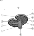
- the invention relates to an improved cement applicator 100 for applying bone cement during the implantation of prostheses.
- the cement applicator 100 is used to transfer cement from a mixing system in which the cement is located prior to use to the
- the mixing system which is not part of the actual cement applicator 100, usually comprises a bone cement syringe 1 for transferring the bone cement into a cement applicator.
- the bone cement syringe 1 normally has an opening through which the bone cement can exit from the mixing system into a cement applicator 100.
- the cement applicator 100 comprises at least one universal connection 3 for connection to a mixing system.
- This universal connection 3 is designed such that it can be connected to a mixing system so that bone cement 2 can be pressed from a mixing system through the universal connection 3.
- the diameter of the universal connection preferably has a diameter between 2 mm and 10 mm so that it is suitable for most common mixing systems.
- the universal connection is preferably designed such that the cement applicator can either be pressed on using a press fit or screwed on using an existing external thread of the nozzle screw attachment of the mixing system.
- the cement applicator 100 further comprises a prechamber 11 having a first side 11a, a second side 11b and a casing 11c which connects the first side 11a and the second side 11b to one another in a fluid-tight manner.
- the casing 11c is designed such that it encloses the interior of the prechamber 11.
- the prechamber 11 is connected on its first side 11a to the universal connector 3 in a fluid-permeable manner and serves to receive bone cement from a mixing system.
- the prechamber 11 comprises at least one exit hole 5 on the second side 11b opposite the universal connector 3.
- the prechamber 11 preferably comprises between 20 and 30 exit holes 5 with a diameter of between 1 mm and 5 mm.
- the exit holes 5 are slit-shaped with a length of 2 cm to 4 cm and a width of between 1 mm and 3 mm.
- the prechamber preferably has between 12 and 24 slit-shaped exit holes 5 through which the bone cement 2 can be pressed out of the antechamber 11.
- the cement applicator 100 comprises a guide mandrel 6. This is arranged on the second side 11b of the antechamber 11 such that it projects centrally into the antechamber 11 with a first end 6a and can be attached with an opposite second end 6b within a prepared medullary canal of a bone.
- the guide pin 6 is preferably conical with a first end 6a and is thus intended to ensure a uniform flow of the fluid into the prechamber 11. It is thus designed in such a way that it can penetrate the closure of a mixing system so that bone cement from the mixing system can reach the prechamber 11 via the universal connection 3.
- the guide pin 6 is preferably designed to allow fluid to flow through and comprises at least one outlet hole 14, so that bone cement from the mixing system can pass through the universal connector 3 through the guide pin 6 via the at least one outlet hole 14 directly into a prepared medullary canal.
- the at least one outlet hole 14 is arranged at the second end 6b.
- the guide pin preferably comprises between 10 and 20 outlet holes 14 with a size of 0.5 mm to 2 mm.
- this guide pin 6 depends on the implant and the implant size. In knee endoprostheses, this guide pin preferably has a cylindrical geometry.
- the material is preferably a printable plastic that can be sterilized at the factory and packaged sterile. This is, for example, polyetheretherketone (PEEK).
- the cement applicator 100 further comprises at least one outlet region 9. This is connected to the prechamber 11 via the second side 11b of the prechamber and is connected to the prechamber 11 via at least one outlet hole 5 in such a way that fluid can flow through it.
- the second side 11b of the prechamber 11 forms the first side 9a of the outlet region 9.
- the outlet region 9 is designed such that the side opposite the prechamber 11 is open and on a Bone 7 can be applied. Bone cement can thus be evenly applied to a bone from the antechamber 11 through the exit area 9.
- the applicator is designed so that a surgeon can remove the cement applicator 100 after cement application and press an implant into the bone cement.
- the cement applicator 100 comprises at least one torsion protection guide 8 so that it can lie flat on a bone. This is arranged between the prechamber 11 and the exit area 9.
- the torsion protection guide 8 is arranged in a spoke-like manner starting from the guide pin 6. This can either be formed as one piece with the guide pin 6 or separately.
- the torsion protection guide 8 takes on two tasks when applying the bone cement.
- the torsion protection guide is inserted into the already prepared slots in the cancellous bone during bone cement application and thus prevents the applicator from twisting about the longitudinal axis of the bone. Furthermore, no cement should get into these guides during cement application. By ensuring that the torsion protection guides fit precisely into the prepared slot, this has an additional sealing effect and thus prevents the bone cement from accidentally penetrating.
- the outlet area 9 has a seal 10 surrounding it. This is arranged so that it is located between the prechamber 11 and the outlet area 9 on the side of the casing 11c facing away from the guide pin 6.
- the seal 10 is designed as a sealing lip or sealing bead and serves to reduce the contact area between the outlet area and the bone. This ensures a constant pressure within the cement. With this uniform pressure, bone cement can be applied to any part of the bone surface at the same time.
- the cement applicator 100 comprises a pressure regulating bead 12.
- This is preferably designed as a sealing ring. It is arranged in a ring shape around the guide mandrel 6 and projects into the prechamber 11.
- the pressure regulating bead 12 can either be formed as one piece with the guide pin 6 or separately.
- the thickness of the cement mantle on the bone plateau can be influenced or adjusted in the outlet area 9 of the applicator via the seal 10 or the seal bead 12.
- the cement applicator 100 also comprises at least one stabilizing rib 13. This is arranged on the casing 11c of the prechamber and is aligned from the guide mandrel 6 to the edge of the casing 11c. It serves to increase the rigidity of the cement applicator. Alternatively, this can be achieved if the material thickness of the casing 11c is increased accordingly.
- At least one exit hole 14, seal 10, pressure regulating bead 12 and at least one stabilizing rib 13 are compatible with each other.
- each of these components can be added or omitted without affecting the function of the other components. Which component is actually used depends on the type and size of the implant for which the cement applicator is to be used.
- the cement applicator 100 To use the cement applicator 100 according to the invention, it is first plugged into the mixing system used via a universal connection 3 so that the cement 2 can be sprayed directly through it.
- the cement is first evenly distributed in the antechamber 11 by an internal guide pin 6 used for flow regulation and then comes out evenly via at least one outlet hole 5 located below. This ensures a constant pressure of the bone cement 2. With this same uniform pressure, the bone cement is introduced into the bone simultaneously and evenly.
- An implant-specific guide pin 6 and a torsion protection guide 8 within the prepared medullary canal of the bone 7 also ensure that the cement applicator 100 lies flat on the bone 7. After the cement has been applied, the surgeon can remove the cement applicator 100 and the Press the implant into the cement.
- the thickness of the cement coating on the tibial plateau can also be influenced or adjusted using a sealing ring or a sealing bead in the exit area 9 of the applicator 100. This leads to the creation of a particularly uniform layer of bone cement on a bone, thus ensuring a particularly reliable connection between a bone and an implanted prosthesis.
- the cement applicator according to the invention is basically suitable for various types of implantation in which prostheses are attached to bones using bone cement. Examples include operations to replace a hip joint, a knee joint or a shoulder joint. However, the method is not limited to this.
- the implant can consist of a wide variety of materials or material combinations. Examples of groups of materials are stainless steels, titanium compounds, ceramics or plastics. For this purpose, it is necessary to adapt the cement applicator to the respective joint geometry.
- An example design of the cement applicator is based on the geometry of the tibial component of the PFC TM SIGMAOTC3 knee system (J&J Medical Devices). After intraoperative selection of the final size, a corresponding applicator is selected that corresponds 1:1 to the geometry and size of the implant to be used - this fit is achieved by manufacturers who want to provide such an applicator for the implantation of their implants providing the 3D data.
- the cement is mixed and then the mixing system is plugged/screwed onto the cement applicator.
- the guide pin is inserted into the prepared medullary cavity. In this specific case, the torsion position is achieved using the torsion protection guide. For implants that do not have wings, any possible twisting of the implant is visually checked. Finally, the cement is pressed into the applicator by the mixing system and is evenly distributed over the prepared surface of the bone, which serves as the implant bed.
Landscapes
- Health & Medical Sciences (AREA)
- Orthopedic Medicine & Surgery (AREA)
- Life Sciences & Earth Sciences (AREA)
- Surgery (AREA)
- Public Health (AREA)
- General Health & Medical Sciences (AREA)
- Biomedical Technology (AREA)
- Heart & Thoracic Surgery (AREA)
- Engineering & Computer Science (AREA)
- Veterinary Medicine (AREA)
- Animal Behavior & Ethology (AREA)
- Medical Informatics (AREA)
- Nuclear Medicine, Radiotherapy & Molecular Imaging (AREA)
- Molecular Biology (AREA)
- Cardiology (AREA)
- Oral & Maxillofacial Surgery (AREA)
- Transplantation (AREA)
- Vascular Medicine (AREA)
- Prostheses (AREA)
Claims (5)
- applicateur de ciment (100) pour l'introduction de ciment osseux lors de l'implantation de prothèses dans l'os, comprenant au moins- un raccord universel (3) pour le raccordement à un système de mélange- une préchambre (11) constituée d'un premier côté (11a), d'un deuxième côté (11b) et d'une enveloppe (11c) qui relie le premier côté (11a) et le deuxième côté (11b) de manière étanche aux fluides,- le premier côté (11a) pouvant être relié au raccord universel (3) de manière à pouvoir être traversé par un fluide et étant adapté pour recevoir du ciment osseux provenant d'un système mixte, et- le deuxième côté (11b) étant disposé à l'opposé du premier côté (11a) et présentant au moins un trou de sortie (5) à travers lequel le ciment osseux peut sortir,- une zone de sortie (9) qui est disposée à proximité de l'antichambre (11), le deuxième côté (11b) de l'antichambre formant le premier côté (9a) de la zone de sortie (9), de sorte que la zone de sortie (9) est reliée à l'antichambre (9) de manière à pouvoir être traversée par un fluide via le au moins un trou de sortie (5), de sorte que le ciment osseux peut s'écouler de la préchambre (11) dans la zone de sortie (9), la zone de sortie (9) étant en outre conçue de telle sorte que son deuxième côté (9b) opposé à la préchambre (11) est ouvert et peut être disposé sur un os,- un guide de protection contre la torsion (8), celui-ci étant disposé entre la préchambre (11) et la chambre de sortie (9), de sorte que l'applicateur de ciment (100) peut reposer à plat sur un os.caractérisé en ce que l'applicateur de ciment (100) présente en outre un mandrin de guidage (6) qui est disposé de telle sorte qu'il pénètre avec une première extrémité (6a) dans la préchambre (11) de telle sorte qu'il puisse percer une fermeture d'un système de mélange à travers au moins un raccord universel (3), de sorte que le ciment osseux peut passer du système de mélange dans l'antichambre (11) par l'intermédiaire du raccord universel (3), une deuxième extrémité (6b) du mandrin de guidage (6), opposée à la première extrémité, pouvant être placée à l'intérieur d'un canal médullaire préparé d'un os.
- Applicateur de ciment (100) selon la revendication 1, caractérisé en ce que le mandrin de guidage (6) est conçu de manière à pouvoir être traversé par un écoulement et présente au moins un trou de sortie (14), de sorte que le ciment pour os peut parvenir du système de mélange via le raccord universel (3) à travers le mandrin de guidage (6) par le biais du au moins un trou de sortie (14) directement dans un canal médullaire préparé.
- Applicateur de ciment (100) selon la revendication 1 ou 2, caractérisé en ce que la zone de sortie (9) comporte un joint d'étanchéité (10) qui l'entoure et qui est disposé de manière à se trouver entre la préchambre (11) et la zone de sortie (9), du côté de l'enveloppe (11c) de la préchambre qui est opposé au mandrin de guidage (6).
- Applicateur de ciment (100) selon l'une des revendications précédentes, caractérisé en ce que l'applicateur de ciment (100) présente un bourrelet de régulation de pression (12) qui est disposé en forme d'anneau autour du mandrin de guidage (6) et qui fait alors saillie dans la préchambre (11).
- Applicateur de ciment (100) selon l'une des revendications précédentes, caractérisé en ce qu'il comprend encore au moins une nervure de stabilisation (13), celle-ci étant disposée sur l'enveloppe (11c) de la préchambre et étant orientée en partant du mandrin de guidage (6) vers le bord de l'enveloppe (11c).
Priority Applications (1)
| Application Number | Priority Date | Filing Date | Title |
|---|---|---|---|
| EP22154210.3A EP4218636B1 (fr) | 2022-01-31 | 2022-01-31 | Applicateur de ciment |
Applications Claiming Priority (1)
| Application Number | Priority Date | Filing Date | Title |
|---|---|---|---|
| EP22154210.3A EP4218636B1 (fr) | 2022-01-31 | 2022-01-31 | Applicateur de ciment |
Publications (2)
| Publication Number | Publication Date |
|---|---|
| EP4218636A1 EP4218636A1 (fr) | 2023-08-02 |
| EP4218636B1 true EP4218636B1 (fr) | 2024-08-14 |
Family
ID=80123318
Family Applications (1)
| Application Number | Title | Priority Date | Filing Date |
|---|---|---|---|
| EP22154210.3A Active EP4218636B1 (fr) | 2022-01-31 | 2022-01-31 | Applicateur de ciment |
Country Status (1)
| Country | Link |
|---|---|
| EP (1) | EP4218636B1 (fr) |
Family Cites Families (4)
| Publication number | Priority date | Publication date | Assignee | Title |
|---|---|---|---|---|
| DE102007024083B4 (de) | 2007-02-01 | 2018-02-01 | Rudi Georg Bitsch | Zementapplikator |
| US9855085B2 (en) | 2013-06-28 | 2018-01-02 | AOD Holdings, LLC | Bone cement applicator |
| DE102016121607B4 (de) * | 2016-11-11 | 2019-05-16 | Heraeus Medical Gmbh | Vorrichtung und Verfahren zum Lagern und Mischen eines Knochenzements |
| DE102018209784A1 (de) * | 2018-06-18 | 2019-12-19 | Heraeus Medical Gmbh | Knochenzementapplikator mit versenkbarem Mischstab und Verfahren zur Herstellung eines Knochenzements |
-
2022
- 2022-01-31 EP EP22154210.3A patent/EP4218636B1/fr active Active
Also Published As
| Publication number | Publication date |
|---|---|
| EP4218636A1 (fr) | 2023-08-02 |
Similar Documents
| Publication | Publication Date | Title |
|---|---|---|
| EP0568552B1 (fr) | Endoprothese de l'articulation de la hanche | |
| DE69527816T2 (de) | Schultergelenk-Endoprothese | |
| DE102011112890B4 (de) | Knochenschraube sowie Vorrichtung und Bausatz umfassend die Knochenschraube | |
| DE69715264T2 (de) | Knochenprothese | |
| DE2610922A1 (de) | Schaft fuer kniegelenk-endoprothesen | |
| EP0085147B1 (fr) | Tige droite plate pour une endoprothèse d'articulation | |
| DE3142730A1 (de) | "gelenkprothese" | |
| DE2220304A1 (de) | Hueftgelenkprothese, operationsverfahren zum einsetzen dieser prothese, sowie werkzeugsatz zur ausfuehrung des operationsverfahrens | |
| EP2124783A2 (fr) | Implant pour le traitement d'une fracture | |
| DD301734A9 (de) | Verankerungselement zum halten eines kuenstlichen gelenkteils | |
| DE10233204A1 (de) | Zementierbare Hüftgelenkendoprothese als Ersatz des proximalen Femur | |
| EP3923840A1 (fr) | Dispositif d'ancrage osseux pour l'abord pédiculaire | |
| EP4226897B1 (fr) | Dispositif d'augmentation | |
| CH659580A5 (de) | Den grossen trochanter ersetzendes implantat. | |
| EP3490504B1 (fr) | Implant et implant articulaire | |
| EP4218636B1 (fr) | Applicateur de ciment | |
| DE102007024083B4 (de) | Zementapplikator | |
| EP2066265B1 (fr) | Implant de hanche | |
| DE102015109353A1 (de) | Gelenkteil und Kniegelenkendoprothese | |
| EP1592369A1 (fr) | Prothese de la hanche, munie d'une tige a inserer dans le femur | |
| EP3542761B1 (fr) | Composant tibia d'une articulation artificielle du genou | |
| DE60219352T2 (de) | Set aus femurschäften, die mit einer durch ihre mitte injizierten flüssigkeit fixiert werden | |
| DE102010042082B4 (de) | Set zur Erstellung eines transkutanen Implantates | |
| EP3666229B1 (fr) | Ensemble d'endoprothèses de l'articulation du genou et instrument | |
| EP3831344A1 (fr) | Dispositif de scellage destiné à appliquer du ciment osseux |
Legal Events
| Date | Code | Title | Description |
|---|---|---|---|
| PUAI | Public reference made under article 153(3) epc to a published international application that has entered the european phase |
Free format text: ORIGINAL CODE: 0009012 |
|
| STAA | Information on the status of an ep patent application or granted ep patent |
Free format text: STATUS: THE APPLICATION HAS BEEN PUBLISHED |
|
| AK | Designated contracting states |
Kind code of ref document: A1 Designated state(s): AL AT BE BG CH CY CZ DE DK EE ES FI FR GB GR HR HU IE IS IT LI LT LU LV MC MK MT NL NO PL PT RO RS SE SI SK SM TR |
|
| STAA | Information on the status of an ep patent application or granted ep patent |
Free format text: STATUS: REQUEST FOR EXAMINATION WAS MADE |
|
| RIN1 | Information on inventor provided before grant (corrected) |
Inventor name: JAHNKE, ALEXANDER Inventor name: HARZ, TORBEN Inventor name: FONSECA-ULLOA, CARLOS ALFONSO Inventor name: FOELSCH, CHRISTIAN |
|
| 17P | Request for examination filed |
Effective date: 20240202 |
|
| RBV | Designated contracting states (corrected) |
Designated state(s): AL AT BE BG CH CY CZ DE DK EE ES FI FR GB GR HR HU IE IS IT LI LT LU LV MC MK MT NL NO PL PT RO RS SE SI SK SM TR |
|
| GRAP | Despatch of communication of intention to grant a patent |
Free format text: ORIGINAL CODE: EPIDOSNIGR1 |
|
| STAA | Information on the status of an ep patent application or granted ep patent |
Free format text: STATUS: GRANT OF PATENT IS INTENDED |
|
| RIC1 | Information provided on ipc code assigned before grant |
Ipc: A61F 2/36 20060101ALI20240221BHEP Ipc: A61B 17/88 20060101AFI20240221BHEP |
|
| INTG | Intention to grant announced |
Effective date: 20240319 |
|
| GRAS | Grant fee paid |
Free format text: ORIGINAL CODE: EPIDOSNIGR3 |
|
| GRAA | (expected) grant |
Free format text: ORIGINAL CODE: 0009210 |
|
| STAA | Information on the status of an ep patent application or granted ep patent |
Free format text: STATUS: THE PATENT HAS BEEN GRANTED |
|
| RAP3 | Party data changed (applicant data changed or rights of an application transferred) |
Owner name: JUSTUS-LIEBIG-UNIVERSITAET GIESSEN,KOERPERSCHAFT DES OEFFENTLICHEN RECHTS |
|
| AK | Designated contracting states |
Kind code of ref document: B1 Designated state(s): AL AT BE BG CH CY CZ DE DK EE ES FI FR GB GR HR HU IE IS IT LI LT LU LV MC MK MT NL NO PL PT RO RS SE SI SK SM TR |
|
| REG | Reference to a national code |
Ref country code: GB Ref legal event code: FG4D Free format text: NOT ENGLISH |
|
| REG | Reference to a national code |
Ref country code: CH Ref legal event code: EP |
|
| REG | Reference to a national code |
Ref country code: DE Ref legal event code: R096 Ref document number: 502022001424 Country of ref document: DE |
|
| REG | Reference to a national code |
Ref country code: IE Ref legal event code: FG4D Free format text: LANGUAGE OF EP DOCUMENT: GERMAN |
|
| REG | Reference to a national code |
Ref country code: LT Ref legal event code: MG9D |
|
| REG | Reference to a national code |
Ref country code: NL Ref legal event code: MP Effective date: 20240814 |
|
| PG25 | Lapsed in a contracting state [announced via postgrant information from national office to epo] |
Ref country code: NO Free format text: LAPSE BECAUSE OF FAILURE TO SUBMIT A TRANSLATION OF THE DESCRIPTION OR TO PAY THE FEE WITHIN THE PRESCRIBED TIME-LIMIT Effective date: 20241114 |
|
| PG25 | Lapsed in a contracting state [announced via postgrant information from national office to epo] |
Ref country code: PT Free format text: LAPSE BECAUSE OF FAILURE TO SUBMIT A TRANSLATION OF THE DESCRIPTION OR TO PAY THE FEE WITHIN THE PRESCRIBED TIME-LIMIT Effective date: 20241216 Ref country code: NL Free format text: LAPSE BECAUSE OF FAILURE TO SUBMIT A TRANSLATION OF THE DESCRIPTION OR TO PAY THE FEE WITHIN THE PRESCRIBED TIME-LIMIT Effective date: 20240814 Ref country code: GR Free format text: LAPSE BECAUSE OF FAILURE TO SUBMIT A TRANSLATION OF THE DESCRIPTION OR TO PAY THE FEE WITHIN THE PRESCRIBED TIME-LIMIT Effective date: 20241115 Ref country code: PL Free format text: LAPSE BECAUSE OF FAILURE TO SUBMIT A TRANSLATION OF THE DESCRIPTION OR TO PAY THE FEE WITHIN THE PRESCRIBED TIME-LIMIT Effective date: 20240814 Ref country code: FI Free format text: LAPSE BECAUSE OF FAILURE TO SUBMIT A TRANSLATION OF THE DESCRIPTION OR TO PAY THE FEE WITHIN THE PRESCRIBED TIME-LIMIT Effective date: 20240814 |
|
| PG25 | Lapsed in a contracting state [announced via postgrant information from national office to epo] |
Ref country code: BG Free format text: LAPSE BECAUSE OF FAILURE TO SUBMIT A TRANSLATION OF THE DESCRIPTION OR TO PAY THE FEE WITHIN THE PRESCRIBED TIME-LIMIT Effective date: 20240814 |
|
| PG25 | Lapsed in a contracting state [announced via postgrant information from national office to epo] |
Ref country code: LV Free format text: LAPSE BECAUSE OF FAILURE TO SUBMIT A TRANSLATION OF THE DESCRIPTION OR TO PAY THE FEE WITHIN THE PRESCRIBED TIME-LIMIT Effective date: 20240814 |
|
| PG25 | Lapsed in a contracting state [announced via postgrant information from national office to epo] |
Ref country code: IS Free format text: LAPSE BECAUSE OF FAILURE TO SUBMIT A TRANSLATION OF THE DESCRIPTION OR TO PAY THE FEE WITHIN THE PRESCRIBED TIME-LIMIT Effective date: 20241214 |
|
| PG25 | Lapsed in a contracting state [announced via postgrant information from national office to epo] |
Ref country code: HR Free format text: LAPSE BECAUSE OF FAILURE TO SUBMIT A TRANSLATION OF THE DESCRIPTION OR TO PAY THE FEE WITHIN THE PRESCRIBED TIME-LIMIT Effective date: 20240814 |
|
| PG25 | Lapsed in a contracting state [announced via postgrant information from national office to epo] |
Ref country code: RS Free format text: LAPSE BECAUSE OF FAILURE TO SUBMIT A TRANSLATION OF THE DESCRIPTION OR TO PAY THE FEE WITHIN THE PRESCRIBED TIME-LIMIT Effective date: 20241114 Ref country code: ES Free format text: LAPSE BECAUSE OF FAILURE TO SUBMIT A TRANSLATION OF THE DESCRIPTION OR TO PAY THE FEE WITHIN THE PRESCRIBED TIME-LIMIT Effective date: 20240814 |
|
| PG25 | Lapsed in a contracting state [announced via postgrant information from national office to epo] |
Ref country code: RS Free format text: LAPSE BECAUSE OF FAILURE TO SUBMIT A TRANSLATION OF THE DESCRIPTION OR TO PAY THE FEE WITHIN THE PRESCRIBED TIME-LIMIT Effective date: 20241114 Ref country code: PT Free format text: LAPSE BECAUSE OF FAILURE TO SUBMIT A TRANSLATION OF THE DESCRIPTION OR TO PAY THE FEE WITHIN THE PRESCRIBED TIME-LIMIT Effective date: 20241216 Ref country code: PL Free format text: LAPSE BECAUSE OF FAILURE TO SUBMIT A TRANSLATION OF THE DESCRIPTION OR TO PAY THE FEE WITHIN THE PRESCRIBED TIME-LIMIT Effective date: 20240814 Ref country code: NO Free format text: LAPSE BECAUSE OF FAILURE TO SUBMIT A TRANSLATION OF THE DESCRIPTION OR TO PAY THE FEE WITHIN THE PRESCRIBED TIME-LIMIT Effective date: 20241114 Ref country code: NL Free format text: LAPSE BECAUSE OF FAILURE TO SUBMIT A TRANSLATION OF THE DESCRIPTION OR TO PAY THE FEE WITHIN THE PRESCRIBED TIME-LIMIT Effective date: 20240814 Ref country code: LV Free format text: LAPSE BECAUSE OF FAILURE TO SUBMIT A TRANSLATION OF THE DESCRIPTION OR TO PAY THE FEE WITHIN THE PRESCRIBED TIME-LIMIT Effective date: 20240814 Ref country code: IS Free format text: LAPSE BECAUSE OF FAILURE TO SUBMIT A TRANSLATION OF THE DESCRIPTION OR TO PAY THE FEE WITHIN THE PRESCRIBED TIME-LIMIT Effective date: 20241214 Ref country code: HR Free format text: LAPSE BECAUSE OF FAILURE TO SUBMIT A TRANSLATION OF THE DESCRIPTION OR TO PAY THE FEE WITHIN THE PRESCRIBED TIME-LIMIT Effective date: 20240814 Ref country code: GR Free format text: LAPSE BECAUSE OF FAILURE TO SUBMIT A TRANSLATION OF THE DESCRIPTION OR TO PAY THE FEE WITHIN THE PRESCRIBED TIME-LIMIT Effective date: 20241115 Ref country code: FI Free format text: LAPSE BECAUSE OF FAILURE TO SUBMIT A TRANSLATION OF THE DESCRIPTION OR TO PAY THE FEE WITHIN THE PRESCRIBED TIME-LIMIT Effective date: 20240814 Ref country code: ES Free format text: LAPSE BECAUSE OF FAILURE TO SUBMIT A TRANSLATION OF THE DESCRIPTION OR TO PAY THE FEE WITHIN THE PRESCRIBED TIME-LIMIT Effective date: 20240814 Ref country code: BG Free format text: LAPSE BECAUSE OF FAILURE TO SUBMIT A TRANSLATION OF THE DESCRIPTION OR TO PAY THE FEE WITHIN THE PRESCRIBED TIME-LIMIT Effective date: 20240814 |
|
| PG25 | Lapsed in a contracting state [announced via postgrant information from national office to epo] |
Ref country code: RO Free format text: LAPSE BECAUSE OF FAILURE TO SUBMIT A TRANSLATION OF THE DESCRIPTION OR TO PAY THE FEE WITHIN THE PRESCRIBED TIME-LIMIT Effective date: 20240814 Ref country code: DK Free format text: LAPSE BECAUSE OF FAILURE TO SUBMIT A TRANSLATION OF THE DESCRIPTION OR TO PAY THE FEE WITHIN THE PRESCRIBED TIME-LIMIT Effective date: 20240814 Ref country code: SM Free format text: LAPSE BECAUSE OF FAILURE TO SUBMIT A TRANSLATION OF THE DESCRIPTION OR TO PAY THE FEE WITHIN THE PRESCRIBED TIME-LIMIT Effective date: 20240814 |
|
| PG25 | Lapsed in a contracting state [announced via postgrant information from national office to epo] |
Ref country code: EE Free format text: LAPSE BECAUSE OF FAILURE TO SUBMIT A TRANSLATION OF THE DESCRIPTION OR TO PAY THE FEE WITHIN THE PRESCRIBED TIME-LIMIT Effective date: 20240814 |
|
| PG25 | Lapsed in a contracting state [announced via postgrant information from national office to epo] |
Ref country code: CZ Free format text: LAPSE BECAUSE OF FAILURE TO SUBMIT A TRANSLATION OF THE DESCRIPTION OR TO PAY THE FEE WITHIN THE PRESCRIBED TIME-LIMIT Effective date: 20240814 |
|
| PG25 | Lapsed in a contracting state [announced via postgrant information from national office to epo] |
Ref country code: SK Free format text: LAPSE BECAUSE OF FAILURE TO SUBMIT A TRANSLATION OF THE DESCRIPTION OR TO PAY THE FEE WITHIN THE PRESCRIBED TIME-LIMIT Effective date: 20240814 Ref country code: IT Free format text: LAPSE BECAUSE OF FAILURE TO SUBMIT A TRANSLATION OF THE DESCRIPTION OR TO PAY THE FEE WITHIN THE PRESCRIBED TIME-LIMIT Effective date: 20240814 |
|
| REG | Reference to a national code |
Ref country code: DE Ref legal event code: R097 Ref document number: 502022001424 Country of ref document: DE |
|
| PLBE | No opposition filed within time limit |
Free format text: ORIGINAL CODE: 0009261 |
|
| STAA | Information on the status of an ep patent application or granted ep patent |
Free format text: STATUS: NO OPPOSITION FILED WITHIN TIME LIMIT |
|
| 26N | No opposition filed |
Effective date: 20250515 |
|
| REG | Reference to a national code |
Ref country code: CH Ref legal event code: PL |
|
| PG25 | Lapsed in a contracting state [announced via postgrant information from national office to epo] |
Ref country code: SE Free format text: LAPSE BECAUSE OF FAILURE TO SUBMIT A TRANSLATION OF THE DESCRIPTION OR TO PAY THE FEE WITHIN THE PRESCRIBED TIME-LIMIT Effective date: 20240814 |
|
| PG25 | Lapsed in a contracting state [announced via postgrant information from national office to epo] |
Ref country code: LU Free format text: LAPSE BECAUSE OF NON-PAYMENT OF DUE FEES Effective date: 20250131 Ref country code: MC Free format text: LAPSE BECAUSE OF FAILURE TO SUBMIT A TRANSLATION OF THE DESCRIPTION OR TO PAY THE FEE WITHIN THE PRESCRIBED TIME-LIMIT Effective date: 20240814 |
|
| PG25 | Lapsed in a contracting state [announced via postgrant information from national office to epo] |
Ref country code: BE Free format text: LAPSE BECAUSE OF NON-PAYMENT OF DUE FEES Effective date: 20250131 |
|
| PG25 | Lapsed in a contracting state [announced via postgrant information from national office to epo] |
Ref country code: FR Free format text: LAPSE BECAUSE OF NON-PAYMENT OF DUE FEES Effective date: 20250131 |
|
| PG25 | Lapsed in a contracting state [announced via postgrant information from national office to epo] |
Ref country code: CH Free format text: LAPSE BECAUSE OF NON-PAYMENT OF DUE FEES Effective date: 20250131 |
|
| REG | Reference to a national code |
Ref country code: BE Ref legal event code: MM Effective date: 20250131 |
|
| PG25 | Lapsed in a contracting state [announced via postgrant information from national office to epo] |
Ref country code: IE Free format text: LAPSE BECAUSE OF NON-PAYMENT OF DUE FEES Effective date: 20250131 |
|
| PGFP | Annual fee paid to national office [announced via postgrant information from national office to epo] |
Ref country code: DE Payment date: 20260131 Year of fee payment: 5 |
|
| PGFP | Annual fee paid to national office [announced via postgrant information from national office to epo] |
Ref country code: AT Payment date: 20260301 Year of fee payment: 5 |