EP4218865A1 - Appareil de thérapie par inhalation - Google Patents
Appareil de thérapie par inhalation Download PDFInfo
- Publication number
- EP4218865A1 EP4218865A1 EP22153887.9A EP22153887A EP4218865A1 EP 4218865 A1 EP4218865 A1 EP 4218865A1 EP 22153887 A EP22153887 A EP 22153887A EP 4218865 A1 EP4218865 A1 EP 4218865A1
- Authority
- EP
- European Patent Office
- Prior art keywords
- unit
- therapy apparatus
- inhalation therapy
- membrane
- pass filter
- Prior art date
- Legal status (The legal status is an assumption and is not a legal conclusion. Google has not performed a legal analysis and makes no representation as to the accuracy of the status listed.)
- Granted
Links
Images



Classifications
-
- A—HUMAN NECESSITIES
- A61—MEDICAL OR VETERINARY SCIENCE; HYGIENE
- A61M—DEVICES FOR INTRODUCING MEDIA INTO, OR ONTO, THE BODY; DEVICES FOR TRANSDUCING BODY MEDIA OR FOR TAKING MEDIA FROM THE BODY; DEVICES FOR PRODUCING OR ENDING SLEEP OR STUPOR
- A61M15/00—Inhalators
- A61M15/0085—Inhalators using ultrasonics
-
- A—HUMAN NECESSITIES
- A61—MEDICAL OR VETERINARY SCIENCE; HYGIENE
- A61M—DEVICES FOR INTRODUCING MEDIA INTO, OR ONTO, THE BODY; DEVICES FOR TRANSDUCING BODY MEDIA OR FOR TAKING MEDIA FROM THE BODY; DEVICES FOR PRODUCING OR ENDING SLEEP OR STUPOR
- A61M11/00—Sprayers or atomisers specially adapted for therapeutic purposes
- A61M11/005—Sprayers or atomisers specially adapted for therapeutic purposes using ultrasonics
-
- B—PERFORMING OPERATIONS; TRANSPORTING
- B06—GENERATING OR TRANSMITTING MECHANICAL VIBRATIONS IN GENERAL
- B06B—METHODS OR APPARATUS FOR GENERATING OR TRANSMITTING MECHANICAL VIBRATIONS OF INFRASONIC, SONIC, OR ULTRASONIC FREQUENCY, e.g. FOR PERFORMING MECHANICAL WORK IN GENERAL
- B06B1/00—Methods or apparatus for generating mechanical vibrations of infrasonic, sonic, or ultrasonic frequency
- B06B1/02—Methods or apparatus for generating mechanical vibrations of infrasonic, sonic, or ultrasonic frequency making use of electrical energy
- B06B1/0207—Driving circuits
- B06B1/0223—Driving circuits for generating signals continuous in time
- B06B1/0238—Driving circuits for generating signals continuous in time of a single frequency, e.g. a sine-wave
- B06B1/0246—Driving circuits for generating signals continuous in time of a single frequency, e.g. a sine-wave with a feedback signal
-
- G—PHYSICS
- G16—INFORMATION AND COMMUNICATION TECHNOLOGY [ICT] SPECIALLY ADAPTED FOR SPECIFIC APPLICATION FIELDS
- G16H—HEALTHCARE INFORMATICS, i.e. INFORMATION AND COMMUNICATION TECHNOLOGY [ICT] SPECIALLY ADAPTED FOR THE HANDLING OR PROCESSING OF MEDICAL OR HEALTHCARE DATA
- G16H20/00—ICT specially adapted for therapies or health-improving plans, e.g. for handling prescriptions, for steering therapy or for monitoring patient compliance
- G16H20/40—ICT specially adapted for therapies or health-improving plans, e.g. for handling prescriptions, for steering therapy or for monitoring patient compliance relating to mechanical, radiation or invasive therapies, e.g. surgery, laser therapy, dialysis or acupuncture
-
- G—PHYSICS
- G16—INFORMATION AND COMMUNICATION TECHNOLOGY [ICT] SPECIALLY ADAPTED FOR SPECIFIC APPLICATION FIELDS
- G16H—HEALTHCARE INFORMATICS, i.e. INFORMATION AND COMMUNICATION TECHNOLOGY [ICT] SPECIALLY ADAPTED FOR THE HANDLING OR PROCESSING OF MEDICAL OR HEALTHCARE DATA
- G16H40/00—ICT specially adapted for the management or administration of healthcare resources or facilities; ICT specially adapted for the management or operation of medical equipment or devices
- G16H40/60—ICT specially adapted for the management or administration of healthcare resources or facilities; ICT specially adapted for the management or operation of medical equipment or devices for the operation of medical equipment or devices
-
- A—HUMAN NECESSITIES
- A61—MEDICAL OR VETERINARY SCIENCE; HYGIENE
- A61M—DEVICES FOR INTRODUCING MEDIA INTO, OR ONTO, THE BODY; DEVICES FOR TRANSDUCING BODY MEDIA OR FOR TAKING MEDIA FROM THE BODY; DEVICES FOR PRODUCING OR ENDING SLEEP OR STUPOR
- A61M2205/00—General characteristics of the apparatus
- A61M2205/50—General characteristics of the apparatus with microprocessors or computers
-
- B—PERFORMING OPERATIONS; TRANSPORTING
- B05—SPRAYING OR ATOMISING IN GENERAL; APPLYING FLUENT MATERIALS TO SURFACES, IN GENERAL
- B05B—SPRAYING APPARATUS; ATOMISING APPARATUS; NOZZLES
- B05B17/00—Apparatus for spraying or atomising liquids or other fluent materials, not covered by the preceding groups
- B05B17/04—Apparatus for spraying or atomising liquids or other fluent materials, not covered by the preceding groups operating with special methods
- B05B17/06—Apparatus for spraying or atomising liquids or other fluent materials, not covered by the preceding groups operating with special methods using ultrasonic or other kinds of vibrations
- B05B17/0607—Apparatus for spraying or atomising liquids or other fluent materials, not covered by the preceding groups operating with special methods using ultrasonic or other kinds of vibrations generated by electrical means, e.g. piezoelectric transducers
- B05B17/0638—Apparatus for spraying or atomising liquids or other fluent materials, not covered by the preceding groups operating with special methods using ultrasonic or other kinds of vibrations generated by electrical means, e.g. piezoelectric transducers spray being produced by discharging the liquid or other fluent material through a plate comprising a plurality of orifices
- B05B17/0646—Vibrating plates, i.e. plates being directly subjected to the vibrations, e.g. having a piezoelectric transducer attached thereto
-
- B—PERFORMING OPERATIONS; TRANSPORTING
- B06—GENERATING OR TRANSMITTING MECHANICAL VIBRATIONS IN GENERAL
- B06B—METHODS OR APPARATUS FOR GENERATING OR TRANSMITTING MECHANICAL VIBRATIONS OF INFRASONIC, SONIC, OR ULTRASONIC FREQUENCY, e.g. FOR PERFORMING MECHANICAL WORK IN GENERAL
- B06B2201/00—Indexing scheme associated with B06B1/0207 for details covered by B06B1/0207 but not provided for in any of its subgroups
- B06B2201/50—Application to a particular transducer type
- B06B2201/55—Piezoelectric transducer
Definitions
- the invention relates to an inhalation therapy apparatus having an aerosol generator, in particular with an oscillatable membrane for nebulising a liquid or powder.
- inhalation therapy apparatuses occurs in many cases under consideration of the respiration of the patient so as to only generate the aerosol during inhalation or to provide the aerosol for inhalation, that is a synchronization of aerosol generation with an inhalation phase of a patient or user. In this manner, an improved application of the medicament contained in the aerosol is achieved together with a reduction in medicament losses. It is necessary for this manner of controlling inhalation apparatuses to reliably detect the respiration of the patient during inhalation therapy. Respiration sensors may be used for this purpose in conventional inhalation nebulisers, which detect the pressure fluctuations caused by the respiration of the patient and convert them into an output signal which is supplied to a control unit of the inhalation nebuliser. The output signal may be evaluated in the control unit and may be converted into suitable control processes.
- EP 1 304 131 B1 shows a solution in which the control of an inhalation therapy apparatus can occur subject to the respiration of the patient without providing an additional respiration sensor.
- the manufacturing costs of the inhalation nebuliser is thereby reduced and the breakdown susceptibility thereof is decreased.
- an inhalation therapy apparatus comprising an oscillatable membrane for nebulising a liquid, an oscillation generating device which has at least one connecting element for supplying an activation signal and by means of which the membrane is caused to oscillate when the activation signal is supplied such that a liquid disposed on one side of the membrane is nebulised through the membrane and is present on the other side of the membrane as an aerosol, and comprising a control unit from which an activation signal can be supplied to the at least one connecting unit of the oscillation generating device such that the oscillation generating device causes the membrane to oscillate, whereby an output signal generated by the respiration of the patient at the at least one connecting elements of the oscillation generating device is supplied to the control unit for controlling the inhalation therapy apparatus.
- the electromechanical transducer unit which is used to cause oscillation and which may be a piezoelectric component also provides a respiration-dependent output signal which can be used to control the inhalation therapy apparatus. Accordingly, a separate respiration sensor is no longer necessary.
- the output signal of the oscillation generation device e.g. an aerosol generator
- the oscillation generation device includes signal components (e.g. frequency components) resulting from the respiration of the patient which can be used to control activation of the aerosol generator in synchronization with the respiration of the patient or user.
- the output signal of the oscillation generation device has to be processed to filter out high-frequency (e.g. having a frequency in the order of 100 kHz or above) components of the driving signal (e.g. having a voltage in the order of 100V) of the oscillation generation device and to amplify the filtered signal to thus detect the weaker (e.g. having a voltage in the order of ⁇ V - mV) and low-frequency (e.g. having a frequency in the order of 0.1 - 1 Hz) components related to breathing of the user or patient.
- high-frequency e.g. having a frequency in the order of 100 kHz or above
- components of the driving signal e.g. having a voltage in the order of 100V
- the weaker e.g. having a voltage in the order of ⁇ V - mV
- low-frequency e.g. having a frequency in the order of 0.1 - 1 Hz
- the conventional solution may, however, not provide an accurate detection of the weaker low-frequency components related to breathing of the user or patient.
- the present inventors have realized that inaccuracies in detection processing are caused by an instable signal that is output after the output signal of the oscillation generation device has been filtered by a low-pass filter and amplified by an operation amplifier. Such inaccuracies impede an appropriate detection of the breathing pattern of the user and thus limit the desired accurate synchronization between the activation and deactivation of the aerosol generation with the breathing cycle of the patient or user.
- the present inventors have realized that the signal that is observed after the output signal of the oscillation generation device has been filtered by a low-pass filter and amplified by an operation amplifier may have, in addition to low-frequency frequency components (e.g. having a frequency in the order of 0.1 - 1 Hz) related to breathing of the user or patient as described, additional drift components in the amplitude and is therefore not stable enough which prevents an appropriate evaluation.
- low-frequency frequency components e.g. having a frequency in the order of 0.1 - 1 Hz
- Such stability problems may be caused by an instable signal, a temperature effect, power variations, power regulations, electro-static disturbances, electro-static discharges, changes in the drive signal of the aerosol generator, and mechanical influences to the aerosol generator.
- electrical operating the oscillation generating device such as an electromechanical transducer unit, in particular a piezoelectric element, generates heat and thus influences the amplitude of the output signal.
- Pressure fluctuations at the oscillation generating device due to a patient or user breathing in and out a nebulizing chamber further leads to variations in a cooling off effect of air flowing by the oscillation generating device and thus variations in the amount of Joule heat that can be transferred to the air flow.
- pressure changes at the oscillation generating device also lead to temperature variations of the oscillation generating device which have an additional effect on the output signal, in particular additional drift components, and thus prevent a stable output signal so that the breathing pattern cannot be determined accurately.
- an inhalation therapy apparatus having an aerosol generator comprises: an oscillatable membrane for nebulising a liquid, an oscillation generating device having at least one connecting element for supplying an activation signal and by which said membrane is caused to oscillate when the activation signal is supplied such that a liquid disposed on one side of said membrane is nebulised through the membrane and is present on the other side of said membrane as an aerosol, a control unit, from which the activation signal can be supplied to the at least one connecting element of the oscillation generating device so that said oscillation generating device causes the membrane to oscillate, and a processing unit configured to clamp an output signal caused by the respiration of a patient at the at least one connecting element of the oscillation generating device.
- the output signal By appropriately clamping the output signal caused by the respiration of a patient at the at least one connecting element of the oscillation generating device, the output signal can be held in a stable manner at an amplitude value around which the output signal has inhalation-induced variations but in which additional drift components of the amplitude due to the temperature effect described above are suppressed.
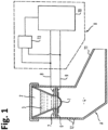
- FIG. 1 shows an embodiment of an inhalation therapy apparatus having an aerosol generator, in which in a nebuliser unit A, a liquid 3 stored in a liquid reservoir 2 is nebulised by means of a membrane 1 into a nebulisation chamber 4. Nebulisation (i.e. generation of an aerosol) occurs when the membrane 1 is caused to oscillate.
- the membrane 1 may be attached to an oscillation generation device, e.g. a support unit 6 which supports the membrane 1 and to which an electromechanical transducer unit 7, for example a piezoelectric element, may be attached.
- an oscillation generation device e.g. a support unit 6 which supports the membrane 1 and to which an electromechanical transducer unit 7, for example a piezoelectric element, may be attached.
- the membrane 1, the support unit 6 and the electromechanical transducer unit 7 may be considered as forming the aerosol generator and may be configured in a rotationally symmetrical manner in the embodiment described herein and together form an oscillatable structure.
- An activation signal of a control unit 10 can be supplied to the electromechanical transducer unit 7 via connecting lines or elements 8 and 9, where the control unit 10 may be accommodated in a separate controller B in the embodiment described herein.
- the oscillatable structure 1, 6, 7 is caused to oscillate and the liquid 3 is nebulised through the membrane 1 and is present on the other side of the membrane as an aerosol.
- a patient can inhale the aerosol provided in the nebulisation chamber 4 at the mouthpiece 11 of the nebuliser.
- one or more air holes 12 may be provided in the housing of the nebuliser, through which ambient air can enter into the chamber 4 during inhalation and out of which the air inhaled by the patient can exit from the chamber 4 during exhalation.
- pressure fluctuations occur in the chamber 4 during inhalation and exhalation.
- the pressure in the nebuliser chamber 4 sinks below the ambient pressure and during exhalation it rises above the ambient pressure.
- pressure equalisation occurs due to the air holes 12, it has been found that pressure fluctuations are generally sufficient to act upon the membrane 1 in a way that a usable respiration-dependent output signal is emitted by (e.g. can be extracted from the output of) the electromechanical transducer unit 7.
- the extent of the pressure fluctuations and thus the intensity of the effect of respiration of the patient upon the membrane 1 can be influenced by the design of the air holes 12 and preferably also by correspondingly designed valve elements at the air holes 12.
- This valve element may be designed at least as one one-way valve for the airflow in the nebulizer chamber 4.
- the nebulizer chamber 4 may further have an air outlet at the mouthpiece 11 of the nebuliser.
- the air outlet can be influenced by the design of the air outlet and preferably also by correspondingly designed second valve elements at the air outlet.
- This second valve element may be designed as a one-way valve for the airflow out of the nebulizer chamber 4.
- the nebulizer chamber may contain a one-way valve for the airflow in the nebulizer chamber and a one-way valve for the airflow out of the nebulizer chamber. Therefor the generated aerosol in the nebulizer chamber may accumulate during the exhalation of the patient and a quasi-aerosol-bolus be available during the inhalation of the patient.
- the breathing-induced pressure fluctuations also lead to a temperature effect at the electromechanical transducer unit 7.
- electrical operating the oscillation generating device such as the electromechanical transducer unit (e.g. a piezoelectric element)
- the electromechanical transducer unit e.g. a piezoelectric element
- the influence of generated Joule heat on the amplitude of the output signal is known in the context of detecting the presence of a liquid on the membrane, see EP 1 558 315 A1 , for example, the present inventors have realized that the breathing-induced pressure fluctuations also have a temperature effect on the operation of the electromechanical transducer unit which influences the output signal.
- pressure fluctuations at the oscillation generating device due to a patient or user breathing in and out a nebulizing chamber further leads to variations in a cooling off effect of air flowing by the electromechanical transducer and thus variations in the amount of Joule heat that can be momentarily transferred to the air flow.
- breathing-induced pressure changes at the oscillation generating device also lead to temperature variations of the oscillation generating device which have an additional effect on the output signal, in particular additional drift components, and thus prevent a stable output signal.
- a normal breathing pattern of a user or patient would be considered as a periodic function in the form of, for example: A 0 sin ⁇ t + ⁇ 1 having an breathing amplitude A 0 , breathing frequency ⁇ (e.g. having a frequency in the order of 0.1 - 1 Hz), time t and arbitrary phase ⁇ 1 , then breathing-induced pressure changes at the electromechanical transducer unit, as explained above, may lead to a corresponding periodic output signal: B 0 sin ⁇ t + ⁇ 2 having an amplitude B 0 (e.g.
- This example is used for illustration purposes, and the skilled person understands that actual breathing pattern of a user or patient may be more complex.
- the present inventors have recognized that the amplitude B 0 of the periodic output signal is not stable but has additional drift components which prevent an accurate evaluation of the output signal to detect the breathing pattern of the user or patient. As explained, these additional drift components are due to the additional temperature effect that the air flow fluctuations have on the electromechanical transducer unit. This additional temperature effect occurs on a time scale that is larger than an inhalation or exhalation and thus leads to the observed additional drift components in the output signal.
- an output signal caused by the respiration of the patient is available at the two connecting lines/elements 8 and 9 which can also be used to supply the activation signal to the oscillatable structure 1, 6, 7. Since excitation of the membrane 1 is caused by an electric signal whose frequency is much higher than the respiration frequency of a person, an output signal, which results from the pressure fluctuations in the nebulisation chamber 4 caused by the respiration of the patient, can be picked-up at the connection lines/elements 8, 9 of the oscillatable structure 1, 6, 7. The present inventors have further realized that this output signal should be suitably clamped in a processing unit 13.
- This clamping of the output signal (clamped respiration signal) in the processing unit 13 provides an improved holding or stabilization of the output signal at an amplitude value (B 0 ) around which the output signal has inhalation-induced variations, i.e. suppresses additional drift components of the amplitude.
- This clamped respiration signal may subsequently be supplied to the control unit 10 and may be taken into account therein when activating the inhalation therapy apparatus.
- the processing unit 13, via which the output signal at the at least one connecting lines/elements 8, 9 of the oscillation generating device 6, 7 is supplied to the control unit 10, provides a clamped respiration signal which follows the respiration process of the user or patient without additional drift terms.
- a suitable processing unit 13 is provided, which may be configured as a separate unit from the control unit 10. Alternatively, the processing unit 13 may also be integrated into the control unit 10.
- the processing unit 13 processes the output signal, which is influenced by the respiration of the patient, at the connections of the oscillatable structure 1, 6, 7, i.e. the aerosol generator, into a control signal (clamped respiration signal) which follows the respiration cycle of the patient.
- This processing may be implemented in different ways.
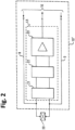
- Fig. 2 shows a preferred embodiment according to which the processing unit 13 comprises a plurality of sub-units described below.
- the oscillatable structure consisting of the membrane 1 and the oscillation generating device (e.g. the support element 6 and the piezo element 7) has been replaced in FIG. 2 by a schematic representation of an electromechanical piezo transducer 20.
- the respiration-influenced output signal of the piezo transducer 20, picked-up at the connecting lines/element is supplied in the processing unit 13 to a low-pass unit 21 which initially filters out the high frequency components of the picked-up signal, e.g. frequency components above 10 kHz, and thus, in particular, the components of the picked-up signal caused by the activation signal.
- the output signal of the low-pass filter 21 is supplied to a subsequent high-pass filter 22.
- the high-pass filter 22 may filter-out frequency components below 0.1 Hz, preferably below 0.05 Hz, more preferably below 0.01 Hz which have been found by the inventors to be related to the temperature effect at the electromechanical piezo transducer which follows the breathing-induced pressure fluctuations.
- a band-pass filter is implemented for also suppressing the temperature-induced fluctuations.
- the output signal of the high-pass filter 22 thus becomes free of additional drift components described above and is therefore clamped or hold/stabilized at an amplitude value that results from the breathing-induced pressure fluctuations.
- This output signal may then be supplied to an amplifier unit 23 which converts the supplied signal into a suitable clamped output signal (clamped respiration signal) for the control unit 10.
- the clamped respiration signal processed by the processing unit 13 may be supplied to the control unit 10, from which the activation signal for the piezo transducer 20 is supplied via the connecting lines 8 and 9.
- the dashed line in FIG. 2 indicates that the control unit 10 and the processing unit 13 can be arranged in a common housing or even in a single circuit arrangement/circuit.
- processing unit 13 may alternatively provide an order in which the high-pass filter 22 is followed by the low-pass filter 21 followed by the amplifier unit 23.
- the processing unit 23 may alternatively use analogue-to-digital conversion using a high-resolution analogue-to-digital converter (ADC) having a resolution of at least 20 Bit, and applying a signal evaluation by a digital evaluation unit or a digital signal processor (DSP) having a corresponding (high) sampling rate.
- ADC analogue-to-digital converter
- DSP digital signal processor
- the digital evaluation unit or the DSP may then be coupled to the control unit to appropriately control the operation of the inhalation therapy apparatus.
- the processing unit 13 may alternatively provide a band-pass filter 21' and the amplifier unit 23, wherein the band-pass filter unit 21a provides a band-pass between 0.1 Hz and at least 10 Hz, preferably 0.02 to 40 Hz to filter out both the high frequency components of the picked-up signal as well as the low frequency components due to the temperature fluctuations at the electromechanical piezo transducer.
- the band-pass filter unit 21a provides a band-pass between 0.1 Hz and at least 10 Hz, preferably 0.02 to 40 Hz to filter out both the high frequency components of the picked-up signal as well as the low frequency components due to the temperature fluctuations at the electromechanical piezo transducer.
- the present inventors have further realized that lowering the cut-off frequency of the low-pass filter unit or the upper cut-off frequency of the band-pass filter to values below 10 Hz, for example 2 Hz, would lead to a situation in which the output signal (clamped respiration signal) of the processing unit 13 could not follow a switch-on or switch-off of the aerosol generator fast enough. That is, the band-pass window preferably has a sufficient size to appropriately follow the transient switch-on or switch-off behaviour.
- the clamped respiration signal is tracked over a time period including one or more switch-on and switch-off operations to detect the presence of a fluid or liquid at the membrane.
- This appropriate and timely tracking of the output signal following a switch-on or switch-off is of particular advantage in cases which the operation of the aerosol generator is interrupted regularly (e.g. every 20 seconds) for detecting the presence of a fluid/liquid at the membrane, or during a power adjustment of the aerosol generator. This allows a suitable fast tracking of the clamped respiration signal over significant time periods.
- Fig. 3 shows another preferred embodiment according to which the processing unit 13 comprises a clamped low-pass filter unit 21b and an amplifier unit 23.
- the clamped low-pass filter unit 21b may be a low-pass filter unit having an additional clamped circuit.
- the clamped circuit e.g. a diode-based clamp (having a diode, a resistor, and a capacitor) allows to hold or clamp the output value of the low-pass filter unit at specific amplitude value.
- the specific amplitude value may be a value that is shifted from the DC component of the output signal caused by the respiration of a patient at the at least one connecting elements/lines 8, 9 of the oscillation generating device 6, 7, e.g.
- the resistor and capacitor of a diode-based clamp circuit determines a time constant and therefore a range of frequencies over which the clamped circuit becomes effective, the resistor and capacitor of the diode-based clamp circuit are suitably selected according to the appropriate band pass described above.
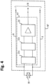
- Fig. 4 shows another preferred embodiment according to which the processing unit 13 comprises a clamped low-pass filter unit 21c, a clamped high-pass filter unit 22c and an amplifier unit 23.
- an additional clamped circuit may be provided for both the low-pass filter and the high-pass filter, or separate clamped circuits may be provided for each of the low-pass filter and the high-pass filter.
- Providing separate clamped circuits may have the advantage that respective resistor and capacitor dimensions of diode-based clamp circuits may be individually selected to more appropriately and selectively address lower and upper frequency values of the appropriate band pass described above.
- This clamped output signal of the processing unit 13 may subsequently be used by the control unit 10 such that the activation of the oscillatable structure 1, 6, 7 and thus nebulisation of the liquid 3 through the membrane 1 only occurs in the desired sections of the respiration cycle, for example only during inhalation.
- the respiration signal of the oscillatable structure 1, 6, 7, which is usable according to the invention allows for considerably more accurate information regarding the respiratory cycle of the patient, namely even if the activation signal is also supplied to the oscillatable structure 1, 6, 7 via the connecting lines 8 and 9.
- the two signals, namely the activation signal of the control unit 10 by means of which the oscillatable structure 1, 6, 7 is caused to oscillate, and the output signal of the oscillatable structure 1, 6, 7, caused by the respiration of the patient, superpose one another.
- the output signal at the connecting element 8, 9 of the oscillatable structure 1, 6, 7, which is caused by pressure fluctuations, is much smaller than the activation signal which is fed from the control unit 10 to the oscillatable structure 1, 6, 7 via the connecting lines 8 and 9, has additional drift components due to a temperature effect at the oscillatable structure and therefore requires appropriate processing in order to more reliably detect the breathing cycle.
- optical or acoustical indications can be given more reliably to the patient to optimise respiratory flow, or aerosol generation can be automatically shut-off more reliably if too high or too low respiratory flows are detected which are unfavourable for a safe intrapulmonary aerosol deposition.
- control unit 10 is preferably configured such that no low-frequency signal components due to temperature fluctuations at the oscillatable structure 1, 6, 7 are used for nebulising the liquid 3. It is also achieved by means of this design that the output signal caused by the respiration of the patient can be more reliably separated from the activation signal with comparatively little more effort and thus in an inexpensive manner.
- Fig. 5 shows a schematic illustration of a comparison between a non-clamped respiration signal (upper panel) and a clamed respiration signal (lower panel).
- the X axis shows a time interval between 0.0 and 4.5 seconds while the Y-axis shows a voltage of the output signal, as well as a (dashed line) input signal having a disruption between 0.25 and 0.5 seconds and a (continuous line) output signal that is not clamped.
- the X axis shows a time interval between 0.0 and 3.5 seconds while the Y-axis shows a voltage of the output signal, as well as a (dashed line) input signal having the disruption between 0.25 and 0.5 seconds and a (continuous line) output signal that is clamped according to the embodiments of the present inventions.
- the clamped output signal is stable 1 second after the disruption and is a clamped output signal without outliers (drift terms) and cutting offs. That is, the breathing pattern can be detected accurately and fast.
- Fig. 6 shows another schematic illustration of a comparison between a non-clamped respiration signal and a clamped respiration signal.
- the X-axis illustrates a time axis in units of 0.1 sec (i.e. time step 541 refers to 54.1 seconds) and the Y-axis illustrates a voltage signal, in this illustrated example a digital value of the voltage ( ⁇ V) wherein the AD converter has a 12 bit resolution (with 4096 data values).
- the clamped output signal is free of the power peaks or interruptions (e.g. due to electrostatic discharges), e.g. at time steps 241, 401 and 441.
- the breathing pattern can be detected more accurately, even at the time step 401 having a large peak in the non-clamped output signal.
- the clamped output signal also clearly indicates that breathing has stopped after time step 441.
- the control unit (10) may use the clamped output signal for a different subsequent processing, monitoring or actions, like for example a stand-by function, a pause-function, to start the activation signal, to stop the activation signal, or to show on a monitor or a display, like for example on the inhalation therapy apparatus, on a web-portal or a smart-phone in an app.
- monitoring or actions like for example a stand-by function, a pause-function
- start the activation signal to stop the activation signal
- a display like for example on the inhalation therapy apparatus, on a web-portal or a smart-phone in an app.
- EP 15810730.0 published and granted as EP 3237047 which is included entirely with the specification and the figures. (Equivalent to US 2017/0368282 and US 15/535,889 )
- the invention can be primarily used in such inhalation therapy apparatuses in which an electromechanical transducer unit is provided, which causes an oscillatable structure that effects generation of the aerosol to begin to oscillate.
- Inhalation therapy apparatuses in which the electromechanical transducer unit is configured in the form of a piezoelectric element are particularly suitable for the use of the invention.
Landscapes
- Health & Medical Sciences (AREA)
- Engineering & Computer Science (AREA)
- General Health & Medical Sciences (AREA)
- Biomedical Technology (AREA)
- Public Health (AREA)
- Veterinary Medicine (AREA)
- Life Sciences & Earth Sciences (AREA)
- Animal Behavior & Ethology (AREA)
- Hematology (AREA)
- Heart & Thoracic Surgery (AREA)
- Anesthesiology (AREA)
- Medical Informatics (AREA)
- Epidemiology (AREA)
- Primary Health Care (AREA)
- Bioinformatics & Cheminformatics (AREA)
- Pulmonology (AREA)
- General Business, Economics & Management (AREA)
- Business, Economics & Management (AREA)
- Nuclear Medicine, Radiotherapy & Molecular Imaging (AREA)
- Surgery (AREA)
- Urology & Nephrology (AREA)
- Mechanical Engineering (AREA)
- Percussion Or Vibration Massage (AREA)
Priority Applications (5)
| Application Number | Priority Date | Filing Date | Title |
|---|---|---|---|
| EP22153887.9A EP4218865B1 (fr) | 2022-01-28 | 2022-01-28 | Appareil de thérapie par inhalation |
| ES22153887T ES2994160T3 (en) | 2022-01-28 | 2022-01-28 | Inhalation therapy apparatus |
| PCT/EP2023/051757 WO2023144181A1 (fr) | 2022-01-28 | 2023-01-25 | Appareil de traitement par inhalation |
| US18/832,326 US20250152868A1 (en) | 2022-01-28 | 2023-01-25 | Inhalation therapy apparatus |
| EP23701742.1A EP4469115A1 (fr) | 2022-01-28 | 2023-01-25 | Appareil de traitement par inhalation |
Applications Claiming Priority (1)
| Application Number | Priority Date | Filing Date | Title |
|---|---|---|---|
| EP22153887.9A EP4218865B1 (fr) | 2022-01-28 | 2022-01-28 | Appareil de thérapie par inhalation |
Publications (2)
| Publication Number | Publication Date |
|---|---|
| EP4218865A1 true EP4218865A1 (fr) | 2023-08-02 |
| EP4218865B1 EP4218865B1 (fr) | 2024-10-23 |
Family
ID=80122453
Family Applications (2)
| Application Number | Title | Priority Date | Filing Date |
|---|---|---|---|
| EP22153887.9A Active EP4218865B1 (fr) | 2022-01-28 | 2022-01-28 | Appareil de thérapie par inhalation |
| EP23701742.1A Pending EP4469115A1 (fr) | 2022-01-28 | 2023-01-25 | Appareil de traitement par inhalation |
Family Applications After (1)
| Application Number | Title | Priority Date | Filing Date |
|---|---|---|---|
| EP23701742.1A Pending EP4469115A1 (fr) | 2022-01-28 | 2023-01-25 | Appareil de traitement par inhalation |
Country Status (4)
| Country | Link |
|---|---|
| US (1) | US20250152868A1 (fr) |
| EP (2) | EP4218865B1 (fr) |
| ES (1) | ES2994160T3 (fr) |
| WO (1) | WO2023144181A1 (fr) |
Cited By (1)
| Publication number | Priority date | Publication date | Assignee | Title |
|---|---|---|---|---|
| WO2024160951A1 (fr) | 2023-02-01 | 2024-08-08 | Pari Medical Holding Gmbh | Procédé d'évaluation médicale, nébuliseur d'aérosol et système d'évaluation médicale |
Citations (9)
| Publication number | Priority date | Publication date | Assignee | Title |
|---|---|---|---|---|
| US5415161A (en) * | 1993-09-15 | 1995-05-16 | Ryder; Steven L. | Intermittant demand aerosol control device |
| EP1227856A1 (fr) | 1999-11-05 | 2002-08-07 | PARI GmbH Spezialisten für effektive Inhalation | Nebuliseur d'inhalation |
| US20050034719A1 (en) * | 2001-10-18 | 2005-02-17 | Franz Feiner | Inhalation therapy apparatus |
| US20050056274A1 (en) * | 2001-10-18 | 2005-03-17 | Pari Gmbh Spezialisten Fur Effektive | Device for inhalation therapy |
| EP1558315A1 (fr) | 2002-10-30 | 2005-08-03 | PARI GmbH Spezialisten für effektive Inhalation | Appareil de therapie par inhalation |
| EP3237047A1 (fr) | 2014-12-23 | 2017-11-01 | PARI Pharma GmbH | Dispositif de distribution d'aérosol et procédés de fonctionnement du dispositif de distribution d'aérosol |
| US20190321570A1 (en) * | 2010-08-23 | 2019-10-24 | Darren Rubin | Systems and methods of aerosol delivery with airflow regulation |
| EP3666315A1 (fr) * | 2018-12-14 | 2020-06-17 | PARI Pharma GmbH | Dispositif d'administration d'aérosol et procédé de fonctionnement du dispositif d'administration d'aérosol |
| EP3711797A1 (fr) * | 2013-12-16 | 2020-09-23 | PARI Pharma GmbH | Dispositif d'administration d'aérosol et procédé de fonctionnement du dispositif d'administration d'aérosol |
-
2022
- 2022-01-28 ES ES22153887T patent/ES2994160T3/es active Active
- 2022-01-28 EP EP22153887.9A patent/EP4218865B1/fr active Active
-
2023
- 2023-01-25 WO PCT/EP2023/051757 patent/WO2023144181A1/fr not_active Ceased
- 2023-01-25 EP EP23701742.1A patent/EP4469115A1/fr active Pending
- 2023-01-25 US US18/832,326 patent/US20250152868A1/en active Pending
Patent Citations (11)
| Publication number | Priority date | Publication date | Assignee | Title |
|---|---|---|---|---|
| US5415161A (en) * | 1993-09-15 | 1995-05-16 | Ryder; Steven L. | Intermittant demand aerosol control device |
| EP1227856A1 (fr) | 1999-11-05 | 2002-08-07 | PARI GmbH Spezialisten für effektive Inhalation | Nebuliseur d'inhalation |
| US20050034719A1 (en) * | 2001-10-18 | 2005-02-17 | Franz Feiner | Inhalation therapy apparatus |
| US20050056274A1 (en) * | 2001-10-18 | 2005-03-17 | Pari Gmbh Spezialisten Fur Effektive | Device for inhalation therapy |
| EP1304131B1 (fr) | 2001-10-18 | 2005-06-29 | PARI GmbH Spezialisten für effektive Inhalation | Appareil de ventilation |
| EP1558315A1 (fr) | 2002-10-30 | 2005-08-03 | PARI GmbH Spezialisten für effektive Inhalation | Appareil de therapie par inhalation |
| US20190321570A1 (en) * | 2010-08-23 | 2019-10-24 | Darren Rubin | Systems and methods of aerosol delivery with airflow regulation |
| EP3711797A1 (fr) * | 2013-12-16 | 2020-09-23 | PARI Pharma GmbH | Dispositif d'administration d'aérosol et procédé de fonctionnement du dispositif d'administration d'aérosol |
| EP3237047A1 (fr) | 2014-12-23 | 2017-11-01 | PARI Pharma GmbH | Dispositif de distribution d'aérosol et procédés de fonctionnement du dispositif de distribution d'aérosol |
| US20170368282A1 (en) | 2014-12-23 | 2017-12-28 | Pari Pharma Gmbh | Aerosol delivery device and operating method for the aerosol delivery device |
| EP3666315A1 (fr) * | 2018-12-14 | 2020-06-17 | PARI Pharma GmbH | Dispositif d'administration d'aérosol et procédé de fonctionnement du dispositif d'administration d'aérosol |
Cited By (1)
| Publication number | Priority date | Publication date | Assignee | Title |
|---|---|---|---|---|
| WO2024160951A1 (fr) | 2023-02-01 | 2024-08-08 | Pari Medical Holding Gmbh | Procédé d'évaluation médicale, nébuliseur d'aérosol et système d'évaluation médicale |
Also Published As
| Publication number | Publication date |
|---|---|
| ES2994160T3 (en) | 2025-01-20 |
| EP4218865B1 (fr) | 2024-10-23 |
| WO2023144181A1 (fr) | 2023-08-03 |
| US20250152868A1 (en) | 2025-05-15 |
| EP4469115A1 (fr) | 2024-12-04 |
Similar Documents
| Publication | Publication Date | Title |
|---|---|---|
| US7059320B2 (en) | Inhalation therapy apparatus | |
| US9713681B2 (en) | Method and nebulization module providing constant electric power by automatic compensation | |
| US12280397B2 (en) | System and methods for controlling patient leakage current in a surgical system | |
| US9296005B2 (en) | Nozzle replaceable atomizer with automatic abnormality detecting function | |
| US9521493B2 (en) | Transducer impedance measurement for hearing aid | |
| US3828773A (en) | Nebulizing apparatus and system | |
| US8386042B2 (en) | Omnidirectional accelerometer device and medical device incorporating same | |
| EP4218865A1 (fr) | Appareil de thérapie par inhalation | |
| US10201673B2 (en) | Nebulizer, a control unit for controlling the same and a method of operating a nebulizer | |
| RU2570613C2 (ru) | Небулайзер, блок управления для управления им и способ управления небулайзером | |
| KR20190133172A (ko) | 산화 질소 발생 시스템 및 방법 | |
| RU2017113542A (ru) | Системы и способы синтеза оксида азота | |
| EP3672734B1 (fr) | Protection d'une plaque munie d'orifice durant la génération d'un aérosol | |
| EP4353107A1 (fr) | Appareil d'atomisation électronique et procédé de commande | |
| CN104424731B (zh) | 无声地监控警报发声器的装置和方法 | |
| JP4314061B2 (ja) | 超音波振動子の制御装置およびこれを用いた超音波霧化装置 | |
| WO2010067239A2 (fr) | Système et procédé de contrôle de nébulisation d'un médicament | |
| WO2016006495A1 (fr) | Dispositif d'aspiration | |
| EP4262943B1 (fr) | Détection de la présence de liquide dans un nébuliseur à membrane vibrante | |
| CN102787370B (zh) | 一种使用压电陶瓷检测缫丝机茧丝断丝的装置 | |
| EP4531716A1 (fr) | Ensemble chirurgical et système | |
| CN114630695A (zh) | 心脏辅助系统的报警方式 | |
| TW201543405A (zh) | 智慧型霧化器之控管方法 | |
| JP2009198222A (ja) | 検出装置 |
Legal Events
| Date | Code | Title | Description |
|---|---|---|---|
| PUAI | Public reference made under article 153(3) epc to a published international application that has entered the european phase |
Free format text: ORIGINAL CODE: 0009012 |
|
| STAA | Information on the status of an ep patent application or granted ep patent |
Free format text: STATUS: THE APPLICATION HAS BEEN PUBLISHED |
|
| AK | Designated contracting states |
Kind code of ref document: A1 Designated state(s): AL AT BE BG CH CY CZ DE DK EE ES FI FR GB GR HR HU IE IS IT LI LT LU LV MC MK MT NL NO PL PT RO RS SE SI SK SM TR |
|
| STAA | Information on the status of an ep patent application or granted ep patent |
Free format text: STATUS: REQUEST FOR EXAMINATION WAS MADE |
|
| 17P | Request for examination filed |
Effective date: 20240201 |
|
| RBV | Designated contracting states (corrected) |
Designated state(s): AL AT BE BG CH CY CZ DE DK EE ES FI FR GB GR HR HU IE IS IT LI LT LU LV MC MK MT NL NO PL PT RO RS SE SI SK SM TR |
|
| GRAP | Despatch of communication of intention to grant a patent |
Free format text: ORIGINAL CODE: EPIDOSNIGR1 |
|
| STAA | Information on the status of an ep patent application or granted ep patent |
Free format text: STATUS: GRANT OF PATENT IS INTENDED |
|
| INTG | Intention to grant announced |
Effective date: 20240607 |
|
| GRAS | Grant fee paid |
Free format text: ORIGINAL CODE: EPIDOSNIGR3 |
|
| GRAA | (expected) grant |
Free format text: ORIGINAL CODE: 0009210 |
|
| STAA | Information on the status of an ep patent application or granted ep patent |
Free format text: STATUS: THE PATENT HAS BEEN GRANTED |
|
| AK | Designated contracting states |
Kind code of ref document: B1 Designated state(s): AL AT BE BG CH CY CZ DE DK EE ES FI FR GB GR HR HU IE IS IT LI LT LU LV MC MK MT NL NO PL PT RO RS SE SI SK SM TR |
|
| REG | Reference to a national code |
Ref country code: GB Ref legal event code: FG4D |
|
| REG | Reference to a national code |
Ref country code: CH Ref legal event code: EP |
|
| REG | Reference to a national code |
Ref country code: DE Ref legal event code: R096 Ref document number: 602022006934 Country of ref document: DE |
|
| REG | Reference to a national code |
Ref country code: IE Ref legal event code: FG4D |
|
| P01 | Opt-out of the competence of the unified patent court (upc) registered |
Free format text: CASE NUMBER: APP_62308/2024 Effective date: 20241121 |
|
| REG | Reference to a national code |
Ref country code: ES Ref legal event code: FG2A Ref document number: 2994160 Country of ref document: ES Kind code of ref document: T3 Effective date: 20250120 |
|
| REG | Reference to a national code |
Ref country code: LT Ref legal event code: MG9D |
|
| REG | Reference to a national code |
Ref country code: NL Ref legal event code: MP Effective date: 20241023 |
|
| REG | Reference to a national code |
Ref country code: AT Ref legal event code: MK05 Ref document number: 1734321 Country of ref document: AT Kind code of ref document: T Effective date: 20241023 |
|
| PG25 | Lapsed in a contracting state [announced via postgrant information from national office to epo] |
Ref country code: NL Free format text: LAPSE BECAUSE OF FAILURE TO SUBMIT A TRANSLATION OF THE DESCRIPTION OR TO PAY THE FEE WITHIN THE PRESCRIBED TIME-LIMIT Effective date: 20241023 |
|
| PG25 | Lapsed in a contracting state [announced via postgrant information from national office to epo] |
Ref country code: NL Free format text: LAPSE BECAUSE OF FAILURE TO SUBMIT A TRANSLATION OF THE DESCRIPTION OR TO PAY THE FEE WITHIN THE PRESCRIBED TIME-LIMIT Effective date: 20241023 |
|
| PG25 | Lapsed in a contracting state [announced via postgrant information from national office to epo] |
Ref country code: HR Free format text: LAPSE BECAUSE OF FAILURE TO SUBMIT A TRANSLATION OF THE DESCRIPTION OR TO PAY THE FEE WITHIN THE PRESCRIBED TIME-LIMIT Effective date: 20241023 Ref country code: PT Free format text: LAPSE BECAUSE OF FAILURE TO SUBMIT A TRANSLATION OF THE DESCRIPTION OR TO PAY THE FEE WITHIN THE PRESCRIBED TIME-LIMIT Effective date: 20250224 Ref country code: IS Free format text: LAPSE BECAUSE OF FAILURE TO SUBMIT A TRANSLATION OF THE DESCRIPTION OR TO PAY THE FEE WITHIN THE PRESCRIBED TIME-LIMIT Effective date: 20250223 |
|
| PG25 | Lapsed in a contracting state [announced via postgrant information from national office to epo] |
Ref country code: FI Free format text: LAPSE BECAUSE OF FAILURE TO SUBMIT A TRANSLATION OF THE DESCRIPTION OR TO PAY THE FEE WITHIN THE PRESCRIBED TIME-LIMIT Effective date: 20241023 |
|
| PG25 | Lapsed in a contracting state [announced via postgrant information from national office to epo] |
Ref country code: BG Free format text: LAPSE BECAUSE OF FAILURE TO SUBMIT A TRANSLATION OF THE DESCRIPTION OR TO PAY THE FEE WITHIN THE PRESCRIBED TIME-LIMIT Effective date: 20241023 |
|
| PG25 | Lapsed in a contracting state [announced via postgrant information from national office to epo] |
Ref country code: NO Free format text: LAPSE BECAUSE OF FAILURE TO SUBMIT A TRANSLATION OF THE DESCRIPTION OR TO PAY THE FEE WITHIN THE PRESCRIBED TIME-LIMIT Effective date: 20250123 |
|
| PG25 | Lapsed in a contracting state [announced via postgrant information from national office to epo] |
Ref country code: LV Free format text: LAPSE BECAUSE OF FAILURE TO SUBMIT A TRANSLATION OF THE DESCRIPTION OR TO PAY THE FEE WITHIN THE PRESCRIBED TIME-LIMIT Effective date: 20241023 Ref country code: GR Free format text: LAPSE BECAUSE OF FAILURE TO SUBMIT A TRANSLATION OF THE DESCRIPTION OR TO PAY THE FEE WITHIN THE PRESCRIBED TIME-LIMIT Effective date: 20250124 Ref country code: AT Free format text: LAPSE BECAUSE OF FAILURE TO SUBMIT A TRANSLATION OF THE DESCRIPTION OR TO PAY THE FEE WITHIN THE PRESCRIBED TIME-LIMIT Effective date: 20241023 |
|
| PG25 | Lapsed in a contracting state [announced via postgrant information from national office to epo] |
Ref country code: PL Free format text: LAPSE BECAUSE OF FAILURE TO SUBMIT A TRANSLATION OF THE DESCRIPTION OR TO PAY THE FEE WITHIN THE PRESCRIBED TIME-LIMIT Effective date: 20241023 |
|
| PG25 | Lapsed in a contracting state [announced via postgrant information from national office to epo] |
Ref country code: RS Free format text: LAPSE BECAUSE OF FAILURE TO SUBMIT A TRANSLATION OF THE DESCRIPTION OR TO PAY THE FEE WITHIN THE PRESCRIBED TIME-LIMIT Effective date: 20250123 |
|
| PG25 | Lapsed in a contracting state [announced via postgrant information from national office to epo] |
Ref country code: SM Free format text: LAPSE BECAUSE OF FAILURE TO SUBMIT A TRANSLATION OF THE DESCRIPTION OR TO PAY THE FEE WITHIN THE PRESCRIBED TIME-LIMIT Effective date: 20241023 |
|
| PG25 | Lapsed in a contracting state [announced via postgrant information from national office to epo] |
Ref country code: DK Free format text: LAPSE BECAUSE OF FAILURE TO SUBMIT A TRANSLATION OF THE DESCRIPTION OR TO PAY THE FEE WITHIN THE PRESCRIBED TIME-LIMIT Effective date: 20241023 |
|
| PG25 | Lapsed in a contracting state [announced via postgrant information from national office to epo] |
Ref country code: EE Free format text: LAPSE BECAUSE OF FAILURE TO SUBMIT A TRANSLATION OF THE DESCRIPTION OR TO PAY THE FEE WITHIN THE PRESCRIBED TIME-LIMIT Effective date: 20241023 |
|
| PG25 | Lapsed in a contracting state [announced via postgrant information from national office to epo] |
Ref country code: RO Free format text: LAPSE BECAUSE OF FAILURE TO SUBMIT A TRANSLATION OF THE DESCRIPTION OR TO PAY THE FEE WITHIN THE PRESCRIBED TIME-LIMIT Effective date: 20241023 |
|
| REG | Reference to a national code |
Ref country code: DE Ref legal event code: R097 Ref document number: 602022006934 Country of ref document: DE |
|
| PG25 | Lapsed in a contracting state [announced via postgrant information from national office to epo] |
Ref country code: SK Free format text: LAPSE BECAUSE OF FAILURE TO SUBMIT A TRANSLATION OF THE DESCRIPTION OR TO PAY THE FEE WITHIN THE PRESCRIBED TIME-LIMIT Effective date: 20241023 |
|
| PG25 | Lapsed in a contracting state [announced via postgrant information from national office to epo] |
Ref country code: CZ Free format text: LAPSE BECAUSE OF FAILURE TO SUBMIT A TRANSLATION OF THE DESCRIPTION OR TO PAY THE FEE WITHIN THE PRESCRIBED TIME-LIMIT Effective date: 20241023 |
|
| PLBE | No opposition filed within time limit |
Free format text: ORIGINAL CODE: 0009261 |
|
| REG | Reference to a national code |
Ref country code: CH Ref legal event code: PL |
|
| STAA | Information on the status of an ep patent application or granted ep patent |
Free format text: STATUS: NO OPPOSITION FILED WITHIN TIME LIMIT |
|
| PG25 | Lapsed in a contracting state [announced via postgrant information from national office to epo] |
Ref country code: SE Free format text: LAPSE BECAUSE OF FAILURE TO SUBMIT A TRANSLATION OF THE DESCRIPTION OR TO PAY THE FEE WITHIN THE PRESCRIBED TIME-LIMIT Effective date: 20241023 |
|
| PG25 | Lapsed in a contracting state [announced via postgrant information from national office to epo] |
Ref country code: LU Free format text: LAPSE BECAUSE OF NON-PAYMENT OF DUE FEES Effective date: 20250128 Ref country code: MC Free format text: LAPSE BECAUSE OF FAILURE TO SUBMIT A TRANSLATION OF THE DESCRIPTION OR TO PAY THE FEE WITHIN THE PRESCRIBED TIME-LIMIT Effective date: 20241023 |
|
| 26N | No opposition filed |
Effective date: 20250724 |
|
| PG25 | Lapsed in a contracting state [announced via postgrant information from national office to epo] |
Ref country code: BE Free format text: LAPSE BECAUSE OF NON-PAYMENT OF DUE FEES Effective date: 20250131 |
|
| PG25 | Lapsed in a contracting state [announced via postgrant information from national office to epo] |
Ref country code: CH Free format text: LAPSE BECAUSE OF NON-PAYMENT OF DUE FEES Effective date: 20250131 |
|
| REG | Reference to a national code |
Ref country code: BE Ref legal event code: MM Effective date: 20250131 |
|
| PG25 | Lapsed in a contracting state [announced via postgrant information from national office to epo] |
Ref country code: IE Free format text: LAPSE BECAUSE OF NON-PAYMENT OF DUE FEES Effective date: 20250128 |
|
| PGFP | Annual fee paid to national office [announced via postgrant information from national office to epo] |
Ref country code: GB Payment date: 20260122 Year of fee payment: 5 |
|
| PGFP | Annual fee paid to national office [announced via postgrant information from national office to epo] |
Ref country code: ES Payment date: 20260217 Year of fee payment: 5 |
|
| PGFP | Annual fee paid to national office [announced via postgrant information from national office to epo] |
Ref country code: DE Payment date: 20260120 Year of fee payment: 5 |
|
| PGFP | Annual fee paid to national office [announced via postgrant information from national office to epo] |
Ref country code: IT Payment date: 20260130 Year of fee payment: 5 |
|
| PGFP | Annual fee paid to national office [announced via postgrant information from national office to epo] |
Ref country code: FR Payment date: 20260128 Year of fee payment: 5 |