EP4219073A1 - Dispositif outil rotatif à entraînement rotatif - Google Patents
Dispositif outil rotatif à entraînement rotatif Download PDFInfo
- Publication number
- EP4219073A1 EP4219073A1 EP22153482.9A EP22153482A EP4219073A1 EP 4219073 A1 EP4219073 A1 EP 4219073A1 EP 22153482 A EP22153482 A EP 22153482A EP 4219073 A1 EP4219073 A1 EP 4219073A1
- Authority
- EP
- European Patent Office
- Prior art keywords
- tool
- clamping element
- groove
- drive
- rotary
- Prior art date
- Legal status (The legal status is an assumption and is not a legal conclusion. Google has not performed a legal analysis and makes no representation as to the accuracy of the status listed.)
- Pending
Links
Images


Classifications
-
- B—PERFORMING OPERATIONS; TRANSPORTING
- B24—GRINDING; POLISHING
- B24B—MACHINES, DEVICES, OR PROCESSES FOR GRINDING OR POLISHING; DRESSING OR CONDITIONING OF ABRADING SURFACES; FEEDING OF GRINDING, POLISHING, OR LAPPING AGENTS
- B24B41/00—Component parts such as frames, beds, carriages, headstocks
- B24B41/04—Headstocks; Working-spindles; Features relating thereto
-
- B—PERFORMING OPERATIONS; TRANSPORTING
- B24—GRINDING; POLISHING
- B24B—MACHINES, DEVICES, OR PROCESSES FOR GRINDING OR POLISHING; DRESSING OR CONDITIONING OF ABRADING SURFACES; FEEDING OF GRINDING, POLISHING, OR LAPPING AGENTS
- B24B45/00—Means for securing grinding wheels on rotary arbors
- B24B45/006—Quick mount and release means for disc-like wheels, e.g. on power tools
-
- B—PERFORMING OPERATIONS; TRANSPORTING
- B24—GRINDING; POLISHING
- B24B—MACHINES, DEVICES, OR PROCESSES FOR GRINDING OR POLISHING; DRESSING OR CONDITIONING OF ABRADING SURFACES; FEEDING OF GRINDING, POLISHING, OR LAPPING AGENTS
- B24B23/00—Portable grinding machines, e.g. hand-guided; Accessories therefor
- B24B23/02—Portable grinding machines, e.g. hand-guided; Accessories therefor with rotating grinding tools; Accessories therefor
- B24B23/022—Spindle-locking devices, e.g. for mounting or removing the tool
-
- B—PERFORMING OPERATIONS; TRANSPORTING
- B24—GRINDING; POLISHING
- B24B—MACHINES, DEVICES, OR PROCESSES FOR GRINDING OR POLISHING; DRESSING OR CONDITIONING OF ABRADING SURFACES; FEEDING OF GRINDING, POLISHING, OR LAPPING AGENTS
- B24B29/00—Machines or devices for polishing surfaces on work by means of tools made of soft or flexible material with or without the application of solid or liquid polishing agents
- B24B29/005—Machines or devices for polishing surfaces on work by means of tools made of soft or flexible material with or without the application of solid or liquid polishing agents using brushes
-
- F—MECHANICAL ENGINEERING; LIGHTING; HEATING; WEAPONS; BLASTING
- F16—ENGINEERING ELEMENTS AND UNITS; GENERAL MEASURES FOR PRODUCING AND MAINTAINING EFFECTIVE FUNCTIONING OF MACHINES OR INSTALLATIONS; THERMAL INSULATION IN GENERAL
- F16B—DEVICES FOR FASTENING OR SECURING CONSTRUCTIONAL ELEMENTS OR MACHINE PARTS TOGETHER, e.g. NAILS, BOLTS, CIRCLIPS, CLAMPS, CLIPS OR WEDGES; JOINTS OR JOINTING
- F16B21/00—Means for preventing relative axial movement of a pin, spigot, shaft or the like and a member surrounding it; Stud-and-socket releasable fastenings
- F16B21/02—Releasable fastening devices locking by rotation
- F16B21/04—Releasable fastening devices locking by rotation with bayonet catch
-
- F—MECHANICAL ENGINEERING; LIGHTING; HEATING; WEAPONS; BLASTING
- F16—ENGINEERING ELEMENTS AND UNITS; GENERAL MEASURES FOR PRODUCING AND MAINTAINING EFFECTIVE FUNCTIONING OF MACHINES OR INSTALLATIONS; THERMAL INSULATION IN GENERAL
- F16D—COUPLINGS FOR TRANSMITTING ROTATION; CLUTCHES; BRAKES
- F16D1/00—Couplings for rigidly connecting two coaxial shafts or other movable machine elements
- F16D1/10—Quick-acting couplings in which the parts are connected by simply bringing them together axially
- F16D1/108—Quick-acting couplings in which the parts are connected by simply bringing them together axially having retaining means rotating with the coupling and acting by interengaging parts, i.e. positive coupling
- F16D1/112—Quick-acting couplings in which the parts are connected by simply bringing them together axially having retaining means rotating with the coupling and acting by interengaging parts, i.e. positive coupling the interengaging parts comprising torque-transmitting surfaces, e.g. bayonet joints
-
- Y—GENERAL TAGGING OF NEW TECHNOLOGICAL DEVELOPMENTS; GENERAL TAGGING OF CROSS-SECTIONAL TECHNOLOGIES SPANNING OVER SEVERAL SECTIONS OF THE IPC; TECHNICAL SUBJECTS COVERED BY FORMER USPC CROSS-REFERENCE ART COLLECTIONS [XRACs] AND DIGESTS
- Y10—TECHNICAL SUBJECTS COVERED BY FORMER USPC
- Y10T—TECHNICAL SUBJECTS COVERED BY FORMER US CLASSIFICATION
- Y10T403/00—Joints and connections
- Y10T403/70—Interfitted members
- Y10T403/7005—Lugged member, rotary engagement
- Y10T403/7007—Bayonet joint
Definitions
- the invention relates to a rotationally drivable rotary tool device, in particular a rotary brush tool, with a tool holder having at least one drive-side clamping element and a tool-side clamping element, the two clamping elements being detachably connected to one another and receiving and holding a rotary tool.
- the clamping element on the drive side can be set in rotation, for example via a mandrel or the like with the aid of a rotary drive unit.
- the tool-side clamping element typically serves to accommodate and hold the turning tool.
- a rotationally drivable rotary tool device of the structure described above as in the EP 2 371 487 B1 is described, two specially designed tensioning elements are provided and releasably coupled with the aid of a closure element against the force of at least one spring.
- the two clamping elements and the associated tool holder are used to hold the turning tool.
- the rotary tool can be a rotary brush with a flexible brush belt, such as is also relevant at this point DE 42 05 265 C1 the applicant is described.
- a rotary tool according to EP 1 859 903 B1 be included.
- a comparable rotationally drivable rotary tool device is in the DE 100 30 586 A1 described.
- a tool with a circular disc-shaped tool body is used here.
- the tool body has a central opening for attachment to a machine tool or generally to a rotary drive unit.
- a carrying device is provided in the opening, which engages over the edge of the opening at least on one side of the tool body.
- a fastening device is provided on the other side of the tool body, which can be clamped onto the machine tool and to which the carrying device can be releasably fastened when the fastening device is clamped.
- the tool body as a whole is secured axially and held in a rotationally fixed manner.
- the known carrying device is obviously only suitable in connection with circular disk-shaped tool bodies designed as cutting or grinding disks.
- Rotary brush tools are also known from practice and from the literature in a variety of configurations. This is how the DE 43 26 793 C1 with a rotationally drivable brush unit, in which the brush holder has two end disks spaced apart by a split spacer bush and the end disks have axial webs arranged at a predetermined distance from the bush jacket and distributed over the disk circumference.
- the ring brush has a flexible brush belt with bristles protruding outwards and with bristle-free belt zones for the axial webs that overlap the brush belt.
- the brush belt carrier and the brush belt can form a unit. This is intended to achieve versatile use and an effective effect and at the same time longevity.
- the ring brush or its brush belt does not “fit” exactly and in relation to the tool holder performs more or less uncontrolled movements. As a result of this, increased wear and even destruction of the ring brush during operation is often observed.
- the prior art which is also generic and closest, is based on WO 2017/220338 A1 so that the tool-side clamping element and the turning tool define a structural unit.
- the clamping element in question is designed as a retaining cage that at least partially radially and axially encloses the turning tool.
- the clamping element on the drive side is designed as a holder adapter which engages in the holding cage in a detachable manner.
- the holding adapter has locking pins on the circumference, which, when the holding cage is in the mounted state on the holding adapter, engage in associated receiving bores in the holding cage. This has basically proven itself and also allows the turning tool to be changed quickly and with little effort.
- the invention is based on the technical problem of further developing such a rotationally drivable rotary tool device in such a way that a quicker and functionally correct replacement of the tool-side clamping element is possible the turning tool in relation to the clamping element on the drive side is possible and easily achieved even when it is dirty.
- a rotary tool device of the generic type that can be driven in rotation is characterized within the scope of the invention in that the clamping element on the tool side and the clamping element on the drive side are coupled to one another via a bayonet connection.
- the detachable connection between the two clamping elements is realized and implemented according to the invention via a bayonet connection.
- a bayonet connection provides a mechanical connection between the clamping element on the drive side and the clamping element on the tool side that can be established and released quickly.
- the two elements are plugged into one another and connected to one another or separated again by turning them in opposite directions.
- the clamping element on the drive side is typically designed cylindrically, while the clamping element on the tool side is a corresponding cylinder sleeve or cylinder disk.
- the drive-side clamping element has at least one receiving groove and the tool-side clamping element has at least one pin engaging in the receiving groove.
- the clamping element on the drive side is equipped with the at least one pin in question, which in turn engages in the receiving groove in the clamping element on the tool side.
- the receiving groove as part of the bayonet connection is usually at least in two parts with an axial groove and a subsequent radial groove formed. In most cases, the design is then made in such a way that the radial groove merges into a locking groove at the end.
- the latching groove is advantageously designed as a blind groove running parallel to the axial groove.
- the receiving groove on the drive-side tensioning element is generally designed in three parts with the axial groove, the radial groove adjoining it and the latching groove provided at the end of the radial groove.
- a combined movement occurs when the drive-side clamping element and the tool-side clamping element are combined in such a way that the tool-side clamping element is first introduced with its pin into the axial groove. This usually happens against the force of at least one spring acting on the clamping element on the tool side. This results in a sliding or "push" movement.
- the spring acting on the clamping element on the tool side is generally designed as a helical spring enclosing the clamping element on the drive side.
- the helical spring rests with an encircling circular leg on the clamping element on the tool side and does not impede either its axial movement along the axial groove or the radial movement along the radial groove when the bayonet connection is being made.
- the helical spring in question is made of metal and in particular steel and the clamping element on the tool side is made of plastic or also metal, for example. Because then particularly low friction is observed in this context.
- the spring in question ensures overall that the tool-side clamping element is held with its pin in the blind groove or locking groove after it has been combined with the drive-side clamping element.
- a particularly advantageous embodiment is characterized in that the clamping element on the drive side is equipped with three receiving grooves distributed over its circumference. This makes it between the two clamping elements into a mutual coupling, taking into account three fixed points realized in this way, which are set in that the tool-side clamping element typically also has three pins arranged distributed over its circumference for engaging in the receiving grooves. As soon as these pins engage in the locking grooves when the two clamping elements are combined, the clamping element on the tool side is aligned at three fixed points in relation to the clamping element on the drive side, so that the brushing of the clamping element is statically determined overall and any tilting movements are not observed. This is particularly important for the subsequent rotational loading.
- the clamping element on the tool side and the turning tool define a structural unit.
- the tool-side clamping element in question may be designed as a holding cage that at least partially radially and axially encloses the turning tool, as is fundamentally the case in the prior art according to FIG WO 2017/220338 A1 is described in detail. Of course, this only applies as an example and is by no means mandatory.
- the holding cage is equipped as a circular ring cage with circumferential axial webs which overlap the turning tool in question.
- the axial webs are typically designed in such a way that they overlap the turning tool in the area of the recesses.
- the holding cage and consequently the clamping element on the tool side may be equipped overall with a central bore for the pin extending into it. That is, the one or more pins extend radially towards a center point of the Central bore of the tool-side clamping element or of the holding cage advantageously provided at this point.
- the design is such that the clamping element on the drive side is connected to a rotary drive unit together with a stopping means.
- the clamping element on the drive side can be rotated.
- the tool-side clamping element that is releasably coupled thereto including the turning tool
- the turning tool can now be acted upon in such a way that with its help, for example, individual bristles are braked and, after passing the stopping means, strike a surface to be machined with increased kinetic energy. That will be explained in detail in the EP 1 834 733 B1 described by the applicant, to which reference is expressly made in this context.
- a rotationally drivable rotary tool device is made available which, thanks to its bayonet connection between the tool-side clamping element and the drive-side clamping element, provides a detachable connection that can be easily and quickly established and undone again without tools.
- This also and especially applies when taking into account rough working conditions and expressly also when one or both of the specified clamping elements are more or less dirty. This is where the main advantages can be seen.
- the rotary tool device is advantageously a rotary brush tool device or a rotary brush tool.
- the device shown has a tool holder 1, 2, which is equipped with at least one clamping element 1 on the drive side and one clamping element 2 on the tool side.
- the drive-side clamping element 1 is in the context of the embodiment to a cylindrical and in the 4 shown in detail holding adapter 1, using a in the 2 only indicated rotary drive unit 3 is rotated.
- the rotary drive unit 3 may reach through or engage in a central bore of the drive-side tensioning element or of the cylindrical holding adapter 1 .
- the stop means 4 may interact with a rotary tool 5, 6 for this purpose.
- the rotary tool 5, 6 is a ring brush 5, 6 in the exemplary embodiment, which is composed in detail of a brush strip 6 and bristles 5 connected to the brush strip 6 and projecting radially in relation thereto. This can best be seen from the side view or partial sectional view according to the 2 comprehend.
- the design is such that the clamping element 1 on the drive side and the clamping element 2 on the tool side are detachably connected to one another and receive and hold the rotary tool 5, 6 in question.
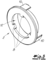
- a bayonet connection 7, 8 is realized, which is best illustrated by comparing the figures 4 and 5 can understand.
- the drive-side cylindrical tensioning element 1 is equipped with at least one receiving groove 7 for this purpose.
- the tool-side clamping element 2 has at least one engaging in the receiving groove 7 pin 8, which is based on the figure 5 can understand. In principle, the reverse procedure can also be used.
- the clamping element 1 on the drive side is equipped with the aforesaid pin 8
- the clamping element 2 on the tool side has the receiving groove 7 .
- the receiving groove 7 is formed at least in two parts.
- the receiving groove 7 has a 3-part design.
- the receiving groove 7 consists of an axial groove 7a and one here subsequent radial groove 7b together.
- a locking groove 7c at the end is also provided, into which the radial groove 7b merges at the end.
- the latching groove 7c is a blind groove running parallel to the axial groove 7a, ie a groove that is equipped with a stop at the end.
- the further basic structure then includes a particular in the 2 traceable spring 9.
- the spring 9 is a helical spring 9 surrounding the drive-side clamping element 1.
- the spring 9 or helical spring ensures that the tool-side clamping element 2 is held with its associated pin 8 in the locking groove 7c after it has been combined with the drive-side clamping element 1 .
- the drive-side tensioning element 1 is generally equipped with three receiving grooves 7 distributed over its circumference. Accordingly, the tool-side clamping element 2 has three pins 8 distributed over its circumference for engaging in the associated receiving grooves 7.
- the design is such that the tool-side clamping element 2 and the turning tool 5, 6 define a structural unit 2, 5, 6, as can best be seen from the side view or partial sectional view in FIG 2 can understand.
- the tool-side clamping element 2 in question is designed for this purpose as a holding cage 2 that at least partially radially and axially encloses the turning tool 5, 6.
- the holding cage 2 is designed in several parts, namely composed of several clamping elements 2 that can be connected to one another.
- the holding cage 2 is designed as a circular ring cage with peripheral axial webs 10 which engage over the turning tool 5 , 6 .
- the turning tool 5, 6 has recesses 11 in which the relevant axial webs 10 are arranged.
- the holding cage 2 or generally the tool-side clamping element 2 is overall and as shown in FIG figure 5 equipped with a central bore 12 into which one or the three pins 8 distributed over the circumference reach.
- the pins 8 are each aligned radially in the direction of a center point of the central bore 12 .
- the tool-side clamping element 2 can be locked by a rotary movement in relation to the drive-side clamping element 1 following the pushing movement that initially occurs.
- the pin 8 in question deviates into the locking groove 7c - acted upon by the spring 9 - so that after the bayonet connection 7, 8 has been established, the tool-side clamping element 2 and with it the rotary tool 5, 6 or the Point realized unit 2, 5, 6 is locked relative to the drive-side clamping element 1.
- the process described must be carried out in reverse.
Landscapes
- Engineering & Computer Science (AREA)
- Mechanical Engineering (AREA)
- General Engineering & Computer Science (AREA)
- Gripping On Spindles (AREA)
- Jigs For Machine Tools (AREA)
- Brushes (AREA)
- Harvester Elements (AREA)
- Cutting Tools, Boring Holders, And Turrets (AREA)
- Turning (AREA)
Priority Applications (9)
| Application Number | Priority Date | Filing Date | Title |
|---|---|---|---|
| EP22153482.9A EP4219073A1 (fr) | 2022-01-26 | 2022-01-26 | Dispositif outil rotatif à entraînement rotatif |
| TW112102871A TW202415487A (zh) | 2022-01-26 | 2023-01-19 | 旋轉機械工具 |
| AU2023200373A AU2023200373A1 (en) | 2022-01-26 | 2023-01-24 | Rotary machine tool |
| JP2023008441A JP2023109168A (ja) | 2022-01-26 | 2023-01-24 | 回転駆動可能な回転工具装置 |
| US18/100,589 US12583078B2 (en) | 2022-01-26 | 2023-01-24 | Rotary machine tool |
| KR1020230009718A KR20230115259A (ko) | 2022-01-26 | 2023-01-25 | 회전식 공작 기계 |
| CA3187796A CA3187796A1 (fr) | 2022-01-26 | 2023-01-25 | Outil de machine rotative |
| MX2023001138A MX2023001138A (es) | 2022-01-26 | 2023-01-26 | Maquina herramienta giratoria. |
| CN202310084822.1A CN116494122A (zh) | 2022-01-26 | 2023-01-28 | 能旋转驱动的旋转工具器件 |
Applications Claiming Priority (1)
| Application Number | Priority Date | Filing Date | Title |
|---|---|---|---|
| EP22153482.9A EP4219073A1 (fr) | 2022-01-26 | 2022-01-26 | Dispositif outil rotatif à entraînement rotatif |
Publications (1)
| Publication Number | Publication Date |
|---|---|
| EP4219073A1 true EP4219073A1 (fr) | 2023-08-02 |
Family
ID=80035219
Family Applications (1)
| Application Number | Title | Priority Date | Filing Date |
|---|---|---|---|
| EP22153482.9A Pending EP4219073A1 (fr) | 2022-01-26 | 2022-01-26 | Dispositif outil rotatif à entraînement rotatif |
Country Status (9)
| Country | Link |
|---|---|
| US (1) | US12583078B2 (fr) |
| EP (1) | EP4219073A1 (fr) |
| JP (1) | JP2023109168A (fr) |
| KR (1) | KR20230115259A (fr) |
| CN (1) | CN116494122A (fr) |
| AU (1) | AU2023200373A1 (fr) |
| CA (1) | CA3187796A1 (fr) |
| MX (1) | MX2023001138A (fr) |
| TW (1) | TW202415487A (fr) |
Citations (11)
| Publication number | Priority date | Publication date | Assignee | Title |
|---|---|---|---|---|
| US4661009A (en) * | 1986-03-12 | 1987-04-28 | Grentek, Inc. | Quick change coupling for machine tool arbors and the like |
| EP0319756A2 (fr) | 1987-12-11 | 1989-06-14 | Monti-Werkzeuge Gmbh | Dispositif de blocage d'outil pouvant être entraîné en rotation |
| DE4205265C1 (en) | 1992-02-21 | 1993-08-26 | Monti-Werkzeuge Gmbh, 5300 Bonn, De | Rotary brush with brush holder and circular brush - has bristles on flexible brush strip, axial arms, and radial flanges |
| DE4326793C1 (de) | 1993-08-10 | 1994-09-29 | Monti Werkzeuge Gmbh | Rotativ antreibbares Bürstenaggregat |
| EP0347429B1 (fr) | 1987-06-05 | 1996-01-31 | Werner Montabaur | Outil a brosse rotative |
| DE10030586A1 (de) | 2000-06-21 | 2002-01-10 | Bruno Schmitz Schleifmittelwer | Werkzeug |
| EP1834733B1 (fr) | 2006-03-13 | 2008-08-20 | Monti-Werkzeuge Gmbh | Unité de brosses et procédé d'usinage d'une surface d'une pièce à l'aide d'une telle unité |
| EP1859903B1 (fr) | 2006-05-24 | 2009-01-21 | Monti-Werkzeuge Gmbh | Outil rotatif pour le traitement de surface |
| GB2490549A (en) * | 2011-05-06 | 2012-11-07 | Robosynthesis Ltd | Construction set |
| EP2371487B1 (fr) | 2010-03-30 | 2014-09-17 | Monti-Werkzeuge Gmbh | Dispositif d'outil rotatif entraîné de manière rotative |
| WO2017220338A1 (fr) | 2016-06-20 | 2017-12-28 | Monti-Werkzeuge Gmbh | Dispositif à outil rotatif pouvant être entraîné en rotation |
Family Cites Families (7)
| Publication number | Priority date | Publication date | Assignee | Title |
|---|---|---|---|---|
| GB1568210A (en) * | 1976-10-29 | 1980-05-29 | Standard Telephones Cables Ltd | Bayonet connector coupling arrangement |
| ATE294670T1 (de) | 2001-06-21 | 2005-05-15 | Bruno Schmitz Schleifmittelwer | Befestigungseinrichtung |
| US8011848B2 (en) * | 2008-06-16 | 2011-09-06 | Weiler Corporation | Quick change adapter for mounting brushes |
| BR112018009323B1 (pt) * | 2015-11-10 | 2022-11-01 | Swick Mining Services Ltd | Dispositivo de conexão para uma montagem de perfuração de testemunhagem |
| DK178917B1 (da) * | 2016-05-31 | 2017-05-22 | Kadicma Aps | Bajonetkobling samt bearbejdningsenhed med sådan bajonetkobling |
| DE102018103589A1 (de) * | 2018-02-19 | 2019-08-22 | Schaeffler Technologies AG & Co. KG | Drehmomentübertragungsvorrichtung |
| PL4238451T3 (pl) * | 2022-03-04 | 2024-11-04 | Monti-Werkzeuge Gmbh | Zespół szczotki |
-
2022
- 2022-01-26 EP EP22153482.9A patent/EP4219073A1/fr active Pending
-
2023
- 2023-01-19 TW TW112102871A patent/TW202415487A/zh unknown
- 2023-01-24 US US18/100,589 patent/US12583078B2/en active Active
- 2023-01-24 JP JP2023008441A patent/JP2023109168A/ja active Pending
- 2023-01-24 AU AU2023200373A patent/AU2023200373A1/en active Pending
- 2023-01-25 CA CA3187796A patent/CA3187796A1/fr active Pending
- 2023-01-25 KR KR1020230009718A patent/KR20230115259A/ko active Pending
- 2023-01-26 MX MX2023001138A patent/MX2023001138A/es unknown
- 2023-01-28 CN CN202310084822.1A patent/CN116494122A/zh active Pending
Patent Citations (11)
| Publication number | Priority date | Publication date | Assignee | Title |
|---|---|---|---|---|
| US4661009A (en) * | 1986-03-12 | 1987-04-28 | Grentek, Inc. | Quick change coupling for machine tool arbors and the like |
| EP0347429B1 (fr) | 1987-06-05 | 1996-01-31 | Werner Montabaur | Outil a brosse rotative |
| EP0319756A2 (fr) | 1987-12-11 | 1989-06-14 | Monti-Werkzeuge Gmbh | Dispositif de blocage d'outil pouvant être entraîné en rotation |
| DE4205265C1 (en) | 1992-02-21 | 1993-08-26 | Monti-Werkzeuge Gmbh, 5300 Bonn, De | Rotary brush with brush holder and circular brush - has bristles on flexible brush strip, axial arms, and radial flanges |
| DE4326793C1 (de) | 1993-08-10 | 1994-09-29 | Monti Werkzeuge Gmbh | Rotativ antreibbares Bürstenaggregat |
| DE10030586A1 (de) | 2000-06-21 | 2002-01-10 | Bruno Schmitz Schleifmittelwer | Werkzeug |
| EP1834733B1 (fr) | 2006-03-13 | 2008-08-20 | Monti-Werkzeuge Gmbh | Unité de brosses et procédé d'usinage d'une surface d'une pièce à l'aide d'une telle unité |
| EP1859903B1 (fr) | 2006-05-24 | 2009-01-21 | Monti-Werkzeuge Gmbh | Outil rotatif pour le traitement de surface |
| EP2371487B1 (fr) | 2010-03-30 | 2014-09-17 | Monti-Werkzeuge Gmbh | Dispositif d'outil rotatif entraîné de manière rotative |
| GB2490549A (en) * | 2011-05-06 | 2012-11-07 | Robosynthesis Ltd | Construction set |
| WO2017220338A1 (fr) | 2016-06-20 | 2017-12-28 | Monti-Werkzeuge Gmbh | Dispositif à outil rotatif pouvant être entraîné en rotation |
Also Published As
| Publication number | Publication date |
|---|---|
| CN116494122A (zh) | 2023-07-28 |
| US12583078B2 (en) | 2026-03-24 |
| JP2023109168A (ja) | 2023-08-07 |
| AU2023200373A1 (en) | 2023-08-10 |
| US20230232976A1 (en) | 2023-07-27 |
| MX2023001138A (es) | 2023-07-27 |
| CA3187796A1 (fr) | 2023-07-26 |
| KR20230115259A (ko) | 2023-08-02 |
| TW202415487A (zh) | 2024-04-16 |
Similar Documents
| Publication | Publication Date | Title |
|---|---|---|
| EP0494400B1 (fr) | Outil à main avec porte-outil détachable | |
| EP2301696B1 (fr) | Combinaison d'un corps de réception et d'un insert, l'insert étant notamment développé comme support d'outil ou de pièce à usiner, un corps de réception et un insert pour une telle combinaison | |
| EP3471916B1 (fr) | Dispositif à outil rotatif pouvant être entraîné en rotation | |
| DE202010008240U1 (de) | Multifunktions-Kraftwerkzeug | |
| DE10159611C1 (de) | Spannvorrichtung | |
| EP0416610B1 (fr) | Porte-outil, notamment pour tours, avec porte-outil interchangeable | |
| DE2326546B2 (de) | Schnellspannelement | |
| DE202013103278U1 (de) | Spannvorrichtung | |
| DE102018119980A1 (de) | Spann- oder Greifeinrichtung | |
| DE69022006T2 (de) | Werkzeugspannfutter zur Ausrüstung einer drehenden Maschine, insbesondere einer Bohrmaschine. | |
| DE102017113396A1 (de) | Arbeitsspindel mit Radialklemmeinrichtung | |
| DE19818148B4 (de) | Spannvorrichtung | |
| EP0328958B1 (fr) | Dispositif d'usinage de surfaces de pièces à symétrie de révolution | |
| EP1506833A1 (fr) | Connection de buse laser | |
| DE1491029A1 (de) | Zahnaertzliches Handstueck | |
| EP2260974B1 (fr) | Support de pièce usée pour une rectifieuse plane | |
| EP4219073A1 (fr) | Dispositif outil rotatif à entraînement rotatif | |
| DE102018111044A1 (de) | Werkzeughalter | |
| DE4118376A1 (de) | Spanneinrichtung | |
| DE2647633A1 (de) | Werkzeughalter | |
| EP1782918B1 (fr) | Dispositif de serrage pour une meule, meule et élément porteur d'une meule | |
| EP2050539A1 (fr) | Roue abrasive destinée au traitement par enlèvement d'objets, en particulier de pierres, des tuiles ou analogues ou corps de roue ou anneau abrasif ou élément de fermeture pour une telle roue abrasive | |
| DE2020449A1 (de) | Schluessellos bedienbares Mehrbackenspannfutter | |
| DE202019105846U1 (de) | Elektrohandwerkzeugmaschine | |
| DE3410670A1 (de) | Spannzeugwechselanordnung an werkzeugmaschinen |
Legal Events
| Date | Code | Title | Description |
|---|---|---|---|
| PUAI | Public reference made under article 153(3) epc to a published international application that has entered the european phase |
Free format text: ORIGINAL CODE: 0009012 |
|
| STAA | Information on the status of an ep patent application or granted ep patent |
Free format text: STATUS: THE APPLICATION HAS BEEN PUBLISHED |
|
| AK | Designated contracting states |
Kind code of ref document: A1 Designated state(s): AL AT BE BG CH CY CZ DE DK EE ES FI FR GB GR HR HU IE IS IT LI LT LU LV MC MK MT NL NO PL PT RO RS SE SI SK SM TR |
|
| STAA | Information on the status of an ep patent application or granted ep patent |
Free format text: STATUS: REQUEST FOR EXAMINATION WAS MADE |
|
| 17P | Request for examination filed |
Effective date: 20231227 |
|
| RBV | Designated contracting states (corrected) |
Designated state(s): AL AT BE BG CH CY CZ DE DK EE ES FI FR GB GR HR HU IE IS IT LI LT LU LV MC MK MT NL NO PL PT RO RS SE SI SK SM TR |