EP4219219A1 - Véhicule ferroviaire comprenant un barre d'accumulateur d'énergie dotée d'un dispositif accumulateur d'énergie et d'un transformateur, procédé de fonctionnement d'un tel véhicule ferroviaire, ainsi que procédé d'assemblage d'un convoi ferroviaire, comprenant un wagon de véhicule ferroviaire - Google Patents
Véhicule ferroviaire comprenant un barre d'accumulateur d'énergie dotée d'un dispositif accumulateur d'énergie et d'un transformateur, procédé de fonctionnement d'un tel véhicule ferroviaire, ainsi que procédé d'assemblage d'un convoi ferroviaire, comprenant un wagon de véhicule ferroviaire Download PDFInfo
- Publication number
- EP4219219A1 EP4219219A1 EP22153758.2A EP22153758A EP4219219A1 EP 4219219 A1 EP4219219 A1 EP 4219219A1 EP 22153758 A EP22153758 A EP 22153758A EP 4219219 A1 EP4219219 A1 EP 4219219A1
- Authority
- EP
- European Patent Office
- Prior art keywords
- rail vehicle
- battery
- energy storage
- train
- traction
- Prior art date
- Legal status (The legal status is an assumption and is not a legal conclusion. Google has not performed a legal analysis and makes no representation as to the accuracy of the status listed.)
- Pending
Links
Images


Classifications
-
- B—PERFORMING OPERATIONS; TRANSPORTING
- B60—VEHICLES IN GENERAL
- B60L—PROPULSION OF ELECTRICALLY-PROPELLED VEHICLES; SUPPLYING ELECTRIC POWER FOR AUXILIARY EQUIPMENT OF ELECTRICALLY-PROPELLED VEHICLES; ELECTRODYNAMIC BRAKE SYSTEMS FOR VEHICLES IN GENERAL; MAGNETIC SUSPENSION OR LEVITATION FOR VEHICLES; MONITORING OPERATING VARIABLES OF ELECTRICALLY-PROPELLED VEHICLES; ELECTRIC SAFETY DEVICES FOR ELECTRICALLY-PROPELLED VEHICLES
- B60L9/00—Electric propulsion with power supply external to the vehicle
- B60L9/02—Electric propulsion with power supply external to the vehicle using DC motors
- B60L9/08—Electric propulsion with power supply external to the vehicle using DC motors fed from AC supply lines
-
- B—PERFORMING OPERATIONS; TRANSPORTING
- B60—VEHICLES IN GENERAL
- B60L—PROPULSION OF ELECTRICALLY-PROPELLED VEHICLES; SUPPLYING ELECTRIC POWER FOR AUXILIARY EQUIPMENT OF ELECTRICALLY-PROPELLED VEHICLES; ELECTRODYNAMIC BRAKE SYSTEMS FOR VEHICLES IN GENERAL; MAGNETIC SUSPENSION OR LEVITATION FOR VEHICLES; MONITORING OPERATING VARIABLES OF ELECTRICALLY-PROPELLED VEHICLES; ELECTRIC SAFETY DEVICES FOR ELECTRICALLY-PROPELLED VEHICLES
- B60L5/00—Current collectors for power supply lines of electrically-propelled vehicles
- B60L5/38—Current collectors for power supply lines of electrically-propelled vehicles for collecting current from conductor rails
- B60L5/39—Current collectors for power supply lines of electrically-propelled vehicles for collecting current from conductor rails from third rail
-
- B—PERFORMING OPERATIONS; TRANSPORTING
- B60—VEHICLES IN GENERAL
- B60K—ARRANGEMENT OR MOUNTING OF PROPULSION UNITS OR OF TRANSMISSIONS IN VEHICLES; ARRANGEMENT OR MOUNTING OF PLURAL DIVERSE PRIME-MOVERS IN VEHICLES; AUXILIARY DRIVES FOR VEHICLES; INSTRUMENTATION OR DASHBOARDS FOR VEHICLES; ARRANGEMENTS IN CONNECTION WITH COOLING, AIR INTAKE, GAS EXHAUST OR FUEL SUPPLY OF PROPULSION UNITS IN VEHICLES
- B60K1/00—Arrangement or mounting of electrical propulsion units
- B60K1/04—Arrangement or mounting of electrical propulsion units of the electric storage means for propulsion
-
- B—PERFORMING OPERATIONS; TRANSPORTING
- B60—VEHICLES IN GENERAL
- B60L—PROPULSION OF ELECTRICALLY-PROPELLED VEHICLES; SUPPLYING ELECTRIC POWER FOR AUXILIARY EQUIPMENT OF ELECTRICALLY-PROPELLED VEHICLES; ELECTRODYNAMIC BRAKE SYSTEMS FOR VEHICLES IN GENERAL; MAGNETIC SUSPENSION OR LEVITATION FOR VEHICLES; MONITORING OPERATING VARIABLES OF ELECTRICALLY-PROPELLED VEHICLES; ELECTRIC SAFETY DEVICES FOR ELECTRICALLY-PROPELLED VEHICLES
- B60L50/00—Electric propulsion with power supplied within the vehicle
- B60L50/50—Electric propulsion with power supplied within the vehicle using propulsion power supplied by batteries or fuel cells
- B60L50/51—Electric propulsion with power supplied within the vehicle using propulsion power supplied by batteries or fuel cells characterised by AC-motors
-
- B—PERFORMING OPERATIONS; TRANSPORTING
- B60—VEHICLES IN GENERAL
- B60L—PROPULSION OF ELECTRICALLY-PROPELLED VEHICLES; SUPPLYING ELECTRIC POWER FOR AUXILIARY EQUIPMENT OF ELECTRICALLY-PROPELLED VEHICLES; ELECTRODYNAMIC BRAKE SYSTEMS FOR VEHICLES IN GENERAL; MAGNETIC SUSPENSION OR LEVITATION FOR VEHICLES; MONITORING OPERATING VARIABLES OF ELECTRICALLY-PROPELLED VEHICLES; ELECTRIC SAFETY DEVICES FOR ELECTRICALLY-PROPELLED VEHICLES
- B60L50/00—Electric propulsion with power supplied within the vehicle
- B60L50/50—Electric propulsion with power supplied within the vehicle using propulsion power supplied by batteries or fuel cells
- B60L50/53—Electric propulsion with power supplied within the vehicle using propulsion power supplied by batteries or fuel cells in combination with an external power supply, e.g. from overhead contact lines
-
- B—PERFORMING OPERATIONS; TRANSPORTING
- B60—VEHICLES IN GENERAL
- B60L—PROPULSION OF ELECTRICALLY-PROPELLED VEHICLES; SUPPLYING ELECTRIC POWER FOR AUXILIARY EQUIPMENT OF ELECTRICALLY-PROPELLED VEHICLES; ELECTRODYNAMIC BRAKE SYSTEMS FOR VEHICLES IN GENERAL; MAGNETIC SUSPENSION OR LEVITATION FOR VEHICLES; MONITORING OPERATING VARIABLES OF ELECTRICALLY-PROPELLED VEHICLES; ELECTRIC SAFETY DEVICES FOR ELECTRICALLY-PROPELLED VEHICLES
- B60L50/00—Electric propulsion with power supplied within the vehicle
- B60L50/50—Electric propulsion with power supplied within the vehicle using propulsion power supplied by batteries or fuel cells
- B60L50/60—Electric propulsion with power supplied within the vehicle using propulsion power supplied by batteries or fuel cells using power supplied by batteries
- B60L50/61—Electric propulsion with power supplied within the vehicle using propulsion power supplied by batteries or fuel cells using power supplied by batteries by batteries charged by engine-driven generators, e.g. series hybrid electric vehicles
-
- B—PERFORMING OPERATIONS; TRANSPORTING
- B60—VEHICLES IN GENERAL
- B60L—PROPULSION OF ELECTRICALLY-PROPELLED VEHICLES; SUPPLYING ELECTRIC POWER FOR AUXILIARY EQUIPMENT OF ELECTRICALLY-PROPELLED VEHICLES; ELECTRODYNAMIC BRAKE SYSTEMS FOR VEHICLES IN GENERAL; MAGNETIC SUSPENSION OR LEVITATION FOR VEHICLES; MONITORING OPERATING VARIABLES OF ELECTRICALLY-PROPELLED VEHICLES; ELECTRIC SAFETY DEVICES FOR ELECTRICALLY-PROPELLED VEHICLES
- B60L50/00—Electric propulsion with power supplied within the vehicle
- B60L50/50—Electric propulsion with power supplied within the vehicle using propulsion power supplied by batteries or fuel cells
- B60L50/60—Electric propulsion with power supplied within the vehicle using propulsion power supplied by batteries or fuel cells using power supplied by batteries
- B60L50/66—Arrangements of batteries
-
- B—PERFORMING OPERATIONS; TRANSPORTING
- B60—VEHICLES IN GENERAL
- B60L—PROPULSION OF ELECTRICALLY-PROPELLED VEHICLES; SUPPLYING ELECTRIC POWER FOR AUXILIARY EQUIPMENT OF ELECTRICALLY-PROPELLED VEHICLES; ELECTRODYNAMIC BRAKE SYSTEMS FOR VEHICLES IN GENERAL; MAGNETIC SUSPENSION OR LEVITATION FOR VEHICLES; MONITORING OPERATING VARIABLES OF ELECTRICALLY-PROPELLED VEHICLES; ELECTRIC SAFETY DEVICES FOR ELECTRICALLY-PROPELLED VEHICLES
- B60L53/00—Methods of charging batteries, specially adapted for electric vehicles; Charging stations or on-board charging equipment therefor; Exchange of energy storage elements in electric vehicles
- B60L53/10—Methods of charging batteries, specially adapted for electric vehicles; Charging stations or on-board charging equipment therefor; Exchange of energy storage elements in electric vehicles characterised by the energy transfer between the charging station and the vehicle
- B60L53/14—Conductive energy transfer
-
- B—PERFORMING OPERATIONS; TRANSPORTING
- B60—VEHICLES IN GENERAL
- B60L—PROPULSION OF ELECTRICALLY-PROPELLED VEHICLES; SUPPLYING ELECTRIC POWER FOR AUXILIARY EQUIPMENT OF ELECTRICALLY-PROPELLED VEHICLES; ELECTRODYNAMIC BRAKE SYSTEMS FOR VEHICLES IN GENERAL; MAGNETIC SUSPENSION OR LEVITATION FOR VEHICLES; MONITORING OPERATING VARIABLES OF ELECTRICALLY-PROPELLED VEHICLES; ELECTRIC SAFETY DEVICES FOR ELECTRICALLY-PROPELLED VEHICLES
- B60L58/00—Methods or circuit arrangements for monitoring or controlling batteries or fuel cells, specially adapted for electric vehicles
- B60L58/10—Methods or circuit arrangements for monitoring or controlling batteries or fuel cells, specially adapted for electric vehicles for monitoring or controlling batteries
- B60L58/12—Methods or circuit arrangements for monitoring or controlling batteries or fuel cells, specially adapted for electric vehicles for monitoring or controlling batteries responding to state of charge [SoC]
-
- B—PERFORMING OPERATIONS; TRANSPORTING
- B60—VEHICLES IN GENERAL
- B60L—PROPULSION OF ELECTRICALLY-PROPELLED VEHICLES; SUPPLYING ELECTRIC POWER FOR AUXILIARY EQUIPMENT OF ELECTRICALLY-PROPELLED VEHICLES; ELECTRODYNAMIC BRAKE SYSTEMS FOR VEHICLES IN GENERAL; MAGNETIC SUSPENSION OR LEVITATION FOR VEHICLES; MONITORING OPERATING VARIABLES OF ELECTRICALLY-PROPELLED VEHICLES; ELECTRIC SAFETY DEVICES FOR ELECTRICALLY-PROPELLED VEHICLES
- B60L9/00—Electric propulsion with power supply external to the vehicle
- B60L9/16—Electric propulsion with power supply external to the vehicle using AC induction motors
- B60L9/24—Electric propulsion with power supply external to the vehicle using AC induction motors fed from AC supply lines
-
- B—PERFORMING OPERATIONS; TRANSPORTING
- B60—VEHICLES IN GENERAL
- B60L—PROPULSION OF ELECTRICALLY-PROPELLED VEHICLES; SUPPLYING ELECTRIC POWER FOR AUXILIARY EQUIPMENT OF ELECTRICALLY-PROPELLED VEHICLES; ELECTRODYNAMIC BRAKE SYSTEMS FOR VEHICLES IN GENERAL; MAGNETIC SUSPENSION OR LEVITATION FOR VEHICLES; MONITORING OPERATING VARIABLES OF ELECTRICALLY-PROPELLED VEHICLES; ELECTRIC SAFETY DEVICES FOR ELECTRICALLY-PROPELLED VEHICLES
- B60L9/00—Electric propulsion with power supply external to the vehicle
- B60L9/16—Electric propulsion with power supply external to the vehicle using AC induction motors
- B60L9/30—Electric propulsion with power supply external to the vehicle using AC induction motors fed from different kinds of power-supply lines
-
- B—PERFORMING OPERATIONS; TRANSPORTING
- B61—RAILWAYS
- B61C—LOCOMOTIVES; MOTOR RAILCARS
- B61C17/00—Arrangement or disposition of parts; Details or accessories not otherwise provided for; Use of control gear and control systems
- B61C17/06—Power storing devices
-
- B—PERFORMING OPERATIONS; TRANSPORTING
- B61—RAILWAYS
- B61C—LOCOMOTIVES; MOTOR RAILCARS
- B61C9/00—Locomotives or motor railcars characterised by the type of transmission system used; Transmission systems specially adapted for locomotives or motor railcars
- B61C9/38—Transmission systems in or for locomotives or motor railcars with electric motor propulsion
- B61C9/48—Transmission systems in or for locomotives or motor railcars with electric motor propulsion with motors supported on vehicle frames and driving axles, e.g. axle or nose suspension
- B61C9/50—Transmission systems in or for locomotives or motor railcars with electric motor propulsion with motors supported on vehicle frames and driving axles, e.g. axle or nose suspension in bogies
-
- B—PERFORMING OPERATIONS; TRANSPORTING
- B60—VEHICLES IN GENERAL
- B60L—PROPULSION OF ELECTRICALLY-PROPELLED VEHICLES; SUPPLYING ELECTRIC POWER FOR AUXILIARY EQUIPMENT OF ELECTRICALLY-PROPELLED VEHICLES; ELECTRODYNAMIC BRAKE SYSTEMS FOR VEHICLES IN GENERAL; MAGNETIC SUSPENSION OR LEVITATION FOR VEHICLES; MONITORING OPERATING VARIABLES OF ELECTRICALLY-PROPELLED VEHICLES; ELECTRIC SAFETY DEVICES FOR ELECTRICALLY-PROPELLED VEHICLES
- B60L2200/00—Type of vehicles
- B60L2200/26—Rail vehicles
-
- Y—GENERAL TAGGING OF NEW TECHNOLOGICAL DEVELOPMENTS; GENERAL TAGGING OF CROSS-SECTIONAL TECHNOLOGIES SPANNING OVER SEVERAL SECTIONS OF THE IPC; TECHNICAL SUBJECTS COVERED BY FORMER USPC CROSS-REFERENCE ART COLLECTIONS [XRACs] AND DIGESTS
- Y02—TECHNOLOGIES OR APPLICATIONS FOR MITIGATION OR ADAPTATION AGAINST CLIMATE CHANGE
- Y02T—CLIMATE CHANGE MITIGATION TECHNOLOGIES RELATED TO TRANSPORTATION
- Y02T10/00—Road transport of goods or passengers
- Y02T10/60—Other road transportation technologies with climate change mitigation effect
- Y02T10/70—Energy storage systems for electromobility, e.g. batteries
Definitions
- the present invention relates to a rail vehicle comprising an energy store and a transformer which is associated with the energy store; a rail vehicle car with an energy store and a transformer that is assigned to the energy store; a method for operating a rail vehicle with an energy storage train and a method for putting together a train composition.
- One or two-story rail vehicles that are operated both by means of external energy sources such as overhead lines and with embedded energy sources such as batteries, fuel cells or internal combustion engines are known.
- the document EP 3 878 680 discloses that the embedded energy source is directly connected to the intermediate traction circuit. DC voltage is thus fed directly from the battery into the intermediate circuit. In addition, the battery can be charged by means of the intermediate circuit.
- the embedded energy source for example the battery or the fuel cell
- the low battery or intermediate circuit voltage means that heavily constructed power lines that are difficult to lay are required. This is particularly disadvantageous for reasons of weight.
- the problem is exacerbated when the embedded energy source is arranged on a different car than the traction converter or the current consumer and thus bridges car transitions Need to become. Laying the heavily developed, heavy power lines is therefore a challenge, particularly at the carriage crossings, due to the mobile construction of the carriage crossings.
- a rail vehicle comprising a rail vehicle car, traction equipment, a high-voltage conductor, an energy storage train with an energy storage device and a transformer assigned to the energy storage device, and a rail vehicle car comprising a high-voltage conductor, an energy storage train with an energy storage device and a transformer, which is assigned to the energy storage device Solved method for operating a rail vehicle and a method for assembling a train composition.
- a rail vehicle comprising a rail vehicle car, traction equipment, a high-voltage conductor, a pantograph and an energy storage train with an energy store.
- the traction equipment includes at least one traction converter and at least one traction motor.
- the high voltage conductor electrically connects the traction equipment to the pantograph.
- the energy store can be a battery.
- the energy storage string has a transformer that is assigned to the energy storage device and is electrically connected to the energy storage device and to the high-voltage conductor.
- the high-voltage line can be dimensioned particularly advantageously.
- the battery can be charged without applying current to the traction equipment.
- the traction equipment, the high-voltage conductor and the energy storage train can be arranged on a rail vehicle car.
- the traction equipment and the energy storage train can also be arranged on separate rail vehicle carriages and connected to the high-voltage conductor.
- the traction equipment is on one rail car, the high voltage conductor is connected to the traction equipment and leads to another rail car, on which other rail car the energy storage string is arranged. It is also possible for the traction equipment to be located in the power car of a rail vehicle or for the energy storage train to be located in the power car of a rail vehicle. It is also possible for both the traction equipment and the energy storage train to be located in the power car of a rail vehicle.
- a rail car may be dedicated essentially only to the energy storage train, with no traction equipment on that car.
- this rail vehicle essentially has the task of providing energy and there are no seats for passengers in this rail vehicle.
- the rail vehicle car preferably remains passable for passengers in the interior of the rail vehicle car.
- the traction equipment may include one or more traction motors. It is also possible that the traction equipment is a Includes a plurality of traction motors, which are each arranged on a bogie, a drive axle or a wheel.
- the energy storage string may include a battery.
- the energy storage train can also include a fuel cell or an auxiliary combustion engine. It is thus possible for electrical energy to be provided by a fuel cell, which is used to operate the rail vehicle. It is also possible for diesel to be converted into kinetic energy by a diesel engine and for the kinetic energy to be converted into electrical energy by induction, with the electrical energy being used to operate the rail vehicle. It is crucial that energy can be stored by means of the energy storage train and made available as electrical energy.
- the high-voltage conductor can optionally be supplied with high-voltage alternating current via the pantograph by an external power supply and/or by means of the energy storage train.
- the rail vehicle can be designed in such a way that the high-voltage conductor is connected to an external power supply via the pantograph without any voltage-influencing components in such a way that the voltage and the frequency of the current from the external power supply can essentially be applied to the high-voltage conductor and the traction equipment.
- the high-voltage conductor and the traction equipment of the rail vehicle can be designed in such a way that they can be supplied with an alternating voltage of essentially 25 kV at a frequency of essentially 60 Hz or 50 Hz, preferably 15 kV at a frequency of essentially 16.66 Hz.
- the high-voltage conductor and the traction equipment can be subjected to voltages and frequencies which are commonly used in railway technology.
- the energy storage train of the rail vehicle can have an electrical frequency filter.
- the frequency filter can be arranged on the primary side of the battery transformer.
- the electrical frequency filter can also be arranged on the secondary side or on a separate winding of the battery transformer.
- the battery transformer can also allow a different voltage level or a different frequency for to choose the traction voltage provided by the batteries.
- a separate return current path from the negative potentials of the traction and battery transformers inside the vehicle can also be provided for operation on non-electrified routes in order to meet the requirements for interference currents there.
- the separate return current path can preferably be switched selectively, i.e. the separate return current path can be switched on. If the separate return current path is not switched on, the return current flows via the rails.
- the rail vehicle can have at least one double-decker car.
- Such a rail vehicle with a double-deck car can accommodate a particularly large number of passengers and transport them comfortably.
- the rail vehicle can comprise a multiplicity of rail vehicle cars.
- the at least one battery can be arranged in precisely one battery trolley.
- the at least one battery can also be arranged in several of the rail vehicle cars.
- a train composition can be advantageously arranged.
- the at least one battery can be arranged in precisely one battery trolley.
- a rail vehicle car of this type is essentially used for arranging the battery and is therefore a battery car.
- the battery car is passable for train passengers inside the battery car, so that train passengers arranged in front of the battery car rail vehicle car in a rail vehicle wagons arranged behind the battery wagon.
- the battery car has no seats for train passengers.
- the at least one battery can also be arranged in several of the rail vehicle carriages which, in addition to the battery, are also provided for the accommodation of passengers.
- seats for passengers are also arranged in the rail vehicle car with the battery.
- a rail vehicle car with a battery can also be passable for passengers in the interior.
- the batteries can be arranged in a power car.
- the railway car which has the battery, can comprise a lower level and an upper level.
- the battery can be arranged on the lower level.
- the upper level can have a lounge area for passengers.
- the advantageous arrangement of the battery on the lower level of the double-decker car results in a favorable weight distribution and advantageous driving dynamics when driving.
- the rail vehicle can have a display device, by means of which the charging status of the batteries can be displayed.
- the rail vehicle can be operated advantageously by such a display device, which displays the state of charge of the batteries.
- the display device can display the state of charge of a battery.
- the display device can also show the state of charge of several batteries.
- the display device of the rail vehicle can show the remaining charging time until the battery is fully charged.
- the display device It is possible for the display device to display the current remaining charging time until the battery is fully charged without taking into account the further operation and power consumption of the rail vehicle. It is also possible for the display device to display the remaining charging time until the battery is fully charged, with the further probable operation and power consumption of the rail vehicle being taken into account when calculating and displaying the remaining charging time.
- the rail vehicle can be designed in such a way that consumers of electricity in the rail vehicle that are not used for traction can be at least partially electrically connected or are connected to the battery converter.
- a rail vehicle car for a rail vehicle as described above, comprising a high-voltage conductor which can be electrically connected to traction equipment and to a current collector.
- the traction equipment includes at least one traction converter and at least one traction motor.
- the Rail vehicle wagon also includes an energy storage train with an energy store.
- the energy store can be a battery.
- the energy storage string has a transformer. The transformer is assigned to the energy store and is electrically connected to the energy store and to the high-voltage conductor.
- the energy storage string may include a battery.
- the energy storage line can also have an internal combustion engine or a fuel cell, by means of which fossil energy is converted into electrical energy. What is decisive is that electrical energy is provided by the energy storage train.
- the object of the invention is also achieved by a method for operating a rail vehicle as described above.
- the traction motor of the rail vehicle is at least temporarily and/or partially supplied with electricity from the energy storage train.
- the traction motor can be powered by a battery from the energy storage string. It is possible that the traction motor is only supplied with energy from the energy storage line during the process. It is also possible for the traction motor to be partially supplied with electric power at the same time, respectively from the energy storage string and an external power supply.
- the object of the invention is further achieved by a method for assembling a train composition, wherein a rail vehicle car as described above is added to an existing train composition.
- FIG. 1 shows a rail vehicle 22 with a battery car 23 and the associated circuit diagram.
- the rail vehicle 22 has a plurality of rail vehicle carriages 24 . Some of the rail vehicle carriages 24 have a lower level 26 and an upper level 27 on.
- the rail vehicle 22 has a current collector 1 .
- the current collector 1 is connected to a high-voltage conductor 5 of the rail vehicle 22 .
- a main switch 2 is arranged between the pantograph 1 and the high-voltage conductor 5 .
- a surge arrester 3 and several current and voltage sensors 4 are arranged between the pantograph 1 and the high-voltage conductor 5 .
- the rail vehicle 22 also has multiple traction equipment 6 .
- the traction equipment 6 each includes a first system isolator 7, a first surge arrester 8, a traction motor 11, a traction transformer 14, an auxiliary converter 10 and operating ground brushes 12 and a traction converter 9.
- the energy storage string 15 is connected to the high-voltage conductor 5 .
- the energy storage string 15 comprises a second system separator 16, a second overvoltage arrester 17, a battery transformer 18, a battery converter 19, a filter 21, a battery 20 and second operating earth brushes 12.
- the rails 13 are arranged under the rail vehicle 22 .
- the energy storage line 15 is connected to the traction equipment 6 and the pantograph 1 in a separable manner via the second system separator 16 .
- FIG 2 shows the schematic circuit diagram of the rail vehicle figure 1 (not shown) in an operating mode in which it is powered by an external power supply.
- the same reference numbers designate the same components.
- a possible second energy storage train and a possible additional traction equipment are shown in dashed lines.
- figure 3 shows the schematic circuit diagram of the rail vehicle 22 according to figure 1 in an operational mode where it is powered by a battery 20.
- the pantograph 1 is not connected to an overhead line.
- the electrical energy flows from the battery 20 through the battery converter 19, the battery transformer 18, the high-voltage conductor 5, the first system separator 7, the traction transformer 14 and the traction converter 9 to the traction motor 11.
- a possible second energy storage train and a possible additional traction equipment are shown in dashed lines.
- FIG 4 shows a possible vehicle configuration of a rail vehicle 22.
- the rail vehicle 22 has a plurality of rail vehicle carriages 24.
- One of the rail vehicle carriages 24 is designed as a battery carriage 23 .
- Some of the rail vehicle carriages have a lower level 26 and an upper level 27 .
- the rail vehicle 22 has a current collector 1 .
- the battery trolley 23 has a battery 20 .
- the rail vehicle 22 has three cars and two power cars.
- the battery car 23 is arranged in the middle of the composition of the rail vehicle 22 . Thus located on each Side of the battery car 23 each have another car and a power car.
- the battery 20 is in a single battery car 23.
- the battery car 23 with the battery 20 does not include seating for passengers.
- the battery wagon 23 with the battery 20 has a passage area so that passengers can pass the battery wagon 23 with the batteries 20 during the operation of the train composition and thus get from a wagon in front of the battery wagon 23 through the battery wagon 23 into a wagon behind the battery wagon 23 can.
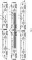
- FIG 5 shows a possible train composition of a rail vehicle 22 with six rail vehicle cars 24.
- Two of the rail vehicle cars 24 are equipped with batteries 20.
- the rail vehicle carriages 24 have a lower level 26 and an upper level 27 .
- the rail vehicle 22 has a current collector 1 .
- the two railcars 24 equipped with batteries 20 are located in the middle of the train composition.
- the two railcars 24 equipped with batteries 20 are side by side.
- the batteries 20 are thus divided between two rail vehicle carriages 24 in this train composition.
- the rail vehicle carriages 24 with the batteries 20 each have an area in which the batteries 20 are arranged.
- the rail vehicle cars 24 with the batteries 20 also have a passenger area in which passengers can stay.
- the rail vehicle carriages 24 with the batteries 20 have a boarding arrangement for passengers.
- FIG 6 shows a possible configuration of a rail vehicle 22.
- the rail vehicle 22 has several rail vehicle cars 24 on.
- the rail vehicle carriages 24 have a lower level 26 and an upper level 27 .
- the rail vehicle 22 also has a current collector 1 .
- the powered end cars of the rail vehicle 22 are equipped with batteries 20 .
- the batteries 20 are thus arranged in the power cars.
- the batteries 20 are each located in the power cars, which are each arranged at the end of the train.
- the rail vehicle cars/power cars 23 with the batteries 20 each have an area in which the batteries 20 are arranged.
- the rail vehicle cars/power cars 24 also have a passenger area in which passengers can stay. Furthermore, all rail vehicle cars have a boarding arrangement for passengers.
Landscapes
- Engineering & Computer Science (AREA)
- Transportation (AREA)
- Mechanical Engineering (AREA)
- Power Engineering (AREA)
- Life Sciences & Earth Sciences (AREA)
- Sustainable Development (AREA)
- Sustainable Energy (AREA)
- Chemical & Material Sciences (AREA)
- Combustion & Propulsion (AREA)
- Automation & Control Theory (AREA)
- Electric Propulsion And Braking For Vehicles (AREA)
Priority Applications (3)
| Application Number | Priority Date | Filing Date | Title |
|---|---|---|---|
| EP22153758.2A EP4219219A1 (fr) | 2022-01-27 | 2022-01-27 | Véhicule ferroviaire comprenant un barre d'accumulateur d'énergie dotée d'un dispositif accumulateur d'énergie et d'un transformateur, procédé de fonctionnement d'un tel véhicule ferroviaire, ainsi que procédé d'assemblage d'un convoi ferroviaire, comprenant un wagon de véhicule ferroviaire |
| CA3187058A CA3187058A1 (fr) | 2022-01-27 | 2023-01-17 | Vehicule ferroviaire comprenant un systeme de stockage d'energie ayant un dispositif de stockage d'energie et un transformateur, methode d'exploitation du vehicule ferroviaire et methode d'assemblage d'une composition de train comprenant un chariot de vehicule ferroviaire |
| US18/160,143 US20230241979A1 (en) | 2022-01-27 | 2023-01-26 | Rail vehicle comprising an energy storage system having an energy storage device and a transformer, a method of operating such a rail vehicle, and a method of assembling a train composition comprising a rail vehicle carriage |
Applications Claiming Priority (1)
| Application Number | Priority Date | Filing Date | Title |
|---|---|---|---|
| EP22153758.2A EP4219219A1 (fr) | 2022-01-27 | 2022-01-27 | Véhicule ferroviaire comprenant un barre d'accumulateur d'énergie dotée d'un dispositif accumulateur d'énergie et d'un transformateur, procédé de fonctionnement d'un tel véhicule ferroviaire, ainsi que procédé d'assemblage d'un convoi ferroviaire, comprenant un wagon de véhicule ferroviaire |
Publications (1)
| Publication Number | Publication Date |
|---|---|
| EP4219219A1 true EP4219219A1 (fr) | 2023-08-02 |
Family
ID=80122095
Family Applications (1)
| Application Number | Title | Priority Date | Filing Date |
|---|---|---|---|
| EP22153758.2A Pending EP4219219A1 (fr) | 2022-01-27 | 2022-01-27 | Véhicule ferroviaire comprenant un barre d'accumulateur d'énergie dotée d'un dispositif accumulateur d'énergie et d'un transformateur, procédé de fonctionnement d'un tel véhicule ferroviaire, ainsi que procédé d'assemblage d'un convoi ferroviaire, comprenant un wagon de véhicule ferroviaire |
Country Status (3)
| Country | Link |
|---|---|
| US (1) | US20230241979A1 (fr) |
| EP (1) | EP4219219A1 (fr) |
| CA (1) | CA3187058A1 (fr) |
Citations (3)
| Publication number | Priority date | Publication date | Assignee | Title |
|---|---|---|---|---|
| US20120090499A1 (en) * | 2009-06-15 | 2012-04-19 | Motomi Shimada | Driving system for railroad vehicle |
| DE102017213306A1 (de) * | 2017-08-01 | 2019-02-07 | Siemens Aktiengesellschaft | Energieversorgungseinrichtung für ein Schienenfahrzeug |
| EP3878680A2 (fr) | 2020-03-13 | 2021-09-15 | Hitachi Rail Limited | Système d'entraînement pour véhicule ferroviaire |
-
2022
- 2022-01-27 EP EP22153758.2A patent/EP4219219A1/fr active Pending
-
2023
- 2023-01-17 CA CA3187058A patent/CA3187058A1/fr active Pending
- 2023-01-26 US US18/160,143 patent/US20230241979A1/en active Pending
Patent Citations (3)
| Publication number | Priority date | Publication date | Assignee | Title |
|---|---|---|---|---|
| US20120090499A1 (en) * | 2009-06-15 | 2012-04-19 | Motomi Shimada | Driving system for railroad vehicle |
| DE102017213306A1 (de) * | 2017-08-01 | 2019-02-07 | Siemens Aktiengesellschaft | Energieversorgungseinrichtung für ein Schienenfahrzeug |
| EP3878680A2 (fr) | 2020-03-13 | 2021-09-15 | Hitachi Rail Limited | Système d'entraînement pour véhicule ferroviaire |
Non-Patent Citations (1)
| Title |
|---|
| "Railway applications - Supply voltages of traction systems", IEC 60850:2014, IEC, 3, RUE DE VAREMBÉ, PO BOX 131, CH-1211 GENEVA 20, SWITZERLAND, 12 November 2014 (2014-11-12), pages 1 - 37, XP082009357 * |
Also Published As
| Publication number | Publication date |
|---|---|
| CA3187058A1 (fr) | 2023-07-27 |
| US20230241979A1 (en) | 2023-08-03 |
Similar Documents
| Publication | Publication Date | Title |
|---|---|---|
| EP1186497B1 (fr) | Véhicule ferroviaire avec système d' alimentation en énergie | |
| EP3556594B1 (fr) | Procédé de fonctionnement d'un véhicule ainsi que véhicule | |
| WO2018210533A1 (fr) | Véhicule ferroviaire prévu pour effectuer une opération sur une voie ferrée | |
| DE102021116525A1 (de) | Vorrichtung und Verfahren zur elektrischen Versorgung eines Niederspannungs-Bordnetzes eines Kraftfahrzeugs, insbesondere Elektrokraftfahrzeugs | |
| EP3265358B2 (fr) | Véhicule ferroviaire, procédé d'entraînement d'un véhicule ferroviaire et procédé de fabrication d'un véhicule ferroviaire | |
| WO2003066368A1 (fr) | Vehicule pouvant fonctionner sur accumulateurs et procede pour faire fonctionner un tel vehicule | |
| EP4341123A1 (fr) | Alimentation électrique pour un véhicule ferroviaire présentant une batterie de traction | |
| DE10248438A1 (de) | Energieversorgungseinrichtung für Schienenfahrzeuge | |
| DE102019129949A1 (de) | Autowaggon | |
| EP3849869B1 (fr) | Dispositif pour entraîner une locomotive comprenant différents systèmes de fourniture d'énergie | |
| EP4219219A1 (fr) | Véhicule ferroviaire comprenant un barre d'accumulateur d'énergie dotée d'un dispositif accumulateur d'énergie et d'un transformateur, procédé de fonctionnement d'un tel véhicule ferroviaire, ainsi que procédé d'assemblage d'un convoi ferroviaire, comprenant un wagon de véhicule ferroviaire | |
| DE102016201561A1 (de) | Schienenfahrzeugverbund | |
| DE102010028004A1 (de) | Eisenbahnzug | |
| WO2024146716A1 (fr) | Alimentation électrique pour un véhicule ferroviaire présentant une batterie de traction | |
| WO2024200003A1 (fr) | Alimentation d'un véhicule ferroviaire à l'aide d'une batterie de traction | |
| EP4227143A1 (fr) | Véhicule et son procédé de fonctionnement | |
| EP4206022A1 (fr) | Système et procédé de fourniture d'énergie électrique pour véhicules ferroviaires | |
| EP3878756B1 (fr) | Système d'alimentation électrique au sol | |
| DE102024209534B3 (de) | Antriebssystem für ein Schienenfahrzeug | |
| DE102021203026A1 (de) | Fahrzeugtraktionssystem | |
| EP4328074A1 (fr) | Véhicule ferroviaire, procédé permettant de faire fonctionner le véhicule ferroviaire, ainsi qu'utilisation d'une batterie de traction | |
| EP4523942A1 (fr) | Système d'alimentation électrique pour un réseau de bord d'un véhicule ferroviaire | |
| EP4516563A1 (fr) | Véhicule ferroviaire comprenant une unité d'alimentation en énergie comprenant un transformateur de traction et une batterie de traction et procédé de charge optimisée d'une batterie de traction | |
| DE102016105614A1 (de) | Ladesystem für elektrische Verbraucher, Ladeinfrastruktureinrichtung mit einem Ladesystem und Verfahren zum Betreiben einer Ladeinfrastruktureinrichtung | |
| EP4520573A1 (fr) | Véhicule ferroviaire comprenant une batterie de traction et un convertisseur de courant ainsi que procédé de mise en marche d'un véhicule ferroviaire |
Legal Events
| Date | Code | Title | Description |
|---|---|---|---|
| PUAI | Public reference made under article 153(3) epc to a published international application that has entered the european phase |
Free format text: ORIGINAL CODE: 0009012 |
|
| STAA | Information on the status of an ep patent application or granted ep patent |
Free format text: STATUS: THE APPLICATION HAS BEEN PUBLISHED |
|
| AK | Designated contracting states |
Kind code of ref document: A1 Designated state(s): AL AT BE BG CH CY CZ DE DK EE ES FI FR GB GR HR HU IE IS IT LI LT LU LV MC MK MT NL NO PL PT RO RS SE SI SK SM TR |
|
| STAA | Information on the status of an ep patent application or granted ep patent |
Free format text: STATUS: REQUEST FOR EXAMINATION WAS MADE |
|
| 17P | Request for examination filed |
Effective date: 20231123 |
|
| RBV | Designated contracting states (corrected) |
Designated state(s): AL AT BE BG CH CY CZ DE DK EE ES FI FR GB GR HR HU IE IS IT LI LT LU LV MC MK MT NL NO PL PT RO RS SE SI SK SM TR |