EP4219251A1 - Procédé de commande pour une installation de traitement de véhicule - Google Patents
Procédé de commande pour une installation de traitement de véhicule Download PDFInfo
- Publication number
- EP4219251A1 EP4219251A1 EP23153930.5A EP23153930A EP4219251A1 EP 4219251 A1 EP4219251 A1 EP 4219251A1 EP 23153930 A EP23153930 A EP 23153930A EP 4219251 A1 EP4219251 A1 EP 4219251A1
- Authority
- EP
- European Patent Office
- Prior art keywords
- vehicle
- target
- actuators
- treatment
- movement
- Prior art date
- Legal status (The legal status is an assumption and is not a legal conclusion. Google has not performed a legal analysis and makes no representation as to the accuracy of the status listed.)
- Granted
Links
Images


Classifications
-
- B—PERFORMING OPERATIONS; TRANSPORTING
- B60—VEHICLES IN GENERAL
- B60S—SERVICING, CLEANING, REPAIRING, SUPPORTING, LIFTING, OR MANOEUVRING OF VEHICLES, NOT OTHERWISE PROVIDED FOR
- B60S3/00—Vehicle cleaning apparatus not integral with vehicles
- B60S3/04—Vehicle cleaning apparatus not integral with vehicles for exteriors of land vehicles
- B60S3/06—Vehicle cleaning apparatus not integral with vehicles for exteriors of land vehicles with rotary bodies contacting the vehicle
- B60S3/066—Vehicle cleaning apparatus not integral with vehicles for exteriors of land vehicles with rotary bodies contacting the vehicle the axis of rotation being approximately horizontal
-
- B—PERFORMING OPERATIONS; TRANSPORTING
- B60—VEHICLES IN GENERAL
- B60S—SERVICING, CLEANING, REPAIRING, SUPPORTING, LIFTING, OR MANOEUVRING OF VEHICLES, NOT OTHERWISE PROVIDED FOR
- B60S3/00—Vehicle cleaning apparatus not integral with vehicles
- B60S3/04—Vehicle cleaning apparatus not integral with vehicles for exteriors of land vehicles
- B60S3/06—Vehicle cleaning apparatus not integral with vehicles for exteriors of land vehicles with rotary bodies contacting the vehicle
- B60S3/063—Vehicle cleaning apparatus not integral with vehicles for exteriors of land vehicles with rotary bodies contacting the vehicle the axis of rotation being approximately vertical
Definitions
- the present invention relates to a control method for a vehicle treatment system with one, two or more treatment units that can be moved by controllable actuators in order to treat the surface of a vehicle.
- the invention also relates to an associated software product, a control unit and an associated vehicle treatment system.
- Vehicle treatment systems known in practice show a movement behavior for the adjustment movements of the treatment units relative to the vehicle, which appears awkward and choppy, at least in numerous movement phases.
- actuators are often involved in the movement of a treatment unit, which are often controlled completely separately. This applies in particular when an actuator has a multiple drive function and contributes to a partial movement of two or more treatment units.
- the vehicle treatment system includes one, two or more treatment units that can be moved via controllable actuators.
- the movement of a treatment unit is understood below to mean an adjustment movement relative to the vehicle.
- the actuating movement can be multi-dimensional relative to the vehicle, i.e. it can include several translatory and/or rotary components or be caused by a combination of several partial movements of rotary and/or translatory actuators.
- the treatment units can be designed in any way and perform a contact or non-contact surface treatment of the vehicle. It can be, for example, one-part or multi-part brushes (washing brushes, polishing brushes, roof brushes, side brushes, wheel washing brushes, etc.), blowers (roof dryers, side dryers) and/or mobile applicators of foams and/or fluids (high-pressure nozzles, foam nozzles). act.
- Two or more treatment units can partially or completely have a common support structure.
- two or more treatment units can be mounted together on a movable portal or a mobile carrier of the treatment facility.
- a treatment unit it is possible for a treatment unit to be moved by a group of two or more actuators. It is also possible that at least one actuator is involved in the movement of two or more treatment units.
- the treatment units are on support members with the actors connected. The geometry of the support members is known.
- the actuators are designed to move the one, two or more treatment units relative to a vehicle to be treated.
- the actuators can thus be referred to as setting actuators.
- a control method which represents a first independent aspect of the present disclosure, is described below.
- a vehicle treatment system is explained further below as a second independent aspect of the disclosure, which can be used in combination with the first aspect or independently of it.
- the aspects can be used by different people or companies and at different times and/or in different places and can therefore be used completely independently of one another.
- the aspects form a common concept, since they each alone or in combination contribute to enabling improved movement behavior for a vehicle treatment system, which in particular includes synchronized accelerations for a group of actuators that move one, two or more treatment units together.
- Such movement behavior is smooth and leads to reduced energy consumption and wear. It also enables a treatment process to be carried out particularly quickly.
- Movement behavior is preferably a dynamic plan used, which includes a number of target values for the movements of the multiple actuators in an ordered data structure, wherein the target values define at least one movement variable of the respective actuator over the duration of a treatment section.
- the dynamic plan thus frees itself from a purely momentary consideration and also from a singular actor reference.
- the motion variables can be in any form of mapping, for example in the form of a mathematically defined function or in the form of value tuples or in the form of a list or table. They each create a large number of assignments of a target value to a value of the time variable.
- the control method preferably also includes activating the actuators while the vehicle treatment is being carried out with a regulation, in particular with a status regulation, based on the target values of the dynamic plan.
- Such a control method has various advantages. It overcomes a strict connection between spatial and temporal influences when planning a treatment process.
- the schedule can be created in any way. It can particularly preferably be generated on the basis of contour recognition data from the vehicle.
- a separate planning process may exist for generating the schedule. It can be performed independently of or in combination with the control method.
- a flow chart generated by the planning method can be stored on a data medium. A stored flow chart can be read in and further processed in the control process.
- control method thus allows greater freedom in planning a treatment method.
- physical limits and predetermined operating limits of the actuators and interdependencies between the movements of the multiple treatment units can be taken into account in separate process steps, so that no contradictions in the Planning specifications for the movements of the individual treatment units arise or can be resolved.
- target spatial positions of the treatment units are initially planned in a specific sequence. This can be done fully automatically, partially automatically or manually.
- Kinematics can then (still) be planned independently of time for these target spatial positions, with which good controllability of the actuators is supported.
- This kinematics is created on the basis of parameterizable functions, which, however, are defined in relation to a process variable.
- the process variable can be understood as a quasi-time that does not correspond to real time.
- the sequence variable is suitable for assigning setting positions and the resulting values of a target path to a common variable (auxiliary variable).
- a value of this process variable can stand for a planned target state and the course of the values of the process variable can define the order in which these target states should occur.
- the process variable also defines a "distance" between these target states on a scale. However, this is not a time interval that can be measured in seconds, but a pure one calculated intermediate reference value.
- the process variable is only mapped to real time by time scaling.
- the time scaling for mapping to real time leads to a significant degree of planning freedom that is not available when using a time variable directly:
- the process variable and thus the order of the assigned target values can be positive AND, at least in sections be traversed in the negative direction.
- the gradient of the time scaling ds/dt can therefore be negative in sections.
- certain sequences or poses can be traversed backwards in order to resolve contradictions that have no option for resolution when planning purely on the basis of a time variable.
- the steps required for this can run completely automatically and in particular enable automated planning and control in the presence of single or multiple chained kinematics. This is discussed further below.
- the kinematics planned in relation to the process variable are adapted to a time variable that corresponds to real time.
- the planned movements can be carried out with such dynamics that certain predeterminable criteria are reliably met, regardless of the complexity and number of treatment units.
- Such criteria can be, for example, minimizing the total treatment time, minimizing the Energy consumption, compliance with predefined maximum or minimum speeds for the movement of a treatment unit along a vehicle contour.
- a maximum speed can be the highest speed (in terms of absolute value) in a first direction of movement.
- a minimum speed can be a maximum speed (in terms of absolute value) in the opposite direction.
- the movements of the actuators achieved using the control method according to the present disclosure can be partially synchronized or fully synchronized.
- a partially synchronized movement of the actuators in relation to an individual treatment unit occurs when the actuators involved in a multi-dimensional positioning movement of a treatment unit (group of actors involved) execute accelerations in the same time phases.
- the movement is fully synchronized with respect to the individual treatment unit if the actuators involved in its movement also perform accelerations that are proportional to one another in the corresponding time phases.
- a dynamic plan, which according to the above steps, in particular including the time scaling, can be stored as an intermediate result.
- a dynamic plan according to the present disclosure is particularly preferably designed in such a way that it on the one hand provides partially synchronized movements or more preferably fully synchronized movements for the actuators involved of each treatment unit for which planning according to the present control method was/is carried out.
- the dynamic plan preferably provides a multi-dimensional (actuating) movement for a group of treatment units, so that the actuators involved in moving the several treatment units perform accelerations in the same time phases, and continue to perform accelerations that are proportional to one another in the corresponding time phases.
- a choppy or jerky movement which often leads to increased wear and unfavorable washing results, can thus be prevented.
- Control of a treatment system according to the present method and in particular the presence of partially or fully synchronized (actuating) movements of the actuators can be detected, for example, based on the following phenomenon:
- a vehicle treatment is carried out in the vehicle treatment system.
- the instantaneous speeds of the actuators for the movement of the roof and side brushes can be determined.
- An additional obstacle is then placed on the outer contour of the vehicle (without changing its position), for example a test specimen on the hood. The obstacle should only affect the engagement area of either the side brush or the roof brush. Then the same vehicle treatment is carried out again and the current speeds are determined again.
- the portal movement is slowed down in advance (because it is known from the contour recording that the roof brush has to avoid the obstacle) and at the same time the acceleration of the lifting movement of the roof brush starts, then the movements of these actuators are at least partially synchronized. If the result is that the portal movement and the roof brush movement are also accelerated proportionally to one another while circumnavigating the obstacle, the movement of these actuators is fully synchronized.
- a jerk specification (specification for changing the acceleration) can also be provided as a movement variable for the movement plan and/or the dynamic plan in order to ensure a smooth transition between phases with different heights or achieve differently directed acceleration.
- a jerk By specifying a jerk, an even more gently changing movement behavior can be achieved, so that, for example, vibration excitation during highly dynamic treatment phases (adjusting movements with strong changes in the instantaneous speed of one or more actuators) is reduced or limited to a predeterminable level.
- the damping properties of the vehicle treatment system can be designed to be tighter, which in turn can contribute to an overall higher treatment speed.
- the movement behavior for the adjustment movements of the treatment units is no longer awkward due to the use of the present control method, but is perceptible as a smooth and fluid sequence.
- Acceleration phases can also be planned in such a way that high drive energies are only used if this is necessary for one of the specified criteria. Unnecessary abrupt accelerations (including deceleration) can thus be avoided, which has a positive effect on the energy requirement for vehicle treatment.
- a maximum path speed for a side brush or roof brush can be specified along the vehicle contour.
- any other default criteria can be set, which are taken into account in the context of the time scaling. This is discussed further below.
- phase separation ie a limitation of the planning of the treatment process to fixed phases, can be omitted.
- phase separations were often necessary to avoid contradictions in the direct planning of trajectories.
- the most common Phase separation stipulates that for one phase of the treatment process only one monotonous movement of the portal may be present (first pass forwards, first pass backwards, second pass forwards, second pass backwards).
- any vehicle contours can be treated in a touching manner even when actuators with a single or multiple chained kinematics are present, without the need for phase separation . So can For example, the cleaning of concave contours can be achieved, which are present, for example, on body parts that are drawn inward, under an alcove or under a roof rack.
- a vehicle treatment system is provided with at least one treatment unit and a plurality of controllable actuators for executing positioning movements of the treatment unit.
- the vehicle treatment system includes a controller and at least one controller. The controller transfers target values to the at least one controller, on the basis of which the controller generates one or more control signals for controlling the actuators.
- the controller includes at least one dynamic plan that defines a plurality of target values for the movements of the actuators in relation to a time variable in an ordered data structure.
- the dynamic map may be generated by the control method according to the first aspect of the disclosure. However, it can also be created in a different way or at a different location and, in particular, can be read in as a ready-made plan. For example, at vehicle treatment facilities, with which again and again matching vehicle types are washed, particularly optimized dynamic plans are generated and saved, which are read in for a specific treatment process and possibly adapted to a current positioning of the vehicle. This procedure is particularly useful for train wash systems or car and truck wash systems for cleaning fleet vehicles.
- the target values of the dynamic plan define at least one movement variable of the respective actuator over the duration of a treatment section.
- a treatment section can, for example, include front cleaning or rear cleaning with a specific treatment unit.
- a target point is defined for the treatment unit and the target values of the dynamic plan are defined for the associated group of actuators in such a way that the target point of the treatment unit follows a path during a multidimensional movement, which during surface treatment has a geometric reference to a contour of the vehicle to be treated adheres to
- the contour of the vehicle to be treated can be a surface contour or a line contour.
- the course of the contour of the vehicle to be treated preferably defines a local position in space, in particular as a translational spatial position and/or a rotational spatial position.
- the dynamic plan also defines mutually synchronized accelerations for the duration of the treatment section for each phase with a multidimensional positioning movement of the treatment unit for the actuators of the group, so that when the multidimensional positioning movement is carried out, corresponding acceleration phases of the actuators result.
- the vehicle treatment system according to the second aspect of the disclosure therefore no longer shows any phase separation between the controls of actuators that jointly move a treatment unit.
- the treatment unit requires two or three separate adjustment movements for a treatment section according to the course of the surface contour, for example a translation of the portal, a translation of a carriage on which a brush is suspended, and a rotation of an articulated joint
- the associated actuators do not execute these movements at different times, but coordinate them.
- the coordination is such that the associated accelerations of a guide actuator for the portal, a sliding actuator for the slide and a tilting actuator for the articulated joint always experience accelerations at overlapping periods of time. The same can apply to all other multidimensional movements of a treatment unit caused by a group of actuators.
- Corresponding acceleration phases of two or more actuators essentially run parallel in time. So they overlap along the time axis. Chains of acceleration phases can also be present for a number of actuators, these chains each comprising two, three or more consecutive acceleration phases. In the macro view, the chains can essentially be present for several actors in the group at the same time.
- Acceleration phases that match one another can also have exactly matching time periods in the micro perspective.
- the corresponding acceleration phases can overlap to a predetermined minimum extent, the minimum extent preferably being greater than 60%, more preferably greater than 80% of the duration of the longer acceleration phase.
- the matching acceleration phases for each of the actuators involved can begin and end at matching times.
- the matching acceleration phases can more preferably provide maximum or minimum accelerations for a plurality of the actuators involved at different points in time.
- the geometric reference of the target point in relation to the contour of the vehicle to be treated can be defined arbitrarily and depend in particular on the type of treatment unit.
- the geometric reference can be a fixed vertical distance from the vehicle surface, AND/OR a fixed distance from the vehicle surface, which is at a predetermined angle of action relative to the vehicle surface.
- the course of the path of the target point can result accordingly.
- the course of the path of the target point can in particular follow the contour course of the vehicle surface and can also be a course lying along the vehicle surface, which is possibly smoothed at places on the vehicle surface with a curvature that exceeds a predetermined limit value.
- the course of the path of the target point can follow the course of the contour of the vehicle surface with a parallel distance. Such a parallel progression can also be smoothed at places on the vehicle surface with a curvature that exceeds a predetermined limit value.
- the mutually synchronized accelerations are preferably predominantly (for at least 60% of the time, more preferably for at least 80% of the time in multidimensional movements) or exclusively (for all time shares of the multidimensional movements) are defined.
- the target values of the dynamic plan also defined accelerations that are preferably fully synchronized with one another for the actuators in the group and that continue to be proportional to one another in matching time phases. This applies in particular to such multidimensional adjustment movements with which the treatment unit is moved from a rest position at the beginning of a treatment section into a working position and/or for such multidimensional adjustment movements with which the treatment unit is moved from a working position at the end of a treatment section into a rest position is moved.
- a vehicle treatment system designed according to the second aspect of the disclosure exhibits smooth movement behavior during multidimensional adjustment movements of the at least one treatment unit relative to the vehicle. This has advantages in terms of energy consumption and the stress on the mechanical structures. Furthermore, a considerable shortening of the total duration of a treatment section can be achieved.
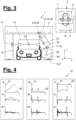
- FIG 1 shows a vehicle treatment system (1) with two or more treatment units (6,7,12) which can be moved by controllable actuators (21, 22, 23) in order to treat the surface of a vehicle (3).
- the vehicle treatment system (1) comprises a control unit (30) and a contour detection device (31) for detecting a contour of the vehicle (3) to be treated.
- the vehicle (3) is preferably arranged in a defined treatment zone (2) before the start of a treatment process. In this case, a one-off contour detection can be carried out, with the contour detection data being assumed to be constant for the entire treatment process.
- an iterative or continuous contour detection can take place. Then there is no need for a (fixed) arrangement of the vehicle (3) in the treatment zone (2).
- the vehicle is fixed in the treatment zone (2) for the duration of the vehicle treatment.
- spatial coordinates (x,y,z) of the treatment system (1) are defined on the basis of a coordinate origin which has a fixed reference to the treatment zone (2) and thus - during the duration of a treatment process - to the vehicle ( 3) has.
- the following explanations can also be applied to another form of coordinate definition, which in particular also includes a moving coordinate system.
- a relative movement takes place between the treatment units (6,7,12) and the treatment zone (2) in order to carry out the vehicle treatment.
- This can be of any design.
- the relative movement is defined in relation to the aforementioned coordinate system (x,y,z) with the fixed coordinate origin.
- Figures 1 to 3 show the vehicle treatment system (1) and its treatment units in different poses.
- a pose defines the spatial position of several (active) treatment units and preferably all (active) treatment units (which are included in the planning according to included in the present control method) at a particular moment or condition.
- the sequence of desired spatial positions can be determined in any way. It preferably takes place on the basis of contour recognition data (51) of the vehicle (3) to be treated.
- a target point can be inside or outside the physical dimensions of a treatment aggregate.
- a treatment unit with long-distance action for example a drying fan or a jet cleaning nozzle
- it can make sense to define the target point outside the physical dimensions of the treatment unit for example with a predetermined effective distance in the middle in front of a nozzle opening.
- the aim can then be to position a target spatial position of this target point on the surface of the vehicle to be treated, preferably with a fixed angle of action relative to the vehicle surface.
- a drying nozzle for example, it may be desirable for the air jet to always hit the vehicle surface at a distance of 40 cm from the nozzle opening and at an angle of about 30°.
- the aforementioned angle and distance values are given purely by way of example. Any other distance value and/or angle value can be provided.
- the planning of target spatial positions with a specified distance to the vehicle surface can result in the end - when the planned surface treatment is carried out - resulting in a path of the target point (e.g. a brush) that follows the contour of the vehicle surface with a parallel distance follows.
- the target point e.g. a brush
- the planning of target spatial positions on the surface of the vehicle to be treated can result in a path course of the target point (e.g. of the remote treatment unit) resulting in the execution of the planned surface treatment, which follows the contour course of the vehicle surface.
- the aim can be that the course of the path of the target point is smoothed compared to the course of the contour of the vehicle surface, in particular where the vehicle surface has a curvature that exceeds a predetermined limit value.
- the aforesaid paths of a destination can be generated based on the planning and control method according to the present disclosure. On the other hand, they represent an independent feature of the vehicle treatment system according to the present disclosure and could also be generated on the basis of manual creation of a dynamic plan (70), or by reading in a dynamic plan (70) generated outside of the vehicle treatment plant and its control and has been saved.
- the planning method or its steps can be carried out as a separate process, the result of which is available as an ordered and computer-readable data structure.
- the data structure can be on disk be/are stored and/or sent via an interface.
- a flow chart is preferably formed from the spatial positions of the one or more treatment units or their target points, which belong to the same state among one another. Accordingly, the setting positions in the schedule for a plurality of the actuators preferably provide setting values which, at a specific value in the sequence (i), relate to the same target state for which a pose is planned (state values).
- the vehicle (3) preferably has a known location relative to the treatment zone (2) during a treatment process. This can apply both to a fixed treatment zone (2), for example in a car wash, and to a moving treatment zone (2), such as a towing area along a car wash.
- control method according to the present invention can be used for any vehicle treatment system (1), regardless of whether the treatment zone (2) is stationary or moving, and regardless of how the treatment units (6,7,12) are designed and driven and possibly coupled to each other.
- support member In the context of the present disclosure, the terms “support member”, “target point”, “spatial position”, “actuator” have the following meaning.
- Support members are mechanically load-bearing components of a vehicle treatment facility (1) to which a treatment unit (6,7,12) is attached directly or indirectly.
- a target point is a geometric reference point for a treatment unit whose current position in space can be defined in coordinates.
- the coordinates can define a translational spatial position (position) and/or a rotational position (orientation), in particular in relation to an intended treatment zone of the vehicle treatment facility.
- An actuator is a controllable motion drive.
- An actuator can be connected to another actuator via a support member.
- control method according to the present disclosure is explained using an exemplary embodiment that includes a roll-over car wash regards.
- the steps of the method can be applied analogously to any other forms of training.
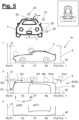
- FIGs 1 to 3 first explain different spatial positions of treatment units (6,7,12) or their target points (Z1,Z2,Z3) for three different states during a treatment process.
- FIG 5 additionally spatial positions (R) of a target point (Z1) of a side washing brush (6) relative to the vehicle (3) or the contour detection data (51) are illustrated.
- the treatment units (6,7,12) are brought into the various spatial positions by controlled movements of actuators and the associated movements of supporting members.
- the portal (4) with the guide rails for the side washing brushes (6,7) and the roof brush (12) and also the brush linkage (6c,7c) are examples of support members.
- the term support member includes any other rigid or elastic support means with which a treatment unit can be held or moved.
- At least one actuator (21, 22, 23) is provided for moving each treatment unit (6, 7, 12). Furthermore, at least one support member can be provided for each treatment unit (6,7,12). However, two or more support members and two or more actuators can also be provided for each treatment unit (6,7,12).
- a side washing brush (6) has in the example of Figures 1 to 3 two rotatable brush sections (6a, 6b) - an upper brush section (6a) and a lower brush section (6b) - these brush sections being arranged adjacent to one another in the longitudinal direction of the axis of rotation.
- An articulated joint (17) with an articulated actuator (18) is provided between the brush sections (6a, 6b), so that the lower brush section (6b) can be pivoted at an angle relative to the upper brush section (6a).
- the upper brush section (6a) is also suspended from a carriage (8) via a tilting joint (15).
- This tilting joint (15) allows the upper brush section (6a) and thus also indirectly the lower brush section (6b) to be swiveled out in relation to the vertical direction, for which purpose a tilting actuator (16) is provided on the tilting joint.
- the carriage (8) can be displaced on a running rail of the portal (4) in a first horizontal direction (transverse direction y of the vehicle treatment facility), for which purpose a sliding actuator (9) is provided.
- the rail for the side brushes is attached to a portal (4) of the vehicle treatment facility, the portal (4) being able to be guided along a longitudinal guide in a further horizontal direction (longitudinal direction x of the vehicle treatment facility).
- a portal drive/guide actuator (5) is provided for this.
- the relevant geometric references are known for the carrier, the running rail, the carriage, the tilting joint, the upper brush section, the articulated joint and the lower brush section, ie for example their size and possibly their load-dependent deformation behavior.
- a setting position can in particular be a rotational setting position and/or a translatory setting position.
- a (desired) spatial position (R) of the target point (Z1, Z2, Z3) of a treatment unit (6,7,12) is known, at least one pose (posture) for the parts of the treatment system that contribute to the movement of the treatment unit can be calculated from this .
- the pose is defined by the geometric references of the supporting members involved and the setting positions of the actors involved. From a desired target spatial position (Ri) of a target point, at least one suitable pose can be calculated in each case, through which this target spatial position (Ri) can be reached, and an associated adjustment position (Pi) can be determined accordingly for one or each actuator involved .
- the treatment unit (6,7,12) will actually assume that spatial position (R) that is defined as the target spatial position for the target point (Z1).
- the spatial position (R) of the side washing brush (6) and in particular its target point (Z1) is considered as an example.
- the tilt joint (17) and the articulation joint (18) are only in the stretched position. Cases will be discussed later (as you can see in figures 2 and 3 shown) in which the tilt joint (18) and/or the articulation joint have a different posture.
- the movement of the target point (Z1) depends on the setting positions of the portal drive/guide actuator (5) and the slide actuator (9) and the tilt actuator (17). In the following, these are interpreted as first actuator (21), second actuator (22) and third actuator (23), for example. However, the further representation can be transferred to other actuators as desired.
- the time variable (t) should correspond to real time and be defined in milliseconds or seconds, for example.
- a target trajectory indicates which control value (e.g. in degrees or millimeters) an actuator should achieve as a target value at each planned point in time.
- the target speed indicates which current speed (e.g. in rad/s or m/s) the actuator should reach at each planned point in time as a target value.
- the target acceleration indicates which instantaneous acceleration (e.g. in rad/s 2 or m/s 2 ) the actuator should achieve at each planned point in time as a target value.
- the parts (movement variables) of the dynamic plan (70) can be in any form that can be processed by a computer, in particular as (mathematical) functions and/or (individual) values in an ordered data structure such as an array, a vector, a table, etc.
- the dynamic plan (70) can include a complete treatment process with one or more treatment cycles. Alternatively, it can be present separately for different treatment cycles and/or only be generated gradually for specific time periods, for example if the contour is detected continuously or iteratively.
- the time variable and the setpoints can be present as continuous variables or as discrete variables.
- the dynamic plan is available as an ordered data structure for a large number of points in time (values of the time variable). includes the corresponding target values for the target trajectory, the target speed and the target acceleration of the actuators.
- the target values can be present for each point in time, for example one set of target values per millisecond, or only for some of the possible points in time.
- the setpoints from the dynamic plan can preferably be transferred to a (state) controller (32), which generates corresponding control signals directly or indirectly based on the setpoints in order to control the actual movement of one or more actuators (21,22,23) and in particular to settle.
- a (state) controller 32
- which generates corresponding control signals directly or indirectly based on the setpoints in order to control the actual movement of one or more actuators (21,22,23) and in particular to settle.
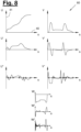
- Contour detection data (51) are entered in the diagrams as an example Cross-sectional contour (upper diagram) and two courses of a side contour (middle diagram) as well as courses of an inclination angle at two altitudes (lower diagram). up in figure 5 exemplary reference points (52) on the outer contour of a vehicle (3) are shown, to which the contour detection data (51) in the diagrams can belong.
- the middle diagram shows an example of how different spatial positions (R) of the side washing brush (6) can be planned in a specific order (i) on the basis of the contour detection data (51) of the vehicle (3).
- R spatial positions
- i the contour detection data
- the side washing brush (6) is aligned exclusively vertically, so that the reference points (Z1, Z2) lie directly one above the other in the plan view.
- a target point (Z1, Z2, Z3) is defined as a geometric reference point of the treatment unit (6,7,12) for at least one treatment unit and preferably each treatment unit (6,7,12), whose (current) spatial position (R) in turn can be defined in coordinates (x,y,z).
- the planning can be done manually, partially automated or fully automated based on the contour detection data (51) of the vehicle (3) to be treated. Planning can be relative to a Treatment zone (2) of the vehicle treatment facility (1) take place, which in figure 5 shown for easy comprehension. Alternatively, it can take place in relation to one or more characteristic points (so-called markers) on the vehicle (3) and thus independently of an external absolute coordinate system.
- This planning is possible for any number of treatment units, which can each be active individually, overlapping in time, or at the same time, and in particular can be in an active position relative to the vehicle.
- Target spatial positions (Ri, R0, R1, R2, ...) are automatically planned for several steps (0,1,2,3,%) in the order (i).
- positions for the side brush (6) are determined, for example, with a predetermined grid along the x-coordinate or along the contour line, which are spaced apart from the contour line (53) by a predetermined amount in the normal direction.
- any other planning method can be used.
- the planning preferably takes place in the form of a target spatial position for the target point (Z1/Z2).
- the aforementioned grid is not mandatory. It only serves to make the procedure easier to understand.
- adjustment positions (Pi, P0, P1, P2,%) of at least one actuator (21,22,23) involved in the movement of the (respective) target point (Z1) are determined on the basis of a known geometry Vehicle treatment system (1), so that the adjustment positions (Pi, P0, P1, P2, ...) with the target spatial positions (Ri, R0, R1, R2, ...) of the target point (Z1) correlate.
- Determining the positioning positions includes retrieving a previously stored data set, for example based on a type identification of the vehicle to be treated and an adjustment to the determined position of the vehicle (3) in the present treatment situation.
- default criteria for individual or combined poses or states for the treatment method can be defined.
- the specification criteria can only be defined differently for specific sections of the vehicle treatment and/or in sections. For example, a maximum web speed of a side or roof roller along a vehicle window can be set to a separate limit value.
- Target points are particularly preferably defined for a plurality of treatment units, in particular for all (active) treatment units, and their current spatial positions (R,L) in coordinates (x,y,z) are determined for the creation of a flow chart (50), which in particular refer to the same coordinate system.
- This makes it possible for spatially coordinated target positions (Ri,Li) of these multiple target points (Z1,Z2) to be planned as a target pose sequence (K).
- K target pose sequence
- a schedule can be drawn up individually for each vehicle to be treated in the vehicle treatment facility (1). Alternatively or additionally, it is possible to save a flow chart and read it in again. For example, schedules can be predefined for different vehicles or vehicle types and read back in when an upcoming treatment process based on contour recognition is required specific vehicle or a specific vehicle type has been identified.
- a movement plan for handling the vehicle is created, which includes a target path (U,V,W), a target positioning rate (U',V',W') and preferably a target positioning rate change (U",V",W ") for the majority of the actuators (21,22,23) as (mathematical) functions in relation to a process variable (s). This process is in the transition from figure 6 on figure 7 explained.
- figure 6 shows the already in figure 5 for the first actuator (21) outlined flowchart (50) in a separate diagram.
- the sequence (i) is shown here on the abscissa axis (41) and an associated value of the setting position (Pi) is shown with a corresponding distance along the ordinate axis (x).
- figure 7 shows a target path (U) for the first actuator (21).
- the process variable (s) is shown here on the abscissa axis (40).
- Target values for a position of the first actuator are specified on the ordinate axis, which correlate with the setting positions (Pi) along the x-axis.
- the process variable (s) can be defined in any way.
- the values (0,1,2,%) of the order (i) could be arranged on a continuous scale, choosing the same unit distance between each value.
- process variable (s) can be specified manually by a planner or by another program part.
- the target path (U,V,W) is preferably defined in length sections of the sequence variable (s), ie for a range [s_min ⁇ s ⁇ s_max] as a function that is suitable for the target positions (Pi) of the sequence plan ( 50) to achieve. It can be specified that each setpoint position (Pi) or each associated control value (61) can be reached exactly. As an alternative or in addition, control values (62) can be planned, which can be achieved if a tolerance (T) is observed.
- a control value (61) for exact achievement and for another part of the control positions (Pi) a control value (62) for achieving a tolerance can particularly preferably be specified - depending on the position within a treatment process.
- the tolerance can be defined uniformly or differently for different control values (62).
- Functions that can be parameterized are selected with which the target path is defined (in sections).
- a setpoint adjustment rate (U′) and preferably a setpoint adjustment rate change (U′′) are determined by derivation.
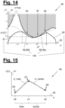
- the boundaries of the two sections are at the s-values of three consecutive adjustment positions (Qi).
- the abscissa axis (40) shows in figure 15 the process variable (s), the ordinate axis (41) shows the absolute value of the setting position (Q) and consequently the functional value of the setpoint path (U).
- the total of eight parameters (k0, k1, k2, k3, 10, 11, 12, 13) of the two function sections U_left, U_right for the target path can be determined using an equation system with eight boundary or transition conditions. Depending on the application, these conditions can be suitably defined.
- the function should be continuous and the control value of the actuator should reach the transition point Q1.
- the transition point Q1 it should apply that this point is passed through with a constant change in the setting rate.
- the actuator At the end position, the actuator should return to a specified end control value with a final control rate and a change in the final control rate.
- the parameters (k0, k1, k2, k3, 10, 11, 12, 13) are fixed and suitable functions are available for the two sections (left, right) as target path (U), target Positioning rate (U') and target positioning rate change (U") defined for the motion plan.
- a target jerk (U′′′) can also be defined.
- This method can be carried out for several or all actuators (21, 22, 23) in order to obtain a corresponding number of target paths (U,V,W), target positioning rates (U',V',W'), target Positioning rate changes (U", V", W") to be defined.
- the method can also be carried out for an arbitrarily long chain of sections. A section can be defined between two consecutive positioning positions (Pi).
- the selectable function types can basically be mixed as desired between the target paths (U,V,W) and their sections.
- a function type can be selected in any way.
- the vehicle treatment system or its controller has a set of rules and/or a set of function templates for specific parts of the treatment process
- the set of rules or the function template provides certain characteristic adjustment positions according to type and sequence for individual or all actors involved and predefined suitable functions and associated boundary or transition conditions between these intended adjustment positions.
- the exact location of the characteristic adjustment positions can be calculated as a function of a contour detection of the vehicle.
- the boundary and transition conditions can be calculated according to height and the parameters of the predefined functions can be determined.
- the rule set and the function templates can be predefined by the manufacturer for certain vehicle types and/or special body shapes in order to achieve particularly good washing performance.
- the aforementioned steps for forming a target path (U,V,W) and the associated target positioning rate (U',V',W') and target positioning rate change (U",V",W") can be used for two or more and in particular all actuators (21,22,23) are applied.
- figure 8 illustrates a movement plan (60), in which for the first actuator (20) according to the above example, ie for the portal drive / guide actuator (5), and the second actuator (21), ie the carriage drive / slide -Actuator (6) depending on a target path (U, V) is defined in sections by suitable functions. Furthermore, a target path (W) for a third actuator (23), ie the inclination actuator (17), is shown as an example. For reasons of better representation, the curves shown do not exactly match the target spatial positions (Ri) and the adjustment positions (Pi) derived from them. It is relevant here to get an impression of the information content of the parts of the movement plan (60).
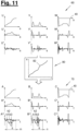
- FIG 11 illustrates how the dynamic plan (70) is formed from the movement plan (60) by stretching and/or compressing by means of time scaling.
- Time scaling results in a mapping of process variable (s) to time variable (t).
- process variable (s) to time variable (t).
- t time variable
- the physical limits and/or operating limits are included in this adaptation.
- FIG 9 explains this scaling/adjustment in the form of a time scaling plan (80).
- the time variable (t) is shown there on the abscissa axis and the sequence variable on the ordinate axis (41).
- the processing speed of the quasi-time (sequential variable s) is sometimes accelerated, sometimes slowed down, according to the slope ds/dt in the time scaling plan (80).
- the value of this function indicates at which point in time (value of the time variable (t)) an assigned value of the process variable (s) is to be taken into account.
- the slope of the time scale thus indicates at which step rate (ds/dt) the movement plan should be run through. The higher the step rate, the faster the movement plan will go through - the lower the step rate, the slower the movement plan will go through.
- a monotonously increasing function for the time scaling has the advantage that it is easier for the system designer to understand.
- the methods according to the present disclosure can also be used with functions that are not monotonic and, in particular, have a negative slope in at least one section (82'). This means that at this point at least part of the dynamic plan is first run through backwards and then forwards again. This makes it possible in particular, to provide a planning for the movement of actors with multiply linked dynamics.
- the time scaling factor (F) can theoretically be chosen as a single value for the entire execution time. Alternatively and preferably, it is set separately for specific periods of time.
- the time scale factor (F) can be determined or set in any way. It is preferably chosen on the basis of the physical limits or operating limits that exist for the respective actuator or the movement of the respective process element. In particular, this can be a physically conditioned maximum actuator speed U°max or a maximum actuator speed U°°max defined by the manufacturer/user, a maximum actuator acceleration U°°max and/or a maximum actuator jerk U°°°max.
- Constant scaling in sections can be favorable for those parts of the treatment process in which (for the majority or all actuators) relatively small changes in acceleration are to be expected, because constant scaling can lead to an increase in jerk behavior, which in the aforementioned
- sharing the treatment process does not have to mean a disadvantage.
- the advantage of constant scaling is that it can be calculated comparatively quickly.
- time scaling (at least in sections) is carried out as a variable scaling.
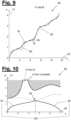
- a preferred procedure for determining a variable time scaling is based on figure 10 explained.
- the web speed s° is defined as the first derivation of the sequence variable s according to time (not according to the sequence variable!).
- process variable s is not a geometric reference variable in space, but a quasi-time.
- path speed s° therefore also has no direct relation to a geometry. It simply designates the gradient ds/dt with which the setpoint values defined in relation to the process variable s are run through.
- the target path (U,V,W) is now derived at least twice, preferably three times, based on time (not based on the process variable!) and in relation to the web speed (s°) and the web acceleration (s°°) and any set to the path jerk (s°°°):
- variable scaling is determined in a state space over a range of the process variable (s) by integration, based on boundary conditions at the limits of the range and preferably taking into account default criteria for the dynamics.
- the range of the process variable(s) and the default criteria can be chosen arbitrarily (jointly or independently of one another).
- a maximum actuator jerk can also be defined and taken into account.
- the instructions for action presented below can be transferred accordingly to the consideration of the actuator jerk.
- a mathematical implementation of the two aforementioned modifications is omitted below for reasons of better comprehensibility.
- a path acceleration s°° is preferably defined as a function that can be integrated and parameterized at least twice. In the simplest case, this is a constant value or a variable with a value range from 0 to s°°max. It is explained further below that the path acceleration can also be calculated as a variable value from the general dynamic equation.
- the web acceleration s°° is integrated twice, taking into account predetermined limits for the web speed (s°max, s°min) and preferably predetermined limits for the web acceleration (s°°max, s°°min) in order to determine the parameterization from this and to calculate the process variable (s) as a (mathematical) function of the time variable (t) (see result figure 9 ).
- figure 10 shows the intermediate result after the first integration.
- the limits of the path speed s°max, s°min and the path acceleration (s°°max, s°°min) from the maximum and minimum actuator speed (U°max, U°min) and the maximum and minimum actuator acceleration (U° °max, U°°min) have been determined. This is substantiated below with a mathematical explanation, which, however, only represents one of many possible calculation methods.
- An absolute upper limit in the state space diagram (90) according to figure 10 is specified for each value of the process variable (s) by a maximum web speed (s°max), which is calculated from the maximum actuator speed U°max using the above formula.
- the maximum actuator speed U°max can, for example, be set to a certain value as an operating limit. The shaded area of the state space must therefore not be traversed. In some areas, however, the absolute upper limit could reach infinity (theoretically). It is also possible to define an upper limit value (s°max, fix), which must not be exceeded overall. This one is in figure 10 shown as an example.
- a minimum web speed (s°min) is not plotted for reasons of simplification. It would have a profile that is a mirror image of the maximum web speed (s°max) in relation to the abscissa axis (40).
- the path speed (s°) can only assume zero or positive values, so that the minimum path speed (s°min) can be dispensed with.
- part of the vehicle handling first forwards, then backwards, and to run forwards again, for example to clean a certain part of the vehicle particularly intensively, or to have a certain treatment unit perform a movement that requires at least one actuator in a chained dynamic to perform a temporary backward movement (cf. section 82 ⁇ in figure 9 and explanations of movement sequences according to figure 13 ). It is therefore entirely possible and, in some applications, useful or even necessary to take both a maximum web speed and a minimum web speed (s°min) into account. The present statements then apply analogously.
- the maximum and minimum path speeds only represent limits that should not be exceeded. It is entirely possible to time scale all sections based on these maximum values. This can result in a course of the path speed s°, which is shown in figure 10 essentially follows the course of the sections s°max (variable) and possibly s°max, fixed. However, it has turned out to be advantageous that a different form of time scaling offers advantages, in particular that the maximum path acceleration s°°, any maximum path jerk or other boundary or transitional conditions are also taken into account. Various explanations are given below for this purpose.
- the boundary conditions can be chosen arbitrarily.
- the process variable (s) and the web speed (s°) have a specified start value.
- both start values are zero.
- any other known starting values could be provided.
- this value is the determined maximum value of the path acceleration (s°°max).
- a maximum web acceleration could be determined from the specification of a maximum web jerk. It is explained further below that a default value for the acceleration can also differ locally and can be calculated in particular from the general dynamic equation for the vehicle treatment system (1).
- this specified value is the minimum path acceleration (s°°min), which is calculated from the minimum actuator acceleration U°°min (braking power).
- variable scaling (82) A resulting overall course of the variable scaling (82) is shown as an example in figure 9 shown.
- the variable scaling can include at least one section (82') in which there is a negative gradient (s° ⁇ 0). At such points, when the process variable (s) is mapped to the real time (t), some of the target values are run through in the negative direction of the process variable (s) (see explanations above). A monotonically increasing course of the variable scaling (82) is assumed below for reasons of easier comprehension.
- the chain of images in turn preferably includes forward integrals (91, 96a) and backward integrals (92, 96b) of the maximum path acceleration (s°°max) based on boundary and transition conditions.
- s°°max maximum path acceleration
- F constant time scaling factor
- the course of the maximum web speed (s°max, s°max, fix) for the corresponding section of the sequence variable (s) can often be used as a substitute curve.
- an intermediate intersection section can be defined with which the closest equivalent curve to the maximum web speed (s°max) can be maintained without exceeding the other physical and operating limits. The determination of such an intermediate section of intersection is explained further below.
- variable scaling can each be used separately or in combination. Furthermore, a variable scaling can also be determined in a different way than by the above-mentioned integration.
- a first scaling type for example constant scaling
- a further scaling type for example constant scaling
- the dynamic plan (70) only includes a target trajectory (A,B,C).
- the dynamic plan (70) can be in the form of an ordered data structure and can be stored in physical memory. It may alternatively be in the form of a stream of data that is progressively generated and is processed.
- the dynamic plan is particularly preferably stored as an array, a table or a similar data structure and not only covers a current point in time in real time, but also a time segment lying in the future. This applies in particular to a dynamic plan that is stored in the control system or the control unit of the treatment facility.
- a dynamic plan can be saved in sections or in its entirety as a digital object. For example, it is possible to have the control method according to the present disclosure executed by a computing device that is separate in terms of time and/or location from the vehicle treatment system.
- the target speed (A°,B°,C°) and/or the target acceleration (A°°,B°°,C°) can be specified explicitly. Alternatively or additionally, they can be determined by deriving them from the target trajectory (A,B,C). This determination can be made at any time.
- a controller of the treatment system can set the target speed (A°,B°,C°) and/or the target acceleration (A°°,B°°,C°°) before the transfer to one or more controllers (32 ) for the actuators themselves and calculate in particular by derivation (differentiation).
- the target speed (A°, B°, C°) and the target acceleration (A°°, B°°, C°) can be determined by a controller (32) of the actuator to be addressed.
- a separate controller (32) can be provided for each actuator.
- a controller (32) can be provided jointly for two or more actuators.
- a preferred embodiment provides that the dynamic plan is generated completely with the target trajectory, target speed and target acceleration and that the respective target values that belong together are transferred together to a controller for each point in time of the control. This is advantageous in order to utilize the maximum accelerations of the actuators.
- the dynamic plan is generated from the movement plan by local stretching and/or compression using time scaling (82, 82).
- the stretching and/or compression does not usually lead to a change in the level of the target values of the target path (U,V,W), but only to a different distribution of the target values of the target path (U,V ,W) versus the time variable (t).
- the result of time scaling is therefore usually different from the result that would be achieved by simply accelerating a wash program. In particular, no overshoot is caused by the time scaling.
- the dynamic plan can be generated before or during the execution of a vehicle treatment. It can be carried out in sections for a specific range of the process variable (s) / the time variable (t) or overall for an entire treatment process or its cycles.
- the scaling means that the abscissa axis (40), which shows the process variable (s) in the movement plan (60), is replaced by the time variable (t) in the dynamic plan.
- the target values for the movement of the actuators (21,22,23) are expressed in the dynamic plan based on the target trajectories (A,B,C), which are mapped as a function of the time variable (t). Additional target values are defined for the target speeds (A°,B°,C°) and preferably the target accelerations (A°°,B°°,C°°). As an alternative or in addition, target values could be defined for a target jerk.
- the graphical profile of the setpoint trajectory (A,B,C) is clearly similar to the profile of the associated setpoint path (U,V,W), but is stretched or compressed locally in the direction of the abscissa axis (40). Where the gradient (ds/dt) of the scaling (81,82) is high, the movement plan is run through comparatively faster, so that at these points the target trajectory (A,B,C) of an actuator (21,22,23 ) appears compressed compared to the associated target path (U,V,W).
- the movement plan is run through comparatively more slowly, so that the target trajectory (A,B,C) of an actuator (21,22,23 ) appears stretched compared to the associated target path (U,V,W).
- the setpoint accelerations (A°°, B°°, C°°) reveal corresponding points in time (ti) at which accelerations of the actuators (21,22,23) begin and end up. For reasons of simplification, these corresponding points in time (ti) are only given for part of the time axis (t) and purely as an example.
- the simultaneity of the accelerations for the multiple actuators (21, 22, 23) leads to a particularly gentle and smooth movement behavior, in particular with (all) multidimensional adjustment movements of a treatment unit.
- the simultaneity can result as an indirect consequence of the pose planning and the preferably uniform time scaling (80).
- acceleration phase (ki) between each two points in time (ti). It turns out that the acceleration phases (ki) in the course of the target acceleration (A°°) for the first actuator and the acceleration phases (ki) in the course of the target acceleration (B°°) for the second actuator match. They essentially run at the same time.
- a particular advantage of the dynamic plan according to the present disclosure is that it can also be generated as a common dynamic plan for a plurality of actuators that are subject to kinematics linked once or several times.
- the dynamic plan can define mutually synchronized accelerations (A°°,B°°,C°°) during the duration of the treatment section for each phase with a multidimensional adjustment movement of the treatment unit for these actuators, so that when the multidimensional actuating movement matching acceleration phases (ki) for the multiple actuators (21,22,23) result, even if they contribute to the movement of multiple treatment units.
- the result according to the example of figure 11 can already result if only one of the movement variables target trajectory, target speed, target acceleration or target jerk is defined, since these variables can be converted by differentiation/integration. It is therefore possible, for example, to actually define only one or two of these movement variables in the dynamic plan (70) or to transfer them to a controller (32).
- a particularly precise implementation of the desired multidimensional actuating movements and/or maximum utilization of the possible power are favored if at least two and preferably three of the movement variables are defined in the dynamic plan and transferred to a controller (32), in particular a state controller.
- the separation of the planning process into a movement plan and a dynamic plan also offers the following advantages:
- suitable spatial positions of the associated target points (Z1,Z2,Z3) can be defined in a specific order (i) for all relevant states that the treatment units should assume during vehicle treatment, from which associated positioning positions (Pi) of the actuators ( 21,22,23) can be deduced.
- This planning step does not require any consideration of the physical limits or Operating limits of the actuators, so that a targeted approach with a quickly implementable and robust processing is enabled.
- This processing process can be carried out manually or, preferably, partially or fully automatically.
- target paths can be created in the movement plan for the majority of actuators (21,22,23) with simple means (function selection, parameterization, solution of simple equation systems with boundary conditions), which also does not yet take into account the physical Limits or operating limits of the actuators required.
- any couplings of the kinematics between the actuators can flow into this planning step, so that the movement plans can already be partially or completely synchronized with one another (in relation to a sequence variable s).
- There is a coupling of the kinematics between two actuators if they participate in a chained kinematics for a treatment unit. In this way, consistent planning can be carried out, at least for simply linked kinematics.
- additional setting positions (Pi*) can be inserted as supplementary support points, particularly in a target path (U) for a first actuator (21) at such values of the process variable (s), where a specific target spatial position of another actuator (22,23) is defined. This is particularly helpful when the first actuator and the other actuator are kinematically coupled.
- FIG 5 Some additional positioning positions (Pi*) of the portal drive/guide actuator (5) are shown as examples, which are inserted as support points, for example because there is a target spatial position for the target point (Z3) of the roof brush (12) or for the target point (Z1 ) of the upper brush section (6a) would be useful.
- the desired values (62) derived from these additional support points (Pi*) in the desired path (U) according to FIG figure 7 are intended to be achieved with a certain tolerance.
- target spatial positions (R,L) for at least one treatment unit and in particular for two or more treatment units (6,7,12) or their target points only for certain areas in the treatment process, i.e. a minimum definition set Desired spatial positions, preferably as a function of the contour detection data (50).
- these can be areas in which there is a major change in the vehicle contour or concave/convex curvatures, as well as at the beginning and end of essentially flat contour areas.
- the number of target spatial positions to be planned can thus be reduced to a minimum for each treatment unit.
- Corresponding additional spatial positions can be determined for the other target points and associated additional target positions (Pi*), from which corresponding additional support points in the target paths of the associated actuators can then be derived.
- An associated value of the process variable (s) is determined (or set) and a pose (posture) for several or all treatment units (6,7,12) is particularly preferably determined or defined for each target spatial position in the minimum definition set.
- a pose (posture) for several or all treatment units (6,7,12) is particularly preferably determined or defined for each target spatial position in the minimum definition set.
- an overall state of all (active) actuators can be determined or defined for the pose in order to provide associated setpoint values (61, 62) in the setpoint paths.
- setspoint values 61, 62
- the target paths can also be planned independently of one another. This can be particularly advantageous when there is no kinematic coupling for two or more actuators. Because in this case there tend to be fewer target positions (Pi), so that processing can take place with lower demands on computing power.
- the movement plan (60) preferably includes an exact kinematic definition of the movements of the actuators (21, 22, 23) for carrying out the vehicle treatment and is suitable for being run through at an adjustable processing speed.
- the processing speed is defined by the time scaling in such a way that the movements of the actuators can take place with freely selectable default criteria, ie for example using the maximum acceleration on the one hand and minimizing the energy consumption on the other. Furthermore, the time scaling can be used to ensure that the movements of the actuators do not exceed the physical limits and the specified operating limits without the need to define a phase restriction. Especially when the kinematics are linked twice or more, contradictions between the individual movements of these actuators and the resulting poses can be resolved within the framework of time scaling.
- the dynamic plan generated on the basis of the time scaling thus allows all actuators (considered in the planning) to be controlled with the ideal control parameters (current target position according to target trajectory, current target speed, current target acceleration) for each moment of vehicle handling in accordance with the default criteria.
- the ideal control parameters current target position according to target trajectory, current target speed, current target acceleration
- this is possible without a phase separation or a separation of the control/regulation for individual actuators being necessary for this.
- the entire treatment system (1) can be operated with any number of treatment units and actuators with a holistic control or regulation of all partial movements, with all of the boundary conditions being observed at all times.
- the entire treatment process can be carried out and visualized completely in a simulation environment.
- the vehicle treatment can be fully anticipated for all parts of the vehicle (3) for which a contour has already been recorded (51), both with regard to the current states of all actuators and treatment units and with regard to the duration of the treatment.
- the states can be defined according to the dynamic plan (70), at least with regard to the target trajectory (A, B, C).
- the target speed (A°, B°, C°) and/or the target acceleration (A°°, B°°, C°°) is preferably additionally specified.
- this content can be present in a different form and in particular in an ordered data structure.
- this can be: mathematically defined functions, approximation curves of such functions, arrays, tables, vectors.
- a particularly preferred embodiment provides that at least the dynamic plan (70) is present in such a form that for each time interval in which the control method is carried out, for example for each time step of the control time, particularly preferably for each millisecond, there is a value for the target trajectory (position or angle), and preferably also for the setpoint speed (translational or rotational) and/or the setpoint acceleration, these values being transferred to a controller for the respective actuator (21,22,23).
- the dynamic plan includes, in a common data structure, setpoint values for a number of actuators, in particular for a group of actuators which are involved in the movement of a treatment unit.
- the dynamic plan includes, in a common data structure, target values for a number of actuators, which are subject to single or multiple chained kinematics for the movement of at least two treatment units.
- the control of the actuator movement is converted into an actual movement according to the dynamic plan, so that the actual trajectory corresponds to the target trajectory or is approached.
- the controller can have any training. It can be a cascade controller, for example.
- the controller is particularly preferably a status controller.
- the controller (32), in particular the cascade controller or state controller, is therefore set up to control the actuator (21,22,23) in such a way that the actual trajectory, and preferably also the actual speed and/or the actual acceleration follow target values.
- the controller (32), in particular the cascade controller or status controller, can compensate for any discrepancies between the actual values and the desired values by appropriate control interventions.
- Figure 12 illustrates a way of creating an intermediate intersection section (96) as a variable time scale section (82).
- the curves of the forward integral (91) and backward integral (92) do not. Rather, the forward integral (91) intersects the profile of the maximum web speed (s°max) at an intersection (94). And the reverse integral (92) also intersects the course of the maximum web speed (s°max) at an intersection (95). By definition, the maximum web speed (s°max) must not/should not be exceeded.
- the variable time scaling method can also take multiple actors into account.
- the maximum web speed (s°max) is determined for each actuator (to be taken into account) and used for the calculation.
- a maximum path acceleration (s°°max) is also calculated for each actuator. From these values, the lowest calculated maximum web speed (s°max) and the lowest calculated web acceleration (s°°max) are then used and the Time scaling of all actuators (to be considered) is determined on the basis of these lowest calculated values.
- a maximum web speed (s°°max) is calculated based on essentially static values for a maximum actuator speed (U°°max) and/or a maximum actuator acceleration (U°°max).
- U°°max maximum actuator speed
- U°°max maximum actuator speed
- U°°max maximum actuator speed
- a maximum dynamic actuator acceleration can particularly preferably be determined as a variable variable.
- the dynamics of the treatment system can be modeled in a system of equations, preferably in a vector definition with a mass inertia matrix (M), a vector (Vv) for the speed-dependent Coriolis and centripetal forces, and a vector (Vg) with the gravitational forces.
- M mass inertia matrix
- Vv vector for the speed-dependent Coriolis and centripetal forces
- Vg vector with the gravitational forces.
- the instantaneous actuator force/actuator torque (I) can be calculated according to the general dynamic equation for the respective values of the target path (U) and its derivatives (U°, U°°).
- This equation can be converted to U°°(U, U°).
- the dynamic maximum actuator acceleration can be determined as a result of the known pose and the known control values (state values) for the actuators.
- These values can be used instead of U°°max / U°°min in the above formulas to calculate the maximum web speed (s°max) or the maximum web acceleration (s°°max).
- the limit U°°max / U°°min is then no longer a fixed value, but can be calculated with its true dynamic maximum value depending on the current position and orientation of the respective treatment unit and the state of the associated actuators.
- This variable calculation of the dynamic maximum actuator acceleration can often massively increase the target and actual speeds, particularly in those sections/time phases in which no or only one treatment unit is active. This minimizes unnecessary “dead times" in the treatment process, so that the vehicle treatment can be carried out quickly without sacrificing quality. This in turn leads to an increase in the possible number of vehicle treatments per operating phase and thus higher profitability.
- FIGS. 12 and 13 explain another advantage resulting from the present control method. It has already been stated above that phase separation is no longer required for planning the movements. Thus, for example, forward and backward movements of the portal (4) can be combined with the movements of the side brushes (6.7) and the roof brush (12).
- figure 12 shows diagrams corresponding to the illustrations in figure 5 are similar.
- the x-coordinate is shown on the abscissa axis (40).
- the process variable (s) is shown on the abscissa axis (40).
- the y- and z-coordinates are not plotted on the ordinate axes, but rather corresponding control values for the spatial positions (L,R,R ⁇ ), which are to be assumed by the associated actuators (21,22,23) in a target path.
- the contour detection data (51) are off in the first and second diagram figure 5 shown again. However, these are (compared to figure 4 ) offset from one another in the direction of the abscissa axis (40). Because in figures 12 and 13 the states of the treatment units (6,7,12), the target spatial positions (R,R',L) of the reference points (Z1,Z3) and the X position of the portal (4) are related to the same process variable (s) and thus shown synchronized to each other.
- the curves of the contour recognition data (51) shown in the first and second diagram are therefore offset from one another by this distance (Dx).
- the front contour of the vehicle (3) has a concave shape in the lower area and an area set back inwards.
- Such body shapes create difficulties for cleaning with previous control methods because the portal may only move monotonously in one direction during a driving cycle when a phase restriction applies, in this case from front to back.
- the result of this is that the roof brush (12) must not be advanced into the concave area in previous control methods. Accordingly, such areas have hitherto only been inadequately cleaned.
- a treatment unit or its target point can dip into the concave contours of a vehicle (3) to be treated.
- This immersion can take place in particular in a concave front contour below an alcove and/or in a concave front contour or a concave rear contour below a bumper, and/or in a concave contour of a roof structure that extends over the front window or rear window of the vehicle protrudes.
- a preferred embodiment provides that target points (Z1, Z2, Z3) are provided for the creation of a flow chart (50) for a plurality of treatment units (6,7,12), whose current spatial positions (R,L) in coordinates (x ,y,z) are definable or defined, and spatially coordinated target spatial positions (Ri,Li) of these target points (Z1,Z2) are planned as a target pose sequence (K).
- This target pose sequence illustrated figure 12 .
- the first and second diagrams include the target spatial positions (Ri,Li) of the roof brush (6) and the side brush (12). shown in dashed lines, where a reversal of the direction of movement of the portal (5) takes place.
- a first reciprocating movement of the gantry is provided, while the two side brushes (6,7) carry out a so-called intermediate wash.
- the roof brush is not yet engaged with the vehicle (3).
- a transfer wash is usually carried out by a separate sub-program, so that this part of the treatment has to be separated as a separate time phase. From the beginning to the end of the intermediate wash, the gantry in previous treatment plants usually has to stand still. With the present control method, such a separation is no longer necessary. Rather, acceleration phases when approaching the front of a vehicle can transition directly and smoothly into a surface treatment of the front of the vehicle.
- the portal can also be moved during the intermediate wash and at the end of the intermediate wash a direct and smooth transition to the surface treatment of the side contour can take place. This is explained below.
- the portal (4) can be moved back and forth by a small amount so that the side wash brush (6) can drive over the convexly curved front contour of the vehicle in cross section at an ideal wash distance. If necessary, here In addition, an inclination of the brush sections (6a, 6b) can be provided in order to enable the best possible adaptation to the vehicle contour.
- the target spatial positions (Ri) to be assumed by the side brush (6) are planned according to their sequence (i) and are thus planned along the process variable (s) with target positions for the guide actuator (5) and the push actuator (8). that the planned target spatial positions are gradually taken along the concave contour.
- FIG. 13 shows a sequence of states that are the reversal points of the in figure 12 designated reciprocation of the portal (4) illustrate.
- the roof brush (12) is moving from within the concave section of the front contour, i.e. starting from the target spatial position (L3 ⁇ ), to a subsequent target spatial position (L4) in contact with the Vehicle tip shown. Since the diagrams are structured according to the common process variable (s) and the portal (5) moves in the opposite x direction, the relevant section of the front contour is shown mirrored about the vertical axis for this movement component. In the diagram below, the return movement of the portal can be seen from the falling course of the X coordinate of the portal movement.
- the diagram in the middle again shows which additional target spatial positions (R3, R3', R4) are to be provided for the side brush (6) for these states. They result from the planning requirement to move the side brush along the side contour of the vehicle.
- the subsequent movement of the roof brush from the front of the vehicle (setpoint spatial position L4') along the height contour of the engine hood is shown.
- the gantry moves again in the x-direction from the state with the target spatial position (L4') to the state with the target spatial position (L5), specifically in the example shown by the movement distance by which it was previously moved in the opposite x-direction.
- the diagram in the middle shows which additional target spatial positions (R4', R5) are to be provided for the side brush (6) for these states.
- the target spatial position (R5) corresponds identically to the target spatial position (R3), except that it is planned again for a later value of the process variable (s).
- the present control method overcomes significant limitations that previously applied to the movement of the treatment units (6,7,9). In principle, it is therefore possible to use an automated process to also treat vehicles that previously had to be rejected, for example vehicles with a roof rack and vehicles with an alcove.
- this also means at least an execution on a data processing device.
- the data processing device is designed to carry out the corresponding method steps.
- This can be a specific data processing architecture, such as a customized electronic circuit or an ASIC (application specific integrated circuit).
- ASIC application specific integrated circuit
- it can be a standardized data processing architecture, such as a programmable controller or a computer.
- a software product can be provided which contains instructions which, when executed on a data processing device, carry out the steps of the method.
- the software product can be stored on a physical data medium and/or sent or received via an electronic interface (software streaming).
- the planning method and the control method have been described in the above explanation of the exemplary embodiments for a treatment process that extends over the entire length of the vehicle.
- the invention is not limited to such treatment processes over the entire length of the vehicle. In particular, it is not necessary to completely carry out the steps of the control method and/or the planning method before the treatment of the vehicle starts.
- the steps of the control method and the sequence method can each be carried out in sections, with the sequence plan and/or the movement plan and/or the dynamic plan only being generated gradually.
- a partial data set with contour detection data can be available for a first execution section, which only detects part of the vehicle length, in particular only approximately 30% or 50% of the vehicle length.
- a partial schedule can be generated based on this partial data set.
- only a partial data record with contour detection data can be read in for a first execution section and/or a partial flow plan can be read in.
- a partial movement plan and a partial dynamic plan can be generated in a first execution section of the control method.
- any number of execution sections can be executed one after the other or overlapping in time.
- the part plans generated in this way can adjoin one another in terms of time and/or space and/or overlap one another in time or space.
- a particularly preferred embodiment provides that a minimum detection range is defined as a length dimension along the relative movement of the vehicle and the treatment zone.
- the minimum detection method can be defined arbitrarily, for example as the maximum braking distance within which the relative movement between a vehicle and a main carrier (gantry) of the one or more treatment units can be braked from a maximum speed to zero.
- the minimum detection range can be defined as a maximum braking distance plus a safety margin.
- the planning and/or execution of an overall vehicle treatment can be subdivided into several execution sections, which each cover such a minimum detection range. In this way, the treatment of a vehicle can be initiated even more quickly.
- the front part of the vehicle can already be detected by sensors while a vehicle is entering the treatment zone, for example.
- the contour can be detected, for example, by sensors that are arranged on a movable portal.
- the portal can carry one or more of the treatment units.
- a partial flow plan, a partial movement plan and a partial dynamic plan can be generated while driving in or directly after reaching the intended parking position, with which a first section of the vehicle treatment can be carried out immediately.
- the sensor system can move relative to the stationary vehicle, with another section of the vehicle being detected by sensors, in particular a central section.
- a subsequent partial flow plan, a partial movement plan and a partial dynamic plan can be generated accordingly.
- the vehicle treatment can be continued with these subsequent partial plans after the treatment of the front end has been completed. If the vehicle treatment is continued with these further partial plans, the sensor system can move again relative to the stationary vehicle and now a further or last part of the vehicle (rear part) can be detected by sensors. A partial plan can then be generated again for this rear section in a third execution section, on the basis of which the treatment is completed.
- any changes in the contour detection data which only become known with a delay, can be converted into a change or adjustment of the target values of a currently used partial plan or a subsequent partial plan, so that overall a uniform sequence of Target values is created.
- the flow plan, the movement plan and the dynamic plan preferably include corresponding images (target values) for other actuators that are involved in the movement of the two or more treatment units, in particular for all those actuators that are involved in the movement of the two or more treatment units.
- Contour detection data about the vehicle to be treated can serve as an input variable for the planning process.
- This contour detection data can come from any data source.
- the vehicle treatment system can have its own contour detection sensor system or be connected to an external sensor system.
- contour detection data generated in advance can be read from a data carrier.
- a target point is preferably defined for the at least one treatment unit, and the target values of the dynamic plan (70) are defined for the associated group of actuators in such a way that the target point of the treatment unit follows a path , which maintains a fixed geometric reference to a contour of the vehicle to be treated during surface treatment, in particular a fixed vertical distance from the vehicle surface.
- the vehicle treatment system is preferably designed in such a way that a multi-dimensional adjustment movement of the treatment unit takes place during a treatment section with a single or multiple reversing direction of movement of a portal of the vehicle treatment system.
- the control method according to the present disclosure preferably comprises the following step: Creation of the movement plan (60) with a chain of functions (U_left, U_right) defined in sections between two consecutive positioning positions (Pi, Qi), the parameters of these functions (U_left, U_right ) can be determined by means of boundary and transition conditions at the positioning positions (Pi,Qi).
- the vehicle treatment system and/or the software product and/or the control device according to the present disclosure preferably have a corresponding design and are intended to proceed and be suitable for carrying out this step.
- the vehicle treatment system and/or the software product and/or the control device according to the present disclosure preferably have a corresponding design and are intended to proceed and be suitable for carrying out this step.
- the vehicle treatment system and/or the software product and/or the control device according to the present disclosure preferably have a corresponding design and are intended to proceed and be suitable for carrying out this step.
- the vehicle treatment system and/or the software product and/or the control device according to the present disclosure preferably have a corresponding design and are intended to proceed and be suitable for carrying out this step.
- the vehicle treatment system and/or the software product and/or the control device according to the present disclosure preferably have a corresponding design and are intended to proceed and be suitable for carrying out this step.
- the control method according to the present disclosure preferably comprises the following step: For variable scaling, a maximum web acceleration (s°°max) and a maximum web speed (s°max) are/are based on known physical limits and/or specified operating limits of the associated actuator (21,22,23) or the treatment plant (1) or the treatment units (6,7,12) calculated.
- the vehicle treatment system and/or the software product and/or the control device according to the present disclosure preferably have a corresponding design and are intended to proceed and be suitable for carrying out this step.
- the control method according to the present disclosure preferably comprises the following step: there is at least one rule set and/or a set with function templates for specific parts of the treatment process, and the rule set or set with function templates provides for individual or all actors involved (21 ,22,23) certain characteristic setting positions according to type and Suitable functions and/or associated boundary or transitional conditions are or will be predefined in the sequence before and between these provided positioning positions; It is also preferred that a rule or a function template based on the contour detection (31) is selected for the creation of a movement plan (60) and parameterized for the specific treatment process.
- the vehicle treatment system and/or the software product and/or the control device according to the present disclosure preferably have a corresponding design and are intended to proceed and be suitable for carrying out this step.
Landscapes
- Engineering & Computer Science (AREA)
- Mechanical Engineering (AREA)
- Vehicle Body Suspensions (AREA)
- Vehicle Cleaning, Maintenance, Repair, Refitting, And Outriggers (AREA)
- Control Of Position, Course, Altitude, Or Attitude Of Moving Bodies (AREA)
Priority Applications (1)
| Application Number | Priority Date | Filing Date | Title |
|---|---|---|---|
| EP24178456.0A EP4446178B1 (fr) | 2022-01-31 | 2023-01-30 | Procédé de commande pour une installation de traitement de véhicule |
Applications Claiming Priority (2)
| Application Number | Priority Date | Filing Date | Title |
|---|---|---|---|
| DE102022102175.0A DE102022102175B3 (de) | 2022-01-31 | 2022-01-31 | Steuerverfahren für eine Fahrzeug-Behandlungsanlage |
| DE202022100533.8U DE202022100533U1 (de) | 2022-01-31 | 2022-01-31 | Fahrzeug-Behandlungsanlage |
Related Child Applications (2)
| Application Number | Title | Priority Date | Filing Date |
|---|---|---|---|
| EP24178456.0A Division EP4446178B1 (fr) | 2022-01-31 | 2023-01-30 | Procédé de commande pour une installation de traitement de véhicule |
| EP24178456.0A Division-Into EP4446178B1 (fr) | 2022-01-31 | 2023-01-30 | Procédé de commande pour une installation de traitement de véhicule |
Publications (2)
| Publication Number | Publication Date |
|---|---|
| EP4219251A1 true EP4219251A1 (fr) | 2023-08-02 |
| EP4219251B1 EP4219251B1 (fr) | 2025-03-12 |
Family
ID=85150083
Family Applications (2)
| Application Number | Title | Priority Date | Filing Date |
|---|---|---|---|
| EP24178456.0A Active EP4446178B1 (fr) | 2022-01-31 | 2023-01-30 | Procédé de commande pour une installation de traitement de véhicule |
| EP23153930.5A Active EP4219251B1 (fr) | 2022-01-31 | 2023-01-30 | Procédé de commande pour une installation de traitement de véhicule |
Family Applications Before (1)
| Application Number | Title | Priority Date | Filing Date |
|---|---|---|---|
| EP24178456.0A Active EP4446178B1 (fr) | 2022-01-31 | 2023-01-30 | Procédé de commande pour une installation de traitement de véhicule |
Country Status (2)
| Country | Link |
|---|---|
| EP (2) | EP4446178B1 (fr) |
| ES (2) | ES3032217T3 (fr) |
Cited By (1)
| Publication number | Priority date | Publication date | Assignee | Title |
|---|---|---|---|---|
| EP4673797A1 (fr) | 2023-03-02 | 2026-01-07 | G.D S.p.A. | Procédé de commande d'un organe d'actionnement mobile d'une machine automatique pour production ou emballage d'articles de consommation |
Citations (2)
| Publication number | Priority date | Publication date | Assignee | Title |
|---|---|---|---|---|
| US20080300724A1 (en) * | 2007-05-23 | 2008-12-04 | De Silvio Marcelo Elvio | Method for controlling the horizontal brush of a vehicle washing system |
| EP3936392A1 (fr) * | 2020-07-08 | 2022-01-12 | Otto Christ AG | Détection du type de véhicule |
-
2023
- 2023-01-30 ES ES23153930T patent/ES3032217T3/es active Active
- 2023-01-30 EP EP24178456.0A patent/EP4446178B1/fr active Active
- 2023-01-30 ES ES24178456T patent/ES3039510T3/es active Active
- 2023-01-30 EP EP23153930.5A patent/EP4219251B1/fr active Active
Patent Citations (2)
| Publication number | Priority date | Publication date | Assignee | Title |
|---|---|---|---|---|
| US20080300724A1 (en) * | 2007-05-23 | 2008-12-04 | De Silvio Marcelo Elvio | Method for controlling the horizontal brush of a vehicle washing system |
| EP3936392A1 (fr) * | 2020-07-08 | 2022-01-12 | Otto Christ AG | Détection du type de véhicule |
Non-Patent Citations (1)
| Title |
|---|
| OLOMSKI J: "Bahnführung von Industrierobotern", 30 November 1988 (1988-11-30), XP009542653, ISBN: 978-3-528-06364-1, Retrieved from the Internet <URL:https://ebookcentral.proquest.com/lib/epo-ebooks/detail.action?docID=6873167&query=9783663142249> [retrieved on 20221019] * |
Cited By (1)
| Publication number | Priority date | Publication date | Assignee | Title |
|---|---|---|---|---|
| EP4673797A1 (fr) | 2023-03-02 | 2026-01-07 | G.D S.p.A. | Procédé de commande d'un organe d'actionnement mobile d'une machine automatique pour production ou emballage d'articles de consommation |
Also Published As
| Publication number | Publication date |
|---|---|
| EP4446178B1 (fr) | 2025-05-14 |
| EP4446178A1 (fr) | 2024-10-16 |
| EP4219251B1 (fr) | 2025-03-12 |
| ES3039510T3 (en) | 2025-10-22 |
| ES3032217T3 (en) | 2025-07-16 |
Similar Documents
| Publication | Publication Date | Title |
|---|---|---|
| EP3723945B1 (fr) | Planification de déplacement sans collision en présence d'une cinématique fermée | |
| DE10118477B4 (de) | Verfahren zum Bestimmen von Geschwindigkeit und Beschleunigung eines Motors, Verfahren zum Parametrieren einer Beschleunigungs/Verzögerungskurve eines Motors, Verfahren zum Durchführen einer Beschleunigungs/Verzögerungssteuerung eines Motors, Beschleunigungs/Verzögerungssteuervorrichtung und Motorsteuervorrichtung | |
| DE102015223258A1 (de) | Verfahren zum Bearbeiten der Oberfläche eines dreidimensionalen Objekts | |
| DE102022122663A1 (de) | Verfahren zur dynamischen geschwindigkeitsändrung für ein robotiksystem | |
| EP3023205B1 (fr) | Procédé de détermination d'une limite de déplacement | |
| DE102004021468A1 (de) | Verfahren zum Steuern einer Maschine, insbesondere eines Industrieroboters | |
| EP2307935B1 (fr) | Mécanisme commandé en position et procédé de commande de mécanismes mobiles selon plusieurs degrés de liberté | |
| EP2392981B1 (fr) | Procédé de commande d'une voie de fabrication cadencée | |
| EP2581177A2 (fr) | Procédé de commande de robot | |
| DE10255037A1 (de) | Verfahren und Vorrichtung zum Bearbeiten eines Werkstücks | |
| WO2010069430A1 (fr) | Procédé de démarrage d'une bande prédéfinie au moyen d'un manipulateur, et dispositif de commande pour la mise en oeuvre d'un tel procédé | |
| EP2418555A2 (fr) | Procédé de programmation hors ligne d'un manipulateur à commande NC | |
| DE69634034T2 (de) | Verfahren zur kurveninterpolation bei einer geschwindigkeitssteuerung eines roboters während eines überschleifvorganges | |
| EP4366917A1 (fr) | Procédé et dispositif pour déterminer une trajectoire optimale en termes de temps | |
| EP4219251B1 (fr) | Procédé de commande pour une installation de traitement de véhicule | |
| DE102015004146B3 (de) | Oberflächenbearbeitung eines Bauteils mittels eines mobilen Roboters | |
| EP4412802A1 (fr) | Préréglages de vitesse pour déterminer la trajectoire cinématique | |
| EP3569367A1 (fr) | Détermination d'un mouvement d'un dispositif assistée par ordinateur | |
| WO2022269032A1 (fr) | Procédé de fonctionnement d'un système de réglage pour un habitacle d'un véhicule automobile | |
| DE69708024T2 (de) | Methode und Vorrichtung zur vertikalen Führung eines Flugzeugs | |
| DE102022102175B3 (de) | Steuerverfahren für eine Fahrzeug-Behandlungsanlage | |
| DE112020000380T5 (de) | Steuereinrichtung | |
| DE102014204452A1 (de) | Verfahren zum Betreiben eines Roboters und zugehöriger Robotermit einer mechanischen Tastvorrichtung | |
| EP2865497A1 (fr) | Robot de ponçage pour une coque de navire et procédé de ponçage d'une coque de navire | |
| DE202022100533U1 (de) | Fahrzeug-Behandlungsanlage |
Legal Events
| Date | Code | Title | Description |
|---|---|---|---|
| PUAI | Public reference made under article 153(3) epc to a published international application that has entered the european phase |
Free format text: ORIGINAL CODE: 0009012 |
|
| STAA | Information on the status of an ep patent application or granted ep patent |
Free format text: STATUS: THE APPLICATION HAS BEEN PUBLISHED |
|
| AK | Designated contracting states |
Kind code of ref document: A1 Designated state(s): AL AT BE BG CH CY CZ DE DK EE ES FI FR GB GR HR HU IE IS IT LI LT LU LV MC ME MK MT NL NO PL PT RO RS SE SI SK SM TR |
|
| STAA | Information on the status of an ep patent application or granted ep patent |
Free format text: STATUS: REQUEST FOR EXAMINATION WAS MADE |
|
| 17P | Request for examination filed |
Effective date: 20230913 |
|
| RBV | Designated contracting states (corrected) |
Designated state(s): AL AT BE BG CH CY CZ DE DK EE ES FI FR GB GR HR HU IE IS IT LI LT LU LV MC ME MK MT NL NO PL PT RO RS SE SI SK SM TR |
|
| STAA | Information on the status of an ep patent application or granted ep patent |
Free format text: STATUS: EXAMINATION IS IN PROGRESS |
|
| 17Q | First examination report despatched |
Effective date: 20240515 |
|
| GRAP | Despatch of communication of intention to grant a patent |
Free format text: ORIGINAL CODE: EPIDOSNIGR1 |
|
| STAA | Information on the status of an ep patent application or granted ep patent |
Free format text: STATUS: GRANT OF PATENT IS INTENDED |
|
| INTG | Intention to grant announced |
Effective date: 20241113 |
|
| GRAS | Grant fee paid |
Free format text: ORIGINAL CODE: EPIDOSNIGR3 |
|
| GRAA | (expected) grant |
Free format text: ORIGINAL CODE: 0009210 |
|
| STAA | Information on the status of an ep patent application or granted ep patent |
Free format text: STATUS: THE PATENT HAS BEEN GRANTED |
|
| REG | Reference to a national code |
Ref country code: DE Ref legal event code: R081 Ref document number: 502023000664 Country of ref document: DE Owner name: OTTO CHRIST AKTIENGESELLSCHAFT, DE Free format text: FORMER OWNER: ANMELDERANGABEN UNKLAR / UNVOLLSTAENDIG, 80297 MUENCHEN, DE |
|
| AK | Designated contracting states |
Kind code of ref document: B1 Designated state(s): AL AT BE BG CH CY CZ DE DK EE ES FI FR GB GR HR HU IE IS IT LI LT LU LV MC ME MK MT NL NO PL PT RO RS SE SI SK SM TR |
|
| REG | Reference to a national code |
Ref country code: GB Ref legal event code: FG4D Free format text: NOT ENGLISH |
|
| REG | Reference to a national code |
Ref country code: CH Ref legal event code: EP |
|
| REG | Reference to a national code |
Ref country code: DE Ref legal event code: R096 Ref document number: 502023000664 Country of ref document: DE |
|
| REG | Reference to a national code |
Ref country code: IE Ref legal event code: FG4D Free format text: LANGUAGE OF EP DOCUMENT: GERMAN |
|
| PG25 | Lapsed in a contracting state [announced via postgrant information from national office to epo] |
Ref country code: RS Free format text: LAPSE BECAUSE OF FAILURE TO SUBMIT A TRANSLATION OF THE DESCRIPTION OR TO PAY THE FEE WITHIN THE PRESCRIBED TIME-LIMIT Effective date: 20250612 |
|
| PG25 | Lapsed in a contracting state [announced via postgrant information from national office to epo] |
Ref country code: FI Free format text: LAPSE BECAUSE OF FAILURE TO SUBMIT A TRANSLATION OF THE DESCRIPTION OR TO PAY THE FEE WITHIN THE PRESCRIBED TIME-LIMIT Effective date: 20250312 |
|
| REG | Reference to a national code |
Ref country code: LT Ref legal event code: MG9D |
|
| PG25 | Lapsed in a contracting state [announced via postgrant information from national office to epo] |
Ref country code: NO Free format text: LAPSE BECAUSE OF FAILURE TO SUBMIT A TRANSLATION OF THE DESCRIPTION OR TO PAY THE FEE WITHIN THE PRESCRIBED TIME-LIMIT Effective date: 20250612 |
|
| PG25 | Lapsed in a contracting state [announced via postgrant information from national office to epo] |
Ref country code: HR Free format text: LAPSE BECAUSE OF FAILURE TO SUBMIT A TRANSLATION OF THE DESCRIPTION OR TO PAY THE FEE WITHIN THE PRESCRIBED TIME-LIMIT Effective date: 20250312 |
|
| REG | Reference to a national code |
Ref country code: ES Ref legal event code: FG2A Ref document number: 3032217 Country of ref document: ES Kind code of ref document: T3 Effective date: 20250716 Ref country code: NL Ref legal event code: MP Effective date: 20250312 |
|
| PG25 | Lapsed in a contracting state [announced via postgrant information from national office to epo] |
Ref country code: LV Free format text: LAPSE BECAUSE OF FAILURE TO SUBMIT A TRANSLATION OF THE DESCRIPTION OR TO PAY THE FEE WITHIN THE PRESCRIBED TIME-LIMIT Effective date: 20250312 |
|
| PG25 | Lapsed in a contracting state [announced via postgrant information from national office to epo] |
Ref country code: BG Free format text: LAPSE BECAUSE OF FAILURE TO SUBMIT A TRANSLATION OF THE DESCRIPTION OR TO PAY THE FEE WITHIN THE PRESCRIBED TIME-LIMIT Effective date: 20250312 Ref country code: GR Free format text: LAPSE BECAUSE OF FAILURE TO SUBMIT A TRANSLATION OF THE DESCRIPTION OR TO PAY THE FEE WITHIN THE PRESCRIBED TIME-LIMIT Effective date: 20250613 |
|
| PG25 | Lapsed in a contracting state [announced via postgrant information from national office to epo] |
Ref country code: NL Free format text: LAPSE BECAUSE OF FAILURE TO SUBMIT A TRANSLATION OF THE DESCRIPTION OR TO PAY THE FEE WITHIN THE PRESCRIBED TIME-LIMIT Effective date: 20250312 |
|
| PG25 | Lapsed in a contracting state [announced via postgrant information from national office to epo] |
Ref country code: SE Free format text: LAPSE BECAUSE OF FAILURE TO SUBMIT A TRANSLATION OF THE DESCRIPTION OR TO PAY THE FEE WITHIN THE PRESCRIBED TIME-LIMIT Effective date: 20250312 |
|
| PG25 | Lapsed in a contracting state [announced via postgrant information from national office to epo] |
Ref country code: SM Free format text: LAPSE BECAUSE OF FAILURE TO SUBMIT A TRANSLATION OF THE DESCRIPTION OR TO PAY THE FEE WITHIN THE PRESCRIBED TIME-LIMIT Effective date: 20250312 |
|
| PG25 | Lapsed in a contracting state [announced via postgrant information from national office to epo] |
Ref country code: PT Free format text: LAPSE BECAUSE OF FAILURE TO SUBMIT A TRANSLATION OF THE DESCRIPTION OR TO PAY THE FEE WITHIN THE PRESCRIBED TIME-LIMIT Effective date: 20250714 |
|
| PG25 | Lapsed in a contracting state [announced via postgrant information from national office to epo] |
Ref country code: PL Free format text: LAPSE BECAUSE OF FAILURE TO SUBMIT A TRANSLATION OF THE DESCRIPTION OR TO PAY THE FEE WITHIN THE PRESCRIBED TIME-LIMIT Effective date: 20250312 |
|
| PG25 | Lapsed in a contracting state [announced via postgrant information from national office to epo] |
Ref country code: EE Free format text: LAPSE BECAUSE OF FAILURE TO SUBMIT A TRANSLATION OF THE DESCRIPTION OR TO PAY THE FEE WITHIN THE PRESCRIBED TIME-LIMIT Effective date: 20250312 |
|
| PG25 | Lapsed in a contracting state [announced via postgrant information from national office to epo] |
Ref country code: RO Free format text: LAPSE BECAUSE OF FAILURE TO SUBMIT A TRANSLATION OF THE DESCRIPTION OR TO PAY THE FEE WITHIN THE PRESCRIBED TIME-LIMIT Effective date: 20250312 |
|
| PG25 | Lapsed in a contracting state [announced via postgrant information from national office to epo] |
Ref country code: SK Free format text: LAPSE BECAUSE OF FAILURE TO SUBMIT A TRANSLATION OF THE DESCRIPTION OR TO PAY THE FEE WITHIN THE PRESCRIBED TIME-LIMIT Effective date: 20250312 |
|
| PG25 | Lapsed in a contracting state [announced via postgrant information from national office to epo] |
Ref country code: IS Free format text: LAPSE BECAUSE OF FAILURE TO SUBMIT A TRANSLATION OF THE DESCRIPTION OR TO PAY THE FEE WITHIN THE PRESCRIBED TIME-LIMIT Effective date: 20250712 |
|
| REG | Reference to a national code |
Ref country code: DE Ref legal event code: R097 Ref document number: 502023000664 Country of ref document: DE |
|
| PG25 | Lapsed in a contracting state [announced via postgrant information from national office to epo] |
Ref country code: DK Free format text: LAPSE BECAUSE OF FAILURE TO SUBMIT A TRANSLATION OF THE DESCRIPTION OR TO PAY THE FEE WITHIN THE PRESCRIBED TIME-LIMIT Effective date: 20250312 |
|
| PLBE | No opposition filed within time limit |
Free format text: ORIGINAL CODE: 0009261 |
|
| STAA | Information on the status of an ep patent application or granted ep patent |
Free format text: STATUS: NO OPPOSITION FILED WITHIN TIME LIMIT |
|
| REG | Reference to a national code |
Ref country code: CH Ref legal event code: L10 Free format text: ST27 STATUS EVENT CODE: U-0-0-L10-L00 (AS PROVIDED BY THE NATIONAL OFFICE) Effective date: 20260121 |
|
| 26N | No opposition filed |
Effective date: 20251215 |
|
| PGFP | Annual fee paid to national office [announced via postgrant information from national office to epo] |
Ref country code: ES Payment date: 20260217 Year of fee payment: 4 |
|
| PGFP | Annual fee paid to national office [announced via postgrant information from national office to epo] |
Ref country code: DE Payment date: 20260120 Year of fee payment: 4 |
|
| PGFP | Annual fee paid to national office [announced via postgrant information from national office to epo] |
Ref country code: AT Payment date: 20260301 Year of fee payment: 4 |
|
| PGFP | Annual fee paid to national office [announced via postgrant information from national office to epo] |
Ref country code: IT Payment date: 20260131 Year of fee payment: 4 |
|
| PGFP | Annual fee paid to national office [announced via postgrant information from national office to epo] |
Ref country code: CZ Payment date: 20260116 Year of fee payment: 4 |