EP4223322A1 - Dekontaminationsvorrichtung und dekontaminationsverfahren - Google Patents
Dekontaminationsvorrichtung und dekontaminationsverfahren Download PDFInfo
- Publication number
- EP4223322A1 EP4223322A1 EP21875897.7A EP21875897A EP4223322A1 EP 4223322 A1 EP4223322 A1 EP 4223322A1 EP 21875897 A EP21875897 A EP 21875897A EP 4223322 A1 EP4223322 A1 EP 4223322A1
- Authority
- EP
- European Patent Office
- Prior art keywords
- decontamination
- vapor
- decontaminated
- safety cabinet
- particle removal
- Prior art date
- Legal status (The legal status is an assumption and is not a legal conclusion. Google has not performed a legal analysis and makes no representation as to the accuracy of the status listed.)
- Pending
Links
Images



Classifications
-
- A—HUMAN NECESSITIES
- A61—MEDICAL OR VETERINARY SCIENCE; HYGIENE
- A61L—METHODS OR APPARATUS FOR STERILISING MATERIALS OR OBJECTS IN GENERAL; DISINFECTION, STERILISATION OR DEODORISATION OF AIR; CHEMICAL ASPECTS OF BANDAGES, DRESSINGS, ABSORBENT PADS OR SURGICAL ARTICLES; MATERIALS FOR BANDAGES, DRESSINGS, ABSORBENT PADS OR SURGICAL ARTICLES
- A61L2/00—Disinfection or sterilisation of materials or objects, in general; Accessories therefor
- A61L2/16—Disinfection or sterilisation of materials or objects, in general; Accessories therefor using chemical substances
- A61L2/20—Gaseous substances, e.g. vapours
-
- A—HUMAN NECESSITIES
- A61—MEDICAL OR VETERINARY SCIENCE; HYGIENE
- A61L—METHODS OR APPARATUS FOR STERILISING MATERIALS OR OBJECTS IN GENERAL; DISINFECTION, STERILISATION OR DEODORISATION OF AIR; CHEMICAL ASPECTS OF BANDAGES, DRESSINGS, ABSORBENT PADS OR SURGICAL ARTICLES; MATERIALS FOR BANDAGES, DRESSINGS, ABSORBENT PADS OR SURGICAL ARTICLES
- A61L2/00—Disinfection or sterilisation of materials or objects, in general; Accessories therefor
- A61L2/02—Disinfection or sterilisation of materials or objects, in general; Accessories therefor using physical processes
- A61L2/022—Filtration
-
- A—HUMAN NECESSITIES
- A61—MEDICAL OR VETERINARY SCIENCE; HYGIENE
- A61L—METHODS OR APPARATUS FOR STERILISING MATERIALS OR OBJECTS IN GENERAL; DISINFECTION, STERILISATION OR DEODORISATION OF AIR; CHEMICAL ASPECTS OF BANDAGES, DRESSINGS, ABSORBENT PADS OR SURGICAL ARTICLES; MATERIALS FOR BANDAGES, DRESSINGS, ABSORBENT PADS OR SURGICAL ARTICLES
- A61L2/00—Disinfection or sterilisation of materials or objects, in general; Accessories therefor
- A61L2/26—Accessories
- A61L2/28—Devices for testing the effectiveness or completeness of sterilisation or disinfection, e.g. indicators which change colour
-
- A—HUMAN NECESSITIES
- A61—MEDICAL OR VETERINARY SCIENCE; HYGIENE
- A61L—METHODS OR APPARATUS FOR STERILISING MATERIALS OR OBJECTS IN GENERAL; DISINFECTION, STERILISATION OR DEODORISATION OF AIR; CHEMICAL ASPECTS OF BANDAGES, DRESSINGS, ABSORBENT PADS OR SURGICAL ARTICLES; MATERIALS FOR BANDAGES, DRESSINGS, ABSORBENT PADS OR SURGICAL ARTICLES
- A61L2101/00—Chemical composition of materials used in disinfecting, sterilising or deodorising
- A61L2101/02—Inorganic materials
- A61L2101/20—Acids
-
- A—HUMAN NECESSITIES
- A61—MEDICAL OR VETERINARY SCIENCE; HYGIENE
- A61L—METHODS OR APPARATUS FOR STERILISING MATERIALS OR OBJECTS IN GENERAL; DISINFECTION, STERILISATION OR DEODORISATION OF AIR; CHEMICAL ASPECTS OF BANDAGES, DRESSINGS, ABSORBENT PADS OR SURGICAL ARTICLES; MATERIALS FOR BANDAGES, DRESSINGS, ABSORBENT PADS OR SURGICAL ARTICLES
- A61L2101/00—Chemical composition of materials used in disinfecting, sterilising or deodorising
- A61L2101/32—Organic compounds
- A61L2101/36—Carboxylic acids or derivatives thereof
-
- A—HUMAN NECESSITIES
- A61—MEDICAL OR VETERINARY SCIENCE; HYGIENE
- A61L—METHODS OR APPARATUS FOR STERILISING MATERIALS OR OBJECTS IN GENERAL; DISINFECTION, STERILISATION OR DEODORISATION OF AIR; CHEMICAL ASPECTS OF BANDAGES, DRESSINGS, ABSORBENT PADS OR SURGICAL ARTICLES; MATERIALS FOR BANDAGES, DRESSINGS, ABSORBENT PADS OR SURGICAL ARTICLES
- A61L2202/00—Aspects relating to methods or apparatus for disinfecting or sterilising materials or objects
- A61L2202/10—Apparatus features
- A61L2202/11—Apparatus for generating biocidal substances, e.g. vaporisers, UV lamps
-
- A—HUMAN NECESSITIES
- A61—MEDICAL OR VETERINARY SCIENCE; HYGIENE
- A61L—METHODS OR APPARATUS FOR STERILISING MATERIALS OR OBJECTS IN GENERAL; DISINFECTION, STERILISATION OR DEODORISATION OF AIR; CHEMICAL ASPECTS OF BANDAGES, DRESSINGS, ABSORBENT PADS OR SURGICAL ARTICLES; MATERIALS FOR BANDAGES, DRESSINGS, ABSORBENT PADS OR SURGICAL ARTICLES
- A61L2202/00—Aspects relating to methods or apparatus for disinfecting or sterilising materials or objects
- A61L2202/10—Apparatus features
- A61L2202/15—Biocide distribution means, e.g. nozzles, pumps, manifolds, fans, baffles, sprayers
Definitions
- the present invention relates to a decontamination apparatus and a decontamination method.
- Patent Literature 1 discloses a decontamination apparatus configured to decontaminate the inside of a biosafety cabinet. With this decontamination apparatus, decontamination of the inside of the biosafety cabinet is performed using a mist containing peracetic acid (see Patent Literature 1).
- Patent Literature 1 JP 6250491
- a particle removal filter such as a HEPA (High Efficiency Particulate Air) filter may be present inside an object to be decontaminated.
- objects to be decontaminated include safety cabinets, incubators, isolators, and automated incubating equipment.
- decontamination of a particle removal filter is achieved through decontamination of the inside of the object to be decontaminated.
- mist will quickly turn into vapor when the relative humidity in the decontamination environment is low.
- the relative humidity exceeds 80% in particular, the evaporation rate of the mist will fall, resulting in incomplete evaporation of the mist and some mist floating in mist form.
- mist will collect at the particle removal filter. If droplets adhere to the particle removal filter and the particle removal filter becomes wet, this may result in increased pressure loss.
- the present inventor(s) considered performing decontamination of the particle removal filter with vapor containing peracetic acid in place of a mist containing peracetic acid.
- the specific gravity of peracetic acid is high, vapor supplied to the inside of an object to be decontaminated will tend to accumulate at the bottom inside the object to be decontaminated.
- the particle removal filter is often disposed near the ceiling. When this is the case, even if vapor containing peracetic acid is supplied to the inside of the object to be decontaminated, the vapor will not pass through the particle removal filter, which can result in a situation where the particle removal filter is insufficiently decontaminated.
- the present invention was conceived to solve the problem described above and has an object of providing a decontamination apparatus and a decontamination method capable of suppressing the occurrence of a situation where a particle removal filter is not decontaminated even though decontamination has been performed.
- a decontamination apparatus is configured to perform decontamination for at least one of microorganisms and viruses present inside an object to be decontaminated.
- a particle removal filter is attached to the inside of the object to be decontaminated.
- the decontamination apparatus is equipped with a vapor generator unit and a pump.
- the vapor generator unit is configured to generate, without heating and without releasing mist, vapor containing peracetic acid.
- the pump is configured to suck the vapor from the exhaust side of the particle removal filter and to supply the vapor to the air supplying side of the particle removal filter.
- This decontamination apparatus is used in a state where the decontamination apparatus is disposed outside the object to be decontaminated.
- this decontamination apparatus With this decontamination apparatus, vapor containing peracetic acid is sucked from the exhaust side of the particle removal filter and the vapor is also supplied to the air supplying side of the particle removal filter. This means that according to this decontamination apparatus, vapor containing peracetic acid definitely passes through the particle removal filter, which makes it possible to suppress the occurrence of situations where the particle removal filter is not decontaminated in spite of decontamination having been performed.
- the humidity inside the object to be decontaminated will rise. If the temperature inside the object to be decontaminated were to rise during decontamination, the temperature difference between the inside and the outside of the object to be decontaminated would become large and condensation may occur inside the object to be decontaminated. During decontamination, the temperature of the pump included in the decontamination apparatus rises. Accordingly, if the decontamination apparatus (pump) were disposed inside the object to be decontaminated, the temperature inside the object to be decontaminated would rise, and condensation may occur inside the object to be decontaminated.
- the decontamination apparatus according to the present invention is used in a state of being disposed outside the object to be decontaminated. This means that according to this decontamination apparatus, since the temperature of the pump has almost no influence on the temperature inside the object to be decontaminated, it is possible to reduce the risk of condensation occurring inside the object to be decontaminated.
- an amount of air sucked by the pump from the exhaust side of the particle removal filter may be larger than an amount of air supplied by the pump to the air supplying side of the particle removal filter.
- the inside of the object to be decontaminated is placed in a negative pressure state. Therefore, according to this decontamination apparatus, it is possible to make it difficult for the vapor supplied to the inside of the object to be decontaminated to leak to the outside.
- a decontamination method is a method that performs decontamination for at least one of microorganisms and viruses using the decontamination apparatus described above.
- This decontamination method includes: placing a BI (Biological Indicator) on the exhaust side of the particle removal filter; and confirming a decontamination effect based on a death state of the BI after the decontamination.
- BI Bio Indicator
- this decontamination method it is possible to confirm a decontamination effect for a particle removal filter based on the death state of the BI.
- a decontamination method is a method that performs decontamination for at least one of microorganisms and viruses using the decontamination apparatus described above.
- This decontamination method includes: masking the gap when the gap is formed in the object to be decontaminated; and circulating the vapor by sucking the vapor from the exhaust side of the particle removal filter and also supplying the vapor to the air supplying side of the particle removal filter.
- this decontamination method since the gap in the object to be decontaminated is masked, it is possible to place the inside of the object to be decontaminated in a negative pressure state during decontamination. As a result, according to this decontamination method, it is possible to make it difficult for the vapor supplied to the inside of the object to be decontaminated to leak to the outside of the object to be decontaminated.
- the present invention it is possible to provide a decontamination apparatus and a decontamination method capable of suppressing the occurrence of a situation where a particle removal filter is not decontaminated even though decontamination has been performed.
- FIG. 1 depicts the overall configuration of a decontamination system 10 including a decontamination apparatus 100 according to the present embodiment.
- the decontamination system 10 includes the decontamination apparatus 100 and a safety cabinet 200.
- the decontamination apparatus 100 is connected to the safety cabinet 200 via pipes 101 and 102.
- the decontamination apparatus 100 performs decontamination to remove at least one of microorganisms and viruses present inside the safety cabinet 200.
- the decontamination apparatus 100 is disposed outside the safety cabinet 200, which is the object to be decontaminated.
- the safety cabinet 200 is box-shaped experimentation equipment which is used to suppress biohazards. A technician inserts his/her hands into a work area WA1 and conducts an experiment using biological materials for example.
- the safety cabinet 200 includes a fan 205, HEPA (High Efficiency Particulate Air) filters 210 and 220, and a shutter 250.
- the fan 205 operates to generate an air flow, so that cleaned air is discharged to the outside through the HEPA filter 210 and cleaned air is supplied to the work area WA1 through the HEPA filter 220.
- the shutter 250 is configured to be openable and closeable.
- communication holes 262, 264, 266, and 268 are formed in the safety cabinet 200. These communication holes may be provided exclusively for decontamination purposes, and as one example, a drain portion, a vacuum, and a DOP sampling port provided on a typical safety cabinet may be used as the communication holes. Each of the communication holes 262, 264, 266, and 268 is openable and closeable.
- the decontamination apparatus 100 is connected to the communication hole 264 via the pipe 102 and the decontamination apparatus 100 is connected to the communication hole 268 via the pipe 101. That is, the decontamination apparatus 100 is connected to the communication hole 268 in a ceiling portion of the safety cabinet 200 and to the communication hole 264 in a bottom portion of the safety cabinet 200.
- the pipe 102 may be connected to one or two or more communication holes.
- the shutter 250 is closed. However, even when the shutter 250 is closed, the inside and the outside of the safety cabinet 200 may not be completely shut off, and in such case, a slight gap may be formed. During decontamination, depending on the extent to which leakage of the decontamination gas occurs, the gap may be covered with masking tape 400 to prevent leakage of the decontamination gas. It is also preferable for the communication holes 262 and 266 to be closable.
- a BI (Biological Indicator) 230 is placed in the space above the HEPA filter 210.
- a BI 240 is similarly placed inside the work area WA1. After decontamination has been completed, the BIs 230 and 240 are cultured and the effect of decontamination is confirmed based on a death state for the BIs 230 and 240.
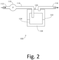
- FIG. 2 depicts the overall configuration of the decontamination apparatus 100.
- the decontamination apparatus 100 includes a pump 110 and a vapor generator unit 120. Pipes 112 and 114 are connected to the pump 110. The pipe 112 is connected to the pipe 101. The pump 110 is configured to suck air from the pipe 112 side and to supply air to the pipe 114 side.
- the vapor generator unit 120 is configured to generate only vapor containing peracetic acid, without heating a chemical solution 126 and without releasing mist.
- the vapor generator unit 120 includes a container 122, a moisture absorbing member 124, and the chemical solution 126.
- the container 122 is a sealed container that is cylindrical.
- the container 122 holds the moisture absorbing member 124 and the chemical solution 126.
- the chemical solution 126 is a medical agent in liquid form containing peracetic acid. That is, the chemical solution 126 is a peracetic acid preparation.
- the moisture absorbing member 124 is made of a porous material, for example. The moisture absorbing member 124 is immersed in the chemical solution 126.
- the moisture absorbing member 124 sucks up the chemical solution 126 inside the container 122 by capillary action. That is, the moisture absorbing member 124 becomes soaked with the chemical solution 126.
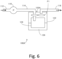
- the positions and lengths inside the sealed container that is, the container 122) of the connecting pipes (that is, the pipes 114 and 116) that connect to the sealed container.
- the positions and lengths of the connecting pipes inside the sealed container to be set to achieve this (that is, for the tips of the connecting pipes to not enter the chemical solution 126) .
- the tips of the pipes 114 and 116 prefferably be positioned so that the tip of the connecting pipe for introducing air (that is, the pipe 114) and the tip of the connecting pipe for exhausting air (that is, the pipe 116) are physically separated, so that the air flow path is long and generation of peracetic acid vapor at the moisture absorbing member 124 is promoted.
- the moisture absorbing member 124 may be formed of a sheet-like material, such as woven fabric, knitted fabric, non-woven fabric, or a film, which may be used in that state or may be formed into a pleated or corrugated shape.
- a porous material such as silica gel or zeolite, may be encapsulated in woven fabric, knitted fabric, non-woven fabric, a film, or the like.
- the decontamination apparatus 100 since the chemical solution 126 is not heated, it is possible to suppress decomposition of the peracetic acid and efficiently generate peracetic acid vapor. Additionally, according to the decontamination apparatus 100, the temperature of the chemical solution 126 containing peracetic acid is kept at a similar temperature to the temperature of the space in which the HEPA filters 210 and 220 to be decontaminated are placed, which makes it possible to suppress the risk of condensation occurring within the space.
- the moisture absorbing member 124 is contacted by air supplied from the pump 110 via the pipe 114, which promotes vaporization of the chemical solution 126 that has soaked into the moisture absorbing member 124. As a result, vapor containing peracetic acid (hereinafter, also referred to as "peracetic acid vapor”) is generated.
- the peracetic acid vapor is supplied to the inside of the safety cabinet 200 via the pipe 116. Note that the pipe 116 is connected to the pipe 102.
- the inside of the safety cabinet 200 is decontaminated by the peracetic acid vapor.
- the HEPA filters 210 and 220 are also decontaminated.
- the reason why the decontamination system 10 performs decontamination using peracetic acid vapor instead of mist containing peracetic acid is described below. In other words, the reason why vaporization (vapor) is used and not atomization (mist) will be described.
- mist will collect at the HEPA filters 210 and 220.
- the peracetic acid vapor generated by vaporization does not collect as particles at the HEPA filters 210 and 220. Accordingly, the above problems with atomization do not occur. Vaporization is adopted in the decontamination system 10 for this reason.
- the pump 110 is configured to suck air containing peracetic acid vapor from the exhaust side of the HEPA filter 210 and to supply air containing peracetic acid vapor to the air supplying side of the HEPA filter 210.
- the amount of air sucked by the pump 110 from the exhaust side of the HEPA filter 210 is larger than the amount of air supplied by the pump 110 to the air supplying side of the HEPA filter 210. This can be achieved, for example, by allowing some air in the pipe 102 to leak. Since the leaked air contains decontamination gas, it is preferable to discharge air to the outside after absorbing the decontamination gas with a chemical filter such as activated carbon. Aside from the pipe 102, leaks may be provided at other locations, like the pump on the pipe 114 and the pipe 116.
- the inside of the safety cabinet 200 is placed in a negative pressure state during decontamination. By doing so, it is possible to prevent the peracetic acid vapor from leaking to the outside of the safety cabinet 200.
- the inside of the safety cabinet 200 When the inside of the safety cabinet 200 is placed in a negative pressure state, it is preferable to prevent the negative pressure from becoming excessively high. If the negative pressure becomes too high, there is the risk of denting of the side walls of the safety cabinet 200 and other problems.
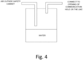
- an opening in the safety cabinet 200 To avoid excessive depressurization, it is preferable to provide an opening in the safety cabinet 200.
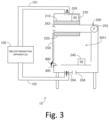
- communication holes such as the communication holes 262 and 266 may be opened, and as depicted in FIG. 3 , a gap may be provided in a lower part of the shutter 250, and a tube 300 may be placed in this gap of the shutter 250.
- Such openings pass through between the inside and outside of the safety cabinet 200 even during decontamination.
- the inner diameters of the tube 300 and the communication holes are 1 mm to 3 cm, for example.
- the gap at the lower part of the shutter 250 aside from the tube 300 is covered by the masking tape 400.
- parts of the pipes 114, 116, and 102 on the exhaust side of the pump 110 can be provided with closable openings for discharging the air that circulates inside the safety cabinet 200, the decontamination apparatus 100, and the pipes 101 and 102. If the humidity inside the safety cabinet 200 has become too high, it is possible to discharge the air circulating inside the safety cabinet 200 from the openings and to increase the amount of air introduced into the safety cabinet 200 via the tube 300 and the opened communication holes (openings) 262 and 266 to lower the humidity inside the safety cabinet 200. It is preferable for the air that is released to be discharged after the decontamination gas has been recovered by a chemical filter or the like.
- the humidity inside the safety cabinet 200 can be controlled by using the tube 300 or the openings of the opened communication holes 262 and 266. Note that as the amount of air introduced into the safety cabinet 200 through the tube 300 or the openings of the opened communication holes 262 and 266 increases, the concentration of the peracetic acid vapor will decrease. Accordingly, the amount of air introduced into the safety cabinet 200 through the tube 300 or the opened communication holes 262 and 266 should preferably be 3% or less, for example, of the amount of air circulating in the decontamination system 10.
- the fan 205 it is also preferable for the fan 205 to be stopped during decontamination. This is because when the fan 205 operates and emits heat, the temperature of the air inside the safety cabinet 200 will rise, which can cause condensation.
- FIG. 5 is a flowchart depicting an example decontamination procedure for the inside of the safety cabinet 200. Each step depicted in this flowchart is performed by an operator.
- the operator places the BIs 230 and 240 inside the safety cabinet 200 (step S100).
- the operator connects the decontamination apparatus 100 to the safety cabinet 200 using the pipes 101 and 102 (step S110).
- the operator provides openings in the safety cabinet 200 and covers gaps with the masking tape 400 (step S120).
- the operator operates the decontamination apparatus 100 to start decontamination of the inside of the safety cabinet 200 (step S130).
- step S140 The operator determines whether a predetermined period has elapsed. The operator stands by until the predetermined period elapses (NO in step S140). When the predetermined period has elapsed (YES in step S140), the operator confirms the decontamination effect based on a death state for the BIs 230 and 240 (step S150). Decontamination of the inside of the safety cabinet 200 is completed by confirming a death state for the BIs 230 and 240.
- vapor containing peracetic acid is sucked from the exhaust side of the HEPA filter 210 and the vapor is supplied to the air supplying side of the HEPA filter 210. If sucking of the peracetic acid vapor were not performed, since the specific gravity of the peracetic acid is high, the peracetic acid vapor supplied to the inside of the safety cabinet 200 would tend to accumulate at the bottom portion inside the safety cabinet 200. Were the peracetic acid vapor to accumulate at the bottom portion of the safety cabinet 200, the peracetic acid vapor would not pass through the HEPA filter 210, which may result in a situation where the HEPA filter 210 is not sufficiently decontaminated.
- peracetic acid vapor is sucked from the exhaust side of the HEPA filter 210 and peracetic acid vapor is also supplied to the air supplying side of the HEPA filter 210. Accordingly, by using the decontamination apparatus 100, the peracetic acid vapor will definitely pass through the HEPA filter 210, which makes it possible to suppress the occurrence of situations where the HEPA filter 210 is not decontaminated in spite of decontamination having been performed.
- the humidity inside the safety cabinet 200 will rise. If the temperature inside the safety cabinet 200 were to rise during decontamination, the temperature difference between the inside and the outside of the safety cabinet 200 would increase so that condensation may occur inside the safety cabinet 200.
- the temperature of the pump 110 included in the decontamination apparatus 100 rises. Accordingly, if the pump 110 were disposed inside the safety cabinet 200, the temperature inside the safety cabinet 200 would rise and condensation may occur inside the safety cabinet 200.
- the decontamination apparatus 100 is used in a state where the decontamination apparatus 100 is disposed outside the safety cabinet 200. Accordingly, with the decontamination apparatus 100, since the temperature of the pump 110 has almost no influence on the temperature inside the safety cabinet 200, it is possible to reduce the risk of condensation occurring inside the safety cabinet 200.
- the decontamination system 10 depicted in FIG. 1 was prepared.
- As the safety cabinet 200 an "MHE-181AB3" manufactured by PHC Corporation was used and installed in a location that was not directly contacted by air expelled by an air conditioner in the room.
- As the chemical solution 126 (see FIG. 2 ), "Mincare” manufactured by Cantel Medical Corp. was used.
- "HMV-091” with a bacterial count of 106 manufactured by MesaLab was used as the BIs 230 and 240.
- As the culture medium for the BIs 230 and 240 "PM/100” manufactured by MesaLab was used.
- As a thermo-hygrometer for measuring the temperature and humidity inside the safety cabinet 200 a "LR5001" temperature-humidity logger manufactured by Hioki Co., Ltd. was used.
- the decontamination apparatus 100 and the safety cabinet 200 were connected using the pipes 101 and 102 so as to suck air from the downstream side of the HEPA filter 210 and to supply air into the safety cabinet 200 from a drain portion.
- Masking of the safety cabinet 200 was performed to close the communication holes 262 and 266 and place the inside of the safety cabinet 200 in a semi-sealed state.
- the tube 300 was attached to a gap in the safety cabinet 200.
- the pump 110 was operated with a pressure gauge attached to the tube 300. The needle of the pressure gauge advanced toward negative pressure.
- a flow meter was also attached to the tube 300 to measure the flow rate. The flow rate was 5 ml/min.
- Mincare (with a peracetic acid content of 4.5%) diluted with pure water was used as the chemical solution 126.
- the dilution ratio was 10%.
- As the container 122 a cylindrical sealed container with an inner diameter of around 200 mm and a height of around 300 mm was used. The container 122 was filled with 1 L of the chemical solution 126. A cylindrical moisture absorbing member 124 was disposed around the inner circumference of the container 122.
- the BIs 230 and 240 were respectively placed above the HEPA filter 210 and inside the work area WA1. After decontamination, the BIs 230 and 240 were cultured.
- the circulating flow rate of the pump 110 was 120 L/min.
- the decontamination period was 185 minutes.
- the humidity inside the safety cabinet 200 after 3 hours was RH94%.
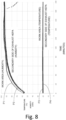
- FIG. 8 is a graph collectively showing values of the thermo-hygrometer during decontamination.
- each point P1 indicates the humidity in the work area WA1 and each point P2 indicates the humidity above the HEPA filter 210.
- Each point P3 indicates the temperature in the work area WA1, and each point P4 indicates the temperature above the HEPA filter 210. In this experiment, condensation did not occur inside the safety cabinet 200.
- the BIs 230 and 240 were cultured.
- the BIs 230 and 240 were completely dead (negative). Also, since the pump 110 was disposed outside the safety cabinet 200, no rise in temperature was observed inside the safety cabinet 200.
Landscapes
- Health & Medical Sciences (AREA)
- Epidemiology (AREA)
- Life Sciences & Earth Sciences (AREA)
- Animal Behavior & Ethology (AREA)
- General Health & Medical Sciences (AREA)
- Public Health (AREA)
- Veterinary Medicine (AREA)
- Chemical & Material Sciences (AREA)
- Chemical Kinetics & Catalysis (AREA)
- General Chemical & Material Sciences (AREA)
- Apparatus For Disinfection Or Sterilisation (AREA)
Applications Claiming Priority (2)
| Application Number | Priority Date | Filing Date | Title |
|---|---|---|---|
| JP2020167522 | 2020-10-02 | ||
| PCT/JP2021/036526 WO2022071602A1 (ja) | 2020-10-02 | 2021-10-01 | 除染装置及び除染方法 |
Publications (2)
| Publication Number | Publication Date |
|---|---|
| EP4223322A1 true EP4223322A1 (de) | 2023-08-09 |
| EP4223322A4 EP4223322A4 (de) | 2025-02-12 |
Family
ID=80951747
Family Applications (1)
| Application Number | Title | Priority Date | Filing Date |
|---|---|---|---|
| EP21875897.7A Pending EP4223322A4 (de) | 2020-10-02 | 2021-10-01 | Dekontaminationsvorrichtung und dekontaminationsverfahren |
Country Status (5)
| Country | Link |
|---|---|
| US (1) | US20230364285A1 (de) |
| EP (1) | EP4223322A4 (de) |
| JP (1) | JP7824880B2 (de) |
| TW (1) | TWI883274B (de) |
| WO (1) | WO2022071602A1 (de) |
Families Citing this family (1)
| Publication number | Priority date | Publication date | Assignee | Title |
|---|---|---|---|---|
| JP7392235B1 (ja) * | 2023-06-06 | 2023-12-06 | Sdバイオシステム株式会社 | 無菌性密閉空間内の除染装置及び当該装置を用いた除染方法 |
Family Cites Families (11)
| Publication number | Priority date | Publication date | Assignee | Title |
|---|---|---|---|---|
| US6036918A (en) * | 1993-03-17 | 2000-03-14 | Enviro Medical Systems, Inc. | Vapor sterilization |
| US6936434B2 (en) * | 2001-04-17 | 2005-08-30 | Steris Inc. | Vapor phase decontamination process biological indicator evaluator resistomer (BIER) vessel |
| JP4426851B2 (ja) * | 2002-03-28 | 2010-03-03 | バイオケル ユーケイ リミテッド | 閉じた空間を除染する方法及び装置 |
| JP2006271583A (ja) * | 2005-03-29 | 2006-10-12 | Hitachi Plant Technologies Ltd | ファンフィルタユニット及びクリーンルームの殺菌装置並びにその方法 |
| US8236240B2 (en) * | 2006-02-25 | 2012-08-07 | James Arthur Childers | Method and system for conducting vapor phase decontamination of sealable entities and their contents |
| JP4773986B2 (ja) * | 2007-01-31 | 2011-09-14 | 株式会社Ihiシバウラ | オゾンガス殺菌装置 |
| JP5559737B2 (ja) * | 2011-04-28 | 2014-07-23 | パナソニックヘルスケア株式会社 | アイソレータ |
| JP6250491B2 (ja) | 2014-07-18 | 2017-12-20 | ファーマバイオ株式会社 | 超音波除染装置 |
| AU2016268224A1 (en) * | 2015-05-27 | 2017-12-07 | Mar Cor Purification, Inc. | Low relative humidity decontamination system |
| JP6786872B2 (ja) * | 2016-05-19 | 2020-11-18 | 澁谷工業株式会社 | アイソレータシステム |
| US20200375691A1 (en) * | 2018-02-12 | 2020-12-03 | Medivators Inc. | Peracetic acid vapor sterilization system |
-
2021
- 2021-09-30 TW TW110136559A patent/TWI883274B/zh active
- 2021-10-01 JP JP2022554160A patent/JP7824880B2/ja active Active
- 2021-10-01 US US18/029,744 patent/US20230364285A1/en active Pending
- 2021-10-01 EP EP21875897.7A patent/EP4223322A4/de active Pending
- 2021-10-01 WO PCT/JP2021/036526 patent/WO2022071602A1/ja not_active Ceased
Also Published As
| Publication number | Publication date |
|---|---|
| TW202218696A (zh) | 2022-05-16 |
| JPWO2022071602A1 (de) | 2022-04-07 |
| WO2022071602A1 (ja) | 2022-04-07 |
| US20230364285A1 (en) | 2023-11-16 |
| EP4223322A4 (de) | 2025-02-12 |
| JP7824880B2 (ja) | 2026-03-05 |
| TWI883274B (zh) | 2025-05-11 |
Similar Documents
| Publication | Publication Date | Title |
|---|---|---|
| KR102413251B1 (ko) | 무균 작업 시스템 및 무균 작업 시스템을 위한 물품-반입 방법 | |
| JP5823727B2 (ja) | アイソレータ | |
| CN100482286C (zh) | 用于在无菌条件下实施操作的包含主腔体的密封空间 | |
| CN110662606A (zh) | 安全柜及其灭菌方法 | |
| JP2012231917A (ja) | アイソレータ | |
| JP2018517539A (ja) | 低相対湿度の除染システム | |
| EP4223322A1 (de) | Dekontaminationsvorrichtung und dekontaminationsverfahren | |
| JP2023165498A (ja) | 菌・ウイルス噴霧捕集装置 | |
| US20230405168A1 (en) | Decontamination method | |
| EP3950020B1 (de) | Dekontaminationsvorrichtungen und system | |
| JP2012000531A (ja) | 汚染物質を除去するhepaフィルタを装備した装置 | |
| CN115210357A (zh) | 带臭氧去污的培养器摇床和用于对培养器摇床去污的方法 | |
| CN222175328U (zh) | 一种实验室用新型通风柜 | |
| JP7245398B1 (ja) | 除染強度センサ、除染システム、除染強度の検出方法、除染強度の検出プログラム | |
| JP7392235B1 (ja) | 無菌性密閉空間内の除染装置及び当該装置を用いた除染方法 | |
| CN219481926U (zh) | 一种净化消除装置 | |
| WO2023119757A1 (ja) | 除染強度センサ、除染システム、除染強度の検出方法、除染強度の検出プログラム | |
| JP7590270B2 (ja) | アイソレータ及びその除染方法 | |
| KR20240089208A (ko) | 제염 시스템 | |
| KR20240061980A (ko) | 공기정화 성능 평가 장치 | |
| WO2023073626A1 (en) | System and method for rapid and sterile transfer of a vial into an isolator | |
| JP2025112271A (ja) | 除染機構 | |
| TWI223641B (en) | Method and apparatus for reducing toxic gas emission |
Legal Events
| Date | Code | Title | Description |
|---|---|---|---|
| STAA | Information on the status of an ep patent application or granted ep patent |
Free format text: STATUS: THE INTERNATIONAL PUBLICATION HAS BEEN MADE |
|
| PUAI | Public reference made under article 153(3) epc to a published international application that has entered the european phase |
Free format text: ORIGINAL CODE: 0009012 |
|
| STAA | Information on the status of an ep patent application or granted ep patent |
Free format text: STATUS: REQUEST FOR EXAMINATION WAS MADE |
|
| 17P | Request for examination filed |
Effective date: 20230428 |
|
| AK | Designated contracting states |
Kind code of ref document: A1 Designated state(s): AL AT BE BG CH CY CZ DE DK EE ES FI FR GB GR HR HU IE IS IT LI LT LU LV MC MK MT NL NO PL PT RO RS SE SI SK SM TR |
|
| DAV | Request for validation of the european patent (deleted) | ||
| DAX | Request for extension of the european patent (deleted) | ||
| RIC1 | Information provided on ipc code assigned before grant |
Ipc: A61L 101/36 20060101ALI20240924BHEP Ipc: A61L 101/22 20060101ALI20240924BHEP Ipc: A61L 101/20 20060101ALI20240924BHEP Ipc: A61L 2/28 20060101ALI20240924BHEP Ipc: A61L 2/20 20060101AFI20240924BHEP |
|
| RIC1 | Information provided on ipc code assigned before grant |
Ipc: A61L 101/36 20060101ALI20240930BHEP Ipc: A61L 101/22 20060101ALI20240930BHEP Ipc: A61L 101/20 20060101ALI20240930BHEP Ipc: A61L 2/28 20060101ALI20240930BHEP Ipc: A61L 2/20 20060101AFI20240930BHEP |
|
| A4 | Supplementary search report drawn up and despatched |
Effective date: 20250113 |
|
| RIC1 | Information provided on ipc code assigned before grant |
Ipc: A61L 101/36 20060101ALI20250107BHEP Ipc: A61L 101/22 20060101ALI20250107BHEP Ipc: A61L 101/20 20060101ALI20250107BHEP Ipc: A61L 2/28 20060101ALI20250107BHEP Ipc: A61L 2/20 20060101AFI20250107BHEP |
|
| STAA | Information on the status of an ep patent application or granted ep patent |
Free format text: STATUS: EXAMINATION IS IN PROGRESS |
|
| 17Q | First examination report despatched |
Effective date: 20251020 |