WO2022071602A1 - 除染装置及び除染方法 - Google Patents
除染装置及び除染方法 Download PDFInfo
- Publication number
- WO2022071602A1 WO2022071602A1 PCT/JP2021/036526 JP2021036526W WO2022071602A1 WO 2022071602 A1 WO2022071602 A1 WO 2022071602A1 JP 2021036526 W JP2021036526 W JP 2021036526W WO 2022071602 A1 WO2022071602 A1 WO 2022071602A1
- Authority
- WO
- WIPO (PCT)
- Prior art keywords
- decontamination
- safety cabinet
- steam
- air
- filter
- Prior art date
- Legal status (The legal status is an assumption and is not a legal conclusion. Google has not performed a legal analysis and makes no representation as to the accuracy of the status listed.)
- Ceased
Links
Images


Classifications
-
- A—HUMAN NECESSITIES
- A61—MEDICAL OR VETERINARY SCIENCE; HYGIENE
- A61L—METHODS OR APPARATUS FOR STERILISING MATERIALS OR OBJECTS IN GENERAL; DISINFECTION, STERILISATION OR DEODORISATION OF AIR; CHEMICAL ASPECTS OF BANDAGES, DRESSINGS, ABSORBENT PADS OR SURGICAL ARTICLES; MATERIALS FOR BANDAGES, DRESSINGS, ABSORBENT PADS OR SURGICAL ARTICLES
- A61L2/00—Disinfection or sterilisation of materials or objects, in general; Accessories therefor
- A61L2/16—Disinfection or sterilisation of materials or objects, in general; Accessories therefor using chemical substances
- A61L2/20—Gaseous substances, e.g. vapours
-
- A—HUMAN NECESSITIES
- A61—MEDICAL OR VETERINARY SCIENCE; HYGIENE
- A61L—METHODS OR APPARATUS FOR STERILISING MATERIALS OR OBJECTS IN GENERAL; DISINFECTION, STERILISATION OR DEODORISATION OF AIR; CHEMICAL ASPECTS OF BANDAGES, DRESSINGS, ABSORBENT PADS OR SURGICAL ARTICLES; MATERIALS FOR BANDAGES, DRESSINGS, ABSORBENT PADS OR SURGICAL ARTICLES
- A61L2/00—Disinfection or sterilisation of materials or objects, in general; Accessories therefor
- A61L2/02—Disinfection or sterilisation of materials or objects, in general; Accessories therefor using physical processes
- A61L2/022—Filtration
-
- A—HUMAN NECESSITIES
- A61—MEDICAL OR VETERINARY SCIENCE; HYGIENE
- A61L—METHODS OR APPARATUS FOR STERILISING MATERIALS OR OBJECTS IN GENERAL; DISINFECTION, STERILISATION OR DEODORISATION OF AIR; CHEMICAL ASPECTS OF BANDAGES, DRESSINGS, ABSORBENT PADS OR SURGICAL ARTICLES; MATERIALS FOR BANDAGES, DRESSINGS, ABSORBENT PADS OR SURGICAL ARTICLES
- A61L2/00—Disinfection or sterilisation of materials or objects, in general; Accessories therefor
- A61L2/26—Accessories
- A61L2/28—Devices for testing the effectiveness or completeness of sterilisation or disinfection, e.g. indicators which change colour
-
- A—HUMAN NECESSITIES
- A61—MEDICAL OR VETERINARY SCIENCE; HYGIENE
- A61L—METHODS OR APPARATUS FOR STERILISING MATERIALS OR OBJECTS IN GENERAL; DISINFECTION, STERILISATION OR DEODORISATION OF AIR; CHEMICAL ASPECTS OF BANDAGES, DRESSINGS, ABSORBENT PADS OR SURGICAL ARTICLES; MATERIALS FOR BANDAGES, DRESSINGS, ABSORBENT PADS OR SURGICAL ARTICLES
- A61L2101/00—Chemical composition of materials used in disinfecting, sterilising or deodorising
- A61L2101/02—Inorganic materials
- A61L2101/20—Acids
-
- A—HUMAN NECESSITIES
- A61—MEDICAL OR VETERINARY SCIENCE; HYGIENE
- A61L—METHODS OR APPARATUS FOR STERILISING MATERIALS OR OBJECTS IN GENERAL; DISINFECTION, STERILISATION OR DEODORISATION OF AIR; CHEMICAL ASPECTS OF BANDAGES, DRESSINGS, ABSORBENT PADS OR SURGICAL ARTICLES; MATERIALS FOR BANDAGES, DRESSINGS, ABSORBENT PADS OR SURGICAL ARTICLES
- A61L2101/00—Chemical composition of materials used in disinfecting, sterilising or deodorising
- A61L2101/32—Organic compounds
- A61L2101/36—Carboxylic acids or derivatives thereof
-
- A—HUMAN NECESSITIES
- A61—MEDICAL OR VETERINARY SCIENCE; HYGIENE
- A61L—METHODS OR APPARATUS FOR STERILISING MATERIALS OR OBJECTS IN GENERAL; DISINFECTION, STERILISATION OR DEODORISATION OF AIR; CHEMICAL ASPECTS OF BANDAGES, DRESSINGS, ABSORBENT PADS OR SURGICAL ARTICLES; MATERIALS FOR BANDAGES, DRESSINGS, ABSORBENT PADS OR SURGICAL ARTICLES
- A61L2202/00—Aspects relating to methods or apparatus for disinfecting or sterilising materials or objects
- A61L2202/10—Apparatus features
- A61L2202/11—Apparatus for generating biocidal substances, e.g. vaporisers, UV lamps
-
- A—HUMAN NECESSITIES
- A61—MEDICAL OR VETERINARY SCIENCE; HYGIENE
- A61L—METHODS OR APPARATUS FOR STERILISING MATERIALS OR OBJECTS IN GENERAL; DISINFECTION, STERILISATION OR DEODORISATION OF AIR; CHEMICAL ASPECTS OF BANDAGES, DRESSINGS, ABSORBENT PADS OR SURGICAL ARTICLES; MATERIALS FOR BANDAGES, DRESSINGS, ABSORBENT PADS OR SURGICAL ARTICLES
- A61L2202/00—Aspects relating to methods or apparatus for disinfecting or sterilising materials or objects
- A61L2202/10—Apparatus features
- A61L2202/15—Biocide distribution means, e.g. nozzles, pumps, manifolds, fans, baffles, sprayers
Definitions
- the present invention relates to a decontamination device and a decontamination method.
- Patent Document 1 discloses a decontamination device configured to decontaminate the inside of a biosafety cabinet.
- this decontamination device the inside of the biosafety cabinet is decontaminated by using a mist containing peracetic acid (see Patent Document 1).
- a particle removal filter HEPA (High Efficiency Particulate Air) filter, etc.
- decontamination targets include safety cabinets, incubators, isolators and automatic incubators.
- the decontamination of the particle removing filter is performed through the decontamination of the inside of the decontamination target.
- the particle removal filter is decontaminated with a mist containing peracetic acid as in the decontamination device disclosed in Patent Document 1
- the mist quickly becomes steam.
- the relative humidity exceeds 80% the evaporation rate of the mist decreases, and the mist cannot evaporate completely and floats as the mist.
- the mist is collected by the particle removing filter.
- the pressure loss may increase.
- the present inventors considered decontaminating the particle removal filter with vapor containing peracetic acid instead of mist containing peracetic acid.
- the specific gravity of peracetic acid is large, the steam supplied to the inside of the decontamination target tends to accumulate at the bottom inside the decontamination target.
- the particle removing filter is often arranged near the ceiling. In such a case, even if steam containing peracetic acid is supplied to the inside of the decontamination target, the vapor does not pass through the particle removal filter, so that the particle removal filter may not be sufficiently decontaminated.
- the present invention has been made to solve such a problem, and an object thereof is to suppress the occurrence of a situation in which the particle removing filter is not decontaminated even though decontamination is performed. It is to provide a possible decontamination apparatus and decontamination method.
- this decontamination device In this decontamination device, steam containing peracetic acid is sucked from the exhaust side of the particle removing filter, and the steam is supplied to the air supply side of the particle removing filter. Therefore, according to this decontamination device, the vapor containing peracetic acid surely passes through the particle removing filter, so that the particle removing filter is not decontaminated even though the decontamination is performed. The occurrence can be suppressed.
- the decontamination apparatus is used in a state of being arranged outside the decontamination target. Therefore, according to this decontamination device, since the temperature of the pump has almost no effect on the temperature inside the decontamination target, it is possible to reduce the possibility of dew condensation inside the decontamination target.
- the amount of air sucked by the pump from the exhaust side of the particle removing filter may be larger than the amount of air supplied by the pump to the air supply side of the particle removing filter.
- the inside of the decontamination target becomes negative pressure. Therefore, according to this decontamination device, the steam supplied to the inside of the decontamination target can be prevented from leaking to the outside of the decontamination target.
- the decontamination method is a method of decontaminating at least one of a microorganism and a virus by using the above-mentioned decontamination device.
- This decontamination method includes a step of arranging a BI (Biological Indicator) on the exhaust side of the particle removing filter and a step of confirming the decontamination effect based on the death status of BI after decontamination.
- BI Bio Indicator
- the decontamination effect of the particle removing filter can be confirmed based on the death status of BI.
- the decontamination method is a method of decontaminating at least one of a microorganism and a virus by using the above-mentioned decontamination device.
- a gap may be formed to communicate the inside and the outside of the decontamination target.
- This decontamination method includes a step of curing the gap when the gap is formed in the decontamination target, sucking the vapor from the exhaust side of the particle removing filter, and moving to the air supply side of the particle removing filter. It includes a step of circulating the steam by supplying the steam.
- the inside of the decontamination target can be in a negative pressure state during decontamination.
- the steam supplied to the inside of the decontamination target can be prevented from leaking to the outside of the decontamination target.
- the present invention it is possible to provide a decontamination apparatus and a decontamination method capable of suppressing the occurrence of a situation in which the particle removing filter is not decontaminated despite decontamination.
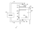
- FIG. 1 is a diagram showing a schematic configuration of a decontamination system 10 including a decontamination device 100 according to the present embodiment.
- the decontamination system 10 includes a decontamination device 100 and a safety cabinet 200.
- the decontamination device 100 is connected to the safety cabinet 200 via the pipes 101 and 102.
- the decontamination device 100 decontaminates, for example, at least one of the microorganisms and viruses present inside the safety cabinet 200.
- the decontamination device 100 is arranged outside the safety cabinet 200 to be decontaminated.
- the safety cabinet 200 is a box-shaped experimental facility for suppressing biohazard.
- the experimenter inserts his hand into the work area WA1 and conducts an experiment using, for example, a biological material.
- the safety cabinet 200 includes a fan 205, HEPA (High Efficiency Particulate Air) filters 210 and 220, and a shutter 250.
- the fan 205 operates to generate an air flow, and the clean air is discharged to the outside through the HEPA filter 210, and the clean air is supplied to the work area WA1 through the HEPA filter 220.
- the shutter 250 is configured to be openable and closable.
- the safety cabinet 200 is formed with, for example, communication holes 262,264,266,268.
- the communication hole may be installed exclusively for decontamination, or for example, a drain portion, a vacuum, and a DOP sampling port provided in a general safety cabinet may be used as the communication hole.
- Each of the communication holes 262,264,266,268 can be opened and closed.
- the decontamination device 100 is connected to the communication hole 264 via the pipe 102, and the decontamination device 100 is connected to the communication hole 268 via the pipe 101. That is, the decontamination device 100 is connected to the communication hole 268 in the ceiling of the safety cabinet 200 and the communication hole 264 in the bottom of the safety cabinet 200.
- the communication holes connecting the pipes 102 may be one or two or more.
- the shutter 250 is closed. Even when the shutter 250 is closed, the inside and the outside of the safety cabinet 200 may not be completely cut off, and in such a case, a slight gap is formed. During decontamination, the gap is cured by the curing tape 400 in order to prevent the decontamination gas from leaking, depending on the degree of the decontamination gas leak. Further, it is preferable that each of the communication holes 262 and 266 is closed.
- a BI (Biological Indicator) 230 is arranged in the space above the HEPA filter 210. Further, BI 240 is arranged in the work area WA1. After the completion of decontamination, BI230 and 240 are cultured, and the decontamination effect is confirmed based on the death status of BI230 and 240.
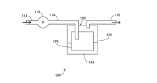
- FIG. 2 is a diagram showing a schematic configuration of the decontamination device 100.
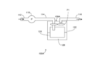
- the decontamination device 100 includes a pump 110 and a steam generator 120. Pipes 112 and 114 are connected to the pump 110.
- the tube 112 is connected to the tube 101.
- the pump 110 is configured to suck air from the pipe 112 side and supply air to the pipe 114 side.
- the steam generating unit 120 is configured to generate only steam containing peracetic acid without heating the chemical solution 126 and without releasing mist.
- the vapor generating unit 120 includes a container 122, a moisture absorbing member 124, and a chemical solution 126.
- the container 122 is, for example, a cylindrical closed container.
- the container 122 contains the hygroscopic member 124 and the chemical solution 126.
- the chemical solution 126 is a liquid drug containing peracetic acid. That is, the drug solution 126 is a peracetic acid preparation.
- the moisture absorbing member 124 is made of, for example, a porous material. The moisture absorbing member 124 is immersed in the chemical solution 126.
- the moisture absorbing member 124 sucks up the chemical solution 126 in the container 122 by the capillary phenomenon. That is, the hygroscopic member 124 is impregnated with the chemical solution 126.
- the position and length of the communication pipes (tubes 114, 116) communicating with the closed container (container 122) in the closed container are not particularly limited. However, since it is preferable that the communication pipe enters the chemical solution 126 and the chemical solution 126 does not foam, the position and length of the communication pipe in the closed container can realize such a thing (the tip of the communication pipe is inside the chemical solution 126). It is preferable that it does not enter.
- the tip of the communication pipe (pipe 114) for introducing air and the tip of the communication pipe (pipe 116) for exhausting air are separated from each other, the air flow path is long, and the peracetic acid vapor of the moisture absorbing member 124 is generated. It is preferable that the tips of the tubes 114 and 116 are present at the positions to be promoted.
- the structure and members of the moisture absorbing member 124 are not particularly limited as long as they are moistened with the chemical solution 126 and the chemical solution 126 can be efficiently gasified (vaporized) by ventilation.
- the moisture absorbing member 124 may be a sheet-like material such as a woven fabric, a knitted fabric, a non-woven fabric, or a film as it is, or may be formed by processing it into a fold-folded shape or a corrugated shape.
- a porous material such as silica gel or zeolite may be encapsulated in a woven fabric, a knitted fabric, a non-woven fabric, a film or the like.
- the decontamination device 100 since the chemical solution 126 is not heated, it is possible to suppress the decomposition of peracetic acid and efficiently generate peracetic acid vapor. Further, according to the decontamination apparatus 100, the temperature of the chemical solution 126 containing peracetic acid is maintained at the same level as the temperature in the space in which the HEPA filters 210 and 220 to be decontaminated are arranged. The possibility of dew condensation can be suppressed.
- Air is supplied from the pump 110 via the pipe 114, and the vaporization of the chemical solution 126 that has soaked into the moisture absorbing member 124 is promoted. As a result, vapor containing peracetic acid (hereinafter, also referred to as "peracetic acid vapor") is generated.
- the peracetic acid vapor is supplied to the inside of the safety cabinet 200 via the pipe 116.
- the pipe 116 is connected to the pipe 102.
- the inside of the safety cabinet 200 is decontaminated by the peracetic acid steam.
- the HEPA filters 210 and 220 are also decontaminated through the decontamination in the safety cabinet 200.
- decontamination is performed by the peracetic acid vapor instead of the mist containing peracetic acid in the decontamination system 10 will be described below. That is, the reason why the vaporization type (steam) is used instead of the atomization type (mist) will be described.
- the HEPA filters 210 and 220 are decontaminated with a mist containing peracetic acid, the mist is collected by the HEPA filters 210 and 220.
- the pressure loss may be improved by getting wet with the collected mist, or the deterioration may be accelerated by the decontaminating agent.
- the peracetic acid vapor generated by the vaporization method is not collected as particles by the HEPA filters 210 and 220. Therefore, the problem in the atomization formula does not occur. For this reason, the vaporization type is adopted in the decontamination system 10.
- the pump 110 is configured to suck air containing peracetic acid vapor from the exhaust side of the HEPA filter 210 and supply air containing peracetic acid vapor to the air supply side of the HEPA filter 210.
- the amount of air sucked by the pump 110 from the exhaust side of the HEPA filter 210 is larger than the amount of air supplied by the pump 110 to the air supply side of the HEPA filter 210. This is achieved, for example, by leaking some air in the tube 102. Since the leaked air contains a decontamination gas, it is preferable to discharge the decontamination gas to the outside after adsorbing it with a chemical filter such as activated carbon.
- the leak location may be not only the pipe 102 but also the pump of the pipe 114 or the pipe 116.
- the inside of the safety cabinet 200 is in a negative pressure state during decontamination. As a result, it is possible to prevent the peracetic acid vapor from leaking to the outside of the safety cabinet 200.
- the inside of the safety cabinet 200 When the inside of the safety cabinet 200 is in a negative pressure state, it is preferable not to make the negative pressure too high. If the negative pressure becomes too high, a dent on the side wall of the safety cabinet 200 may be generated.
- the communication holes such as the communication holes 262 and 266 may be opened, or as shown in FIG. 3, the gap may be the lower part of the shutter 250, and the tube 300 is arranged in the gap of the shutter 250. You may. Even during decontamination, the openings allow the inside and outside of the safety cabinet 200 to communicate with each other.
- the inner diameter of each of the tube 300 and the communication hole is, for example, 1 mm to 3 cm. Further, during decontamination, the gaps under the shutter 250 except for the tube 300 are cured by the curing tape 400.
- an opening is provided in the safety cabinet 200 at the time of decontamination, and air is taken into the inside of the safety cabinet 200 through the opening, so that the inside of the safety cabinet 200 does not become too negative pressure.
- a part of the pipes 114, 116, 102 on the exhaust side of the pump 110 is provided with an openable / closable opening for discharging air circulating inside the safety cabinet 200, the decontamination device 100, and the pipes 101, 102. Can be done. If the humidity inside the safety cabinet 200 becomes too high, the air circulating inside the safety cabinet 200 is discharged from the opening, and the safety cabinet 200 is discharged through the tube 300 and the open communication holes 262 and 266 (openings). It is possible to increase the amount of air taken into the inside of the safety cabinet 200 and reduce the humidity in the safety cabinet 200. It is preferable that the released air is discharged after the decontamination gas is recovered by a chemical filter or the like.
- the humid air can be used in the tube 300 or the open communication hole 2622. Since it is introduced inside the safety cabinet 200 via 266, the humidity inside the safety cabinet 200 can be increased. This is effective when the humidity of the air outside the safety cabinet 200 is low and the humidity inside the safety cabinet 200 is too low. That is, the humidity in the safety cabinet 200 can be controlled by using the opening of the tube 300 or the open communication holes 262,266. As the amount of air introduced into the safety cabinet 200 through the opening of the tube 300 or the open communication holes 262,266 increases, the concentration of the peracetic acid vapor decreases. Therefore, the amount of air introduced into the safety cabinet 200 through the tube 300 or the open communication holes 262,266 is, for example, 3% or less of the amount of air circulating in the decontamination system 10. Is preferable.
- the fan 205 is stopped during decontamination. This is because when the fan 205 operates and generates heat, the temperature of the air in the safety cabinet 200 rises, which causes dew condensation.
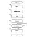
- FIG. 5 is a flowchart showing an example of the decontamination procedure in the safety cabinet 200. Each step shown in this flowchart is performed by an operator.
- the operator arranges the BI 230 and 240 in the safety cabinet 200 (step S100).
- the operator connects the decontamination device 100 to the safety cabinet 200 by using the pipes 101 and 102 (step S110).
- the operator provides an opening in the safety cabinet 200 as needed, and cures the gap with the curing tape 400 (step S120).
- the operator activates the decontamination device 100 to start decontamination in the safety cabinet 200 (step S130).
- step S140 The worker determines whether or not the predetermined time has elapsed.
- the worker waits until a predetermined time elapses (NO in step S140).
- the operator confirms the decontamination effect based on the dead state of BI 230 and 240 (step S150). Decontamination in the safety cabinet 200 is completed by confirming the death of BI 230 and 240.
- the peracetic acid vapor is sucked from the exhaust side of the HEPA filter 210, and the peracetic acid vapor is supplied to the air supply side of the HEPA filter 210. Therefore, according to the decontamination apparatus 100, the peracetic acid vapor surely passes through the HEPA filter 210, so that the occurrence of a situation in which the HEPA filter 210 is not decontaminated even though the decontamination is performed is suppressed. be able to.
- the humidity inside the safety cabinet 200 rises because the aqueous solution containing peracetic acid is vaporized. If the temperature inside the safety cabinet 200 rises during decontamination, the temperature difference between the inside and the outside of the safety cabinet 200 becomes large, and dew condensation may occur inside the safety cabinet 200.
- the temperature of the pump 110 included in the decontamination device 100 rises. Therefore, if the pump 110 is arranged inside the safety cabinet 200, the temperature inside the safety cabinet 200 rises, and dew condensation may occur inside the safety cabinet 200.
- the decontamination device 100 is used in a state of being arranged outside the safety cabinet 200. Therefore, according to the decontamination device 100, the temperature of the pump 110 has almost no effect on the temperature inside the safety cabinet 200, so that the possibility of dew condensation inside the safety cabinet 200 can be reduced.
- the particle removing filters arranged in the safety cabinet 200 are HEPA filters 210 and 220.
- the particle removing filter arranged in the safety cabinet 200 is not limited to this.
- the particle removal filter to be decontaminated may be, for example, a medium performance filter or a ULPA filter.
- the decontamination target was the safety cabinet 200.
- the decontamination target is not limited to this.
- the decontamination target may be any container as long as it can accommodate the particle removing filter inside.
- the decontamination target may be hermetically sealed or may be in a semi-enclosed state.
- the semi-sealed state is a state in which the seal is close to the seal but cannot be completely sealed.
- the air between the inside and the outside of the safety cabinet 200 is blocked at a certain level, and the concentration of the peracetic acid vapor does not decrease extremely due to the leakage of the peracetic acid vapor.
- the decontamination target may be an isolator device, an incubator, a centrifuge, a pass box, a storage, an air conditioner, a clean bench, a duct, or the like.
- the air flow is in the order of the safety cabinet 200, the pump 110, the steam generator 120, and the safety cabinet 200, but the order of air flow is not limited to this.
- air may flow in the order of the safety cabinet 200, the steam generator 120, the pump 110, and the safety cabinet 200.
- the structure of the steam generating unit 120 may be a structure that generates peracetic acid vapor without generating mist.
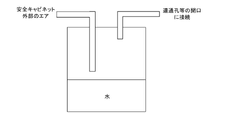
- a stirring fan F1 for promoting steaming may be installed in the steam generating unit 120A, and if the steaming is sufficient, the porous body 124 may be omitted. ..
- the structure of the steam generating unit 120 may be as shown in FIG. 7. That is, in the vapor generating section 120B, the moisture absorbing member 124B sucks up the chemical solution 126B by the capillary phenomenon.
- the peracetic acid steam (gas) is flowed to the pipe 116B side by the air introduced into the steam generator 120B through the pipe 114B.
- the peracetic acid vapor is introduced into the safety cabinet 200 via the tube 116B.
- the pump 110 may be capable of sucking and exhausting air and having the ability to circulate air for the present invention, eg, centrifugal blowers, axial blowers, mixed flow blowers, cross flow blowers, diaphragm pumps, pistons.
- air for the present invention eg, centrifugal blowers, axial blowers, mixed flow blowers, cross flow blowers, diaphragm pumps, pistons.
- the decontamination system 10 shown in FIG. 1 was prepared.
- MHE-181AB3 manufactured by PHC Corporation was used and installed in a place where the wind of the air conditioner in the room did not directly hit.
- chemical solution 126 (FIG. 2), Mincare manufactured by Cantel Co., Ltd. was used.
- BI 230 and 240 HMV-091 bacterial count 106 manufactured by MesaLab was used.
- culture medium of BI230 and 240 PM / 100 manufactured by MesaLab was used.
- a thermo-hygrometer for measuring the temperature and humidity in the safety cabinet 200 a temperature-humidity logger LR5001 manufactured by Hioki Co., Ltd. was used.
- the decontamination device 100 and the safety cabinet 200 were connected using pipes 101 and 102 so as to suck air from the downstream side of the HEPA filter 210 and supply air into the safety cabinet 200 from the drain portion.
- the safety cabinet 200 was cured, the communication holes 262 and 266 were closed, and the inside of the safety cabinet 200 was placed in a semi-sealed state.
- a tube 300 was attached to the gap of the safety cabinet 200.
- the pump 110 was operated with the pressure gauge attached to the tube 300.
- the needle of the pressure gauge advanced toward the negative pressure.
- a flow meter was attached to the tube 300 to measure the flow rate. The flow rate was 5 ml / min.
- Mincare peracetic acid content 4.5%) diluted with pure water was used as the chemical solution 126.
- the dilution ratio was 10%.
- As the container 122 a cylindrical closed container having an inner diameter of about 200 mm and a height of about 300 mm was used. The container 122 was filled with 1 L of the chemical solution 126. Further, the cylindrical moisture absorbing member 124 was arranged along the inner circumference of the container 122.
- BI230 and 240 were arranged above the HEPA filter 210 and in the work area WA1, respectively. After decontamination, BI230 and 240 were cultured.
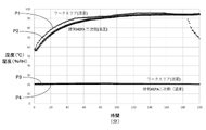
- FIG. 8 is a diagram summarizing the values of the thermo-hygrometer at the time of decontamination.
- each point P1 indicates the humidity in the work area WA1 and each point P2 indicates the humidity above the HEPA filter 210.
- Each point P3 indicates the temperature in the work area WA1, and each point P4 indicates the temperature above the HEPA filter 210. In this experiment, no dew condensation occurred in the safety cabinet 200.
- BI230 and 240 were cultured. BI230 and 240 were all dead (negative). Further, since the pump 110 was arranged outside the safety cabinet 200, no temperature rise was observed inside the safety cabinet 200.
Landscapes
- Health & Medical Sciences (AREA)
- Epidemiology (AREA)
- Life Sciences & Earth Sciences (AREA)
- Animal Behavior & Ethology (AREA)
- General Health & Medical Sciences (AREA)
- Public Health (AREA)
- Veterinary Medicine (AREA)
- Chemical & Material Sciences (AREA)
- Chemical Kinetics & Catalysis (AREA)
- General Chemical & Material Sciences (AREA)
- Apparatus For Disinfection Or Sterilisation (AREA)
Priority Applications (3)
| Application Number | Priority Date | Filing Date | Title |
|---|---|---|---|
| US18/029,744 US20230364285A1 (en) | 2020-10-02 | 2021-10-01 | Decontamination apparatus and decontamination method |
| EP21875897.7A EP4223322A4 (de) | 2020-10-02 | 2021-10-01 | Dekontaminationsvorrichtung und dekontaminationsverfahren |
| JP2022554160A JP7824880B2 (ja) | 2020-10-02 | 2021-10-01 | 除染装置及び除染方法 |
Applications Claiming Priority (2)
| Application Number | Priority Date | Filing Date | Title |
|---|---|---|---|
| JP2020-167522 | 2020-10-02 | ||
| JP2020167522 | 2020-10-02 |
Publications (1)
| Publication Number | Publication Date |
|---|---|
| WO2022071602A1 true WO2022071602A1 (ja) | 2022-04-07 |
Family
ID=80951747
Family Applications (1)
| Application Number | Title | Priority Date | Filing Date |
|---|---|---|---|
| PCT/JP2021/036526 Ceased WO2022071602A1 (ja) | 2020-10-02 | 2021-10-01 | 除染装置及び除染方法 |
Country Status (5)
| Country | Link |
|---|---|
| US (1) | US20230364285A1 (de) |
| EP (1) | EP4223322A4 (de) |
| JP (1) | JP7824880B2 (de) |
| TW (1) | TWI883274B (de) |
| WO (1) | WO2022071602A1 (de) |
Cited By (1)
| Publication number | Priority date | Publication date | Assignee | Title |
|---|---|---|---|---|
| JP7392235B1 (ja) * | 2023-06-06 | 2023-12-06 | Sdバイオシステム株式会社 | 無菌性密閉空間内の除染装置及び当該装置を用いた除染方法 |
Citations (6)
| Publication number | Priority date | Publication date | Assignee | Title |
|---|---|---|---|---|
| US20020160440A1 (en) * | 2001-04-17 | 2002-10-31 | Mcdonnell Gerald E. | Vapor phase decontamination process biological indicator evaluator resistomer (BIER) vessel |
| JP2006271583A (ja) * | 2005-03-29 | 2006-10-12 | Hitachi Plant Technologies Ltd | ファンフィルタユニット及びクリーンルームの殺菌装置並びにその方法 |
| JP2008188043A (ja) * | 2007-01-31 | 2008-08-21 | Ihi Shibaura Machinery Corp | 殺菌ガス浸透装置 |
| JP2017205080A (ja) * | 2016-05-19 | 2017-11-24 | 澁谷工業株式会社 | アイソレータシステム |
| JP6250491B2 (ja) | 2014-07-18 | 2017-12-20 | ファーマバイオ株式会社 | 超音波除染装置 |
| JP2018517539A (ja) * | 2015-05-27 | 2018-07-05 | マー コア ピュリフィケーション,インコーポレイテッド | 低相対湿度の除染システム |
Family Cites Families (5)
| Publication number | Priority date | Publication date | Assignee | Title |
|---|---|---|---|---|
| US6036918A (en) * | 1993-03-17 | 2000-03-14 | Enviro Medical Systems, Inc. | Vapor sterilization |
| JP4426851B2 (ja) * | 2002-03-28 | 2010-03-03 | バイオケル ユーケイ リミテッド | 閉じた空間を除染する方法及び装置 |
| US8236240B2 (en) * | 2006-02-25 | 2012-08-07 | James Arthur Childers | Method and system for conducting vapor phase decontamination of sealable entities and their contents |
| JP5559737B2 (ja) * | 2011-04-28 | 2014-07-23 | パナソニックヘルスケア株式会社 | アイソレータ |
| US20200375691A1 (en) * | 2018-02-12 | 2020-12-03 | Medivators Inc. | Peracetic acid vapor sterilization system |
-
2021
- 2021-09-30 TW TW110136559A patent/TWI883274B/zh active
- 2021-10-01 JP JP2022554160A patent/JP7824880B2/ja active Active
- 2021-10-01 US US18/029,744 patent/US20230364285A1/en active Pending
- 2021-10-01 EP EP21875897.7A patent/EP4223322A4/de active Pending
- 2021-10-01 WO PCT/JP2021/036526 patent/WO2022071602A1/ja not_active Ceased
Patent Citations (6)
| Publication number | Priority date | Publication date | Assignee | Title |
|---|---|---|---|---|
| US20020160440A1 (en) * | 2001-04-17 | 2002-10-31 | Mcdonnell Gerald E. | Vapor phase decontamination process biological indicator evaluator resistomer (BIER) vessel |
| JP2006271583A (ja) * | 2005-03-29 | 2006-10-12 | Hitachi Plant Technologies Ltd | ファンフィルタユニット及びクリーンルームの殺菌装置並びにその方法 |
| JP2008188043A (ja) * | 2007-01-31 | 2008-08-21 | Ihi Shibaura Machinery Corp | 殺菌ガス浸透装置 |
| JP6250491B2 (ja) | 2014-07-18 | 2017-12-20 | ファーマバイオ株式会社 | 超音波除染装置 |
| JP2018517539A (ja) * | 2015-05-27 | 2018-07-05 | マー コア ピュリフィケーション,インコーポレイテッド | 低相対湿度の除染システム |
| JP2017205080A (ja) * | 2016-05-19 | 2017-11-24 | 澁谷工業株式会社 | アイソレータシステム |
Non-Patent Citations (1)
| Title |
|---|
| See also references of EP4223322A4 |
Cited By (2)
| Publication number | Priority date | Publication date | Assignee | Title |
|---|---|---|---|---|
| JP7392235B1 (ja) * | 2023-06-06 | 2023-12-06 | Sdバイオシステム株式会社 | 無菌性密閉空間内の除染装置及び当該装置を用いた除染方法 |
| WO2024253121A1 (ja) * | 2023-06-06 | 2024-12-12 | Sdバイオシステム株式会社 | 無菌性密閉空間内の除染装置及び当該装置を用いた除染方法 |
Also Published As
| Publication number | Publication date |
|---|---|
| TW202218696A (zh) | 2022-05-16 |
| JPWO2022071602A1 (de) | 2022-04-07 |
| EP4223322A1 (de) | 2023-08-09 |
| US20230364285A1 (en) | 2023-11-16 |
| EP4223322A4 (de) | 2025-02-12 |
| JP7824880B2 (ja) | 2026-03-05 |
| TWI883274B (zh) | 2025-05-11 |
Similar Documents
| Publication | Publication Date | Title |
|---|---|---|
| CN100482286C (zh) | 用于在无菌条件下实施操作的包含主腔体的密封空间 | |
| JP5823727B2 (ja) | アイソレータ | |
| JP6411286B2 (ja) | 過酸化水素ガス除去装置 | |
| JP5559737B2 (ja) | アイソレータ | |
| EA020601B1 (ru) | Способ дезинфекции или стерилизации изделия | |
| JP6338521B2 (ja) | アイソレータ | |
| CN110662606A (zh) | 安全柜及其灭菌方法 | |
| JP7824880B2 (ja) | 除染装置及び除染方法 | |
| JP5824112B2 (ja) | アイソレータ、アイソレータの制御方法 | |
| US9943620B2 (en) | Chlorine dioxide decontamination system and methods | |
| JP7087211B1 (ja) | 除染方法 | |
| JP7525992B2 (ja) | 除染装置 | |
| CN102639344B (zh) | 用于维护车辆中的冷却系统的方法和装置 | |
| EP3950020B1 (de) | Dekontaminationsvorrichtungen und system | |
| JP2018114202A (ja) | 除染装置及びそれを備える空気清浄システム | |
| JP2023165498A (ja) | 菌・ウイルス噴霧捕集装置 | |
| CN115210357A (zh) | 带臭氧去污的培养器摇床和用于对培养器摇床去污的方法 | |
| JP2011041524A (ja) | 微生物除去評価装置および微生物除去評価方法 | |
| JP7245398B1 (ja) | 除染強度センサ、除染システム、除染強度の検出方法、除染強度の検出プログラム | |
| WO2023119757A1 (ja) | 除染強度センサ、除染システム、除染強度の検出方法、除染強度の検出プログラム | |
| JP7392235B1 (ja) | 無菌性密閉空間内の除染装置及び当該装置を用いた除染方法 | |
| JP7668999B2 (ja) | 二酸化塩素ガスによる除染方法及び除染装置 | |
| US20220325222A1 (en) | Laboratory device with low particle emission | |
| JP2025139159A (ja) | 過酸化水素ガス除染装置 | |
| KR20240061980A (ko) | 공기정화 성능 평가 장치 |
Legal Events
| Date | Code | Title | Description |
|---|---|---|---|
| 121 | Ep: the epo has been informed by wipo that ep was designated in this application |
Ref document number: 21875897 Country of ref document: EP Kind code of ref document: A1 |
|
| ENP | Entry into the national phase |
Ref document number: 2022554160 Country of ref document: JP Kind code of ref document: A |
|
| NENP | Non-entry into the national phase |
Ref country code: DE |
|
| ENP | Entry into the national phase |
Ref document number: 2021875897 Country of ref document: EP Effective date: 20230502 |