EP4225623B1 - Système de guidage de véhicule et procédé de fonctionnement d'une fonction de conduite en présence d'une contradiction avec des données cartographiques - Google Patents
Système de guidage de véhicule et procédé de fonctionnement d'une fonction de conduite en présence d'une contradiction avec des données cartographiques Download PDFInfo
- Publication number
- EP4225623B1 EP4225623B1 EP21790414.3A EP21790414A EP4225623B1 EP 4225623 B1 EP4225623 B1 EP 4225623B1 EP 21790414 A EP21790414 A EP 21790414A EP 4225623 B1 EP4225623 B1 EP 4225623B1
- Authority
- EP
- European Patent Office
- Prior art keywords
- vehicle
- signaling unit
- driving function
- basis
- driving
- Prior art date
- Legal status (The legal status is an assumption and is not a legal conclusion. Google has not performed a legal analysis and makes no representation as to the accuracy of the status listed.)
- Active
Links
Images



Classifications
-
- B—PERFORMING OPERATIONS; TRANSPORTING
- B60—VEHICLES IN GENERAL
- B60W—CONJOINT CONTROL OF VEHICLE SUB-UNITS OF DIFFERENT TYPE OR DIFFERENT FUNCTION; CONTROL SYSTEMS SPECIALLY ADAPTED FOR HYBRID VEHICLES; ROAD VEHICLE DRIVE CONTROL SYSTEMS FOR PURPOSES NOT RELATED TO THE CONTROL OF A PARTICULAR SUB-UNIT
- B60W50/00—Details of control systems for road vehicle drive control not related to the control of a particular sub-unit, e.g. process diagnostic or vehicle driver interfaces
- B60W50/08—Interaction between the driver and the control system
- B60W50/14—Means for informing the driver, warning the driver or prompting a driver intervention
- B60W50/16—Tactile feedback to the driver, e.g. vibration or force feedback to the driver on the steering wheel or the accelerator pedal
-
- B—PERFORMING OPERATIONS; TRANSPORTING
- B60—VEHICLES IN GENERAL
- B60W—CONJOINT CONTROL OF VEHICLE SUB-UNITS OF DIFFERENT TYPE OR DIFFERENT FUNCTION; CONTROL SYSTEMS SPECIALLY ADAPTED FOR HYBRID VEHICLES; ROAD VEHICLE DRIVE CONTROL SYSTEMS FOR PURPOSES NOT RELATED TO THE CONTROL OF A PARTICULAR SUB-UNIT
- B60W30/00—Purposes of road vehicle drive control systems not related to the control of a particular sub-unit, e.g. of systems using conjoint control of vehicle sub-units
- B60W30/14—Adaptive cruise control
-
- B—PERFORMING OPERATIONS; TRANSPORTING
- B60—VEHICLES IN GENERAL
- B60W—CONJOINT CONTROL OF VEHICLE SUB-UNITS OF DIFFERENT TYPE OR DIFFERENT FUNCTION; CONTROL SYSTEMS SPECIALLY ADAPTED FOR HYBRID VEHICLES; ROAD VEHICLE DRIVE CONTROL SYSTEMS FOR PURPOSES NOT RELATED TO THE CONTROL OF A PARTICULAR SUB-UNIT
- B60W30/00—Purposes of road vehicle drive control systems not related to the control of a particular sub-unit, e.g. of systems using conjoint control of vehicle sub-units
- B60W30/14—Adaptive cruise control
- B60W30/143—Speed control
-
- B—PERFORMING OPERATIONS; TRANSPORTING
- B60—VEHICLES IN GENERAL
- B60W—CONJOINT CONTROL OF VEHICLE SUB-UNITS OF DIFFERENT TYPE OR DIFFERENT FUNCTION; CONTROL SYSTEMS SPECIALLY ADAPTED FOR HYBRID VEHICLES; ROAD VEHICLE DRIVE CONTROL SYSTEMS FOR PURPOSES NOT RELATED TO THE CONTROL OF A PARTICULAR SUB-UNIT
- B60W30/00—Purposes of road vehicle drive control systems not related to the control of a particular sub-unit, e.g. of systems using conjoint control of vehicle sub-units
- B60W30/14—Adaptive cruise control
- B60W30/16—Control of distance between vehicles, e.g. keeping a distance to preceding vehicle
-
- B—PERFORMING OPERATIONS; TRANSPORTING
- B60—VEHICLES IN GENERAL
- B60W—CONJOINT CONTROL OF VEHICLE SUB-UNITS OF DIFFERENT TYPE OR DIFFERENT FUNCTION; CONTROL SYSTEMS SPECIALLY ADAPTED FOR HYBRID VEHICLES; ROAD VEHICLE DRIVE CONTROL SYSTEMS FOR PURPOSES NOT RELATED TO THE CONTROL OF A PARTICULAR SUB-UNIT
- B60W30/00—Purposes of road vehicle drive control systems not related to the control of a particular sub-unit, e.g. of systems using conjoint control of vehicle sub-units
- B60W30/18—Propelling the vehicle
- B60W30/18009—Propelling the vehicle related to particular drive situations
- B60W30/181—Preparing for stopping
-
- B—PERFORMING OPERATIONS; TRANSPORTING
- B60—VEHICLES IN GENERAL
- B60W—CONJOINT CONTROL OF VEHICLE SUB-UNITS OF DIFFERENT TYPE OR DIFFERENT FUNCTION; CONTROL SYSTEMS SPECIALLY ADAPTED FOR HYBRID VEHICLES; ROAD VEHICLE DRIVE CONTROL SYSTEMS FOR PURPOSES NOT RELATED TO THE CONTROL OF A PARTICULAR SUB-UNIT
- B60W30/00—Purposes of road vehicle drive control systems not related to the control of a particular sub-unit, e.g. of systems using conjoint control of vehicle sub-units
- B60W30/18—Propelling the vehicle
- B60W30/18009—Propelling the vehicle related to particular drive situations
- B60W30/18154—Approaching an intersection
-
- B—PERFORMING OPERATIONS; TRANSPORTING
- B60—VEHICLES IN GENERAL
- B60W—CONJOINT CONTROL OF VEHICLE SUB-UNITS OF DIFFERENT TYPE OR DIFFERENT FUNCTION; CONTROL SYSTEMS SPECIALLY ADAPTED FOR HYBRID VEHICLES; ROAD VEHICLE DRIVE CONTROL SYSTEMS FOR PURPOSES NOT RELATED TO THE CONTROL OF A PARTICULAR SUB-UNIT
- B60W50/00—Details of control systems for road vehicle drive control not related to the control of a particular sub-unit, e.g. process diagnostic or vehicle driver interfaces
- B60W50/02—Ensuring safety in case of control system failures, e.g. by diagnosing, circumventing or fixing failures
-
- B—PERFORMING OPERATIONS; TRANSPORTING
- B60—VEHICLES IN GENERAL
- B60W—CONJOINT CONTROL OF VEHICLE SUB-UNITS OF DIFFERENT TYPE OR DIFFERENT FUNCTION; CONTROL SYSTEMS SPECIALLY ADAPTED FOR HYBRID VEHICLES; ROAD VEHICLE DRIVE CONTROL SYSTEMS FOR PURPOSES NOT RELATED TO THE CONTROL OF A PARTICULAR SUB-UNIT
- B60W50/00—Details of control systems for road vehicle drive control not related to the control of a particular sub-unit, e.g. process diagnostic or vehicle driver interfaces
- B60W50/08—Interaction between the driver and the control system
- B60W50/14—Means for informing the driver, warning the driver or prompting a driver intervention
-
- B—PERFORMING OPERATIONS; TRANSPORTING
- B60—VEHICLES IN GENERAL
- B60W—CONJOINT CONTROL OF VEHICLE SUB-UNITS OF DIFFERENT TYPE OR DIFFERENT FUNCTION; CONTROL SYSTEMS SPECIALLY ADAPTED FOR HYBRID VEHICLES; ROAD VEHICLE DRIVE CONTROL SYSTEMS FOR PURPOSES NOT RELATED TO THE CONTROL OF A PARTICULAR SUB-UNIT
- B60W60/00—Drive control systems specially adapted for autonomous road vehicles
- B60W60/001—Planning or execution of driving tasks
-
- B—PERFORMING OPERATIONS; TRANSPORTING
- B60—VEHICLES IN GENERAL
- B60W—CONJOINT CONTROL OF VEHICLE SUB-UNITS OF DIFFERENT TYPE OR DIFFERENT FUNCTION; CONTROL SYSTEMS SPECIALLY ADAPTED FOR HYBRID VEHICLES; ROAD VEHICLE DRIVE CONTROL SYSTEMS FOR PURPOSES NOT RELATED TO THE CONTROL OF A PARTICULAR SUB-UNIT
- B60W50/00—Details of control systems for road vehicle drive control not related to the control of a particular sub-unit, e.g. process diagnostic or vehicle driver interfaces
- B60W50/02—Ensuring safety in case of control system failures, e.g. by diagnosing, circumventing or fixing failures
- B60W50/0205—Diagnosing or detecting failures; Failure detection models
- B60W2050/021—Means for detecting failure or malfunction
-
- B—PERFORMING OPERATIONS; TRANSPORTING
- B60—VEHICLES IN GENERAL
- B60W—CONJOINT CONTROL OF VEHICLE SUB-UNITS OF DIFFERENT TYPE OR DIFFERENT FUNCTION; CONTROL SYSTEMS SPECIALLY ADAPTED FOR HYBRID VEHICLES; ROAD VEHICLE DRIVE CONTROL SYSTEMS FOR PURPOSES NOT RELATED TO THE CONTROL OF A PARTICULAR SUB-UNIT
- B60W50/00—Details of control systems for road vehicle drive control not related to the control of a particular sub-unit, e.g. process diagnostic or vehicle driver interfaces
- B60W50/08—Interaction between the driver and the control system
- B60W50/14—Means for informing the driver, warning the driver or prompting a driver intervention
- B60W2050/143—Alarm means
-
- B—PERFORMING OPERATIONS; TRANSPORTING
- B60—VEHICLES IN GENERAL
- B60W—CONJOINT CONTROL OF VEHICLE SUB-UNITS OF DIFFERENT TYPE OR DIFFERENT FUNCTION; CONTROL SYSTEMS SPECIALLY ADAPTED FOR HYBRID VEHICLES; ROAD VEHICLE DRIVE CONTROL SYSTEMS FOR PURPOSES NOT RELATED TO THE CONTROL OF A PARTICULAR SUB-UNIT
- B60W50/00—Details of control systems for road vehicle drive control not related to the control of a particular sub-unit, e.g. process diagnostic or vehicle driver interfaces
- B60W50/08—Interaction between the driver and the control system
- B60W50/14—Means for informing the driver, warning the driver or prompting a driver intervention
- B60W2050/146—Display means
-
- B—PERFORMING OPERATIONS; TRANSPORTING
- B60—VEHICLES IN GENERAL
- B60W—CONJOINT CONTROL OF VEHICLE SUB-UNITS OF DIFFERENT TYPE OR DIFFERENT FUNCTION; CONTROL SYSTEMS SPECIALLY ADAPTED FOR HYBRID VEHICLES; ROAD VEHICLE DRIVE CONTROL SYSTEMS FOR PURPOSES NOT RELATED TO THE CONTROL OF A PARTICULAR SUB-UNIT
- B60W2520/00—Input parameters relating to overall vehicle dynamics
- B60W2520/04—Vehicle stop
-
- B—PERFORMING OPERATIONS; TRANSPORTING
- B60—VEHICLES IN GENERAL
- B60W—CONJOINT CONTROL OF VEHICLE SUB-UNITS OF DIFFERENT TYPE OR DIFFERENT FUNCTION; CONTROL SYSTEMS SPECIALLY ADAPTED FOR HYBRID VEHICLES; ROAD VEHICLE DRIVE CONTROL SYSTEMS FOR PURPOSES NOT RELATED TO THE CONTROL OF A PARTICULAR SUB-UNIT
- B60W2520/00—Input parameters relating to overall vehicle dynamics
- B60W2520/10—Longitudinal speed
-
- B—PERFORMING OPERATIONS; TRANSPORTING
- B60—VEHICLES IN GENERAL
- B60W—CONJOINT CONTROL OF VEHICLE SUB-UNITS OF DIFFERENT TYPE OR DIFFERENT FUNCTION; CONTROL SYSTEMS SPECIALLY ADAPTED FOR HYBRID VEHICLES; ROAD VEHICLE DRIVE CONTROL SYSTEMS FOR PURPOSES NOT RELATED TO THE CONTROL OF A PARTICULAR SUB-UNIT
- B60W2554/00—Input parameters relating to objects
- B60W2554/80—Spatial relation or speed relative to objects
- B60W2554/802—Longitudinal distance
-
- B—PERFORMING OPERATIONS; TRANSPORTING
- B60—VEHICLES IN GENERAL
- B60W—CONJOINT CONTROL OF VEHICLE SUB-UNITS OF DIFFERENT TYPE OR DIFFERENT FUNCTION; CONTROL SYSTEMS SPECIALLY ADAPTED FOR HYBRID VEHICLES; ROAD VEHICLE DRIVE CONTROL SYSTEMS FOR PURPOSES NOT RELATED TO THE CONTROL OF A PARTICULAR SUB-UNIT
- B60W2555/00—Input parameters relating to exterior conditions, not covered by groups B60W2552/00, B60W2554/00
- B60W2555/60—Traffic rules, e.g. speed limits or right of way
-
- B—PERFORMING OPERATIONS; TRANSPORTING
- B60—VEHICLES IN GENERAL
- B60W—CONJOINT CONTROL OF VEHICLE SUB-UNITS OF DIFFERENT TYPE OR DIFFERENT FUNCTION; CONTROL SYSTEMS SPECIALLY ADAPTED FOR HYBRID VEHICLES; ROAD VEHICLE DRIVE CONTROL SYSTEMS FOR PURPOSES NOT RELATED TO THE CONTROL OF A PARTICULAR SUB-UNIT
- B60W2556/00—Input parameters relating to data
- B60W2556/20—Data confidence level
-
- B—PERFORMING OPERATIONS; TRANSPORTING
- B60—VEHICLES IN GENERAL
- B60W—CONJOINT CONTROL OF VEHICLE SUB-UNITS OF DIFFERENT TYPE OR DIFFERENT FUNCTION; CONTROL SYSTEMS SPECIALLY ADAPTED FOR HYBRID VEHICLES; ROAD VEHICLE DRIVE CONTROL SYSTEMS FOR PURPOSES NOT RELATED TO THE CONTROL OF A PARTICULAR SUB-UNIT
- B60W2556/00—Input parameters relating to data
- B60W2556/40—High definition maps
Definitions
- the invention relates to a vehicle guidance system and a corresponding method according to the independent claims.
- a vehicle can have one or more driving functions that support the driver of the vehicle in guiding the vehicle, particularly in longitudinal guidance.
- a driving function that supports the longitudinal guidance of a vehicle is the Adaptive Cruise Control (ACC) function, which can be used on a country road or a motorway, for example, to guide the vehicle longitudinally at a specified set or target driving speed and/or at a specified target distance from a vehicle driving in front of the vehicle.
- ACC Adaptive Cruise Control
- a traffic light and/or a traffic sign can be arranged at an intersection to regulate right of way at the intersection.
- a traffic light and/or a traffic sign to determine right of way and/or permission to enter or cross an intersection is generally referred to in this document as a signalling unit.
- This document deals with the technical task of providing a driving function, in particular a driver assistance function, for the automated longitudinal guidance of a vehicle, which is designed to take signalling units into account in a reliable and robust manner, in particular to increase the availability and/or safety and/or comfort of the driving function.
- a vehicle guidance system for providing a driving function for automated longitudinal guidance of a vehicle.
- the driving function can be designed in particular to automatically guide the vehicle longitudinally on and/or in conjunction with a signaling unit.
- the driving function can be designed in accordance with SAE Level 2.
- the driving function can optionally provide automated driving and/or driver assistance (with regard to longitudinal guidance) in accordance with SAE Level 2.
- the driving function can be limited to the longitudinal guidance of the vehicle.
- the lateral guidance of the vehicle can be provided manually by the driver during operation or by another and/or separate driving function (e.g. by a lane keeping assistant).
- the vehicle guidance system can be set up to automatically guide the vehicle longitudinally according to a set or target speed and/or according to a target distance to a vehicle in front driving (directly) in front of the vehicle.
- the vehicle guidance system can provide a speed controller by which the actual driving speed of the vehicle is set, in particular regulated, according to the set or target speed.
- a distance controller can be provided by which the actual distance of the vehicle to the vehicle in front is set, in particular regulated, according to the target distance. If no relevant If there is no vehicle in front or if the vehicle in front is travelling faster than the set or target speed, the driving speed of the vehicle can be regulated. Alternatively or additionally, if the vehicle in front is travelling slower than the set or target speed, the distance of the vehicle to the vehicle in front can be regulated.
- the vehicle guidance system can thus be set up to provide an Adaptive Cruise Control (ACC) driver assistance function.
- ACC Adaptive Cruise Control
- the vehicle or the vehicle guidance system comprises a user interface for interaction with a user, in particular with the driver, of the vehicle.
- the user interface can comprise one or more control elements that enable the user to set the set or target speed and/or the target distance.
- the one or more control elements can enable the user to confirm a previously set and/or target speed and/or a previously set target distance of the vehicle for the operation of the driving function.
- the one or more control elements can be designed to be operated with a hand and/or with a finger of the driver.
- the one or more control elements can be arranged on a steering means (in particular on a steering wheel or on a steering bar) of the vehicle.
- An example control element is a button and/or a rocker switch with which the set and/or target speed or the target distance can be increased or reduced.
- Another example control element is a button with which a current driving speed of the vehicle can be set as a set and/or target speed or with which a current distance of the vehicle to the vehicle in front can be set as a target distance.
- Another example control element is a button with which a previously set set and/or target speed or a previously set target distance can be confirmed or reactivated.
- the user interface may further comprise one or more output elements (e.g. a screen and/or a loudspeaker and/or a vibration element) with which outputs can be provided to the user of the vehicle.
- output elements e.g. a screen and/or a loudspeaker and/or a vibration element
- the vehicle guidance system is set up to take into account one or more signaling units on the roadway (in particular the road) and/or route traveled by the vehicle during automated longitudinal guidance.
- a signaling unit can be provided to determine the right of way at a junction (in particular at an intersection) of the road network traveled by the vehicle.
- the determination of the right of way can be variable over time (such as in the case of a traffic light system, such as a traffic light system, with one or more different signal groups for one or more different directions of travel of the vehicle at the junction) or can be fixed (such as in the case of a traffic sign, such as a stop sign).
- the vehicle guidance system can be set up to determine the actual position (e.g. the current GPS coordinates) of the vehicle within the road network using a position sensor (e.g. a GPS receiver) of the vehicle.
- a (e.g. the next) signaling unit on the vehicle's route can then be identified using the map data.
- one or more attributes relating to the identified signaling unit can be determined.
- the data relating to a signaling unit located ahead in the direction of travel of the vehicle can include environmental data relating to the signaling unit or can be determined based on environmental data.
- the environmental data can be recorded by one or more environmental sensors of the vehicle.
- Example environmental sensors are a camera, a radar sensor, a lidar sensor, etc.
- the one or more environmental data can be set up to record sensor data (i.e. environmental data) relating to the environment in the direction of travel in front of the vehicle.
- the vehicle guidance system is set up to recognize, on the basis of the environmental data (in particular on the basis of the sensor data from a camera), that a signaling unit is arranged in front of the vehicle in the direction of travel.
- an image analysis algorithm can be used, for example.
- the vehicle guidance system can be set up to determine the type of signaling unit (e.g. traffic light or traffic sign) on the basis of the environmental data.
- the vehicle guidance system can be set up to determine the (signaling) status of the signaling unit in relation to the permission to cross the intersection associated with the signaling unit on the basis of the environmental data.
- the colors (green, yellow or red) of one or more signal groups of a traffic light system can be determined.
- the vehicle guidance system is set up to take a recognized signaling unit into account in the automated longitudinal guidance of the vehicle.
- the vehicle guidance system can be set up to determine, on the basis of the data relating to the recognized signaling unit, in particular on the basis of the color of a light signal or a signal group of the signaling unit indicated by the data, whether or not the vehicle must stop at the signaling unit, in particular at the stop line of the signaling unit. For example, it can be recognized that the vehicle must stop because the signal group relevant to the vehicle is red. Alternatively, it can be recognized that the vehicle does not have to stop because the signal group relevant to the vehicle is green. In another example, it can be recognized that the vehicle must stop because the signaling unit is a stop sign.
- the vehicle guidance system can also be set up to cause the vehicle to be automatically stopped at the detected signaling unit if it is determined that the vehicle must stop at the signaling unit.
- an automated deceleration process (to a standstill) can be initiated.
- the vehicle can be automatically guided to or in front of the stop line of the signaling unit.
- one or more wheel brakes e.g. one or more friction brakes or one or more recuperative brakes
- the time course of the deceleration caused can depend on the available braking distance to the detected signaling unit.
- the vehicle guidance system can be set up to cause the vehicle to be automatically guided longitudinally past the detected signaling unit, in particular over the stop line of the signaling unit, if it is determined that the vehicle does not have to stop at the signaling unit.
- the speed and/or distance control can be continued according to the set or target speed and/or according to the target distance to the vehicle in front.
- the vehicle guidance system can thus be configured to provide an ACC driving function taking signaling units into account.
- the driving function is also referred to in this document as Urban Cruise Control (UCC) driving function.
- the vehicle guidance system can be set up to automatically guide the vehicle longitudinally as part of the driving function depending on a target speed and/or depending on a target distance from a vehicle driving in front of the vehicle. Furthermore, if a (possibly detected) signaling unit is not taken into account in the driving function, the vehicle guidance system can be set up to automatically guide the vehicle longitudinally past the signaling unit, in particular beyond the stop line of the signaling unit, depending on the target speed and/or depending on the target distance, in particular regardless of the color of a light signal from the signaling unit.
- the driving function can therefore (if a signaling unit is not taken into account) be operated as if the signaling unit (and the junction associated with it) did not exist.
- the vehicle guidance system may allow the user of the vehicle to configure the driving function via the user interface (e.g. in a configuration menu). It may be possible to set whether the Driving function should be operated in an automatic mode or should be operated in a manual mode.
- the driving function can be operated in such a way that a signaling unit detected by the vehicle guidance system and located ahead in the direction of travel is automatically taken into account when operating the driving function (and may lead to an automated deceleration of the vehicle).
- the vehicle guidance system can be set up in the automated mode to automatically take into account a signaling unit detected on the basis of map data and/or environmental data, in particular without confirmation by the user of the vehicle, in the automated longitudinal guidance of the vehicle (e.g. to cause an automated deceleration of the vehicle at the detected signaling unit if necessary).
- the driving function can be operated in manual mode in such a way that the detected signaling unit is only taken into account in the automated longitudinal guidance of the vehicle after confirmation by the user of the vehicle (and may lead to an automated deceleration of the vehicle).
- the vehicle guidance system can be set up in manual mode to issue an offer to the user of the vehicle (via the user interface of the vehicle) with regard to the consideration of the detected signaling unit. For example, it can be displayed on the screen that a signaling unit has been detected and that feedback from the user is required (in order to ensure that the signaling unit is taken into account in the automated longitudinal guidance of the vehicle).
- the detected signaling unit (in particular the signaling state of the signaling unit) can then (in particular only then) be taken into account in the automated longitudinal guidance of the vehicle at the signaling unit if the offer is accepted by the user (e.g. by operating a control element, in particular the set control element).
- An automated Deceleration of the vehicle at the detected signaling unit can be set up not to take into account and/or ignore the detected signaling unit (in particular the signaling state of the signaling unit) during the automated longitudinal guidance of the vehicle at the signaling unit if the offer is not accepted by the user. In this case, the speed and/or distance control can be continued (without taking the signaling unit into account, in particular as if the signaling unit were not present).
- the comfort of the driving function can be further increased.
- the vehicle guidance system can be designed to inform the user of the driving function about the status of the driving function using the user interface.
- the user of the driving function can be informed about whether or not a signaling unit detected by the vehicle guidance system and located ahead in the direction of travel is taken into account when operating the driving function, in particular when automatically guiding the vehicle longitudinally.
- the vehicle guidance system is set up to determine (e.g. based on the map data and/or the environmental data) whether or not a signaling unit ahead in the direction of travel is or can be taken into account when operating the driving function. If the signaling unit is or can be taken into account, an availability output, in particular an availability display, can be issued if necessary to inform the user that the signaling unit ahead is taken into account in the automated longitudinal guidance of the vehicle (and thus an automated deceleration of the vehicle at the signaling unit takes place if necessary).
- the vehicle guidance system is configured (if it is determined that the signaling unit ahead is not or cannot be taken into account in the driving function) to cause an unavailability output, in particular an unavailability display, (via the user interface) in order to inform the user of the vehicle that the signaling unit ahead is not taken into account in the automated longitudinal guidance of the vehicle (and thus no automated deceleration of the vehicle is caused depending on the signaling state of the signaling unit).
- the comfort and safety of the driving function can be further increased by issuing an unavailability output and, alternatively, by issuing an availability output.
- the availability and/or unavailability outputs can each include a visual, acoustic and/or haptic output.
- the vehicle guidance system can be configured to determine that the signaling state of the signal group of the signaling unit relevant to the direction of travel of the vehicle changes (e.g. while the vehicle is approaching the signal group or while the vehicle is standing at the signal group). For example, it can be detected that a phase change from red to green occurs.
- the vehicle guidance system can be set up (in response to the detected phase change) to cause information relating to the changed signaling state of the signal group of the signaling unit to be communicated to the driver of the vehicle. For example, it can be caused that a symbol of the detected signaling unit (and possibly taken into account in the automated longitudinal guidance) is displayed via an output element (in particular on a screen) of the user interface, as long as the signal group is red. After the phase change to green has been detected, the symbol displayed can then be withdrawn if necessary or the output can be stopped.
- a (possibly automated) start-up process can be initiated at the signaling unit (for example by operating a control element on the user interface).
- the withdrawal of the display can take place uniformly in automatic mode and/or in manual mode of the driving function.
- the vehicle guidance system can be set up to issue a takeover request to the driver of the vehicle when the driving function is aborted.
- a takeover request i.e. a take-over request, TOR
- the longitudinal guidance must then be initiated again by the driver.
- the safety of the operation of the vehicle can be increased by issuing a takeover request.
- a takeover request can be issued if manual intervention by the driver in the longitudinal guidance of the vehicle is expected. For example, it can be detected that the vehicle guidance system can no longer carry out the longitudinal guidance automatically (e.g. to reach a specific destination, such as a signaling unit). In response, a takeover request can then be issued to the driver of the vehicle.
- the vehicle guidance system is set up to determine environmental data recorded by one or more environmental sensors of the vehicle in relation to the environment of the vehicle in front of the vehicle in the direction of travel. Based on the environmental data, a first signaling unit is then detected, which is located on the roadway traveled by the vehicle (directly) in front of the vehicle in the direction of travel.
- the vehicle guidance system is further configured to determine that there is a contradiction between the first signaling unit detected on the basis of the environment data and the map data in relation to the road network traveled by the vehicle.
- it can be recognized as a contradiction that the first signaling unit is not listed or is incorrectly listed in the map data.
- the vehicle guidance system is configured, in response to the detected contradiction, to determine or decide that the first signaling unit is not taken into account in the operation of the driving function, in particular not in the automated longitudinal guidance of the vehicle.
- the vehicle guidance system is configured to cause an unavailability output (via the vehicle's user interface) to inform the vehicle user that the first signaling unit detected on the basis of the environmental data is not taken into account in the driving function for the automated longitudinal guidance of the vehicle.
- the vehicle guidance system can be configured to transfer the driving function for the first signaling unit from automatic mode to manual mode in response to the detected contradiction.
- an offer can be made to the driver of the vehicle to take the first signaling unit into account when operating the driving function, in particular when automatically guiding the vehicle longitudinally.
- the driving function can then be operated depending on the driver's response to the offer.
- the first signaling unit can be taken into account when operating the driving function if the driver accepts the offer.
- the first signaling unit is not taken into account when operating the driving function.
- the safety and comfort of the driving function can be further increased.
- the vehicle guidance system can be set up to determine a map-based number of different signal groups of the first signaling unit based on the map data.
- the vehicle guidance system can also be set up to determine a sensor-based number of different signal groups of the first signaling unit based on the environmental data. It can then be determined that there is a contradiction between the map data and the environmental data if the map-based number of signal groups deviates from the sensor-based number of signal groups, in particular if the sensor-based number of signal groups is greater than the map-based number of signal groups. For example, there can be a contradiction if different signal colors are recognized based on the environmental data, but the map data indicate that the signaling unit, in particular the traffic light system, only has one signal group.
- the vehicle guidance system can be set up to determine that a contradiction of the first type exists with regard to the first signaling unit.
- a manual offer to take the first signaling unit into account in the automated longitudinal guidance can be issued.
- the offer can then be accepted by the driver of the vehicle if necessary in order to cause the first signaling unit to be taken into account in the automated longitudinal guidance of the vehicle.
- the vehicle guidance system can be set up to determine that a contradiction of the second type exists with regard to the first signaling unit.
- an unavailability output can be issued to the driver of the vehicle (to indicate to the driver that it is not possible to take the first signaling unit into account in the automated longitudinal guidance of the vehicle.
- the vehicle guidance system can be set up to determine the type of contradiction between the first signaling unit detected on the basis of the environment data and the map data. It can then Depending on the type of contradiction identified, an unavailability output may or may not be triggered.
- the vehicle guidance system can in particular be set up to determine that a contradiction of the first type exists, in which the map data indicate that there is a traffic junction at the position of the first signaling unit detected on the basis of the environment data, but the map data show no or contradictory information about the first signaling unit detected on the basis of the environment data.
- the output of an unavailability output (for the first signaling unit) can be dispensed with.
- an offer to take the first signaling unit into account in the automated longitudinal guidance of the vehicle can be issued to the user of the vehicle.
- the vehicle guidance system can be configured to determine that a contradiction of the second type exists, in which the map data indicate that there is no traffic junction and/or no roadway at a position of the first signaling unit detected on the basis of the environment data. In this case, an unavailability output can be issued.
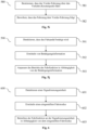
- a method for providing a driving function for automated longitudinal guidance of a vehicle at a signaling unit comprises detecting, on the basis of environmental data, a first signaling unit that is located in front of the vehicle on the roadway traveled by the vehicle in the direction of travel. Furthermore, the method comprises determining that there is a contradiction between the first signaling unit detected on the basis of the environmental data and the map data relating to the road network traveled by the vehicle. The method further comprises, in response thereto, causing an unavailability output to the user in order to inform the user that the first signaling unit detected on the basis of the environmental data is not taken into account in the driving function for the automated longitudinal guidance of the vehicle.
- a (road) motor vehicle in particular a passenger car or a truck or a bus or a motorcycle
- a (road) motor vehicle in particular a passenger car or a truck or a bus or a motorcycle
- SW software program
- the SW program can be configured to be executed on a processor (e.g. on a control unit of a vehicle) and thereby to carry out at least one of the methods described in this document.
- the storage medium can comprise a software program which is designed to be executed on a processor and thereby to carry out at least one of the methods described in this document.
- automated driving in the context of this document can be understood as driving with automated longitudinal or lateral guidance or autonomous driving with automated longitudinal and lateral guidance.
- Automated driving can, for example, be driving on the motorway for a longer period of time or driving for a limited period of time when parking or maneuvering.
- automated driving includes automated driving with any degree of automation. Examples of degrees of automation are assisted, partially automated, highly automated or fully automated driving. These Degrees of automation were defined by the Federal Highway Research Institute (BASt) (see BASt publication " Research compact", issue 11/2012 ). In assisted driving, the driver permanently carries out longitudinal or lateral guidance, while the system takes over the other function within certain limits.
- assisted driving the driver permanently carries out longitudinal or lateral guidance, while the system takes over the other function within certain limits.
- the system takes over longitudinal and lateral guidance for a certain period of time and/or in specific situations, whereby the driver must permanently monitor the system, as in assisted driving.
- highly automated driving HAF
- the system takes over longitudinal and lateral guidance for a certain period of time without the driver having to permanently monitor the system; however, the driver must be able to take over vehicle control within a certain time.
- fully automated driving VAF
- the system can automatically handle driving in all situations for a specific application; for this application, a driver is no longer required.
- the four levels of automation mentioned above correspond to SAE levels 1 to 4 of the SAE J3016 standard (SAE - Society of Automotive Engineering).
- highly automated driving HAF corresponds to level 3 of the SAE J3016 standard.
- SAE J3016 also provides for SAE Level 5 as the highest level of automation, which is not included in the BASt definition.
- SAE Level 5 corresponds to driverless driving, where the system can automatically handle all situations like a human driver throughout the entire journey; a driver is generally no longer required.
- the aspects described in this document relate in particular to a driving function or a driver assistance function that are designed according to SAE Level 2.
- this document deals with increasing the reliability, availability and/or comfort of a driving function, in particular a driver assistance system, of a vehicle in connection with a signalling unit at an intersection of the carriageway or road travelled by the vehicle with another traffic route.
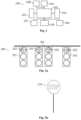
- Fig.1 shows exemplary components of a vehicle 100.
- the vehicle 100 comprises one or more environmental sensors 103 (e.g. one or more image cameras, one or more radar sensors, one or more lidar sensors, one or more ultrasonic sensors, etc.) which are set up to record environmental data in relation to an environment of the vehicle 100 (in particular in relation to the environment in the direction of travel in front of the vehicle 100).
- the vehicle 100 also comprises one or more actuators 102 which are set up to influence the longitudinal and/or transverse guidance of the vehicle 100.
- Example actuators 102 are: a braking system, a drive motor, a steering system, etc.
- the control unit 101 can be configured to perform a Driving function, in particular a driver assistance function. For example, an obstacle on the travel trajectory of the vehicle 100 can be detected on the basis of the sensor data.
- the control unit 101 can then control one or more actuators 102 (eg the braking system) in order to automatically decelerate the vehicle 100 and thereby prevent a collision of the vehicle 100 with the obstacle.
- actuators 102 eg the braking system
- one or more signaling units e.g. a traffic light and/or a traffic sign
- a traffic light and/or a traffic sign on the roadway or street traveled by the vehicle 100 can be taken into account in addition to a vehicle in front.
- the status of a traffic light or traffic light system can be taken into account so that the vehicle 100 automatically decelerates to the stop line of the traffic light at a red light relevant to its own (planned) direction of travel and/or accelerates (if necessary again) at a green light.
- Traffic lights can be constructed very heterogeneously in different countries and can also be of varying complexity with regard to the direction of travel and traffic light signal assignment. For example, different directions of travel can be controlled by a first group of signals or by a signal group, and another direction can be controlled by another signal group.
- the repeating signals of a signal group can also be geographically located at different points at an intersection. It can therefore be difficult for a control unit 101 (also referred to as a vehicle guidance system in this document) to recognize on the basis of the sensor data which one or more signals of a traffic light at an intersection are relevant for the planned direction of travel of the vehicle 100 and which are not (especially if the vehicle 100 is still relatively far away from the traffic light).
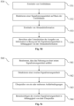
- Fig. 2a shows an example of a traffic light system 200.
- the Fig. 2a The traffic light system 200 shown has four different signal generators 201, which are are arranged at different positions on an approach to an intersection.
- the left signal head 201 has an arrow 202 pointing to the left, indicating that this signal head 201 is for left-turning vehicles.
- the two middle signal heads 201 have an arrow 202 pointing upwards (or no arrow 202), indicating that these two signal heads 201 are for straight-ahead driving.
- the individual light signals of these two signal heads 201 form signal groups.
- the right signal head 201 has an arrow 202 pointing to the right, indicating that this signal head 201 is for right-turning vehicles.
- Fig. 2b shows an example of a stop sign as a traffic sign 210, by which the right of way is regulated at a traffic junction, in particular at an intersection.
- the control unit 101 of the vehicle 100 can be set up to recognize a traffic sign 210 relevant to the right of way of the vehicle 100 on the road or lane traveled by the vehicle 100 based on the sensor data of the one or more environmental sensors 103 (ie based on the environmental data) and/or based on digital map information (ie map data).
- Fig.3 shows, by way of example, a vehicle 100 that is moving on a roadway towards a signaling unit 200, 210 (in particular towards a traffic light system 200 and/or towards a traffic sign 210).
- the one or more environmental sensors 103 of the vehicle 100 can be set up to collect sensor data (in particular image data) relating to the signaling unit 200, 210.
- the sensor data can then be analyzed (e.g. using an image analysis algorithm) to determine characteristics of one or more features of the signaling unit 200, 210. In particular, it can be determined on the basis of the sensor data whether the signaling unit 200, 210 is a traffic light system 200 or a traffic sign 210.
- the (signaling) state of the relevant signal generator 201 e.g. the color, such as red, yellow or green
- the color such as red, yellow or green
- the quality and/or reliability with which the characteristic of a feature of a signaling unit 200, 210 can be determined based on the environmental data typically depend on the distance 311 of the vehicle 100 to the signaling unit 200, 210. Furthermore, current weather conditions typically have a significant influence on the quality and/or reliability of the determined characteristic of a feature. In addition, the quality and/or reliability can be different for different features.
- the vehicle 100 can have a storage unit 104 on which digital map information (ie map data) relating to the road network traveled by the vehicle 100 is stored.
- the map data can display as attributes characteristics of one or more features of one or more signaling units 200, 210 in the road network.
- the map data for a traffic light system 200 can display the assignment of the one or more signal generators 201 or signal groups 201 to different possible directions of travel.
- the map data can display which signal generator or signal group 201 is responsible for releasing which direction of travel.
- the map data can optionally be received at the vehicle 100 by means of a communication unit 105 of the vehicle 100 via a wireless communication connection (e.g. a WLAN or LTE communication connection).
- a wireless communication connection e.g. a WLAN or LTE communication connection
- the control unit 101 of the vehicle 100 is set up (e.g. based on the current position of the vehicle 100 and on the basis of a planned route and/or on the basis of the environmental data of the one or more environmental sensors 103) to determine that the vehicle 100 is driving towards a signaling unit 200, 210 ahead. Furthermore, the control unit 101 can determine the characteristics of one or more features of the signaling unit 200, 210 ahead on the basis of the (stored and/or received) map data. In particular, it can be determined on the basis of the map data which signal generator or signal group 201 of a traffic light system 200 is assigned to the current or planned direction of travel of the vehicle 100. In addition, the current status of the assigned signal generator or the assigned signal group 201 can be determined on the basis of the environmental data.
- an automated driving function e.g. automated longitudinal guidance of the vehicle 100
- an automated driving function can then be carried out in a reliable and convenient manner.
- the characteristics of the one or more relevant features of a signaling unit 200 can be determined even at a relatively large distance 311 of the vehicle 100 from the signaling unit 200, whereby the reliability, availability and convenience of an automated driving function can be increased.
- a vehicle 100 can be set up to use information relating to a signaling unit 200, 210 that is or has been passed by the vehicle 100 to create and/or supplement the map data.
- the map data can be created and/or supplemented locally by the vehicle 100 and/or centrally by a central unit 300 (eg by a backend server) (see Fig.3 ).
- the one or more environmental sensors 103 of a vehicle 100 can typically record environmental data that precisely indicate the characteristics of one or more features of the signaling unit 200, 210.
- the recorded Environmental data can be used to determine the assignment between signal heads or signal groups 201 and possible directions of travel in a precise and reliable manner.
- the vehicle 100 can be set up to transmit the determined information (e.g. the environmental data and/or the determined characteristics of the one or more features) to the central unit 300 via a wireless communication connection 301 (in connection with an identifier for the respective signaling unit 200, 210, for example in connection with the position of the signaling unit 200, 210).
- the central unit 300 can then create and/or update map data based on the information provided by a large number of vehicles 100, which shows the characteristics of one or more features as attributes for a large number of different signaling units 200, 210.
- the map data can then be made available to the individual vehicles 100 in order to support the operation of an automated driving function (as explained above).
- the vehicle 100 includes a user interface 107 with one or more control elements and/or with one or more output elements.
- Fig.4 shows an exemplary user interface 107 with a display unit 400, in particular with a screen, for outputting visual information.
- a suggestion for automatically driving the vehicle 100 to a signaling unit 200, 210 located ahead can be output via a display element 401.
- a display element 402 can be provided, via which the status of the driving function (eg active or inactive) is displayed.
- the user interface 107 can comprise at least one loudspeaker 420 as an output element, via which an acoustic output (eg a warning tone) can be output to the driver of the vehicle 100.
- an acoustic output eg a warning tone
- the user interface 107 can comprise one or more control elements 411, 412, 413 that enable the driver of the vehicle 100 to activate and/or parameterize the driving function.
- An example control element is a rocker switch 411 that enables the driver to set a set speed (i.e. a target driving speed) for the vehicle 100, in particular to increase or reduce it.
- Another example control element is a set control element 412 that enables the driver to set the current driving speed as a set speed and/or to accept a suggestion for automatically driving the vehicle 100 at a signaling unit 200, 210 ahead.
- the user interface 107 can comprise a resume control element 413 that enables the driver, for example, to reactivate the driving function with a previously determined set speed.
- the control unit 101 of the vehicle 100 can be designed to provide automated longitudinal guidance of the vehicle 100 in urban areas.
- This driving function can be referred to, for example, as an Urban Cruise Control (UCC) driving function.
- the driving function can be provided in an automatic mode (aUCC) and/or in a manual mode (mUCC).
- aUCC automatic mode
- mUCC manual mode
- the driver can be enabled to specify via the user interface 107 whether the driving function should be operated in automatic or manual mode.
- the control unit 101 of the vehicle 100 is set up to detect a signaling unit 200, 210 ahead on the route of the vehicle 100 based on the environmental data of the one or more environmental sensors 103 and/or based on the map data (in connection with the position data of the position sensor 106 of the vehicle 100).
- a suggestion or a request can then be issued via the user interface 107 as to whether the signaling unit 200, 210 should be taken into account in the automated longitudinal guidance of the vehicle 100 or not.
- the driver of the vehicle 100 can then, e.g. by By operating the set control element 412, the user can accept or reject or ignore the crate.
- the detected signaling unit 200, 210 can be taken into account automatically (ie without any feedback required from the driver) in the automated longitudinal guidance of the vehicle 100.
- an automatic deceleration can be effected (depending on the type and/or (signaling) state of the signaling unit 200, 210) in order to automatically bring the vehicle 100 to a standstill (e.g. at a red light or at a stop sign).
- an automatic start of the vehicle 100 can be effected (e.g. after a change in the (signaling) state of the signaling unit 200, 210, for example after a change to green).
- the vehicle 100 can then be automatically accelerated back to the set speed (taking into account a specified minimum or target distance to a vehicle in front).
- the UCC driving function can thus enable the driver of a vehicle 100 to use the ACC driving function even on a road with one or more signaling units 200, 210 (without having to deactivate and reactivate the ACC function on the individual signaling units 200, 210).
- the control unit 101 of the vehicle 100 is set up to determine, based on the environmental data and/or on the map data, whether or not a signaling unit 200, 210 located ahead can be taken into account in the automated longitudinal guidance. If it is determined that the signaling unit 200, 210 located ahead cannot be taken into account in the automated longitudinal guidance, an output (eg an optical output via a display unit 400, 402) will be sent to the driver of the vehicle 100 in order to inform the driver of the vehicle 100 of this. inform that the signaling unit 200, 210 ahead cannot be taken into account in the automated longitudinal guidance. This indication is referred to as an "unavailability indication". It is then the task of the driver of the vehicle 100 to slow down the vehicle 100 in front of the signaling unit 200, 210 if necessary (e.g. because the traffic light turns red or because the signaling unit 200, 210 is a stop sign).
- control unit 101 can be configured to detect during operation of the UCC driving function that the vehicle 100 can no longer be automatically guided longitudinally (e.g. because the driver has manually intervened in the longitudinal guidance of the vehicle 100).
- a takeover request i.e. a takeover request, TOR
- TOR can be issued to the driver of the vehicle 100 in order to prompt the driver to manually take over the longitudinal guidance of the vehicle 100.
- the vehicle 100 may include one or more driver sensors 108 configured to capture sensor data relating to the driver of the vehicle 100 (these sensor data are also referred to as driver data in this document).
- An exemplary driver sensor 108 is a camera aimed at the driver position of the vehicle 100.
- the control unit 101 may be configured to determine, based on the driver data, whether or not the driver is paying sufficiently high attention to the driving task or to monitoring the driving function. Alternatively or additionally, the driver's level of attention to the driving task or to monitoring the driving function may be determined. Furthermore, the control unit 101 may be configured to operate the driving function, in particular the UCC driving function, depending on the determined level of attention of the driver. In this way, the comfort and safety of the driving function can be further increased.
- control unit 101 is configured to inform the driver about the unavailability of the automated longitudinal guidance support at the detected signaling unit 200, 210 (e.g. by means of an optical, haptic and/or acoustic output via the user interface 107) if the signaling unit 200, 210 was detected only on the basis of the environmental data but not on the basis of the map data.
- the control unit 101 can thus be set up to offer and/or provide automated support for the longitudinal guidance at the recognized signaling unit 200, 210 only if the signaling unit 200, 210 is recognized not only based on environmental data but also based on map data. If the automated support for the longitudinal guidance at the recognized signaling unit 200, 210 is not can be provided, the driver is informed via the user interface 107 about the unavailability of the automated support (through an unavailability output). This enables safe operation of the UCC driving function. In particular, this can reliably prevent the stop line of a recognized signaling unit 200, 210 from being crossed in an impermissible manner because the driver falsely assumes that he will be supported in the longitudinal guidance at the recognized signaling unit 200, 210.
- a signal group 201 can include all synchronized traffic lights or signal generators of a traffic light system 200. At an intersection with separately switched traffic lights for left-turners on the one hand and for straight-ahead or right-turners on the other hand, there is thus an access with two different signal groups 201.
- the control unit 101 can be set up to provide the automatic mode of the UCC driving function, i.e. aUCC, possibly only at a traffic light system 200 with a single signal group 201.
- the manual mode of the UCC driving function i.e. mUCC
- the driver receives a suggestion for support with longitudinal guidance via the user interface 107, which the driver can then accept by operating a control element 412 of the user interface 107 (which leads, for example, to automated braking at a red signal group 201).
- the driving function knows when approaching a traffic light system 200 how many different signal groups 201 the traffic light system 200 has and with which function characteristic (aUCC or mUCC) the traffic light system 200 can be reacted to, the number of signal groups 201 can be specified as Map attribute must be stored in the map data (ie in the digital map information). Since this map data can be incorrect in individual cases or the number of signal groups 201 can change due to reconstruction measures, a situation can arise in which the UCC driving function (based on the map data) assumes a traffic light system 200 with only one signal group 201 for a signaling unit 200, 210 ahead, but two different traffic light colors are recognized based on the environment data.
- aUCC or mUCC function characteristic
- map attributes in relation to a signaling unit 200, 210 differ from what is detected on the basis of the environmental data recorded by the vehicle 100, this may be because the map attributes are incorrect or because the environmental data are misinterpreted (false positive). A false positive of the environmental data is often only present for a relatively short period of time.
- control unit 101 can be set up to repeatedly check the situation in response to a detected deviation or in response to a detected contradiction between environmental data and map data before a vehicle reaction occurs (in particular before an unavailability output is triggered or before the driving function is operated in manual mode). By repeatedly checking, it may be possible to resolve the contradiction and thus enable an improved reaction of the driving function to the situation.
- This delayed reaction can be delayed until a decision point in time or until a decision position that is as close as possible to the detected signaling unit 200, 210, but which still leaves enough time to be able to safely react to the signaling unit 200, 210 automatically and/or manually even after the delayed reaction.
- the UCC driving function is used when approaching a traffic light 200, which according to the map data only has one signal group 201, based on the surrounding data several different traffic light colors are detected, the decision as to whether manual or automatic braking can be carried out on the traffic light system 200 (i.e. whether mUCC or aUCC is carried out) can be delayed. This is possible if the signal group deviation is detected early enough that even after a delayed reaction, a safe reaction to the traffic light system 200 can still be carried out. If a signal group deviation is detected, in this case the driving function does not initially react to the traffic light system 200.
- an mUCC offer is preferably issued if the deviation or contradiction between the surrounding data and the map data still exists.
- a (temporary) false positive of the surrounding data can be assumed and the driving function can automatically (in aUCC mode) regulate to the traffic light system 200.
- the control unit 101 can thus be set up to determine a decision point in time or a decision position in front of a recognized signaling unit 200, 210 at which a decision must be made at the latest as to whether the UCC driving function is operated in automatic mode or in manual mode. If at the decision point in time or at the decision position there is a contradiction between the environmental data-based detection of the signaling unit 200, 210 and the map data-based detection of the signaling unit 200, 210, the UCC driving function can be operated in manual mode. If there is no contradiction, the UCC driving function can be operated in automatic mode. This can increase the comfort and safety of the UCC driving function.
- the control unit 101 can thus be set up to decide in a flexible manner whether the UCC driving function can be operated in automatic mode or in manual mode for a recognized signaling unit 200, 210.
- the UCC driving function can thus be operated in mixed operation with automatically performed automated braking and manual offers for performing automated braking.
- automated braking can be performed automatically, or the need for driver confirmation can be recognized before performing automated braking.
- control unit 101 can be set up to flexibly decide on the basis of the map data and on the basis of the environmental data whether the UCC function on a recognized signaling unit 200, 210 is to be operated in automatic mode or in manual mode. In particular, a decision can be made as to whether a recognized intersection can be safely controlled in an automated manner or not, and/or whether the relevant signal group 201 for the vehicle 100 can be determined or not.
- automated braking can be initiated automatically (without confirmation by the driver of the vehicle 100).
- the automatic initiation of automated braking can be communicated to the driver via the user interface 107, e.g. via the instrument cluster.
- the flexible operation of the UCC driving function in automatic mode or in manual mode can increase the comfort, safety and availability of the UCC driving function.
- the driver of the vehicle 100 can be enabled to configure the UCC driving function via the user interface 107.
- the driver can, for example, specify whether the UCC driving function should be operated (if possible) in automatic mode (aUCC) or whether the UCC driving function should generally only be operated in manual mode (mUCC).
- aUCC automatic mode
- mUCC manual mode
- the configuration or the change of the configuration can, for example, take place at a configuration time or at a configuration position (within the lane or road network).
- the control unit 101 can be set up to implement the change in the configuration of the driving function brought about at the configuration time or at the configuration position only when the driving function is operated. take into account when the vehicle 100 is in a state in which the configuration changes do not cause an immediate vehicle reaction.
- a configuration change via the user interface 107 that could cancel active braking on a specific signaling unit 200, 210 can only be accepted when the active braking has ended or when the active braking has been canceled due to other influences (e.g. due to cancellation by the driver).
- the configuration change therefore only affects the next driving situation with a signaling unit 200, 210. If the UCC driving function is deactivated (e.g. by the passenger) during active traffic light braking on a traffic light 200, the vehicle 100 continues to brake until it comes to a standstill in front of the traffic light 200. The driving function is only actually deactivated after braking.
- aUCC automatic takeover
- mUCC manual takeover
- the control unit 101 can thus be set up to check whether a signaling unit 200, 210 for the UCC driving function has already been recognized at the configuration time or at the configuration position of a configuration change of the UCC driving function and/or whether automated longitudinal guidance has already taken place with respect to a recognized signaling unit 200, 210. If this is the case, the configuration change may only be taken into account for the directly following signaling unit 200, 210 (and not for the signaling unit 200, 210 that has already been recognized and/or taken into account). In particular, deactivation of the driving function may only take place after completion of the automated longitudinal guidance in relation to the already recognized signaling unit 200, 210. This can ensure particularly safe operation of the UCC driving function.
- control unit 101 can be set up to detect a signaling unit 200, 210 located in the direction of travel in front of the vehicle 100 on the basis of the environmental data (and possibly on the basis of the map data). Furthermore, the color of a signal group 201 of the signaling unit 200, 210 can be determined on the basis of the environmental data.
- the duration threshold value and/or the distance threshold value can be speed-dependent or speed-independent.
- the duration threshold value and/or the distance threshold value can be set in such a way that for durations longer than the duration threshold value and/or for distances greater than the distance threshold value, manual braking of the vehicle 100 by the driver to stop the vehicle 100 at the detected signaling unit 200, 210 is still possible and/or sensible. For example, a maximum possible deceleration of the vehicle 100 and/or a predefined reaction time of the driver can be taken into account.
- the control unit 101 can thus be set up to ensure that, due to false detection and/or due to a traffic light that switches to yellow late in an area that is not relevant for the driver, no Unavailability Indicator (NVA) is issued, since the issuance of such an NVA would represent an additional disturbance for the driver.
- NVA Unavailability Indicator
- the minimum distance x to the stop position of the traffic light 200 can be independent of speed and can possibly represent a lower limit. Below this distance value, the NVA may then generally not be displayed.
- the time criterion can be speed-dependent. This criterion can then result in the NVA not being output, particularly at relatively high speed ranges.
- the UCC driving function can be operated in a manual mode in which the driver of the vehicle 100 is given an offer to assist with longitudinal guidance at a recognized signaling unit 200, 210.
- the driver of the vehicle 100 then has the option of accepting the offer (e.g. by operating the set control element 212). If the offer is accepted, automated braking can be carried out at the recognized signaling unit 200, 210 if necessary.
- the next signalling unit 200, 210 ahead is already detected at a relatively large (temporal and/or spatial) distance 311 before reaching the signalling unit 200, 210 (based on the environment data).
- the detected signalling unit 200, 210 may still be irrelevant for the longitudinal guidance of the vehicle 100 and/or for the driver of the vehicle 100.
- An output to the driver of the vehicle 100 e.g. in relation to an offer to support the automated longitudinal guidance at the recognized signaling unit 200, 210, could be perceived by the driver as disturbing and/or irritating.
- the signaling unit 200, 210 is covered at a later point in time and is therefore no longer recognized. This could lead to the offer to the driver being withdrawn and thus to confusion for the driver.
- the control unit 101 can be configured to determine whether the (spatial and/or temporal) distance 311 to a detected signaling unit 200, 210 is equal to or greater than an output threshold. Furthermore, the control unit 101 can be configured to only cause an output in relation to the detected signaling unit 200, 210 (e.g. an offer to take the detected signaling unit 200, 210 into account in the automated longitudinal guidance) when the (spatial and/or temporal) distance 311 to the detected signaling unit 200, 210 is equal to or smaller than the output threshold.
- an output in relation to the detected signaling unit 200, 210 e.g. an offer to take the detected signaling unit 200, 210 into account in the automated longitudinal guidance
- the control unit 101 can thus be set up to take into account a required minimum output distance to a recognized signaling unit 200, 210.
- a missing condition with regard to a minimum output distance could lead to irritation for the driver, since implausible changes with regard to an offer to support the automated longitudinal guidance at the recognized signaling unit 200, 210 could be displayed on the screen 400 (e.g. in the instrument cluster and/or in the head-up display), although the signaling unit 200, 210 (e.g. a red traffic light) is not (yet) relevant to the driver.
- Such changes could be caused, for example, by uncertainties in the camera detection (due to the relatively high distance).
- the control unit 101 can be configured to only issue an offer with respect to a signaling unit 200, 210 if a certain distance to the signaling unit 200, 210 is not exceeded. If necessary, no display is made if the vehicle 100 is in the xth row (with x> 1) in front of the signaling unit 200, 210. Incorrect and/or implausible displays can thus be eliminated.
- the control unit 101 can thus be set up to suppress the output of an offer as long as the predefined output distance 311 to the signaling unit 200, 210 is not exceeded. In this way, the comfort for the user can be increased.
- the control unit 101 can be set up to sequentially search for a (directly) subsequent second signaling unit 200, 210 after the support of the longitudinal guidance of the vehicle 100 has ended at a first signaling unit 200, 210, which can or should be taken into account in the longitudinal guidance of the vehicle 100.
- a suggestion for the consideration of a subsequent second signaling unit 200, 210 can be issued.
- the subsequent second signaling unit 200, 210 can be automatically taken into account (and an associated automated braking process can be carried out, if necessary).
- the detection of a subsequent second signaling unit 200, 210 can be impaired, in particular when approaching a traffic light (i.e. at a first signaling unit 200, 210) (e.g. because the environment data still partially display information relating to the first signaling unit 200, 210). This can lead to a driving function behavior that is implausible for the driver of the vehicle 100.
- the control unit 101 can thus be set up to suppress all manual and/or automatic offers for consideration of signaling units 200, 210 for a defined period of time after the vehicle 100 has started moving. Alternatively or additionally, it may be necessary for a minimum speed of the vehicle 100 to be exceeded in order to allow a manual and/or automatic offer.
- a blocking timer can be started that suppresses all offers up to a defined time from the start of the "driving" state. Furthermore, no offers may be issued up to a defined speed. This can further increase the comfort of the driving function.
- the vehicle 100 may include one or more driver sensors 108 configured to capture driver data (i.e., sensor data) relating to the driver of the vehicle 100.
- driver data i.e., sensor data
- the UCC driving function may be operated depending on the driver data. In particular, information may be output to the driver of the vehicle 100 depending on the driver data or may be prevented.
- the control unit 101 of the vehicle 100 may be configured to determine, based on the driver data, whether the driver is sufficiently attentive with respect to the driving task or in relation to the monitoring of the driving function or not. Furthermore, the control unit 101 can be configured to supplement an unavailability indication (NVA) displayed on the screen 400 of the user interface 107 by outputting an optical and/or haptic signal if it is determined that the driver is not sufficiently attentive. In this way, the comfort and safety of the UCC driving function can be increased.
- NVA unavailability indication
- the unavailability display can be issued, for example, if it is detected that the driving function (e.g. due to late detection of a traffic light, due to the traffic light switching to yellow late, due to a covered camera 103, etc.) can no longer react to the traffic light in time (and thus automated braking at the traffic light is not available).
- the NVA can be displayed, for example, in the instrument cluster and/or in the head-up display. If the driver is inattentive at the time the NVA is issued, this could lead to the driver overlooking the visual indication (and continuing to assume that the traffic light 200 is taken into account in the automated longitudinal guidance).
- an acoustic signal can be given to the driver who is identified as being inattentive, for example, to prompt the driver to pay attention.
- a steering wheel vibration and/or activation of light strips on the steering wheel can be triggered. This can ensure that the traffic light for which NVA is displayed is not overlooked by the driver.
- the driver's state can be determined using a driver model. If it is detected that the driver is inattentive, a sound can be emitted in addition to the unavailability display. Alternatively or in addition, additional haptic or further optical feedback can be provided.
- a change in the driving behavior of the vehicle 100 can occur.
- the driving function can automatically abort a braking process that has already been initiated, e.g. in order to accelerate the vehicle 100 again. This can occur, for example, within the scope of the UCC driving function if, during automated braking at a traffic light system 200 with a red signal group 201, the signal group 201 changes to green.
- the change in the driving behavior of the vehicle 100 caused by the driving function can be perceived as unsettling and/or uncomfortable for the driver of the vehicle 100, in particular if the driver of the vehicle 100 is inattentive.
- the control unit 101 can be configured to determine that the driving behavior of the vehicle 100 caused by the driving function of the vehicle 100 has changed significantly or will change significantly at a certain point in time. Furthermore, the control unit 101 can be configured to determine, based on the driver data from the one or more driver sensors 108, that the driver of the vehicle 100 is inattentive to the driving task at the point in time of change. In response, information indicative of the change in driving behavior can be output to the driver of the vehicle 100 (e.g. via a visual and/or acoustic output). This can increase the comfort for the driver of the vehicle 100.
- the control unit 101 can thus be configured to inform a driver who is recognized as inattentive visually and/or acoustically and/or haptically about the change when the driving function significantly changes its characteristics, e.g. braking is aborted and the vehicle accelerates back into free travel.
- the control unit 101 can cause the UCC driving function to abort braking and switch to free travel or following travel (if there is a vehicle ahead), particularly if the driver is recognized as being attentive via the interior camera 108. If the driver is not recognized as being attentive in this situation, the driver can be notified of the changed conditions, e.g. via a gong, acoustically and/or visually. For safety reasons, braking can then be continued despite the green traffic light until the driver is recognized as being attentive again. This can further increase the safety of the driving function.
- NCA unavailability display
- the driving function typically does not initiate braking and instead displays an unavailability display to the driver. If the driver does not brake independently in this situation, a red traffic light 200 could be driven through. For this reason, the driver's attention (particularly via the interior camera 108) can be checked (particularly at the same time) when the unavailability display is output. If the driver is detected as inattentive, an acoustic gong can be output to alert the driver that no braking is being carried out by the UCC driving function and that a driver reaction may be necessary. This can increase the safety and comfort of the driving function.
- the control unit 101 of the vehicle 100 can be set up to adapt the deceleration and/or acceleration of the vehicle 100 that is automatically effected as part of a driving function, in particular as part of the UCC driving function, in particular the temporal progression of the deceleration and/or acceleration, depending on the driver data, in particular depending on the detected level of attention of the driver. In this way, the comfort and safety of the driving function can be increased.
- braking can be started with a jolt, which causes a haptic signal to be sent to the driver (who is recognized as inattentive) as an indication to focus attention on the driving task.
- the time course of a deceleration and/or an acceleration of the vehicle 100 can depend on a set driving mode (e.g. sporty, comfort and/or energy-saving). For example, it can be possible (e.g. in a sport mode) to start decelerating the vehicle 100 at a later point in time and/or to carry it out with an increased deceleration value if the driver of the vehicle 100 is recognized as being attentive. In this way, the comfort and safety of a driving function can be increased.
- a set driving mode e.g. sporty, comfort and/or energy-saving
- the control unit 101 can be set up to determine (in particular on the basis of the environment data and/or on the basis of the map data) the type of signaling unit 200, 210 (from a predefined set of different types).
- Example types are a Traffic light system 200 or a traffic sign 210.
- the control unit 101 can be set up to predict (in particular on the basis of the environmental data and/or on the basis of the map data) duration information with respect to the duration that the vehicle 100 must probably stop at the signaling unit 200, 210 ahead before the vehicle 100 can start moving again.
- stopping information with respect to the stop of the vehicle 100 at the signaling unit 200, 210 ahead can be determined.
- a relatively fast deceleration process can be selected at a stop sign 210, since the vehicle 100 can continue driving immediately after stopping (if the traffic on the crossing road allows it).
- the comfort of the driving function can be increased.
- the vehicle 100 is normally controlled until it comes to a standstill.
- a different deceleration curve can be used depending on the type of signaling unit 200, 210.
- the automated braking at a traffic light 200 can differ from the automated braking at a stop sign 210. (because the driver may be able to continue driving immediately after stopping at a stop sign 210).
- the driving style, in particular the deceleration or the deceleration characteristics, of the vehicle 100 can be selected by the user of the vehicle 100 using the driving experience switch.
- the driving function can adopt different deceleration profiles on traffic lights 200 and/or stop signs 210 using the driving experience switch (e.g. Eco, Comfort, Sport, etc.).
- the different deceleration profiles can be brought about by adjusting one or more parameters in the trajectory planning of the vehicle 100.
- the comfort and safety of the driving function can be increased.
- any impairment of the following traffic can be avoided, which could arise, for example, if the deceleration is too slow in front of a stop sign 210.
- the driver of the vehicle 100 can be shown via the user interface 107, in particular on the screen 400, a signaling unit 200, 210 ahead on the roadway traveled by the vehicle 100, at which the vehicle 100 must stop.
- a signaling unit 200, 210 ahead on the roadway traveled by the vehicle 100 at which the vehicle 100 must stop.
- the symbol of a red traffic light or a stop sign can be displayed on the screen 400.
- an acoustic output can be triggered in relation to the detected signaling unit 200, 210.
- An automated braking process of the vehicle 100 can then be triggered automatically (aUCC) or after confirmation by the driver (mUCC) until it comes to a standstill at the signaling unit 200, 210, in particular up to the stop line of the signaling unit 200, 210.
- the control unit 101 can be configured (based on the acquired environmental data) to determine the (signaling) state, in particular the color, which is required for the Vehicle 100 relevant signal group 201 of the signaling unit 200, 210 while the vehicle 100 is at the signaling unit 200, 210. Furthermore, the control unit 101 can be set up to change the display with respect to the signaling unit 200, 210 or to delete it completely or to withdraw it (and/or to cause an acoustic output) when a phase change of the signal group 201 from red to green is detected and/or as soon as the vehicle 100 has come to a standstill at the signaling unit 200, 210.
- the driver of the vehicle 100 can be clearly informed that the signaling unit 200, 210 is no longer relevant for the longitudinal guidance of the vehicle 100.
- the withdrawal of the display can be effected in the automatic mode and/or in the manual mode of the UCC driving function.
- the driver of the vehicle 100 can be enabled to start the vehicle 100 at the signaling unit 200, 210 (in particular after a phase change from red to green has been detected) using an operating element 413 (e.g. using the resume button) of the user interface 107.
- the driver can be enabled to accelerate the vehicle 100 back to the set set or target speed by operating the operating element 413 (taking into account a set target distance to a vehicle in front).
- Starting at the signaling unit 200, 210 by operating the (resume) operating element 413 can be enabled in the automatic mode and/or in the manual mode of the UCC driving function.
- 210 can be effected by operating the accelerator pedal of the vehicle 100. However, this can lead to an interruption of the UCC driving function.
- a control element 413 in particular via a button
- a convenient continuation of the UCC driving function is thus possible in a sequence of consecutive signaling units 200, 210 (in automatic mode and/or in manual mode of the UCC driving function).
- the UCC driving function can be designed in such a way that at a (possibly manually confirmed) traffic light 200 (mUCC) after a standstill and after a green change is detected, the display in relation to the traffic light 200 is withdrawn.
- the driver can be enabled to drive off using button 413. This can increase the convenience of the UCC driving function.
- consistent behavior with the ACC driving function (at a standstill without a vehicle in front) can be achieved.
- the control unit 101 can be set up to cause a timer to be activated at a (possibly manually confirmed) traffic light 200 from the start of the phase change detection to green, which causes the red display in relation to the traffic light 200 to be removed from the standstill of the vehicle 100.
- the control unit 101 of the vehicle 100 can be set up to block or prevent the vehicle 100 from starting at a signaling unit 200, 210 in response to the actuation of an operating element 411, 412, 413 of the user interface 107 if it is detected that the vehicle 100 is arranged in the first row at the signaling unit 200, 210.
- starting by actuating an operating element 411, 412, 413 of the user interface 107 can possibly only be made possible if at least one other vehicle 100 in front of the vehicle 100 is at the signaling unit 200, 210. In this way, the safety of the UCC driving function can be increased.
- this can reliably prevent the driver of the vehicle 100 from causing the vehicle to start moving at a (possibly red) traffic light 200 by unconsciously operating a control element 411, 412, 413 of the user interface 107 (in particular the rocker switch 411 and/or a button 412, 413).
- the control unit 101 of the vehicle 100 can be set up to determine, based on the environmental data and/or on the basis of the position data (in connection with the map data), whether the vehicle 100 is in the first row at a signaling unit 200, 210 or not. In particular, the distance of the vehicle 100 to the stopping point or to the stopping line of the signaling unit 200, 210 can be determined. Based on the determined distance, it can then be determined whether the vehicle 100 is in the first row or not.
- the state of the signaling unit 200, 210 in particular the color of a signal group 201 of the signaling unit 200, 210, cannot be recognized or cannot be recognized reliably on the basis of the environmental data of one or more environmental sensors 103 of the vehicle 100. This could lead to a reduced availability of the UCC driving function.
- the control unit 101 can be set up to detect the vehicle in front driving (directly) in front of the vehicle 100 on the basis of the environmental data.
- the UCC driving function in particular the automated longitudinal guidance of the vehicle 100, can then be carried out or provided on the signaling unit 200, 210 on the basis of the driving behavior of the vehicle in front. By taking the driving behavior of the vehicle in front into account when By operating the UCC driving function, the availability and thus the comfort of the driving function can be increased.
- the UCC driving function it may happen, for example, that the color of a traffic light 200 cannot be adequately recognized due to obscuration or poor lighting conditions. Furthermore, in the case of a complex intersection geometry (with different signal groups 201), it may not be possible to assign the various signal groups 201 to the individual directions of travel. To increase the level of automation of the longitudinal control function and consequently to increase comfort for the driver, the behavior of the vehicle in front can also be evaluated and taken into account when operating the driving function, if necessary in addition to the traffic light colors and/or the attributes of a signaling unit 200, 210 from the map data.
- the vehicle in front drives over the traffic light 200 ahead, which could potentially be green
- the vehicle in front can be followed if necessary.
- automated braking can be canceled if necessary as long as a potentially relevant green traffic light is detected based on the environment data.
- the control unit 101 can be set up to detect on the basis of the environment data whether at least one of the signal groups 201 of the traffic light system or traffic light 200 ahead has a green color.
- the vehicle 100 can also be caused to drive over the traffic light system 200 (even if it could not be clearly determined on the basis of the environment data and the map data whether the signal group 201 with the green color is relevant for the direction of travel of the vehicle 100).
- the availability of the driving function can be increased in a safe manner.
- control unit 101 can be set up to assume that the traffic light 200 has switched from red to green (or is switched off in the case of on-demand traffic lights) when visibility of the traffic light 200 is lost when the vehicle 100 is stationary and a vehicle in front is moving. An automated starting process of the vehicle 100 can then be initiated. In other words, the control unit 101 can be set up to recognize that the vehicle in front, which is (directly) in front of the vehicle 100 at a signaling unit 200, 210, is moving. An automated starting process of the vehicle 100 can then be initiated, even without recognizing the (signaling) state of the signaling unit 200, 210 (possibly only after the driver of the vehicle 100 has actuated a control element 411, 412, 413). In this way, the availability of the UCC driving function can be increased in a safe manner.
- the driver of the vehicle 100 typically has the option of overriding the automated longitudinal guidance of the UCC driving function by operating the accelerator pedal and/or the brake pedal.
- the detected operation of the accelerator pedal and/or the brake pedal can also be used to terminate the UCC driving function.
- the automatic termination of the UCC driving function in response to a detected operation of the accelerator pedal and/or the brake pedal of the vehicle 100 can lead to reduced comfort and/or reduced safety of the UCC driving function.
- the stopping position of the vehicle 100 at a signaling unit 200, 210, in particular at the stop line of a signaling unit 200, 210 is perceived by the driver of the vehicle 100 as being too far in front of the signaling unit 200, 210 (in particular if the vehicle 100 is in the first row in front of the stop line and thus has no vehicle in front).
- the driver could be inclined to drive the vehicle 100 closer to the stop line by operating the accelerator pedal, which could, however, lead to the UCC driving function being aborted. and/or which may prevent automated starting as part of the driving function.
- the driver of the vehicle 100 could be inclined to change from a standstill in a first lane before a traffic light 200 to an adjacent lane (e.g. to reduce the distance to the stop line).
- the driver would press the accelerator pedal to drive the vehicle 100 into the adjacent lane. This could lead to the termination of the UCC driving function and thus to a lack of longitudinal guidance support when subsequently starting at the traffic light 200.
- a signaling unit 200, 210 detected by the UCC driving function is not taken into account in the automated longitudinal guidance of the vehicle 100 (and may be driven over without automated braking) if the driver presses the accelerator pedal at the time of detection of the signaling unit 200, 210 (and therefore the support of the UCC driving function is terminated).
- the driver of the vehicle 100 should be possible for the driver of the vehicle 100 to override the UCC driving function in a reliable and convenient manner (in particular by operating the accelerator pedal), e.g. in the event of incorrect braking of the driving function.
- the control unit 101 can be set up to determine deflection information in relation to the deflection, in particular in relation to the extent of the deflection, of the accelerator pedal.
- the deflection information can be determined, for example, on the basis of an accelerator pedal sensor of the vehicle 100.
- the control unit 101 can be set up to determine time information in relation to the duration of the actuation of the accelerator pedal. It can then be determined on the basis of the deflection information and/or on the basis of the time information whether the support of the automated longitudinal guidance of the vehicle 100 is provided to a signaling unit 200, 210 or not and/or whether the driving function is terminated or not.
- control unit 101 can be configured to determine, based on the deflection information, whether the deflection of the accelerator pedal is greater or smaller than a deflection threshold value (e.g., 25% of the maximum possible deflection of the accelerator pedal). Furthermore, the control unit 101 can be configured to determine, based on the time information, whether the duration of the deflection of the accelerator pedal is greater or smaller than a time threshold value (e.g., 4 seconds).
- a deflection threshold value e.g. 25% of the maximum possible deflection of the accelerator pedal.
- time threshold value e.g., 4 seconds
- the shedding or termination can only refer to the next signaling unit 200, 210 that follows the operation of the accelerator pedal. This means that only a temporary shedding or a temporary termination of the UCC driving function can be effected (only for the signaling unit 200, 210 that directly follows the operation of the accelerator pedal).
- this can enable the driver of the vehicle 100 to drive the vehicle 100 closer to the stop line and/or into an adjacent lane in front of a signaling unit 200, 210 by (lightly) pressing the accelerator pedal (without the automated support of the UCC driving function, for example for the subsequent starting of the vehicle 100, being terminated).
- this can ensure that a recognized signaling unit 200, 210 is taken into account in the automated longitudinal guidance of the vehicle 100 even if the driver briefly and relatively lightly presses the accelerator pedal (while the signaling unit 200, 210 is recognized).
- this can enable a comfortable and safe override of an intervention by the UCC driving function.
- the driving function can thus be designed in such a way that the driving function is immediately cancelled (only) when a certain accelerator pedal angle is exceeded.
- the driving function can also be cancelled when a certain time threshold for the actuation of the accelerator pedal is exceeded (even if the deflection threshold is not exceeded).
- the time until the time threshold is reached can be used by the driver to approach the stop line at an intersection.
- the driving function can be designed in such a way that the driving function is not interrupted if a traffic light 200 is detected while the accelerator pedal is being depressed. In this way, driving through the traffic light 200 without reacting can be reliably prevented.
- the control unit 101 can be set up to determine speed data relating to the driving speed of the vehicle 100 during a start-up process that the driver of the vehicle 100 initiates by operating the accelerator pedal. Furthermore, the control unit 101 can be set up to take over the automated longitudinal guidance from the driver as long as the driving speed caused by the actuation of the accelerator pedal has not yet exceeded a predefined speed threshold. The output of a TOR and/or the termination of the UCC driving function can thus be suppressed and/or prevented until the speed threshold is reached (and the longitudinal guidance can be taken over by the driving function). On the other hand, the output of the TOR and/or the termination of the UCC driving function can be initiated when (in particular as soon as) the speed threshold (e.g. 10 km/h) is reached or exceeded. In this way, the comfort for the driver of the vehicle 100 can be further increased.
- the speed threshold e.g. 10 km/h
- the driving mode can be set by the user of the vehicle 100, for example via the user interface 107, e.g. via one or more control elements of the user interface 107.
- the control unit 101 can also be set up to operate the UCC driving function depending on the set driving mode.
- the driving behavior such as the deceleration behavior
- the point in time at which the vehicle 100 responds to a recognized signaling unit 200, 210 can be adapted depending on the driving mode.
- the eco driving mode for example, a particularly early reaction of the vehicle 100 can be brought about, while in the comfort driving mode a reaction is only brought about later, and in the sport driving mode the reaction is brought about even later.
- the system can first switch to sailing mode, then to towing mode and finally to braking mode.
- the sailing mode can be dispensed with if necessary and the towing mode and then the braking mode can be initiated directly.
- the sailing mode and towing mode can be dispensed with if necessary and the braking mode can be initiated directly.
- the deceleration behavior of the vehicle 100 when approaching a signaling unit 200, 210 can therefore be adapted to the set driving mode. In this way, the comfort of the vehicle 100 can be further increased.
- the control unit 101 can thus be set up to vary the (output) time for reacting to a traffic light depending on the set driving mode.
- the traffic light control can begin relatively early, e.g. with an operating sequence: coasting mode, towing mode and braking mode.
- a medium start time can be selected for the traffic light control, e.g. with an operating sequence of towing mode and braking mode.
- the traffic light control can begin relatively late, e.g. directly with braking mode.
- the traffic light control (in particular the deceleration of the vehicle 100) can be made particularly comfortable by adapting it to the driving mode. Furthermore, a proactive driving style can be represented "by taking your foot off the accelerator early", which reduces the dynamics on a stationary target object in advance. This can result in a gain in comfort and safety for the driver of the vehicle 100.
- a driving mode e.g. Eco, Comfort and Sport
- a (driving and/or deceleration) characteristic can be set that is adapted to the driving mode.
- a particularly harmonious interaction between the ACC function and the UCC driving function can be made possible.
- Fig. 5a shows a flow chart of an exemplary (possibly computer-implemented) method 500 for providing a driving function (in particular the UCC driving function) for the automated longitudinal guidance of a vehicle 100.
- a driving function in particular the UCC driving function
- the method 500 comprises, during operation of the driving function, determining 501 data relating to a first signaling unit 200, 210 located ahead in the direction of travel of the vehicle 100.
- environmental data from one or more environmental sensors 103 of the vehicle 100 and/or map data relating to the road network traveled by the vehicle 100 can be determined as data.
- the method 500 includes operating 502 the driving function on the first signaling unit 200, 210 depending on the data relating to the first signaling unit 200, 210 in an automatic mode or in a manual mode.
- the first signaling unit 200, 210 can be taken into account in the automated longitudinal guidance of the vehicle 100, possibly automatically, and in the manual mode, possibly only after confirmation by a user of the vehicle 100.
- the driving function can be operated in automatic mode if, based on the data, the vehicle's direction of travel 100 relevant color of a signal group 201 of the signaling unit 200, 210 can be clearly determined. If the color of the relevant signal group 201 cannot be clearly determined, the manual mode can be used if necessary.
- the automatic mode or the manual mode of the driving function can therefore be used in a flexible manner depending on the data available for a signaling unit 200, 210. The flexible switching between the automatic mode and the manual mode can increase the availability and thus the convenience of the driving function.
- Fig. 5b shows a flow chart of an exemplary (possibly computer-implemented) method 510 for providing a driving function (in particular the UCC driving function) for automated longitudinal guidance of a vehicle 100 at a signaling unit 200, 210.
- a driving function in particular the UCC driving function
- the method 510 includes, during operation of the driving function, detecting 511 that at a configuration time or at a configuration position of the vehicle 100 a user of the vehicle 100 causes a configuration change of a property of the driving function (e.g. a change from the automatic mode to the manual mode, or a deactivation of the driving function).
- a configuration change of a property of the driving function e.g. a change from the automatic mode to the manual mode, or a deactivation of the driving function.
- the method 510 further comprises determining 512 that at the configuration time or at the configuration position a first signaling unit 200, 210 located ahead in the direction of travel of the vehicle 100 is already taken into account in the automated longitudinal guidance of the vehicle 100. Furthermore, the method 510 comprises taking into account 513 the configuration change only at the signaling unit 200, 210 following the first signaling unit 200, 210 in the automated longitudinal guidance of the vehicle 100 and/or only after the automated longitudinal guidance of the vehicle 100 at the first signaling unit 200, 210 has ended or been completed (e.g. only after the vehicle 100 has been braked at the first signaling unit 200, 210 until it comes to a standstill).
- the Automated longitudinal guidance for the first signaling unit 200, 210 can continue to be carried out without taking the configuration change into account. This enables particularly safe operation of the driving function.
- Fig. 5c shows a flow chart of an exemplary (possibly computer-implemented) method 520 for providing a driving function (in particular the UCC driving function) for automated longitudinal guidance of a vehicle 100 at a signaling unit 200, 210.
- a driving function in particular the UCC driving function
- the method 520 includes, during operation of the driving function, determining 521 environmental data relating to the environment of the vehicle 100 in front of the vehicle 100 in the direction of travel.
- the environmental data can have been recorded by one or more environmental sensors 103 of the vehicle 100.
- the method 520 also includes detecting 522, on the basis of the environmental data, a first signaling unit 200, 210 which is located on the roadway traveled by the vehicle 100 in front of the vehicle 100 in the direction of travel.
- the method 520 further includes determining 523 that there is a contradiction between the first signaling unit 200, 210 detected on the basis of the environmental data and the map data with respect to the road network traveled by the vehicle 100. For example, it can be recognized that the first signaling unit 200, 210 detected on the basis of the environmental data has a different (in particular a higher) number of different signal groups 201 than recorded in the map data.
- the method 520 includes, in response to the detected contradiction, causing 524 an unavailability output, in particular an NVA, to the user of the vehicle 100 in order to inform the user that the first signaling unit 200, 210 detected on the basis of the environmental data is not taken into account in the driving function for the automated longitudinal guidance of the vehicle 100. In this way, the safety of the driving function can be further increased.
- an unavailability output in particular an NVA
- Fig. 5d shows a flow chart of an exemplary (possibly computer-implemented) method 530 for providing a driving function (in particular the UCC driving function) for automated longitudinal guidance of a vehicle 100 at a signaling unit 200, 210.
- a driving function in particular the UCC driving function
- the method 530 comprises, during operation of the driving function, determining 531 environmental data relating to the environment of the vehicle 100 lying in front of the vehicle 100 in the direction of travel.
- the method 530 further comprises detecting 532, on the basis of the environmental data, a first signaling unit 200, 210 which is arranged on the roadway traveled by the vehicle 100 in front of the vehicle 100 in the direction of travel.
- the method 530 further comprises determining 533 distance information relating to the temporal and/or spatial distance 311 of the vehicle 100 to the first signaling unit 200, 210.
- the method 530 comprises causing or suppressing 534 an output of information relating to the first signaling unit 200, 210 depending on the distance information.
- the output in particular an offer for automated longitudinal guidance at the first signaling unit 200, 210) can be suppressed if the vehicle 100 is still too far away from the first signaling unit 200, 210.
- an output in particular an unavailability output
- Fig. 5e shows a flow chart of an exemplary (possibly computer-implemented) method 540 for providing a driving function (in particular the UCC driving function) for automated longitudinal guidance of a vehicle 100 at a signaling unit 200, 210.
- a driving function in particular the UCC driving function
- the method 540 includes, during operation of the driving function, determining 541 that the vehicle 100 is carrying out a start-up process at a first signaling unit 200, 210.
- the method 540 also includes detecting 542, on the basis of the environmental data from one or more environmental sensors 103 of the vehicle 100, a second signaling unit 200, 210 following the first signaling unit 200, 210, which is arranged on the roadway traveled by the vehicle 100 in front of the vehicle 100 in the direction of travel.
- the method 540 includes checking 543 whether one or more starting process conditions related to the starting process are met or not (e.g., one or more starting process conditions related to the driving speed of the vehicle 100 and/or related to the temporal or spatial distance of the vehicle 100 from the first signaling unit 200, 210).
- one or more starting process conditions related to the starting process are met or not (e.g., one or more starting process conditions related to the driving speed of the vehicle 100 and/or related to the temporal or spatial distance of the vehicle 100 from the first signaling unit 200, 210).
- the method 540 further includes taking into account 544 the second signaling unit 200, 210 in the automated longitudinal guidance of the vehicle 100 depending on whether the one or more starting process conditions are met or not.
- a second signaling unit 200, 210 that is detected in the immediate temporal or spatial proximity to the first signaling unit 200, 210 can be disregarded. In this way, the reliability and comfort of the driving function can be increased (e.g., since the output of incorrectly detected signaling units 200, 210 is avoided).
- Fig. 5f shows a flow chart of an exemplary (possibly computer-implemented) method 550 for providing a driving function (in particular the UCC driving function) for automated longitudinal guidance of a vehicle 100 at a signaling unit 200, 210.
- a driving function in particular the UCC driving function
- the method 550 includes, during operation of the driving function, the detection 551, based on the environmental data from one or more environmental sensors 103 of the vehicle 100, of a first signaling unit 200, 210 that is arranged on the roadway traveled by the vehicle 100 in front of the vehicle 100 in the direction of travel.
- the method 550 also includes the determination 552 of driver data relating to the attention of the driver of the vehicle 100 when monitoring the driving function.
- the method 550 also includes the operation 553 of the driving function in relation to the automated longitudinal guidance of the vehicle 100 at the first signaling unit 200, 210 depending on the driver data.
- the driving function can be operated in automatic mode or in manual mode depending on the driver data. In this way, the safety and/or comfort of the driving function can be increased.
- Fig. 5g shows a flow chart of an exemplary (possibly computer-implemented) method 560 for providing a driving function (in particular the UCC driving function) for automated longitudinal guidance of a vehicle 100 at a signaling unit 200, 210.
- a driving function in particular the UCC driving function
- the method 560 includes, during operation of the driving function, detecting 561 a first signaling unit 200, 210 that is arranged on the roadway traveled by the vehicle 100 in front of the vehicle 100 in the direction of travel.
- the method 560 also includes determining 562 stopping information with respect to the expected stopping time of the vehicle 100 at the first signaling unit 200, 210 and/or with respect to the type of the first signaling unit 200, 210 (and the associated expected stopping time).
- the method 560 includes causing 563 an automated deceleration of the vehicle 100 at the first signaling unit 200, 210 depending on the stop information.
- the time course The deceleration can be adjusted depending on the stop information. This can increase the comfort and/or safety of the driving function.
- Fig. 5h shows a flow chart of an exemplary (possibly computer-implemented) method 570 for providing a driving function (in particular the UCC driving function) for automated longitudinal guidance of a vehicle 100 at a signaling unit 200, 210.
- the method 570 includes, during operation of the driving function, determining 571 that the vehicle 100 is at a signaling unit 200, 210 (in particular at a red light). Furthermore, the method 570 includes recognizing 572 that the driver of the vehicle 100 is operating an operating element 411, 412, 413 (in particular a button or a rocker switch) of the user interface 107 of the vehicle 100 to control the driving function.
- the method 570 further comprises causing 573 an automated start of the vehicle 100 in response to the detected actuation of the control element 411, 412, 413. This enables a comfortable and safe start at a signaling unit 200, 210.
- Fig. 5i shows a flow chart of an exemplary (possibly computer-implemented) method 580 for providing a driving function (in particular the UCC driving function) for automated longitudinal guidance of a vehicle 100 at a signaling unit 200, 210.
- a driving function in particular the UCC driving function
- the method 580 includes, during operation of the driving function, determining 581, based on environmental data relating to a front vehicle driving (possibly directly) in front of the vehicle 100, that the front vehicle is driving over a traffic junction (in particular over an intersection) associated with a signaling unit 200, 210.
- the front vehicle can be arranged in the same lane as the vehicle 100.
- the method 580 includes causing 582 the vehicle 100 to also is automatically guided over the traffic junction behind the vehicle in front if the state of the signaling unit 200, 210 (in particular the color of the relevant signal group 201) in relation to the permission to drive over the traffic junction cannot be clearly determined.
- the state of the signaling unit 200, 210 in particular the color of the relevant signal group 201 in relation to the permission to drive over the traffic junction cannot be clearly determined.
- Fig. 5j shows a flow chart of an exemplary (possibly computer-implemented) method 590 for providing a driving function (in particular the UCC driving function) for automated longitudinal guidance of a vehicle 100 at a signaling unit 200, 210.
- a driving function in particular the UCC driving function
- the method 590 includes, during operation of the driving function, detecting 591 that the accelerator pedal of the vehicle 100 is being operated.
- the method 590 further includes determining 592 actuation information relating to the actuation of the accelerator pedal and/or relating to a reaction of the vehicle 100 caused by the actuation of the accelerator pedal.
- the method 590 further includes adapting 593, in particular continuing or aborting, the operation of the driving function depending on the actuation information.
- the accelerator pedal by operating the accelerator pedal in a selective manner (per signaling unit 200, 210), it can be ensured that a detected signaling unit 200, 210 ahead is not taken into account in the automated longitudinal guidance of the vehicle 100 (and the vehicle 100 is thus guided past the detected signaling unit 200, 210 with a distance and/or speed control, in particular with the ACC driving function).
- a distance and/or speed control in particular with the ACC driving function.
- the availability and comfort of the driving function can be increased in a safe manner.
- a comfortable override of the driving function can be achieved in this way (in a selective manner per signaling unit 200, 210).
- Fig.6 shows a flow chart of another exemplary (possibly computer-implemented) method 600 for providing a driving function for automated longitudinal guidance of a vehicle 100 at a signaling unit 200, 210.
- the method 600 includes, during operation of the driving function, the detection 601 of a first signaling unit 200, 210, which is arranged on a roadway traveled by the vehicle 100 in front of the vehicle 100 in the direction of travel.
- the signaling unit 200, 210 can be detected, for example, on the basis of environmental data and/or on the basis of map data.
- the method 600 includes determining 602 a set driving mode from a plurality of different driving modes of the vehicle 100.
- the driving mode can have been set by a user, in particular by the driver, of the vehicle (e.g. via a control element of the vehicle).
- the plurality of driving modes can include, for example, an eco driving mode, a comfort driving mode and/or a sport driving mode.
- the different driving modes can be designed to bring about different driving dynamics of the vehicle.
- the driving dynamics in the eco driving mode can be lower than in the comfort driving mode, and in the comfort driving mode lower than in the sport driving mode.
- the method 600 further comprises causing 603 the automated longitudinal guidance of the vehicle 100 when approaching the first signaling unit 200, 210, in particular during a deceleration process at the first signaling unit 200, 210, depending on the set driving mode.
- the set driving mode By taking the set driving mode into account when operating the UCC driving function, the safety and comfort of the driving function can be increased.
Landscapes
- Engineering & Computer Science (AREA)
- Automation & Control Theory (AREA)
- Transportation (AREA)
- Mechanical Engineering (AREA)
- Human Computer Interaction (AREA)
- Traffic Control Systems (AREA)
- Control Of Driving Devices And Active Controlling Of Vehicle (AREA)
Claims (11)
- Système de guidage de véhicule (101) destiné à fournir une fonction de conduite permettant d'effectuer le guidage longitudinal automatisé d'un véhicule (100) au niveau d'une unité de signalisation (200, 210) ; le système de guidage de véhicule (101) étant conçu- pour déterminer des données d'environnement acquises par un ou plusieurs capteurs d'environnement (103) du véhicule (100) en relation avec un environnement du véhicule (100) qui est situé devant le véhicule (100) par référence au sens de roulement ;- pour détecter, sur la base des données d'environnement, une première unité de signalisation (200, 210) qui est située devant le véhicule (100) par référence au sens de roulement sur une route parcourue par le véhicule (100) ;- pour déterminer qu'il existe une contradiction entre la première unité de signalisation (200, 210) détectée sur la base des données d'environnement et des données cartographiques en relation avec un réseau routier parcouru par le véhicule (100) et le système de guidage de véhicule (101) étant caractérisé en ce qu'il est en outre conçu- pour produire en réponse une sortie d'indisponibilité afin d'informer un utilisateur du véhicule (100) que la première unité de signalisation (200, 210) détectée sur la base des données d'environnement n'est pas prise en compte dans la fonction de conduite pour le guidage longitudinal automatisé du véhicule (100).
- Système de guidage de véhicule (101) selon la revendication 1, le système de guidage de véhicule (101) étant conçu pour reconnaître comme une contradiction le fait que la première unité de signalisation (200, 210) n'est pas répertoriée ou est répertoriée de manière incorrecte dans les données cartographiques.
- Système de guidage de véhicule (101) selon l'une des revendications précédentes,- le véhicule (100) comprenant une interface utilisateur (107) ; et- le système de guidage de véhicule (101) étant conçu pour faire en sorte que la sortie d'indisponibilité soit délivrée à l'utilisateur du véhicule (100) par le biais de l'interface utilisateur (107) du véhicule (100).
- Système de guidage de véhicule (101) selon l'une des revendications précédentes, la sortie d'indisponibilité comprenant une sortie visuelle, acoustique et/ou haptique.
- Système de guidage de véhicule (101) selon l'une des revendications précédentes,- les données cartographiques comprenant un ou plusieurs attributs destinés à une unité de signalisation (200, 210) ; et- indiquer un ou plusieurs attributs,- un type d'unité de signalisation (200, 210), notamment si l'unité de signalisation (200, 210) est une installation de feux de signalisation (200) ou un panneau de signalisation routière (210) ; et/ou- un nombre de groupes de signaux différents (201) de l'unité de signalisation (200, 210) pour différentes directions de conduite à un carrefour du réseau routier où l'unité de signalisation (200, 210) est disposée ; et/ou- une position de l'unité de signalisation (200, 210) et/ou une ligne d'arrêt de l'unité de signalisation (200, 210) à l'intérieur du réseau routier ; et/ou- une distance relative de la ligne d'arrêt de l'unité de signalisation (200, 210) à l'unité de signalisation (200, 210).
- Système de guidage de véhicule (101) selon l'une des revendications précédentes,
le système de guidage de véhicule (101) étant conçu- pour guider longitudinalement le véhicule (100) dans le cadre de la fonction de conduite de manière automatisée en fonction d'une vitesse cible et/ou en fonction d'une distance cible jusqu'à un véhicule avant (100) roulant devant le véhicule (100) ; et- si une unité de signalisation (200, 210) n'est pas prise en compte dans la fonction de conduite, pour faire passer le véhicule (100) automatiquement devant l'unité de signalisation (200, 210) en fonction de la vitesse cible et/ou en fonction de la distance cible, en particulier au-delà d'une ligne d'arrêt de l'unité de signalisation (200, 210), en particulier indépendamment d'une couleur d'un signal lumineux de l'unité de signalisation (200, 210). - Système de guidage de véhicule (101) selon l'une des revendications précédentes,
le système de guidage de véhicule (101) étant conçu, si une unité de signalisation (200, 210) est prise en compte dans la fonction de conduite,- pour déterminer sur la base des données d'environnement, en particulier sur la base d'une couleur, indiquée par les données d'environnement, d'un signal lumineux de l'unité de signalisation (200, 210) si le véhicule (100) doit ou non s'arrêter au niveau de l'unité de signalisation (200, 210), en particulier d'une ligne d'arrêt de l'unité de signalisation (200, 210) ; et- pour faire en sorte que le véhicule (100) s'arrête automatiquement au niveau de l'unité de signalisation (200, 210) lorsqu'il est déterminé que le véhicule (100) doit s'arrêter au niveau de l'unité de signalisation (200, 210) ; et/ou- pour faire en sorte que le véhicule (100) est guidé longitudinalement devant l'unité de signalisation (200, 210), en particulier au-delà de la ligne d'arrêt de l'unité de signalisation (200, 210) de manière automatisée, notamment en fonction d'une vitesse cible et/ou en fonction d'une distance cible à un véhicule avant (100) roulant devant le véhicule (100), s'il est déterminé que le véhicule (100) ne doit pas s'arrêter au niveau de l'unité de signalisation (200, 210). - Système de guidage de véhicule (101) selon l'une des revendications précédentes,
le système de guidage de véhicule (101) étant conçu- pour déterminer un type de contradiction entre la première unité de signalisation (200, 210) détectée sur la base des données d'environnement et les données cartographiques ; et- pour produire une sortie d'indisponibilité selon le type de contradiction identifiée. - Système de guidage de véhicule (101) selon la revendication 8, le système de guidage de véhicule (101) étant conçu- pour déterminer qu'il existe une contradiction d'un premier type selon laquelle les données cartographiques indiquent qu'il y a un carrefour à une position de la première unité de signalisation (200, 210) détectée sur la base des données d'environnement, mais les données cartographiques ne contiennent aucune information ou contiennent une information contradictoire concernant la première unité de signalisation (200, 210) détectée sur la base des données d'environnement ; et- pour ne délivrer en réponse aucune sortie d'indisponibilité et/ou délivrer à l'utilisateur du véhicule (100) une offre de prise en compte de la première unité de signalisation (200, 210) dans le guidage longitudinal automatisé du véhicule (100).
- Système de guidage de véhicule (101) selon l'une des revendications 8 à 9, le système de guidage de véhicule (101) étant conçu- pour déterminer qu'il existe une contradiction d'un deuxième type selon laquelle les données cartographiques indiquent qu'il n'y a pas de carrefour et/ou pas de route à une position de la première unité de signalisation (200, 210) détectée sur la base des données d'environnement ; et- pour délivrer en réponse une sortie d'indisponibilité.
- Procédé (520) de fourniture d'une fonction de conduite pour le guidage longitudinal automatisé d'un véhicule (100) au niveau d'une unité de signalisation (200, 210) ; le procédé (520) comprenant les étapes suivantes- déterminer (521) des données d'environnement qui concernent un environnement du véhicule (100) situé devant le véhicule (100) par référence au sens de roulement et qui sont acquises par un ou plusieurs capteurs d'environnement (103) du véhicule (100) :- détecter (522), sur la base des données d'environnement, une première unité de signalisation (200, 210) qui est située devant le véhicule (100) par référence au sens de roulement sur une route parcourue par le véhicule (100) ;- déterminer (523) qu'il existe une contradiction entre la première unité de signalisation (200, 210) détectée sur la base des données d'environnement et des données cartographiques en relation avec un réseau routier parcouru par le véhicule (100) ; et le procédé (520) étant caractérisé en ce qu'il comprend les étapes supplémentaires suivantes- produire (524) en réponse une sortie d'indisponibilité à destination d'un utilisateur afin d'informer l'utilisateur que la première unité de signalisation (200, 210) détectée sur la base des données d'environnement n'est pas prise en compte dans la fonction de conduite pour le guidage longitudinal automatisé du véhicule (100).
Applications Claiming Priority (2)
| Application Number | Priority Date | Filing Date | Title |
|---|---|---|---|
| DE102020126672.3A DE102020126672A1 (de) | 2020-10-12 | 2020-10-12 | Fahrzeugführungssystem und Verfahren zum Betreiben einer Fahrfunktion bei Vorliegen eines Widerspruchs mit Kartendaten |
| PCT/EP2021/077591 WO2022078853A1 (fr) | 2020-10-12 | 2021-10-06 | Système de guidage de véhicule et procédé de fonctionnement d'une fonction de conduite en présence d'une contradiction avec des données cartographiques |
Publications (2)
| Publication Number | Publication Date |
|---|---|
| EP4225623A1 EP4225623A1 (fr) | 2023-08-16 |
| EP4225623B1 true EP4225623B1 (fr) | 2024-07-17 |
Family
ID=78087355
Family Applications (1)
| Application Number | Title | Priority Date | Filing Date |
|---|---|---|---|
| EP21790414.3A Active EP4225623B1 (fr) | 2020-10-12 | 2021-10-06 | Système de guidage de véhicule et procédé de fonctionnement d'une fonction de conduite en présence d'une contradiction avec des données cartographiques |
Country Status (7)
| Country | Link |
|---|---|
| US (1) | US12545279B2 (fr) |
| EP (1) | EP4225623B1 (fr) |
| JP (1) | JP7828337B2 (fr) |
| KR (1) | KR20230059823A (fr) |
| CN (1) | CN116323360A (fr) |
| DE (1) | DE102020126672A1 (fr) |
| WO (1) | WO2022078853A1 (fr) |
Families Citing this family (3)
| Publication number | Priority date | Publication date | Assignee | Title |
|---|---|---|---|---|
| DE102021205669B3 (de) * | 2021-06-04 | 2022-09-01 | Volkswagen Aktiengesellschaft | Verfahren zum Betreiben eines Fahrerassistenzsystems eines Fahrzeugs und Fahrzeug |
| KR20230031730A (ko) * | 2021-08-27 | 2023-03-07 | 현대자동차주식회사 | 신호등 판단 장치, 그를 포함한 시스템 및 그 방법 |
| DE102022214240B3 (de) * | 2022-12-21 | 2024-06-13 | Volkswagen Aktiengesellschaft | Verfahren zum Steuern eines Kraftfahrzeugs an einer Lichtsignalanlage, elektronische Recheneinrichtung sowie Kraftfahrzeug |
Family Cites Families (191)
| Publication number | Priority date | Publication date | Assignee | Title |
|---|---|---|---|---|
| US6385539B1 (en) | 1999-08-13 | 2002-05-07 | Daimlerchrysler Ag | Method and system for autonomously developing or augmenting geographical databases by mining uncoordinated probe data |
| JP3646605B2 (ja) | 2000-02-23 | 2005-05-11 | 株式会社日立製作所 | 車両走行制御装置 |
| WO2002025291A2 (fr) | 2000-09-21 | 2002-03-28 | American Calcar Inc. | Technique pour exploiter un vehicule de maniere efficace et sure |
| US8990367B2 (en) | 2006-09-29 | 2015-03-24 | Dell Products L.P. | Consistent binding of shared storage across clustered servers |
| SE521017C2 (sv) | 2002-01-11 | 2003-09-23 | Saab Automobile | Fordonstyrsystem och metod för styrning av detsamma samt förargränssnitt med instrumentbräda |
| US10370012B2 (en) | 2017-03-09 | 2019-08-06 | Ge Global Sourcing Llc | Adaptive vehicle control system |
| DE10231687A1 (de) | 2002-07-10 | 2004-01-22 | Robert Bosch Gmbh | Verfahren und Vorrichtung zur Benachtichtigung des Fahrers eines Kraftfahrzeugs |
| US8068036B2 (en) | 2002-07-22 | 2011-11-29 | Ohanes Ghazarian | Intersection vehicle collision avoidance system |
| DE10312386A1 (de) | 2003-03-20 | 2004-09-30 | Robert Bosch Gmbh | Verfahren und Vorrichtung zur Begrenzung der Geschwindigkeit eines Fahrzeugs |
| JP2005078528A (ja) | 2003-09-02 | 2005-03-24 | Honda Motor Co Ltd | 物体検出装置及び方法 |
| DE102004028614A1 (de) | 2004-06-12 | 2005-12-29 | Robert Bosch Gmbh | Geschwindigkeitsregler mit Folgeregelfunktion |
| DE102005002504A1 (de) | 2005-01-19 | 2006-07-27 | Robert Bosch Gmbh | Fahrerassistenzsystem mit Fahrschlauchprädiktion |
| JP2007263737A (ja) | 2006-03-28 | 2007-10-11 | Clarion Co Ltd | ナビゲーション装置、方法及びプログラム |
| DE102006017177A1 (de) | 2006-04-12 | 2007-10-18 | Robert Bosch Gmbh | Fahrerassistenzsystem mit Anfahrhinweisfunktion |
| DE102007031545A1 (de) | 2007-07-06 | 2009-01-08 | Bayerische Motoren Werke Aktiengesellschaft | Verfahren zum Reaktivieren einer unterbrochenen Geschwindigkeitsregelung |
| DE102008061303A1 (de) | 2007-12-11 | 2009-06-18 | Continental Teves Ag & Co. Ohg | Fahrzeugsteuerung unter Verwendung von Fahrzeug-zu-Fahrzeug-Kommunikation |
| KR20100105670A (ko) | 2007-12-13 | 2010-09-29 | 콘티넨탈 테베스 아게 운트 코. 오하게 | 차량 오퍼레이터를 지원하는 방법 및 디바이스 |
| DE102007062698A1 (de) | 2007-12-27 | 2009-07-02 | Volkswagen Ag | Verfahren und Vorrichtung zur Traktionshilfe für einen Kraftfahrzeugführer |
| ES2416707T3 (es) | 2008-08-08 | 2013-08-02 | Saab Ab | Sistema de causar baja de forma segura un UAV |
| US8643506B2 (en) | 2008-12-26 | 2014-02-04 | Toyota Jidosha Kabushiki Kaisha | Driving assisting device |
| US8478500B1 (en) | 2009-09-01 | 2013-07-02 | Clemson University | System and method for utilizing traffic signal information for improving fuel economy and reducing trip time |
| US8339268B2 (en) | 2009-11-10 | 2012-12-25 | GM Global Technology Operations LLC | Driver configurable drowsiness prevention |
| SE534454C2 (sv) | 2009-12-17 | 2011-08-30 | Scania Cv Ab | Förfarande och system för framförande av ett fordon |
| US8192327B2 (en) | 2010-02-17 | 2012-06-05 | Ford Global Technologies, Llc | Methods and systems for assisted direct start control |
| JP2011192177A (ja) | 2010-03-16 | 2011-09-29 | Toyota Motor Corp | 前方状況予測装置 |
| DE102010027899A1 (de) | 2010-04-19 | 2011-10-20 | Bayerische Motoren Werke Aktiengesellschaft | Verfahren und Systeme |
| JP5360235B2 (ja) | 2010-12-02 | 2013-12-04 | トヨタ自動車株式会社 | 車両制御装置 |
| WO2012077204A1 (fr) | 2010-12-08 | 2012-06-14 | トヨタ自動車 株式会社 | Dispositif d'aide à la conduite |
| DE102010063006A1 (de) | 2010-12-14 | 2012-06-21 | Robert Bosch Gmbh | Komfortmerkmal in einem Fahrerassistenzsystem mit Frontkamera |
| SE535591C2 (sv) | 2011-02-03 | 2012-10-09 | Scania Cv Ab | Metod för bestämning av en bromsposition för en regenerativ inbromsning av ett fordon, en anordning, ett bromssystem och ett fordon |
| US9262918B2 (en) | 2011-05-13 | 2016-02-16 | Toyota Jidosha Kabushiki Kaisha | Vehicle-use signal information processing device and vehicle-use signal information processing method, as well as driving assistance device and driving assistance method |
| US10967882B2 (en) | 2018-01-09 | 2021-04-06 | Motherson Innovations Company Limited | Autonomous vehicles with control retaking systems and methods of using same |
| CN103930937B (zh) | 2011-11-14 | 2016-03-16 | 丰田自动车株式会社 | 驾驶支援装置 |
| DE102012002236B4 (de) | 2012-02-04 | 2024-09-26 | Volkswagen Aktiengesellschaft | Verfahren und Vorrichtung zur Steuerung einer Geschwindigkeitsregelanlage eines Kraftfahrzeuges oder zur Ausgabe von Geschwindigkeitsempfehlungen |
| US9145140B2 (en) | 2012-03-26 | 2015-09-29 | Google Inc. | Robust method for detecting traffic signals and their associated states |
| CN103381808B (zh) | 2012-05-04 | 2018-02-23 | 福特环球技术公司 | 利用停止标志和交通灯检测增强燃料经济性和安全性的方法 |
| JP5958159B2 (ja) | 2012-08-03 | 2016-07-27 | 日産自動車株式会社 | 車両運転支援装置及び車両運転支援方法 |
| DE102012016772A1 (de) | 2012-08-24 | 2014-02-27 | GM Global Technology Operations, LLC (n.d. Ges. d. Staates Delaware) | Geschwindigkeitsregelung eines Kraftfahrzeugs |
| DE102012017526A1 (de) | 2012-09-04 | 2013-03-21 | Daimler Ag | Verfahren zum Betrieb eines Fahrzeuges |
| WO2014053134A1 (fr) | 2012-10-01 | 2014-04-10 | Conti Temic Microelectronic Gmbh | Procédé d'aide à la conduite à un feu de signalisation pour véhicule |
| JP5915496B2 (ja) | 2012-10-19 | 2016-05-11 | トヨタ自動車株式会社 | 車両の走行制御装置 |
| US9047780B2 (en) | 2012-11-16 | 2015-06-02 | Robert Bosch Gmbh | Collision mitigation systems and methods using driver attentiveness |
| DE102013226004B4 (de) | 2012-12-18 | 2025-08-28 | Aumovio Autonomous Mobility Germany Gmbh | Verfahren zur Steuerung eines Fahrzeugs mit einem eine Bremsassistenzfunktion aufweisenden Fahrerassistenzsystem |
| DE102013001017A1 (de) | 2013-01-22 | 2014-07-24 | GM Global Technology Operations LLC (n. d. Gesetzen des Staates Delaware) | Verfahren zum Betreiben eines Fahrzeugs und Fahrzeug |
| DE102013003565A1 (de) | 2013-03-01 | 2013-09-19 | Daimler Ag | Verfahren zur automatischen Längsregelung eines Fahrzeuges |
| US9046047B2 (en) | 2013-03-11 | 2015-06-02 | Ford Global Technologies, Llc | Control for stop/start vehicle when approaching controlled intersections |
| US9092695B1 (en) | 2013-03-13 | 2015-07-28 | Google Inc. | High-accuracy real-time road sign detection from images |
| US8972145B2 (en) | 2013-03-15 | 2015-03-03 | Bayerische Motoren Werke Aktiengesellscahft | Systems and methods for predicting traffic signal information |
| DE102013209064B4 (de) | 2013-05-16 | 2019-06-27 | Ford Global Technologies, Llc | Fahrassistenzvorrichtungen für ein Kraftfahrzeug |
| WO2014201581A1 (fr) | 2013-06-17 | 2014-12-24 | Chang Fu Ling | Procédé et appareil de commande d'arrêt et de démarrage de moteur de véhicule et d'affichage de position de véhicule |
| JP2015016810A (ja) | 2013-07-11 | 2015-01-29 | トヨタ自動車株式会社 | 車両の制御システム |
| US10640113B2 (en) | 2013-08-20 | 2020-05-05 | Ge Global Sourcing Llc | System and method for controlling a vehicle |
| JP6105439B2 (ja) | 2013-08-22 | 2017-03-29 | アイシン・エィ・ダブリュ株式会社 | 減速度設定システム、方法およびプログラム |
| US9043071B1 (en) | 2013-08-22 | 2015-05-26 | Google Inc. | Steering-based scrub braking |
| US9183743B2 (en) | 2013-10-31 | 2015-11-10 | Bayerische Motoren Werke Aktiengesellschaft | Systems and methods for estimating traffic signal information |
| US9656673B2 (en) | 2013-12-04 | 2017-05-23 | Mobileye Vision Technologies Ltd. | Systems and methods for navigating a vehicle to a default lane |
| DE102013226599A1 (de) | 2013-12-19 | 2015-06-25 | Robert Bosch Gmbh | Verfahren und Vorrichtung zur adaptiven Abstands- und Geschwindigkeitsregelung eines Kraftfahrzeugs |
| DE102014201132A1 (de) | 2014-01-22 | 2015-07-23 | Robert Bosch Gmbh | Verfahren und Steuergerät zum Initiieren eines parametrierbaren Anfahrvorgangs eines Fahrzeugs |
| JP6112054B2 (ja) | 2014-01-31 | 2017-04-12 | 株式会社Jvcケンウッド | 電子機器、電子機器の制御方法及び電子機器の制御プログラム |
| DE102014205953A1 (de) | 2014-03-31 | 2015-10-01 | Robert Bosch Gmbh | Verfahren zur Analyse einer Verkehrsumfeldsituation eines Fahrzeugs |
| DE102015204122A1 (de) | 2014-05-12 | 2015-11-12 | Volkswagen Aktiengesellschaft | Ampelassistenzsystem für ein Fahrzeug mit einer Anzeigeeinrichtung |
| US9663111B2 (en) | 2014-05-30 | 2017-05-30 | Ford Global Technologies, Llc | Vehicle speed profile prediction using neural networks |
| US9707960B2 (en) | 2014-07-31 | 2017-07-18 | Waymo Llc | Traffic signal response for autonomous vehicles |
| JP6262618B2 (ja) | 2014-08-12 | 2018-01-17 | 株式会社ゼンリン | 運転支援システム、データ構造 |
| DE102014216272A1 (de) | 2014-08-15 | 2016-02-18 | Robert Bosch Gmbh | Fahrerassistenzsystem |
| DE102014016578A1 (de) | 2014-11-08 | 2016-05-12 | Audi Ag | Einrichtung zur adaptiven Geschwindigkeits- und Abstandsregelung für ein Kraftfahrzeug, zugehöriges Kraftfahrzeug und zugehöriges Verfahren |
| GB201420988D0 (en) | 2014-11-26 | 2015-01-07 | Tomtom Telematics Bv | Apparatus and method for vehicle economy improvement |
| DE102015205371B4 (de) | 2015-03-25 | 2020-08-13 | Bayerische Motoren Werke Ag | Verzögerungsassistenzsystem in einem Kraftfahrzeug und Verfahren zur Steuerung eines entsprechenden Verzögerungsassistenzsystems |
| DE102015004550A1 (de) | 2015-04-08 | 2016-10-13 | Audi Ag | Verfahren zum Betreiben eines Kraftfahrzeugs und Kraftfahrzeug |
| DE102015207023A1 (de) | 2015-04-17 | 2016-10-20 | Robert Bosch Gmbh | Verfahren zum Betreiben einer Vorrichtung mit einem automatisierten Betriebsmodus |
| DE102015005364A1 (de) | 2015-04-25 | 2016-10-27 | Daimler Ag | Vorrichtung und Verfahren zum Verzögern eines Fahrzeugs |
| US10507807B2 (en) | 2015-04-28 | 2019-12-17 | Mobileye Vision Technologies Ltd. | Systems and methods for causing a vehicle response based on traffic light detection |
| DE102015209671B4 (de) | 2015-05-27 | 2016-12-08 | Robert Bosch Gmbh | Fahrerassistenzsystem zur Überquerung eines Bahnübergangs |
| DE102015211126A1 (de) | 2015-06-17 | 2016-12-22 | Bayerische Motoren Werke Aktiengesellschaft | Fahreraufmerksamkeitsüberwachung für automatische Fahrfunktionen |
| JP6437891B2 (ja) | 2015-07-03 | 2018-12-12 | 日立オートモティブシステムズ株式会社 | 自動車の制御装置 |
| JP6288859B2 (ja) | 2015-07-07 | 2018-03-07 | 本田技研工業株式会社 | 車両制御装置、車両制御方法、および車両制御プログラム |
| DE102015214622A1 (de) | 2015-07-31 | 2017-02-02 | Bayerische Motoren Werke Aktiengesellschaft | Verfahren zum Verifizieren der Erkennung von Verkehrsleitzeichen |
| DE102015218196A1 (de) | 2015-09-22 | 2017-03-23 | Bayerische Motoren Werke Aktiengesellschaft | Verfahren und Vorrichtung zum Betreiben eines Kraftfahrzeugs bei Annäherung an eine Kreuzung mit einer Lichtsignalanlage |
| DE102015222805A1 (de) | 2015-11-19 | 2017-05-24 | Volkswagen Aktiengesellschaft | Automatische Steuerung eines Fahrzeugs beim Anfahren |
| JP2017111469A (ja) | 2015-12-14 | 2017-06-22 | 富士通株式会社 | 道路標識視認判定システム、道路標識視認判定方法、及びプログラム |
| DE102016007187A1 (de) | 2015-12-19 | 2017-06-22 | Daimler Ag | Verfahren zum Deaktivieren einer automatisierten Fahrfunktion eines Fahrzeugs und Fahrerassistenzsystem zur Durchführung des Verfahrens |
| DE102015226442A1 (de) | 2015-12-22 | 2017-06-22 | Continental Automotive Gmbh | Verfahren zum Führen eines Kraftfahrzeugs |
| DE102016205508B4 (de) | 2016-02-15 | 2022-05-05 | Bayerische Motoren Werke Aktiengesellschaft | Längsführendes Fahrerassistenzsystem in einem Kraftfahrzeug |
| WO2017153979A1 (fr) | 2016-03-06 | 2017-09-14 | Foresight Automotive Ltd. | Système et procédé d'alerte de véhicule en marche |
| US9990548B2 (en) | 2016-03-09 | 2018-06-05 | Uber Technologies, Inc. | Traffic signal analysis system |
| DE102016208793A1 (de) | 2016-05-20 | 2017-11-23 | Zf Friedrichshafen Ag | Verkehrsampel-Assistent |
| US20170350713A1 (en) * | 2016-06-02 | 2017-12-07 | Delphi Technologies, Inc. | Map update system for automated vehicles |
| JP6381079B2 (ja) | 2016-06-17 | 2018-08-29 | 株式会社Subaru | 車両の走行制御装置 |
| DE102016211587A1 (de) | 2016-06-28 | 2017-12-28 | Robert Bosch Gmbh | Verfahren und Vorrichtung zum Steuern eines Fahrzeugs |
| DE102016008363B4 (de) | 2016-07-08 | 2021-07-22 | Audi Ag | Verfahren zum Betrieb eines den Fahrer bei einem Ausrollvorgang unterstützenden Fahrerassistenzsystems in einem Kraftfahrzeug und Kraftfahrzeug |
| CN107622683B (zh) | 2016-07-15 | 2020-04-17 | 郑州宇通客车股份有限公司 | 自主驾驶车辆的路口通行方法及系统 |
| DE102016213059A1 (de) | 2016-07-18 | 2018-01-18 | Robert Bosch Gmbh | Verfahren und Steuergerät zum Verarbeiten eines zumindest einen Lichthof repräsentierenden Bildes sowie Bildaufnahmesystem |
| DE102016214822B4 (de) | 2016-08-10 | 2022-06-09 | Audi Ag | Verfahren zur Unterstützung eines Fahrers bei der Führung eines Kraftfahrzeugs |
| KR101777329B1 (ko) | 2016-08-10 | 2017-09-11 | 엘지전자 주식회사 | 차량용 회생 제동 제어 장치 |
| DE102016115071A1 (de) | 2016-08-15 | 2018-02-15 | Valeo Schalter Und Sensoren Gmbh | Verfahren und Vorrichtung zum Regeln einer Geschwindigkeit und/oder Beschleunigung eines Kraftfahrzeugs, Fahrerassistenzsystem sowie Kraftfahrzeug |
| US10081360B2 (en) | 2016-08-25 | 2018-09-25 | GM Global Technology Operations LLC | Vehicle propulsion systems and methods |
| US10515543B2 (en) | 2016-08-29 | 2019-12-24 | Allstate Insurance Company | Electrical data processing system for determining status of traffic device and vehicle movement |
| JP6551349B2 (ja) | 2016-09-21 | 2019-07-31 | トヨタ自動車株式会社 | 車両走行制御装置 |
| EP3333827A1 (fr) | 2016-12-12 | 2018-06-13 | Hitachi, Ltd. | Appareil d'aide à la conduite aynt un système d'interface homme-machine |
| JP6642413B2 (ja) | 2016-12-27 | 2020-02-05 | トヨタ自動車株式会社 | 車両走行制御装置 |
| JP6589894B2 (ja) | 2017-01-18 | 2019-10-16 | トヨタ自動車株式会社 | 車両の制御装置 |
| JP6946351B2 (ja) | 2017-01-19 | 2021-10-06 | ソニーセミコンダクタソリューションズ株式会社 | 車両制御装置及び車両制御方法 |
| US20180208203A1 (en) | 2017-01-26 | 2018-07-26 | International Business Machines Corporation | System, method and computer program product for braking control when approaching a traffic signal |
| JP6478338B2 (ja) | 2017-02-08 | 2019-03-06 | 株式会社Subaru | 車両の追従発進制御装置 |
| US10650257B2 (en) | 2017-02-09 | 2020-05-12 | SMR Patents S.à.r.l. | Method and device for identifying the signaling state of at least one signaling device |
| US10118628B2 (en) | 2017-02-21 | 2018-11-06 | Allstate Insurance Company | Data processing system for guidance, control, and testing autonomous vehicle features and driver response |
| US11142200B2 (en) | 2017-02-23 | 2021-10-12 | Magna Electronics Inc. | Vehicular adaptive cruise control with enhanced vehicle control |
| DE102017203654B4 (de) | 2017-03-07 | 2024-12-12 | Volkswagen Aktiengesellschaft | Verfahren zum Betreiben eines Fahrerassistenzsystems für ein Fahrzeug auf einer Straße und Fahrerassistenzsystem |
| DE102017002237A1 (de) | 2017-03-09 | 2017-11-23 | Daimler Ag | Verfahren zum Initiieren eines parametrierbaren Anfahrvorgangs |
| US20180273047A1 (en) | 2017-03-27 | 2018-09-27 | Ford Global Technologies, Llc | Vehicle propulsion operation |
| JP6552064B2 (ja) | 2017-03-31 | 2019-07-31 | 株式会社Subaru | 車両の走行制御システム |
| DE102017206343A1 (de) | 2017-04-12 | 2018-10-18 | Robert Bosch Gmbh | Verfahren zum Ermitteln von Daten eines Verkehrsszenarios |
| WO2018195150A1 (fr) | 2017-04-18 | 2018-10-25 | nuTonomy Inc. | Perception automatique de feux de circulation |
| US20180299893A1 (en) | 2017-04-18 | 2018-10-18 | nuTonomy Inc. | Automatically perceiving travel signals |
| US10252710B2 (en) | 2017-05-10 | 2019-04-09 | Toyota Motor Engineering & Manufacturing North America, Inc. | Utilizing missed prediction |
| DE102017208646A1 (de) | 2017-05-22 | 2018-11-22 | Audi Ag | Verfahren zum Betreiben eines Kraftfahrzeugs sowie ein Kraftfahrzeug |
| DE102017208878B4 (de) | 2017-05-24 | 2021-02-25 | Vitesco Technologies GmbH | Verfahren zum Prognostizieren zumindest eines Ampelschaltzustands während einer Fahrt eines Kraftfahrzeugs sowie Steuervorrichtung und Kraftfahrzeug |
| US10000065B1 (en) | 2017-06-15 | 2018-06-19 | The Boeing Company | Inkjet printing system having dynamically controlled ink reservoir |
| KR102007304B1 (ko) | 2017-07-12 | 2019-08-05 | 엘지전자 주식회사 | 차량 주행 시스템 및 차량 |
| JP6988908B2 (ja) | 2017-10-12 | 2022-01-05 | 日産自動車株式会社 | 自動運転車両の制御方法および制御装置 |
| WO2019079941A1 (fr) | 2017-10-23 | 2019-05-02 | Bayerische Motoren Werke Aktiengesellschaft | Procédé et appareil permettant de déterminer une stratégie de conduite d'un véhicule |
| DE102017219127A1 (de) | 2017-10-25 | 2019-04-25 | Volkswagen Aktiengesellschaft | Verfahren zum frühzeitigen Hinweisen auf einen Betriebsbereich mit einem unzureichenden Verlässlichkeitsstatus eines Assistenzsystems eines Fortbewegungsmittels, System und Automobil |
| EP3702228B1 (fr) | 2017-10-26 | 2022-04-20 | Nissan Motor Co., Ltd. | Procédé de commande et dispositif de commande pour véhicule autonome |
| JP2019079398A (ja) | 2017-10-26 | 2019-05-23 | トヨタ自動車株式会社 | 走行制御装置 |
| TWI782971B (zh) | 2017-11-03 | 2022-11-11 | 英屬開曼群島商麥迪創科技股份有限公司 | 交通號誌燈號轉換提醒系統及方法 |
| US10458810B2 (en) | 2017-12-21 | 2019-10-29 | GM Global Technology Operations LLC | Traffic light state assessment |
| KR20190088119A (ko) | 2018-01-04 | 2019-07-26 | 삼성전자주식회사 | 차량의 지도 상의 위치를 보정하는 전자 장치 및 방법 |
| DE112019000065B4 (de) | 2018-02-02 | 2025-01-09 | Nvidia Corporation | Sicherheitsprozeduranalyse zur hindernisvermeidung in einem autonomen fahrzeug |
| DE102018202146B4 (de) | 2018-02-12 | 2019-12-24 | Volkswagen Aktiengesellschaft | Verfahren zum Auswählen eines Fahrprofils eines Kraftwagens, Fahrassistenzsystem und Kraftwagen |
| WO2019159214A1 (fr) | 2018-02-13 | 2019-08-22 | 本田技研工業株式会社 | Dispositif et procédé de commande de véhicule |
| CN111788102B (zh) | 2018-03-07 | 2024-04-30 | 罗伯特·博世有限公司 | 用于跟踪交通灯的里程计系统和方法 |
| DE102018203353A1 (de) | 2018-03-07 | 2019-09-12 | Bayerische Motoren Werke Aktiengesellschaft | Steuereinheit und Verfahren zum Betreiben einer Fahrfunktion an einer Signalisierungsanlage |
| JP7064357B2 (ja) | 2018-03-16 | 2022-05-10 | 本田技研工業株式会社 | 車両制御装置 |
| CN117022255A (zh) | 2018-03-20 | 2023-11-10 | 御眼视觉技术有限公司 | 用于主车辆的自动驾驶系统、机器可读存储介质和装置 |
| FR3079488A1 (fr) | 2018-03-30 | 2019-10-04 | Psa Automobiles Sa | Procede et dispositif d’assistance a la conduite d’un vehicule lors d’un passage de feu tricolore, en fonction du profil du conducteur |
| DE102018205753A1 (de) | 2018-04-16 | 2019-10-17 | Bayerische Motoren Werke Aktiengesellschaft | Verfahren, Vorrichtung und Fortbewegungsmittel für ein automatisiertes Anfahren eines Fortbewegungsmittels an einer Lichtsignalanlage |
| US10867218B2 (en) | 2018-04-26 | 2020-12-15 | Lear Corporation | Biometric sensor fusion to classify vehicle passenger state |
| DE102018207301A1 (de) | 2018-05-09 | 2019-11-14 | Bayerische Motoren Werke Aktiengesellschaft | Fahrerassistenzsystem und Verfahren zum automatisierten Fahren mit automatisierter Längsführung |
| JP7110729B2 (ja) | 2018-05-25 | 2022-08-02 | トヨタ自動車株式会社 | 自動運転システム及び自動運転システムの制御方法 |
| JP6962865B2 (ja) | 2018-05-30 | 2021-11-05 | 本田技研工業株式会社 | 自動運転車両 |
| JP7151187B2 (ja) | 2018-06-08 | 2022-10-12 | スズキ株式会社 | 道路標識認識装置 |
| JP6788634B2 (ja) | 2018-06-21 | 2020-11-25 | 株式会社Subaru | 自動運転支援システム |
| DE102018115551A1 (de) | 2018-06-28 | 2020-01-02 | Valeo Schalter Und Sensoren Gmbh | Verfahren zum Betreiben eines Fahrassistenzsystems eines Kraftfahrzeugs, wobei optisch eine Übergangsphase einer Verkehrssignalanlage erfasst wird, Fahrassistenzsystem sowie Kraftfahrzeug |
| US10884410B2 (en) | 2018-06-29 | 2021-01-05 | Toyota Motor Engineering & Manufacturing North America, Inc. | Systems and methods for determining whether a vehicle is capable of navigating an intersection in an autonomous driving mode |
| US11325598B2 (en) | 2018-07-06 | 2022-05-10 | Nissan Motor Co., Ltd. | Travel assistance method and travel assistance device |
| DE112019003433B4 (de) | 2018-09-25 | 2024-08-22 | Hitachi Astemo, Ltd. | Erkennungsvorrichtung |
| JP2020052625A (ja) | 2018-09-26 | 2020-04-02 | アルパイン株式会社 | 運転管理装置 |
| JP7119846B2 (ja) | 2018-09-27 | 2022-08-17 | 日産自動車株式会社 | 車両の走行制御方法及び走行制御装置 |
| DE102018129801A1 (de) | 2018-11-26 | 2020-05-28 | Bayerische Motoren Werke Aktiengesellschaft | Verfahren und Vorrichtung zum Ermitteln einer erforderlichen Aufmerksamkeit eines Fahrers eines Fahrzeugs |
| DE102018129804A1 (de) | 2018-11-26 | 2020-05-28 | Bayerische Motoren Werke Aktiengesellschaft | Verfahren zum Bereitstellen einer Information bezüglich einer erforderlichen Aufmerksamkeit eines Fahrers eines Fahrzeuges |
| US11131992B2 (en) | 2018-11-30 | 2021-09-28 | Denso International America, Inc. | Multi-level collaborative control system with dual neural network planning for autonomous vehicle control in a noisy environment |
| DE102018131466A1 (de) | 2018-12-07 | 2020-06-10 | Zf Active Safety Gmbh | Verfahren zum wenigstens teilweise automatisierten Betreiben eines Fahrzeugs |
| DE102018131280A1 (de) | 2018-12-07 | 2020-06-10 | Schaeffler Technologies AG & Co. KG | Verfahren zur Steuerung eines Verzögerungsvorgangs eines Fahrzeugs |
| US11340094B2 (en) * | 2018-12-12 | 2022-05-24 | Baidu Usa Llc | Updating map data for autonomous driving vehicles based on sensor data |
| US10928828B2 (en) | 2018-12-14 | 2021-02-23 | Waymo Llc | Detecting unfamiliar signs |
| JP7156011B2 (ja) | 2018-12-26 | 2022-10-19 | トヨタ自動車株式会社 | 情報提示装置 |
| JP7087995B2 (ja) | 2018-12-26 | 2022-06-21 | トヨタ自動車株式会社 | 車両の制御装置 |
| DE102019000497A1 (de) | 2019-01-23 | 2019-06-06 | Daimler Ag | Fahrassistenzsystem für Bremsvorgänge vor Lichtsignalanlagen |
| DE102019101662A1 (de) | 2019-01-23 | 2020-07-23 | Bayerische Motoren Werke Aktiengesellschaft | Verfahren und Steuereinheit zum Betrieb eines adaptiven Geschwindigkeitsreglers |
| JP2020121612A (ja) | 2019-01-30 | 2020-08-13 | トヨタ自動車株式会社 | 車両制御装置 |
| US10889158B2 (en) | 2019-02-04 | 2021-01-12 | Ford Global Technologies, Llc | Motor vehicle including a climate control system with accumulator, and corresponding method |
| US11053873B2 (en) | 2019-02-07 | 2021-07-06 | Ford Global Technologies, Llc | Method and system for improving vehicle motive power source stop/start control via machine learning |
| JP7274117B2 (ja) | 2019-02-08 | 2023-05-16 | スズキ株式会社 | 車両の走行制御装置 |
| JP7172689B2 (ja) | 2019-02-08 | 2022-11-16 | トヨタ自動車株式会社 | 車両の制御装置 |
| JP7205695B2 (ja) | 2019-02-18 | 2023-01-17 | トヨタ自動車株式会社 | 運転支援システム |
| DE102019104778A1 (de) | 2019-02-26 | 2020-08-27 | Bayerische Motoren Werke Aktiengesellschaft | Verfahren und Steuereinheit zum Betrieb eines Fahrzeugs bei Annäherung an ein Halte-Ereignis |
| WO2020181421A1 (fr) | 2019-03-08 | 2020-09-17 | SZ DJI Technology Co., Ltd. | Techniques de commutation entre commande manuelle et autonome pour objet mobile |
| DE102019203369B4 (de) | 2019-03-12 | 2022-06-15 | Volkswagen Aktiengesellschaft | Vorrichtung und Verfahren zur adaptiven Geschwindigkeitsregelung eines Kraftfahrzeugs |
| EP3730375B1 (fr) | 2019-04-24 | 2021-10-20 | Walter Steven Rosenbaum | Procédé et système d'analyse de la commande d'un véhicule |
| DE102019206748B4 (de) | 2019-05-09 | 2025-05-28 | Volkswagen Aktiengesellschaft | Verfahren und System zum Bereitstellen von Umfeldinformationen |
| US11170238B2 (en) | 2019-06-26 | 2021-11-09 | Woven Planet North America, Inc. | Approaches for determining traffic light state |
| DE102019004818A1 (de) | 2019-07-10 | 2020-01-16 | Daimler Ag | Verfahren zum Betrieb eines Assistenzsystems eines Fahrzeuges |
| JP7136054B2 (ja) | 2019-08-29 | 2022-09-13 | トヨタ自動車株式会社 | 車両制御システム |
| US20210108926A1 (en) | 2019-10-12 | 2021-04-15 | Ha Q. Tran | Smart vehicle |
| JP7255707B2 (ja) | 2019-11-12 | 2023-04-11 | 日産自動車株式会社 | 信号機認識方法及び信号機認識装置 |
| CN110979323B (zh) | 2019-11-14 | 2022-02-25 | 长城汽车股份有限公司 | 支持交通灯识别的自适应巡航系统及控制方法 |
| KR20210077046A (ko) | 2019-12-16 | 2021-06-25 | 현대자동차주식회사 | 자율주행 차량의 운행 제어 시스템 및 방법 |
| US11518410B2 (en) | 2020-02-17 | 2022-12-06 | Wipro Limited | Method and system for generating velocity profiles for autonomous vehicles |
| KR20210127858A (ko) | 2020-04-14 | 2021-10-25 | 현대모비스 주식회사 | 주행 가이드 시스템 및 그 방법 |
| US11813060B2 (en) | 2020-06-29 | 2023-11-14 | Lear Corporation | System and method for biometric evoked response monitoring and feedback |
| US11535251B2 (en) | 2020-08-11 | 2022-12-27 | GM Global Technology Operations LLC | Full speed range adaptive cruise control for a vehicle |
| US11414099B2 (en) | 2020-08-28 | 2022-08-16 | Ford Global Technologies, Llc | Dynamic stop time threshold selection for hands-free driving |
| US20220105925A1 (en) | 2020-10-01 | 2022-04-07 | GM Global Technology Operations LLC | One pedal driving |
| DE102020126677A1 (de) | 2020-10-12 | 2022-04-14 | Bayerische Motoren Werke Aktiengesellschaft | Fahrzeugführungssystem und Verfahren zum Betreiben einer Fahrfunktion in Abhängigkeit von der erwarteten Haltezeitdauer |
| DE102020126680A1 (de) | 2020-10-12 | 2022-04-14 | Bayerische Motoren Werke Aktiengesellschaft | Fahrzeugführungssystem und Verfahren zum Betreiben einer Fahrfunktion bei Betätigung des Fahrpedals |
| DE102020126686A1 (de) | 2020-10-12 | 2022-04-14 | Bayerische Motoren Werke Aktiengesellschaft | Fahrzeugführungssystem und Verfahren zur Berücksichtigung von Umfelddaten beim Betrieb einer Fahrfunktion |
| DE102020126673A1 (de) | 2020-10-12 | 2022-04-14 | Bayerische Motoren Werke Aktiengesellschaft | Fahrzeugführungssystem und Verfahren zur Ausgabe von Information in Bezug auf eine Signalisierungseinheit |
| JP2023069305A (ja) | 2021-11-05 | 2023-05-18 | トヨタ自動車株式会社 | 車両の運転支援装置、車両の運転支援方法、およびプログラム |
| KR20230099749A (ko) | 2021-12-27 | 2023-07-05 | 현대모비스 주식회사 | 신호등 인식 기반 scc 제어 장치 및 방법 |
| DE102022115718A1 (de) | 2022-06-23 | 2023-12-28 | Bayerische Motoren Werke Aktiengesellschaft | Verfahren und Vorrichtung zum automatisierten Anfahren eines Fahrzeugs an einer Signalisierungseinheit |
| KR20240155125A (ko) | 2023-04-19 | 2024-10-28 | 씨스톤 테크놀로지스(주) | 휠 구동 장치용 운전자 제어 시스템 |
-
2020
- 2020-10-12 DE DE102020126672.3A patent/DE102020126672A1/de active Pending
-
2021
- 2021-10-06 JP JP2023521113A patent/JP7828337B2/ja active Active
- 2021-10-06 US US18/031,192 patent/US12545279B2/en active Active
- 2021-10-06 WO PCT/EP2021/077591 patent/WO2022078853A1/fr not_active Ceased
- 2021-10-06 KR KR1020237010873A patent/KR20230059823A/ko not_active Ceased
- 2021-10-06 EP EP21790414.3A patent/EP4225623B1/fr active Active
- 2021-10-06 CN CN202180069246.2A patent/CN116323360A/zh active Pending
Also Published As
| Publication number | Publication date |
|---|---|
| US20230373517A1 (en) | 2023-11-23 |
| CN116323360A (zh) | 2023-06-23 |
| US12545279B2 (en) | 2026-02-10 |
| KR20230059823A (ko) | 2023-05-03 |
| JP2023544205A (ja) | 2023-10-20 |
| EP4225623A1 (fr) | 2023-08-16 |
| WO2022078853A1 (fr) | 2022-04-21 |
| DE102020126672A1 (de) | 2022-04-14 |
| JP7828337B2 (ja) | 2026-03-11 |
Similar Documents
| Publication | Publication Date | Title |
|---|---|---|
| EP4344971B1 (fr) | Système de guidage de véhicule et procédé de fonctionnement d'une fonction de conduite en fonction de données du conducteur | |
| WO2022078849A1 (fr) | Système de guidage de véhicule et procédé pour faire fonctionner une fonction d'entraînement en fonction de la durée d'arrêt attendue | |
| WO2022078846A1 (fr) | Système de commande de véhicule et procédé de fonctionnement d'une fonction de conduite lors de l'actionnement de la pédale d'accélérateur | |
| WO2022078851A1 (fr) | Système de commande de véhicule et procédé d'émission d'informations relatives à une unité de signalisation | |
| WO2022078842A1 (fr) | Système de commande de véhicule et procédé de prise en compte des données environnementales pendant le fonctionnement d'une fonction d'entraînement | |
| EP4225620B1 (fr) | Système de commande de véhicule et procédé de fonctionnement d'une fonction de conduite tenant compte de la distance par rapport à la ligne d'arrêt | |
| WO2022078843A1 (fr) | Système de guidage de véhicule et procédé de fonctionnement d'une fonction de déplacement en fonction de la distance par rapport à une unité de signalisation | |
| EP4225623B1 (fr) | Système de guidage de véhicule et procédé de fonctionnement d'une fonction de conduite en présence d'une contradiction avec des données cartographiques | |
| WO2022078845A1 (fr) | Système et procédé de contrôle de véhicule pour faire fonctionner une fonction de conduite dans différents modes de conduite | |
| WO2022078848A1 (fr) | Système et procédé de guidage de véhicule pour le démarrage automatisé d'un véhicule | |
| DE102020126683A1 (de) | Fahrzeugführungssystem und Verfahren zum Betreiben einer Fahrfunktion in Abhängigkeit von Umfeldinformation | |
| WO2022175461A1 (fr) | Système de commande de véhicule et procédé d'activation d'une fonction de conduite au niveau d'un noeud de trafic | |
| EP4225624B1 (fr) | Système de guidage de véhicule et procédé pour faire fonctionner une fonction de conduite dans différents modes | |
| WO2022078852A1 (fr) | Système de guidage de véhicule et procédé de fonctionnement d'une fonction de conduite à la suite d'un processus d'arrêt | |
| WO2022078841A1 (fr) | Système de commande de véhicule et procédé permettant d'augmenter l'attention d'un conducteur lors de l'utilisation d'une fonction de conduite | |
| DE102020126684A1 (de) | Fahrzeugführungssystem und Verfahren zum Betreiben einer Fahrfunktion an einer Signalisierungseinheit | |
| WO2022090081A1 (fr) | Dispositif et procédé de détection d'une voie de contournement | |
| WO2022090085A1 (fr) | Dispositif et procédé pour commander une fonction de conduite pour le guidage longitudinal et/ou transversal automatisé d'un véhicule | |
| WO2022078854A1 (fr) | Système de commande de véhicule et procédé de fonctionnement d'une fonction de conduite en cas de changement de configuration | |
| WO2022078847A1 (fr) | Système de commande de véhicule et procédé d'actionnement d'une fonction de conduite en fonction d'un véhicule précédent | |
| WO2022090082A1 (fr) | Dispositif et procédé de détection d'un générateur de signaux non pertinent |
Legal Events
| Date | Code | Title | Description |
|---|---|---|---|
| STAA | Information on the status of an ep patent application or granted ep patent |
Free format text: STATUS: UNKNOWN |
|
| STAA | Information on the status of an ep patent application or granted ep patent |
Free format text: STATUS: THE INTERNATIONAL PUBLICATION HAS BEEN MADE |
|
| PUAI | Public reference made under article 153(3) epc to a published international application that has entered the european phase |
Free format text: ORIGINAL CODE: 0009012 |
|
| STAA | Information on the status of an ep patent application or granted ep patent |
Free format text: STATUS: REQUEST FOR EXAMINATION WAS MADE |
|
| 17P | Request for examination filed |
Effective date: 20230424 |
|
| AK | Designated contracting states |
Kind code of ref document: A1 Designated state(s): AL AT BE BG CH CY CZ DE DK EE ES FI FR GB GR HR HU IE IS IT LI LT LU LV MC MK MT NL NO PL PT RO RS SE SI SK SM TR |
|
| DAV | Request for validation of the european patent (deleted) | ||
| DAX | Request for extension of the european patent (deleted) | ||
| GRAP | Despatch of communication of intention to grant a patent |
Free format text: ORIGINAL CODE: EPIDOSNIGR1 |
|
| STAA | Information on the status of an ep patent application or granted ep patent |
Free format text: STATUS: GRANT OF PATENT IS INTENDED |
|
| INTG | Intention to grant announced |
Effective date: 20240214 |
|
| GRAS | Grant fee paid |
Free format text: ORIGINAL CODE: EPIDOSNIGR3 |
|
| GRAA | (expected) grant |
Free format text: ORIGINAL CODE: 0009210 |
|
| STAA | Information on the status of an ep patent application or granted ep patent |
Free format text: STATUS: THE PATENT HAS BEEN GRANTED |
|
| AK | Designated contracting states |
Kind code of ref document: B1 Designated state(s): AL AT BE BG CH CY CZ DE DK EE ES FI FR GB GR HR HU IE IS IT LI LT LU LV MC MK MT NL NO PL PT RO RS SE SI SK SM TR |
|
| REG | Reference to a national code |
Ref country code: CH Ref legal event code: EP |
|
| REG | Reference to a national code |
Ref country code: DE Ref legal event code: R096 Ref document number: 502021004432 Country of ref document: DE |
|
| REG | Reference to a national code |
Ref country code: IE Ref legal event code: FG4D Free format text: LANGUAGE OF EP DOCUMENT: GERMAN |
|
| REG | Reference to a national code |
Ref country code: LT Ref legal event code: MG9D |
|
| REG | Reference to a national code |
Ref country code: NL Ref legal event code: MP Effective date: 20240717 |
|
| PG25 | Lapsed in a contracting state [announced via postgrant information from national office to epo] |
Ref country code: PT Free format text: LAPSE BECAUSE OF FAILURE TO SUBMIT A TRANSLATION OF THE DESCRIPTION OR TO PAY THE FEE WITHIN THE PRESCRIBED TIME-LIMIT Effective date: 20241118 |
|
| PG25 | Lapsed in a contracting state [announced via postgrant information from national office to epo] |
Ref country code: NL Free format text: LAPSE BECAUSE OF FAILURE TO SUBMIT A TRANSLATION OF THE DESCRIPTION OR TO PAY THE FEE WITHIN THE PRESCRIBED TIME-LIMIT Effective date: 20240717 |
|
| PG25 | Lapsed in a contracting state [announced via postgrant information from national office to epo] |
Ref country code: PT Free format text: LAPSE BECAUSE OF FAILURE TO SUBMIT A TRANSLATION OF THE DESCRIPTION OR TO PAY THE FEE WITHIN THE PRESCRIBED TIME-LIMIT Effective date: 20241118 Ref country code: NL Free format text: LAPSE BECAUSE OF FAILURE TO SUBMIT A TRANSLATION OF THE DESCRIPTION OR TO PAY THE FEE WITHIN THE PRESCRIBED TIME-LIMIT Effective date: 20240717 |
|
| PG25 | Lapsed in a contracting state [announced via postgrant information from national office to epo] |
Ref country code: NO Free format text: LAPSE BECAUSE OF FAILURE TO SUBMIT A TRANSLATION OF THE DESCRIPTION OR TO PAY THE FEE WITHIN THE PRESCRIBED TIME-LIMIT Effective date: 20241017 |
|
| PG25 | Lapsed in a contracting state [announced via postgrant information from national office to epo] |
Ref country code: FI Free format text: LAPSE BECAUSE OF FAILURE TO SUBMIT A TRANSLATION OF THE DESCRIPTION OR TO PAY THE FEE WITHIN THE PRESCRIBED TIME-LIMIT Effective date: 20240717 Ref country code: PL Free format text: LAPSE BECAUSE OF FAILURE TO SUBMIT A TRANSLATION OF THE DESCRIPTION OR TO PAY THE FEE WITHIN THE PRESCRIBED TIME-LIMIT Effective date: 20240717 Ref country code: GR Free format text: LAPSE BECAUSE OF FAILURE TO SUBMIT A TRANSLATION OF THE DESCRIPTION OR TO PAY THE FEE WITHIN THE PRESCRIBED TIME-LIMIT Effective date: 20241018 |
|
| PG25 | Lapsed in a contracting state [announced via postgrant information from national office to epo] |
Ref country code: BG Free format text: LAPSE BECAUSE OF FAILURE TO SUBMIT A TRANSLATION OF THE DESCRIPTION OR TO PAY THE FEE WITHIN THE PRESCRIBED TIME-LIMIT Effective date: 20240717 |
|
| PG25 | Lapsed in a contracting state [announced via postgrant information from national office to epo] |
Ref country code: LV Free format text: LAPSE BECAUSE OF FAILURE TO SUBMIT A TRANSLATION OF THE DESCRIPTION OR TO PAY THE FEE WITHIN THE PRESCRIBED TIME-LIMIT Effective date: 20240717 |
|
| PG25 | Lapsed in a contracting state [announced via postgrant information from national office to epo] |
Ref country code: IS Free format text: LAPSE BECAUSE OF FAILURE TO SUBMIT A TRANSLATION OF THE DESCRIPTION OR TO PAY THE FEE WITHIN THE PRESCRIBED TIME-LIMIT Effective date: 20241117 |
|
| PG25 | Lapsed in a contracting state [announced via postgrant information from national office to epo] |
Ref country code: HR Free format text: LAPSE BECAUSE OF FAILURE TO SUBMIT A TRANSLATION OF THE DESCRIPTION OR TO PAY THE FEE WITHIN THE PRESCRIBED TIME-LIMIT Effective date: 20240717 |
|
| PG25 | Lapsed in a contracting state [announced via postgrant information from national office to epo] |
Ref country code: ES Free format text: LAPSE BECAUSE OF FAILURE TO SUBMIT A TRANSLATION OF THE DESCRIPTION OR TO PAY THE FEE WITHIN THE PRESCRIBED TIME-LIMIT Effective date: 20240717 Ref country code: RS Free format text: LAPSE BECAUSE OF FAILURE TO SUBMIT A TRANSLATION OF THE DESCRIPTION OR TO PAY THE FEE WITHIN THE PRESCRIBED TIME-LIMIT Effective date: 20241017 |
|
| PG25 | Lapsed in a contracting state [announced via postgrant information from national office to epo] |
Ref country code: RS Free format text: LAPSE BECAUSE OF FAILURE TO SUBMIT A TRANSLATION OF THE DESCRIPTION OR TO PAY THE FEE WITHIN THE PRESCRIBED TIME-LIMIT Effective date: 20241017 Ref country code: PL Free format text: LAPSE BECAUSE OF FAILURE TO SUBMIT A TRANSLATION OF THE DESCRIPTION OR TO PAY THE FEE WITHIN THE PRESCRIBED TIME-LIMIT Effective date: 20240717 Ref country code: NO Free format text: LAPSE BECAUSE OF FAILURE TO SUBMIT A TRANSLATION OF THE DESCRIPTION OR TO PAY THE FEE WITHIN THE PRESCRIBED TIME-LIMIT Effective date: 20241017 Ref country code: LV Free format text: LAPSE BECAUSE OF FAILURE TO SUBMIT A TRANSLATION OF THE DESCRIPTION OR TO PAY THE FEE WITHIN THE PRESCRIBED TIME-LIMIT Effective date: 20240717 Ref country code: IS Free format text: LAPSE BECAUSE OF FAILURE TO SUBMIT A TRANSLATION OF THE DESCRIPTION OR TO PAY THE FEE WITHIN THE PRESCRIBED TIME-LIMIT Effective date: 20241117 Ref country code: HR Free format text: LAPSE BECAUSE OF FAILURE TO SUBMIT A TRANSLATION OF THE DESCRIPTION OR TO PAY THE FEE WITHIN THE PRESCRIBED TIME-LIMIT Effective date: 20240717 Ref country code: GR Free format text: LAPSE BECAUSE OF FAILURE TO SUBMIT A TRANSLATION OF THE DESCRIPTION OR TO PAY THE FEE WITHIN THE PRESCRIBED TIME-LIMIT Effective date: 20241018 Ref country code: FI Free format text: LAPSE BECAUSE OF FAILURE TO SUBMIT A TRANSLATION OF THE DESCRIPTION OR TO PAY THE FEE WITHIN THE PRESCRIBED TIME-LIMIT Effective date: 20240717 Ref country code: ES Free format text: LAPSE BECAUSE OF FAILURE TO SUBMIT A TRANSLATION OF THE DESCRIPTION OR TO PAY THE FEE WITHIN THE PRESCRIBED TIME-LIMIT Effective date: 20240717 Ref country code: BG Free format text: LAPSE BECAUSE OF FAILURE TO SUBMIT A TRANSLATION OF THE DESCRIPTION OR TO PAY THE FEE WITHIN THE PRESCRIBED TIME-LIMIT Effective date: 20240717 |
|
| PG25 | Lapsed in a contracting state [announced via postgrant information from national office to epo] |
Ref country code: DK Free format text: LAPSE BECAUSE OF FAILURE TO SUBMIT A TRANSLATION OF THE DESCRIPTION OR TO PAY THE FEE WITHIN THE PRESCRIBED TIME-LIMIT Effective date: 20240717 Ref country code: SM Free format text: LAPSE BECAUSE OF FAILURE TO SUBMIT A TRANSLATION OF THE DESCRIPTION OR TO PAY THE FEE WITHIN THE PRESCRIBED TIME-LIMIT Effective date: 20240717 Ref country code: RO Free format text: LAPSE BECAUSE OF FAILURE TO SUBMIT A TRANSLATION OF THE DESCRIPTION OR TO PAY THE FEE WITHIN THE PRESCRIBED TIME-LIMIT Effective date: 20240717 |
|
| REG | Reference to a national code |
Ref country code: DE Ref legal event code: R097 Ref document number: 502021004432 Country of ref document: DE |
|
| PG25 | Lapsed in a contracting state [announced via postgrant information from national office to epo] |
Ref country code: EE Free format text: LAPSE BECAUSE OF FAILURE TO SUBMIT A TRANSLATION OF THE DESCRIPTION OR TO PAY THE FEE WITHIN THE PRESCRIBED TIME-LIMIT Effective date: 20240717 |
|
| PG25 | Lapsed in a contracting state [announced via postgrant information from national office to epo] |
Ref country code: CZ Free format text: LAPSE BECAUSE OF FAILURE TO SUBMIT A TRANSLATION OF THE DESCRIPTION OR TO PAY THE FEE WITHIN THE PRESCRIBED TIME-LIMIT Effective date: 20240717 |
|
| PG25 | Lapsed in a contracting state [announced via postgrant information from national office to epo] |
Ref country code: SK Free format text: LAPSE BECAUSE OF FAILURE TO SUBMIT A TRANSLATION OF THE DESCRIPTION OR TO PAY THE FEE WITHIN THE PRESCRIBED TIME-LIMIT Effective date: 20240717 |
|
| PLBE | No opposition filed within time limit |
Free format text: ORIGINAL CODE: 0009261 |
|
| STAA | Information on the status of an ep patent application or granted ep patent |
Free format text: STATUS: NO OPPOSITION FILED WITHIN TIME LIMIT |
|
| REG | Reference to a national code |
Ref country code: CH Ref legal event code: PL |
|
| 26N | No opposition filed |
Effective date: 20250422 |
|
| PG25 | Lapsed in a contracting state [announced via postgrant information from national office to epo] |
Ref country code: MC Free format text: LAPSE BECAUSE OF FAILURE TO SUBMIT A TRANSLATION OF THE DESCRIPTION OR TO PAY THE FEE WITHIN THE PRESCRIBED TIME-LIMIT Effective date: 20240717 |
|
| PG25 | Lapsed in a contracting state [announced via postgrant information from national office to epo] |
Ref country code: BE Free format text: LAPSE BECAUSE OF NON-PAYMENT OF DUE FEES Effective date: 20241031 Ref country code: LU Free format text: LAPSE BECAUSE OF NON-PAYMENT OF DUE FEES Effective date: 20241006 |
|
| PG25 | Lapsed in a contracting state [announced via postgrant information from national office to epo] |
Ref country code: CH Free format text: LAPSE BECAUSE OF NON-PAYMENT OF DUE FEES Effective date: 20241031 |
|
| REG | Reference to a national code |
Ref country code: BE Ref legal event code: MM Effective date: 20241031 |
|
| PG25 | Lapsed in a contracting state [announced via postgrant information from national office to epo] |
Ref country code: SE Free format text: LAPSE BECAUSE OF FAILURE TO SUBMIT A TRANSLATION OF THE DESCRIPTION OR TO PAY THE FEE WITHIN THE PRESCRIBED TIME-LIMIT Effective date: 20240717 |
|
| PG25 | Lapsed in a contracting state [announced via postgrant information from national office to epo] |
Ref country code: IE Free format text: LAPSE BECAUSE OF NON-PAYMENT OF DUE FEES Effective date: 20241006 |
|
| PGFP | Annual fee paid to national office [announced via postgrant information from national office to epo] |
Ref country code: DE Payment date: 20251021 Year of fee payment: 5 |
|
| PGFP | Annual fee paid to national office [announced via postgrant information from national office to epo] |
Ref country code: GB Payment date: 20251024 Year of fee payment: 5 |
|
| PGFP | Annual fee paid to national office [announced via postgrant information from national office to epo] |
Ref country code: AT Payment date: 20260113 Year of fee payment: 5 |
|
| PGFP | Annual fee paid to national office [announced via postgrant information from national office to epo] |
Ref country code: IT Payment date: 20251031 Year of fee payment: 5 |
|
| PG25 | Lapsed in a contracting state [announced via postgrant information from national office to epo] |
Ref country code: IT Free format text: LAPSE BECAUSE OF NON-PAYMENT OF DUE FEES Effective date: 20241006 |
|
| PGFP | Annual fee paid to national office [announced via postgrant information from national office to epo] |
Ref country code: FR Payment date: 20251029 Year of fee payment: 5 |
|
| PG25 | Lapsed in a contracting state [announced via postgrant information from national office to epo] |
Ref country code: CY Free format text: LAPSE BECAUSE OF FAILURE TO SUBMIT A TRANSLATION OF THE DESCRIPTION OR TO PAY THE FEE WITHIN THE PRESCRIBED TIME-LIMIT; INVALID AB INITIO Effective date: 20211006 |
|
| PG25 | Lapsed in a contracting state [announced via postgrant information from national office to epo] |
Ref country code: HU Free format text: LAPSE BECAUSE OF FAILURE TO SUBMIT A TRANSLATION OF THE DESCRIPTION OR TO PAY THE FEE WITHIN THE PRESCRIBED TIME-LIMIT; INVALID AB INITIO Effective date: 20211006 |
|
| PG25 | Lapsed in a contracting state [announced via postgrant information from national office to epo] |
Ref country code: IT Free format text: LAPSE BECAUSE OF NON-PAYMENT OF DUE FEES Effective date: 20241006 |
|
| PGRI | Patent reinstated in contracting state [announced from national office to epo] |
Ref country code: IT Effective date: 20241031 |