EP4226143B1 - Für gassensoren optimierte infrarot-lichtquelle und verfahren zu ihrer herstellung - Google Patents
Für gassensoren optimierte infrarot-lichtquelle und verfahren zu ihrer herstellung Download PDFInfo
- Publication number
- EP4226143B1 EP4226143B1 EP21790140.4A EP21790140A EP4226143B1 EP 4226143 B1 EP4226143 B1 EP 4226143B1 EP 21790140 A EP21790140 A EP 21790140A EP 4226143 B1 EP4226143 B1 EP 4226143B1
- Authority
- EP
- European Patent Office
- Prior art keywords
- light source
- external face
- parallel
- face
- axis
- Prior art date
- Legal status (The legal status is an assumption and is not a legal conclusion. Google has not performed a legal analysis and makes no representation as to the accuracy of the status listed.)
- Active
Links
Images








Classifications
-
- G—PHYSICS
- G01—MEASURING; TESTING
- G01N—INVESTIGATING OR ANALYSING MATERIALS BY DETERMINING THEIR CHEMICAL OR PHYSICAL PROPERTIES
- G01N21/00—Investigating or analysing materials by the use of optical means, i.e. using sub-millimetre waves, infrared, visible or ultraviolet light
- G01N21/17—Systems in which incident light is modified in accordance with the properties of the material investigated
- G01N21/25—Colour; Spectral properties, i.e. comparison of effect of material on the light at two or more different wavelengths or wavelength bands
- G01N21/255—Details, e.g. use of specially adapted sources, lighting or optical systems
-
- G—PHYSICS
- G01—MEASURING; TESTING
- G01J—MEASUREMENT OF INTENSITY, VELOCITY, SPECTRAL CONTENT, POLARISATION, PHASE OR PULSE CHARACTERISTICS OF INFRARED, VISIBLE OR ULTRAVIOLET LIGHT; COLORIMETRY; RADIATION PYROMETRY
- G01J3/00—Spectrometry; Spectrophotometry; Monochromators; Measuring colours
- G01J3/02—Details
- G01J3/0205—Optical elements not provided otherwise, e.g. optical manifolds, diffusers, windows
-
- G—PHYSICS
- G01—MEASURING; TESTING
- G01J—MEASUREMENT OF INTENSITY, VELOCITY, SPECTRAL CONTENT, POLARISATION, PHASE OR PULSE CHARACTERISTICS OF INFRARED, VISIBLE OR ULTRAVIOLET LIGHT; COLORIMETRY; RADIATION PYROMETRY
- G01J3/00—Spectrometry; Spectrophotometry; Monochromators; Measuring colours
- G01J3/02—Details
- G01J3/10—Arrangements of light sources specially adapted for spectrometry or colorimetry
- G01J3/108—Arrangements of light sources specially adapted for spectrometry or colorimetry for measurement in the infrared range
-
- G—PHYSICS
- G01—MEASURING; TESTING
- G01J—MEASUREMENT OF INTENSITY, VELOCITY, SPECTRAL CONTENT, POLARISATION, PHASE OR PULSE CHARACTERISTICS OF INFRARED, VISIBLE OR ULTRAVIOLET LIGHT; COLORIMETRY; RADIATION PYROMETRY
- G01J3/00—Spectrometry; Spectrophotometry; Monochromators; Measuring colours
- G01J3/28—Investigating the spectrum
- G01J3/42—Absorption spectrometry; Double beam spectrometry; Flicker spectrometry; Reflection spectrometry
-
- G—PHYSICS
- G01—MEASURING; TESTING
- G01N—INVESTIGATING OR ANALYSING MATERIALS BY DETERMINING THEIR CHEMICAL OR PHYSICAL PROPERTIES
- G01N21/00—Investigating or analysing materials by the use of optical means, i.e. using sub-millimetre waves, infrared, visible or ultraviolet light
- G01N21/01—Arrangements or apparatus for facilitating the optical investigation
- G01N21/03—Cuvette constructions
- G01N21/031—Multipass arrangements
-
- G—PHYSICS
- G01—MEASURING; TESTING
- G01N—INVESTIGATING OR ANALYSING MATERIALS BY DETERMINING THEIR CHEMICAL OR PHYSICAL PROPERTIES
- G01N21/00—Investigating or analysing materials by the use of optical means, i.e. using sub-millimetre waves, infrared, visible or ultraviolet light
- G01N21/17—Systems in which incident light is modified in accordance with the properties of the material investigated
- G01N21/25—Colour; Spectral properties, i.e. comparison of effect of material on the light at two or more different wavelengths or wavelength bands
- G01N21/31—Investigating relative effect of material at wavelengths characteristic of specific elements or molecules, e.g. atomic absorption spectrometry
- G01N21/35—Investigating relative effect of material at wavelengths characteristic of specific elements or molecules, e.g. atomic absorption spectrometry using infrared light
- G01N21/3504—Investigating relative effect of material at wavelengths characteristic of specific elements or molecules, e.g. atomic absorption spectrometry using infrared light for analysing gases, e.g. multi-gas analysis
-
- H—ELECTRICITY
- H01—ELECTRIC ELEMENTS
- H01K—ELECTRIC INCANDESCENT LAMPS
- H01K1/00—Details
- H01K1/02—Incandescent bodies
- H01K1/14—Incandescent bodies characterised by the shape
-
- H—ELECTRICITY
- H01—ELECTRIC ELEMENTS
- H01K—ELECTRIC INCANDESCENT LAMPS
- H01K7/00—Lamps for purposes other than general lighting
- H01K7/02—Lamps for purposes other than general lighting for producing a narrow beam of light; for approximating a point-like source of light, e.g. for searchlight, for cinematographic projector
-
- G—PHYSICS
- G01—MEASURING; TESTING
- G01N—INVESTIGATING OR ANALYSING MATERIALS BY DETERMINING THEIR CHEMICAL OR PHYSICAL PROPERTIES
- G01N2201/00—Features of devices classified in G01N21/00
- G01N2201/06—Illumination; Optics
- G01N2201/061—Sources
-
- G—PHYSICS
- G01—MEASURING; TESTING
- G01N—INVESTIGATING OR ANALYSING MATERIALS BY DETERMINING THEIR CHEMICAL OR PHYSICAL PROPERTIES
- G01N2201/00—Features of devices classified in G01N21/00
- G01N2201/06—Illumination; Optics
- G01N2201/061—Sources
- G01N2201/06186—Resistance heated; wire sources; lamelle sources
Definitions
- the invention relates to an infrared light source, in particular intended for use in a gas sensor.
- the light source is usually a source emitting in the infrared, the method used being usually designated by the Anglo-Saxon term "NDIR detection", the acronym NDIR meaning Non Dispersive Infra-Red.
- NDIR detection the acronym NDIR meaning Non Dispersive Infra-Red.
- the gas being analyzed extends between a light source and a photodetector, called a measuring photodetector, the latter being intended to measure a light wave transmitted by the gas to be analyzed, and partially absorbed by the latter.
- the methods generally include a measurement of a light wave, called a reference light wave, emitted by the source, and not absorbed by the gas being analyzed.
- the comparison between the light wave in the presence of gas and the light wave without gas makes it possible to characterize the gas. For example, this involves determining a quantity of a gaseous species in the gas, using the technology known as "NDIR by absorption". It can also involve estimating a quantity of particles in the gas, by detecting light scattered by the latter according to a predetermined angular scattering range.
- a light source in the form of an incandescent filament.
- This type of light source is inexpensive and has a spectral emission close to that of a black body.
- gas sensors have been described in the documents WO2018162848 , Or WO2019081838 . These sensors include an enclosure, intended to be occupied by the gas to be analyzed. Conventionally, the enclosure is delimited by reflective walls. When light propagates between the light source and a photodetector, it can undergo numerous reflections on the reflective walls.
- the inventors have designed a light source particularly suitable for integration into NDIR gas sensors, and for example the sensors described in the previously cited documents.
- the light source designed by the inventors makes it possible to increase a quantity of light detected by the photodetector.
- the inventors also propose a simple production method to implement, making it possible to obtain an optimized light source.
- the peripheral part can extend on either side of the central part.
- the emitting element may be a membrane.
- the emitting element may have a conductive track passing through it, such that under the effect of an electric current flowing in the conductive track, the light emitting element heats up.
- the central portion preferably extends parallel to the radial plane.
- the second peripheral part can extend on either side of the central part.
- the peripheral portion extends along a length of between 100 ⁇ m and 600 ⁇ m, on either side of the central portion, the length being determined along the longitudinal axis or along the lateral axis. More generally, the peripheral portion may extend to a length of between 5% and 50% of the length of the hood, the length being determined along the longitudinal axis and/or along the lateral axis.
- At least one peripheral portion, or even each peripheral portion is inclined, relative to the central portion, according to different angles of inclination, the angles of inclination increasing with the distance relative to the central portion.
- the central portion is centered relative to the emitting element, along the transverse axis.
- the external face may extend, along an axis parallel to the radial plane, at a length of between 500 ⁇ m and 2500 ⁇ m.
- a second subject of the invention is a gas sensor, comprising an enclosure configured to contain a gas, as well as a light source and at least one photodetector, the light source being configured to emit light radiation propagating, through the enclosure, towards the photodetector, the light source being a light source according to the first subject of the invention.
- the gas sensor may be such that the enclosure is delimited by at least a first reflective wall, extending perpendicular to the radial plane of the light source, parallel to the transverse axis.
- the gas sensor may be such that the enclosure is delimited by a second reflective wall, extending parallel to the first reflective wall, the light source extending between the two reflective walls. It is then preferable for the peripheral portion to extend on either side of the central portion.
- the method may comprise, during step b), a formation of several peripheral parts, extending respectively from the central part, and inclined relative to a plane parallel to the radial plane and passing through the center of the external face.
- Machining may involve the application of a cutting tool comprising a blade inclined relative to the radial plane, against the external face of the cover.
- the method may include a translation of the cutting tool relative to the external face.
- the method may include a successive use of several cutting tools, each cutting tool comprising a blade inclined relative to the radial plane at an angle of inclination, the angles of inclination of two different cutting tools being different.
- the sensor comprises an enclosure 2, capable of receiving a gas to be analyzed.
- the enclosure is delimited by two walls 3 1 , 3 2 , called transverse walls, extending along a transverse plane XZ.
- a first transverse wall 3 1 is shown, the second transverse wall 3 2 being shown in transparency so as to visualize the interior of the enclosure 2.
- the transverse walls 3 1 and 3 2 are shown on the Figure 1B .
- the transverse walls may be parallel to the transverse plane P XZ , or substantially parallel to it, the term substantially indicating that an angular tolerance, for example +/- 20° or +/- 30° is allowed. They may be flat or curved.
- the gas sensor 1 also comprises a peripheral wall 4, delimiting the enclosure 2, and extending between the first transverse wall 3 1 and the second transverse wall 3 2 .
- the peripheral wall 4 extends around a longitudinal axis Y, perpendicular to the transverse plane Pxz.
- the peripheral wall 4 takes the form of a cylindrical wall, the section of which, in the plane P XY , comprises curved portions 4 1 , 4 2 and flat portions.
- the curved portions may in particular be elliptical.
- An elliptical portion follows, according to the transverse plane Pxz, the outline of a part of an ellipse.
- the gas sensor 1 comprises a light source 10, capable of emitting a light wave according to an emission cone ⁇ , the emission cone extending around an emission axis ⁇ .
- the light source 10 is configured to emit the light wave according to an illumination spectral band ⁇ .
- the illumination spectral band ⁇ extends into the infrared, for example between 1 ⁇ m and 10 ⁇ m.
- the device may comprise a reference photodetector 23, arranged such that it detects a light wave, called a reference light wave, reaching the reference photodetector 23 without interacting with the gas present in the enclosure 2, or without significantly interacting with the latter.
- the peripheral wall 4 comprises the second reflecting portion 4 2 , configured to receive a second part of the emission cone ⁇ emitted by the light source 10, so as to reflect it towards the reference photodetector 23.
- the intensity of the reference light wave, detected by the reference photodetector 23, is designated by the term reference intensity I ref .
- the reference photodetector 23 is associated with an optical filter, called an optical filter of reference 22.
- the reference optical filter 22 defines a bandwidth corresponding to a range of wavelengths not absorbed by the sample.
- the reference bandwidth is for example centered around the wavelength 3.91 ⁇ m.
- the measurement of I ref makes it possible to correct the value of I 0 , which makes it possible to determine ⁇ ( C s ), then to estimate ⁇ s .
- the measurement of I ref makes it possible in particular to take into account the temporal variations of the intensity I 0 of the light wave emitted by the light source 10.
- a section of the enclosure 2 is shown, along the emission axis ⁇ , between the light source 10 and the first elliptical part 4 1 of the peripheral wall 4.
- the section is shown along a transverse plane YZ.
- the radiation is emitted by the light source according to an angular range grouping emission angles ⁇ distributed at ⁇ 90° on either side of the emission axis ⁇ .
- the transverse walls 3 1 and 3 2 are reflective. Thus, depending on the emission angle ⁇ , the radiation can undergo numerous reflections on the transverse walls before reaching the reflective elliptical part 4 1 . Downstream of the latter, the radiation propagates to the measurement photodetector 20 while also undergoing reflections on the transverse walls.
- reflective wall is meant a wall whose reflection coefficient, in all or part of the spectral band ⁇ of the light wave emitted by the light source 10, is greater than 50%, and preferably greater than 80%.
- a reflective wall can be formed using a reflective material such as a metal, for example gold.
- the measuring photodetector 20 is generally coupled to a bandpass filter 21.
- the bandpass filter delimits a spectral band corresponding to the absorption spectral band of the gaseous species sought. It is preferable for the angle of the incident radiation to the bandpass filter 21 to be as close as possible to a normal to the filter. In other words, it is preferable for the angle of incidence of the radiation, relative to the transverse axis Z, to be as small as possible.
- the bandwidth defined by the filter can be modified, which degrades the filtration performance.
- the variability of the emission angles ⁇ relative to the transverse axis Z, in the plane P YZ causes a variability of the optical paths of the different rays propagating between the light source 10 and the measuring photodetector 20.
- the higher the emission angle ⁇ the greater the number of reflections in the optical path between the light source 10 and the measuring photodetector 20 is high. Rays with a high emission angle ⁇ are therefore more attenuated than rays emitted at a lower angle.
- the light source 10 may in particular be pulsed, the incident light wave being a pulse of duration generally between 100 ms and 1 s. It may in particular be a light source comprising a membrane-type emission element 11, traversed by a filament, the latter being traversed by a pulsed electric current.
- the filament is a conductive track 11' heated to a temperature between 400°C and 800°C so as to emit infrared light.
- FIG. Figure 2A An exemplary prior art light source 10A , or base light source, is shown in FIG. Figure 2A .
- the light source comprises an emission element 11 taking the form of a membrane connected to a substrate 12 and suspended over an opening 12' formed in the latter.
- the membrane 11 extends into a cavity 15, placed under vacuum.
- the cavity 15 is delimited by an annular wall 13 and is closed by a cover 14 A .
- the emission element 11, in this example the membrane extends along a radial plane P XY , perpendicular to a transverse axis Z.
- the annular wall 13 connects the cover 14 A to the substrate 12.
- the cover 14 A extends between an internal face 17, adjacent to the cavity 15, and an external face 16.
- the internal face 17 and the external face 16 are parallel to the membrane 11, that is to say parallel to the radial plane P XY .
- a disk-shaped membrane 11 is shown, traversed by a conductive track 11'.
- the membrane 11 extends along the radial plane P XY .
- the membrane 11 is attached, by arms 11", to the substrate 12.
- the conductive track 11' When the conductive track 11' is traversed by an electric current, it heats up and produces heating of the membrane 11.
- the heating of the membrane 11 can be considered homogeneous.
- the membrane 11 emits infrared radiation in all directions (i.e. according to a solid angle of 4 ⁇ steradians).
- the spectrum of the infrared radiation i.e. the intensity as a function of wavelength, is usually considered to be the emission spectrum of a gray body.
- arrows represent ray paths emitted from the center 11 c of the membrane 11 and propagating through the cavity 15. In reality, the rays are emitted from the entire surface of the membrane.
- the emission angle ⁇ relative to the transverse axis Z is also shown.
- the cover of the light source is composed of a material whose refractive index is higher than that of air in the spectral emission band of the membrane 11. This is, for example, silicon. Due to the variation in refractive index between the vacuum and the silicon on the one hand, and between the silicon and the air on the other hand, the angle ⁇ is reduced at the interface between the vacuum and the silicon, then increases at the interface between the silicon and the air.
- the invention relates to an optimization of the light source, so as to increase the quantity of radiation emerging from the cover 14 by having an emission angle ⁇ , relative to the transverse axis Z, less than ⁇ 30° or ⁇ 10°.
- the light source 10 comprises the same elements as those described in connection with the light source 10 A of the prior art, with the exception of the cover 14, the latter being modified as described below.
- the membrane 11 extends around a center 11 c .
- the external face 16 extends around a center 16 c .
- the center of the external face 16 c is aligned with the center of the membrane 11 c .
- the distance between the internal face 17 and the external face 16, along the transverse axis Z corresponds to a thickness e of the cover 14.
- the outer face 16 comprises a central portion 16 1 , comprising the center of the outer face 16 c and extending around the latter, along a length d 1 , parallel to the longitudinal axis Y.
- the central portion 16 1 extends parallel to the radial plane P XY , that is to say parallel to the membrane 11.
- the outer face 16 comprises at least one peripheral portion 16 2 , adjacent to the central portion 16 1 .
- the peripheral portion 16 2 is inclined, at an angle of inclination ⁇ , relative to the central portion 16 1 . The inclination is such that as one moves away from the central portion 16 1 , (or from the center of the outer face 16 c ), along the longitudinal axis Y, the thickness e of the cover 14 is reduced.
- the light source comprises a peripheral portion 16 2 inclined at the angle ⁇ on either side of the central portion 16 1 , along the longitudinal axis Y.
- Each peripheral portion 16 2 extends, from the central portion 16 1 , along a length d 2 , defined parallel to the longitudinal axis Y.
- the length d 2 as well as the angle of inclination ⁇ can be subject to optimization, as described in connection with the figure 4D .
- the inclination of the peripheral portion 16 2 of the external face 16 has the effect of inclining the normal to the silicon/air interface defined by the external surface 16. If ⁇ denotes the angle at which a ray emerges from the external face 16 relative to the transverse axis Z, the inclination of the peripheral portion 16 2 of the external face 16 makes it possible to reduce the angle ⁇ , relative to the configuration of the prior art, according to which the external face 16 is not inclined. This effect is illustrated in the Figures 2D and 2E .
- the transverse axis Z is parallel to the normal N 2 .
- the cover 14 is made of silicon, whose optical refractive index is between 3.4 and 3.5.
- the cavity 15 is under vacuum, the refractive index of vacuum being 1.
- FIG. 2E illustrates a configuration as shown in the Figure 2C .
- a ray propagating through the cover 14 is shown.
- the angles ⁇ 1 , ⁇ 2 and ⁇ correspond to the definitions given in connection with the 2D figure .
- the ray emerges from the peripheral portion 16 2 of the outer face.
- the peripheral portion 16 2 is inclined relative to a plane parallel to the radial plane P XY and passing through the center 16 c of the outer face 16, at an angle of inclination ⁇ .
- the normal N 2 to the hood 14 / air interface is also inclined at an angle ⁇ relative to the transverse axis Z.
- the angle ⁇ relative to the transverse axis Z, is less than that of the configuration of the prior art.
- Comparison of the Figures 2D and 2E shows that the inclination of the external face 16 results in a decrease in the angle ⁇ compared to the prior art.
- the inclination of the peripheral portion 16 2 of the external face 16 results in a reduction in the angles at which the rays emerge from the peripheral portion 16 2 , compared to the configuration of the prior art, according to which the external face 16 is flat.
- FIG. 3A shows a configuration implemented to perform the modeling.
- the light source 10 is arranged facing a modeled photodetector 20 m extending infinitely around the transverse axis Z of the light source 10.
- the light source is assumed to emit radiation at a solid angle of 2 ⁇ steradians in a half-space delimited by the light source 10 and comprising the photodetector 20 m .
- the modeling is defined so that the angle ⁇ of each ray emitted by the source is the opposite of the angle received by the modeled photodetector 20 m .
- the abscissa and ordinate axes represent respectively the angles, relative to the Z axis, of the rays detected by the 20 m photodetector, respectively in the transverse planes P XZ and P YZ .
- the center of each figure, marked by a cross, corresponds to rays parallel to the Z axis.
- the gray level represents a number of detected rays.
- the histogram is relatively homogeneous. The angular distribution of the detected photons is considered homogeneous.
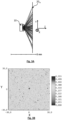
- a tightening of the histogram is observed around small angles, in the transverse plane P YZ . This shows that the invention makes it possible to increase the proportion of rays, emitted by the light source 10, and emerging from the hood in an angular range of ⁇ 30°, or even ⁇ 25° relative to the transverse axis Z.
- the inventors performed modeling by varying the parameters d 2 (length of each peripheral part parallel to the longitudinal axis Y), and ⁇ (angle of inclination of each peripheral part).
- this proportion is 31%.
- THE 3D figures And 3E represent ray tracings by respectively arranging a 10 A light source according to the prior art (cf. Figure 2A ), and a light source 10 according to the configuration shown in the Figure 2C .
- the light source is arranged as shown in the Figures 1A and 1B : It opens into the enclosure 2 of the gas sensor.
- the transverse axis Z of the light source 10 is parallel to the transverse walls, and centered relative to the latter.
- Comparison of the 3D figures And 3E show that the invention makes it possible to increase the quantity of rays emerging from the light source 10 at an angle ⁇ of ⁇ 30° relative to the transverse axis Z.
- the configuration according to the invention helps reduce the proportion of rays passing through these areas.
- the first inclination angle ⁇ 1 and the second inclination angle ⁇ 2 can form the same inclination angle ⁇ .
- FIG. 4A is a perspective view of the second embodiment.
- the Figure 4B is a top view of the second embodiment.
- the lateral and longitudinal axes of the central part and of each peripheral part are represented.
- Such an embodiment may for example be adapted to a gas sensor as described in connection with the Figure 1A , but also to a gas sensor in which the enclosure 2, separating the light source from the photodetector, is cylindrical, around the transverse axis Z.
- FIG. 4D represents a result of the modeling carried out by varying the parameters d 2 (length of each peripheral part parallel to the longitudinal axis Y or to the lateral axis X) and ⁇ (angle of inclination of each peripheral part).
- the ordinate axis corresponds to the variation range of d 2 , (unit: mm) and the abscissa axis corresponds to the variation range of ⁇ (unit: degree).
- the gray level corresponds to a percentage of rays emerging from the cover 14 in an angular range of ⁇ 30° around the transverse axis Z.
- the objective of the modeling is to determine the parameters maximizing this percentage.
- FIG. 4E is a histogram of the angles ⁇ , relative to the transverse axis Z, of the rays detected by the 20 m photodetector.
- the histogram was produced in the same way as those of the Figures 3B And 3C , considering a light source as shown in the Figures 4A to 4C , according to the optimized parameters reported in the previous paragraph.
- the external face 16 of the light source 10 comprises a peripheral portion 16 2 extending, on either side of the central portion, at a first angle of inclination ⁇ 1 over a portion of the length of the peripheral wall 16 2 , then at a second angle of inclination ⁇ 1 ' over another portion of the length of the peripheral wall 16 2 , with ⁇ ' 1 > ⁇ 1 .
- the angles of inclination ⁇ 1 , ⁇ 1 ' correspond to the acute angles between the longitudinal axis Y and the first longitudinal axis Y 1 of each peripheral portion.
- This embodiment corresponds to an improvement of the first embodiment, each peripheral portion successively comprising two angles of inclination.
- FIG. 5B is a histogram of the angles ⁇ , relative to the transverse axis Z, of the rays detected by the 20 m photodetector.
- the histogram was produced in the same way as those of the Figures 3B And 3C , considering a light source as shown in the Figure 5A , according to the optimized parameters reported in the previous paragraph.
- the abscissa and ordinate axes represent respectively the angles, with respect to the Z axis, of the rays detected by the 20 m photodetector, respectively in the P XZ and P YZ planes.
- the center of the Figure 5B marked by a cross, corresponds to rays parallel to the Z axis.
- the gray level represents a number of detected rays.
- a tightening of the histogram is observed around low angles. This shows that the invention makes it possible to increase the proportion of rays, emitted by the light source 10, and emerging from the cover 14 in an angular range of ⁇ 30°, or even ⁇ 20° relative to the transverse Z axis.
- FIG. 5C represents a fourth embodiment according to which the external face 16 comprises two first peripheral parts 16 2,1 and two second peripheral parts 16 2,2 as described in connection with the second embodiment.
- Each first peripheral portion 16 2,1 extends along a first longitudinal axis Y 1 forming, with the longitudinal axis Y, a first acute angle of inclination ⁇ 1 over a portion of the length of the peripheral wall, then along a second acute angle of inclination ⁇ 1 ' over another portion of the length of the peripheral wall, with ⁇ ' 1 > ⁇ 1 .
- Each second peripheral portion 16 2,2 extends along a second lateral axis X 2 forming, with the lateral axis X, the first acute angle of inclination ⁇ 1 over a portion of the length of the peripheral wall, then along the second angle of inclination ⁇ 1 ' over another portion of the length of the peripheral wall, with ⁇ ' 1 > ⁇ 1 .
- FIG. 5D is a histogram of the angles ⁇ , relative to the transverse axis Z, of the rays detected by the 20 m photodetector.
- the histogram was produced in the same way as those of the Figures 3B , 3C , 4E Or 5B ,considering a light source as shown in the Figure 5C , according to the optimized parameters reported in the previous paragraph.
- the abscissa and ordinate axes represent respectively the angles, with respect to the Z axis, of the rays detected by the 20 m photodetector, respectively in the P XZ and P YZ planes.
- the center of the Figure 5D marked by a cross, corresponds to rays parallel to the Z axis.
- the gray level represents a number of rays detected. A tightening of the histogram is observed around low angles. This shows that the invention makes it possible to increase the proportion of rays, emitted by the light source 10, and emerging from the cover 12 in an angular range of ⁇ 30°, or even ⁇ 20° relative to the transverse Z axis.
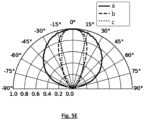
- the abscissa axis corresponds to a standardized luminous intensity.
- the angular range corresponds to the angle ⁇ between the rays emitted by the light source (i.e. emerging from the external face 16) and the transverse axis Z.
- the angular range ⁇ 0.5 for which the standardized luminous intensity is equal to 0.5 was estimated.
- the values of ⁇ 0.5 from curves a, b and c are respectively ⁇ 58°, ⁇ 24°, ⁇ 20°.
- FIGS. 6A and 6B illustrate a variant of the first embodiment, according to which the external face 16 comprises only one peripheral part 16 2 extending around the central part 16 1 .
- FIGs 6C and 6D illustrate a variant of the second embodiment, according to which the external face 16 comprises three peripheral parts: two parts 16 2,1 , and one part referenced 16 2,2 .
- the inventors have modeled the use of a light source according to the first and second embodiments, using the optimized parameters ⁇ , d 2 as described in connection with the figure 4D , on a gas sensor as shown in the Figure 1A .
- the light source 10 is arranged such that the transverse axis Z corresponds to the central axis ⁇ shown in the Figure 1A .
- An amount of light detected by the measuring photodetector 20 and by the reference photodetector 23 was estimated.
- the longitudinal axis Y of the light source 10 is orthogonal to the reflective walls 3 1 and 3 2 .
- Table 1 shows, for the first and second embodiments, a relative increase in the intensity ⁇ I detected by the photodetector and by the reference photodetector, in the absence of absorbing gas in the enclosure.
- Table 1 Method of implementation Measuring photodetector Reference photodetector 1 ( Figure 2G ) 74% 44% 2 ( Figure 4A ) 146% -35%
- the results reported in Table 1 show that the first embodiment makes it possible to increase the quantity of light detected by the measuring photodetector and by the reference photodetector.
- the second embodiment makes it possible to further increase the quantity of light detected by the measuring photodetector (+ 146%), to the detriment of the quantity of light detected by the reference photodetector (- 35%).
- the inventors consider that the first embodiment is particularly suitable for a gas sensor as shown in the Figure 1A .
- the second embodiment appears more suitable for gas sensor configurations having a cylindrical enclosure extending about the transverse axis Z.
- the simulations carried out show that the angle of inclination of a peripheral part, or of each peripheral part, relative to the central part, is preferably between 5° and 30°, and preferably between 5° and 25° or between 5° and 20°.
- FIG. 7 schematizes a method of manufacturing a light source according to the first or second embodiments, cf. Figures 2C , 2G Or 4A .
- the cover 14 may be machined, for example cut, using a cutting tool 41, so as to form a peripheral portion 16 2 inclined relative to the central portion 16 1 .
- the cutting tool comprises a beveled blade 51, making it possible to form the inclination of the peripheral portion 16 2 .
- the cutting tool 41 is translated parallel to the lateral axis X to form the peripheral portions 16 2 .
- the cutting tool 41 is translated parallel to the lateral axis X to form the first peripheral parts 16 2,1 , then parallel to the longitudinal axis Y to form the second peripheral parts 16 2,2 .
- It may be a cutting tool of the type "Dicing blade ZH05 Series - Disco corporation - Japan".
- FIG 8 shows a method of manufacturing a light source according to the third or fourth embodiments, cf. Figure 5A Or 5C .
- the cover 14 can be machined, for example cut, using a first cutting tool 41 and a second cutting tool 42 so as to form a peripheral portion 16 2 inclined relative to the central portion 16 1 , according to two different angles of inclination.
- Each cutting tool comprises a blade 51, 52, arranged to form a peripheral portion inclined successively according to the angles of inclination ⁇ 1 and ⁇ ' 1 .
- the first cutting tool 41 is used, as shown in the figure 7 , then the second cutting tool 42.
- FIG 9 illustrates a deposition of an anti-reflective layer 19 (Anti-reflective coating) on the external face of a light source as described in connection with the first or third embodiment.
- an anti-reflective layer 19 Anti-reflective coating
- the inclination of each peripheral face has little impact on the thickness of the anti-reflective layer 19.
- the thickness on each peripheral part is 0.98 times equal to the thickness of the anti-reflective layer deposited on the central part.
- the performances of the anti-reflective layer 19 can be considered as spatially homogeneous, since the thickness of the latter varies little. This conclusion is valid whatever the embodiment, in particular as long as the angle of inclination ⁇ remains sufficiently small, typically less than 25° and preferably 20°.
- the substrate 12 is also structured.
- the substrate thus comprises a rear external face 12 R , structured in the same way as the external face 16 of the cover 14.
- the objective is to obtain an increase in the radiation emitted by the source and emerging from the substrate 12 with a low incidence relative to the transverse axis Z.
- the light source can be arranged in a gas sensor, the reference photodetector 23 facing the substrate 12.
- FIG. 11A illustrates a manufacturing method, in which the cover 14 comprises a base cover 14 1 and an auxiliary cover 14 2 .
- the base cover 14 1 extends between an inner face 17 and a first face 17 1 .
- the inner face 17 and the first face 17 1 extend parallel to each other.
- the base cover 14 1 is assembled on a substrate 12, the base cover and the substrate enclosing a cavity 15 comprising an emission element 11, for example a membrane.
- the emission element extends along a radial plane around a center 11 c .
- the auxiliary cover 14 2 extends between a second face 17 2 and an external face 16.
- the latter is structured, around a center 16 c , as described in connection with the previous embodiments.
- the auxiliary cover 14 2 is then assembled to the base cover 14 1 , such that the first face 17 1 is arranged against the second face 17 2 .
- the assembly is carried out such that the center 11 c of the emission element 11 is aligned with the center 16 c of the external face, parallel to the transverse axis Z.
- the alignment is materialized by a mixed line.
- the base cover 14 1 and the auxiliary cover 14 2 may be formed of the same material, for example silicon.
- the auxiliary cover 14 2 may be formed of a different material than the base cover 14 1 .
- the auxiliary cover 14 2 may for example be made of glass, while the base cover is made of silicon.
- the assembly of the auxiliary cover 14 2 on the base cover 14 1 forms a cover 14 of the light source 10.
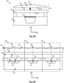
- FIG. 11B illustrates a method of collectively manufacturing a plurality of light sources according to the embodiment similar to that described in connection with the Figure 11A .
- a base cover 14 1 and an auxiliary cover 14 2 are available.
- the base cover 14 1 extends between an inner face 17 and a first face 17 1 .
- the inner face 17 and the first face 17 1 extend parallel to each other.
- the base cover 14 1 is assembled on a substrate 12, the base cover and the substrate contain a plurality of cavities 15, each cavity 15 comprising an emission element 11, for example a membrane.
- Each emission element 11 extends along a radial plane around a center 11 c .
- the assembly formed by the base cover, the substrate 12, the cavity 15 and the membrane 11 corresponds to a basic light source.
- the auxiliary cover 14 2 extends between a second face 17 2 and an external face 16.
- the latter is the subject of a structuring, around centers 16 c , distinct from each other.
- the structuring comprises the production of at least one peripheral part 16 2 inclined relative to central parts, parallel to the second face 17 2 , each central part passing respectively through each center 16 c .
- the auxiliary cover 14 2 is then assembled to the base cover 14 1 , such that the first face 17 1 is arranged against the second face 17 2 .
- the assembly is carried out such that each center 11 c of an emission element is aligned with a center 16 c of the external face 16, parallel to the transverse axis Z.
- the alignment is materialized by a mixed line.
- each light source 10 is represented by a dotted frame.
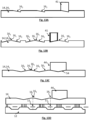
- each basic light source is formed by an emission element 11 (in particular a membrane), extending along a radial plane, in a cavity 15 delimited by a cover 14 A and a substrate 12.
- the cover 14 A extends between two parallel faces.
- the Figures 12B and 12C represent a separation of each basic light source 10 A , by a cutout of the cover 14 A (cf. Figure 12B ) then the substrate ( figure 12C ).
- On the figure 12C we have materialized, by a dotted frame, a 10 A light source thus obtained.
- the structuring is carried out by implementing a cutting tool 41, as described in connection with FIG. 7A. This makes it possible to provide, on the same external face, different peripheral parts 16 2 extending respectively around different central parts 16 1 .
- the structuring is carried out by using a tool 44, comprising a V-shaped blade 54. This makes it possible to simultaneously form two peripheral parts 16 2 on the external face.
- the figure 13D shows the application of a cutting tool 44 to a substrate 14, which initially has a shape corresponding to the substrate 14A shown in the Figure 12A .
- FIGS. 14A and 14B show a result of the application of collective manufacturing processes of light sources 10.
- the collective manufacturing processes are those described in connection with the Figure 11B , Or 13A to 13D .
- On the Figure 14A we have represented a manufacture of sources of light according to the first embodiment.
- On the Figure 14B a production of light sources according to the second embodiment is shown.
- the light sources according to the invention may be used in gas sensors, the latter applied to different fields, for example the environment, in particular the control of atmospheric pollution, industry, for example the chemical, oil or agri-food industry, or health.
Landscapes
- Physics & Mathematics (AREA)
- Spectroscopy & Molecular Physics (AREA)
- General Physics & Mathematics (AREA)
- Health & Medical Sciences (AREA)
- Life Sciences & Earth Sciences (AREA)
- Chemical & Material Sciences (AREA)
- Analytical Chemistry (AREA)
- Biochemistry (AREA)
- General Health & Medical Sciences (AREA)
- Immunology (AREA)
- Pathology (AREA)
- Investigating Or Analysing Materials By Optical Means (AREA)
Claims (15)
- Infrarotlichtquelle (10), aufweisend:- ein Emissionselement (11), das sich in einer radialen Ebene (PXY) um eine Mitte des Emissionselements (11c) erstreckt, wobei das Emissionselement zur Erwärmung ausgestaltet ist, wobei die Erwärmung zu einer Emission von Infrarotlicht führt,- einen Hohlraum (15), in dem sich das Emissionselement erstreckt, wobei der Hohlraum durch eine zu dem Emissionselement (11) hingewandte Abdeckung (14) begrenzt ist, wobei die Abdeckung eine Innenfläche (17), die dem Emissionselement (11) gegenüber angeordnet ist, und eine Außenfläche (16), die eine Schnittstelle zwischen der Abdeckung (14) und einer außerhalb der Lichtquelle liegenden Umgebung definiert, aufweist,- wobei sich die Abdeckung parallel zu einer Querachse (Z) senkrecht zu der radialen Ebene (PXY) gemäß einer Dicke (e) zwischen der Innenfläche (17) und der Außenfläche (16) erstreckt,- wobei die Außenfläche Folgendes aufweist:• einen flachen mittleren Teil (161), der sich um eine Mitte (16c) der Außenfläche erstreckt, wobei die Mitte der Außenfläche auf die Mitte des Emissionselements (11c) entlang der Querachse (Z) ausgerichtet ist,wobei die Lichtquelle dadurch gekennzeichnet ist, dass die Außenfläche Folgendes aufweist:• mindestens einen Umfangsteil (162, 162,1, 162,2) neben dem mittleren Teil, wobei der Umfangsteil bezüglich des mittleren Teils in einem Neigungswinkel (θ) geneigt ist,- so dass die Dicke (e) der Abdeckung (14) in dem Umfangsteil in Abhängigkeit von einem Abstand von dem mittleren Teil (161) abnimmt.
- Lichtquelle nach Anspruch 1, wobei sich der Umfangsteil (162, 162,1, 162,2) beiderseits des mittleren Teils (161) erstreckt.
- Lichtquelle nach einem der vorhergehenden Ansprüche, wobei der Umfangsteil (162, 162,1, 162,2) bezüglich des mittleren Teils (161) in einem Neigungswinkel zwischen 5° und 30° und vorzugsweise zwischen 5° und 20° geneigt ist.
- Lichtquelle nach einem der vorhergehenden Ansprüche, wobei:- sich der mittlere Teil (161) parallel zu einer Längsachse (Y) und einer Querachse (X) erstreckt, wobei die Längsachse senkrecht zu der Querachse verläuft,- sich der Umfangsteil (162,162,1) parallel zu einer ersten Längsachse (Y1) und zu einer ersten Querachse (X1) erstreckt,- die erste Längsachse (Y1) in dem Neigungswinkel (θ) zu der Längsachse (Y) geneigt ist,- die erste Querachse (X1) parallel zu der Querachse (X) verläuft.
- Lichtquelle nach Anspruch 4, aufweisend einen zweiten Umfangsteil (162,2) neben dem mittleren Teil, so dass:- sich der zweite Umfangsteil parallel zu einer zweiten Längsachse (Y2) und einer zweiten Querachse (X2) erstreckt,- die zweite Querachse (X2) in einem zweiten Neigungswinkel (θ2) zu der Querachse (X) geneigt ist,- die zweite Längsachse (Y2) parallel zu der Längsachse (Y) verläuft.
- Lichtquelle nach einem der vorhergehenden Ansprüche, wobei sich der Umfangsteil (162) entlang einer Länge zwischen 5% und 50% einer Länge der Abdeckung (14) erstreckt, wobei die Länge parallel zu der Querachse oder zu der Längsachse bestimmt wird.
- Lichtquelle nach einem der vorhergehenden Ansprüche, wobei mindestens ein Umfangsteil in verschiedenen Neigungswinkeln (θ1, θ'1) zu dem mittleren Teil geneigt ist, wobei sich die Neigungswinkel mit dem Abstand von dem mittleren Teil (161) vergrößern.
- Lichtquelle nach einem der vorhergehenden Ansprüche, wobei der mittlere Teil (16) bezüglich des Emissionselements (11) entlang der Querachse (Z) zentriert ist.
- Lichtquelle nach einem der vorhergehenden Ansprüche, wobei sich die Außenfläche (16) entlang einer parallel zu der radialen Ebene (PXY) verlaufenden Achse in einer Länge zwischen 500 µm und 2500 µm erstreckt.
- Gassensor (1), aufweisend ein Gehäuse (2), das für die Aufnahme eines Gases ausgestaltet ist, sowie eine Lichtquelle (10) und mindestens einen Fotodetektor (20), wobei die Lichtquelle zur Emittierung einer Lichtstrahlung ausgestaltet ist, die sich durch das Gehäuse zu dem Fotodetektor ausbreitet, wobei die Lichtquelle eine Lichtquelle nach einem der Ansprüche 1 bis 9 ist.
- Gassensor nach Anspruch 10, wobei das Gehäuse (2) durch mindestens eine erste Reflektorwand (31) begrenzt ist, die sich senkrecht zu der radialen Ebene (PXY) der Lichtquelle parallel zu der Querachse (Z) erstreckt.
- Gassensor nach Anspruch 11, wobei die Außenfläche (16) der Abdeckung (14) der Lichtquelle (10) einen flachen mittleren Teil (161) aufweist, der sich in einer parallel zu der radialen Ebene verlaufenden Ebene erstreckt und durch die Mitte der Außenfläche (16c) geht, und wobei:- sich der mittlere Teil (161) parallel zu einer Längsachse (Y) und einer Querachse (X) erstreckt, wobei die Längsachse senkrecht zu der Querachse verläuft,- sich der Umfangsteil (162) parallel zu einer ersten Längsachse (Y1) und zu einer ersten Querachse (X1) erstreckt,- die erste Längsachse (Y1) in einem Neigungswinkel (θ) zu der Längsachse (Y) geneigt ist,- die erste Querachse (X1) parallel zu der Querachse (X) verläuft,wobei die Lichtquelle so angeordnet ist, dass die Längsachse (Y) senkrecht zu der ersten Reflektorwand verläuft.
- Gassensor nach einem der Ansprüche 10 bis 12, wobei das Gehäuse durch eine zweite Reflektorwand (32) begrenzt ist, die sich parallel zu der ersten Reflektorwand erstreckt, wobei sich die Lichtquelle zwischen der ersten und der zweiten Reflektorwand erstreckt.
- Gassensor nach Anspruch 13, wobei die Mitte des Emissionselements (11c) der Lichtquelle (10) äquidistant von jeder Reflektorwand angeordnet ist.
- Verfahren zur Herstellung einer Infrarotlichtquelle nach einem der Ansprüche 1 bis 9, aufweisend:- a) Erhalten einer Lichtquelle, wobei die Lichtquelle ein Emissionselement (11) umfasst, das sich parallel zu einer radialen Ebene (PXY) um eine Mitte des Emissionselements (11c) erstreckt, wobei das Emissionselement so ausgestaltet ist, dass es sich erhitzt, wobei das Erhitzen zu einer Infrarotlichtemission führt, und in einem Hohlraum (15) angeordnet ist, der durch eine Abdeckung begrenzt ist, wobei sich die Abdeckung zwischen einer dem Emissionselement zugewandten Innenfläche (17) und einer Außenfläche (16) erstreckt, wobei sich die Außenfläche parallel zu der radialen Ebene (PXY) um eine Mitte (16c) der Außenfläche erstreckt, wobei die Mitte der Außenfläche auf die Mitte des Emissionselements (11c) entlang einer Querachse (Z) senkrecht zu der radialen Ebene ausgerichtet ist, wobei der Abstand zwischen der Innenfläche und der Außenfläche eine Dicke (e) der Abdeckung definiert,- b) Bearbeiten der Außenfläche (16), um in der Außenfläche mindestens einen Umfangsteil (162, 162,1, 162,2) neben einem flachen mittleren Teil (161) der Außenfläche auszubilden, der durch die Mitte der Außenfläche (16c) geht und parallel zu der radialen Ebene verläuft, wobei der Umfangsteil so zu dem mittleren Teil geneigt ist, dass in dem Umfangsteil die Dicke der Abdeckung in Abhängigkeit von einem Abstand von der Mitte der Außenfläche abnimmt.
Applications Claiming Priority (2)
| Application Number | Priority Date | Filing Date | Title |
|---|---|---|---|
| FR2010377A FR3115104B1 (fr) | 2020-10-10 | 2020-10-10 | Dispositif d'émission de lumière optimisé pour capteur de gaz , et procédé de fabrication |
| PCT/EP2021/077795 WO2022074169A1 (fr) | 2020-10-10 | 2021-10-07 | Source de lumière infrarouge optimisée pour capteur de gaz, et son procédé de fabrication |
Publications (2)
| Publication Number | Publication Date |
|---|---|
| EP4226143A1 EP4226143A1 (de) | 2023-08-16 |
| EP4226143B1 true EP4226143B1 (de) | 2025-01-01 |
Family
ID=75539373
Family Applications (1)
| Application Number | Title | Priority Date | Filing Date |
|---|---|---|---|
| EP21790140.4A Active EP4226143B1 (de) | 2020-10-10 | 2021-10-07 | Für gassensoren optimierte infrarot-lichtquelle und verfahren zu ihrer herstellung |
Country Status (4)
| Country | Link |
|---|---|
| US (1) | US12372457B2 (de) |
| EP (1) | EP4226143B1 (de) |
| FR (1) | FR3115104B1 (de) |
| WO (1) | WO2022074169A1 (de) |
Family Cites Families (9)
| Publication number | Priority date | Publication date | Assignee | Title |
|---|---|---|---|---|
| US5026992A (en) | 1989-09-06 | 1991-06-25 | Gaztech Corporation | Spectral ratioing technique for NDIR gas analysis using a differential temperature source |
| US5285131A (en) * | 1990-12-03 | 1994-02-08 | University Of California - Berkeley | Vacuum-sealed silicon incandescent light |
| DE102004032176A1 (de) * | 2004-07-02 | 2006-01-26 | Robert Bosch Gmbh | Beschichteter mikromechanischer Strahler |
| WO2007064370A2 (en) | 2005-08-04 | 2007-06-07 | Airware Inc. | Ultra low cost ndir gas sensors |
| US9297749B2 (en) * | 2012-03-27 | 2016-03-29 | Innovative Science Tools, Inc. | Optical analyzer for identification of materials using transmission spectroscopy |
| FR3016213B1 (fr) * | 2014-01-06 | 2016-02-26 | Commissariat Energie Atomique | Capteur de gaz miniature. |
| FR3048084A1 (fr) * | 2016-02-18 | 2017-08-25 | Commissariat Energie Atomique | Capteur infrarouge non-dispersif pour detecter un gaz. |
| FR3063811B1 (fr) | 2017-03-10 | 2021-08-27 | Elichens | Capteur optique de gaz |
| FR3072775B1 (fr) | 2017-10-23 | 2019-09-27 | Elichens | Detecteur de gaz compact |
-
2020
- 2020-10-10 FR FR2010377A patent/FR3115104B1/fr active Active
-
2021
- 2021-10-07 WO PCT/EP2021/077795 patent/WO2022074169A1/fr not_active Ceased
- 2021-10-07 US US18/248,358 patent/US12372457B2/en active Active
- 2021-10-07 EP EP21790140.4A patent/EP4226143B1/de active Active
Also Published As
| Publication number | Publication date |
|---|---|
| US20230296499A1 (en) | 2023-09-21 |
| US12372457B2 (en) | 2025-07-29 |
| FR3115104B1 (fr) | 2022-09-30 |
| WO2022074169A1 (fr) | 2022-04-14 |
| FR3115104A1 (fr) | 2022-04-15 |
| EP4226143A1 (de) | 2023-08-16 |
Similar Documents
| Publication | Publication Date | Title |
|---|---|---|
| EP3593119B1 (de) | Optischer gassensor | |
| EP3208601B1 (de) | Nicht-dispersiver infrarotsensor zur detektion eines gases | |
| EP3563140B1 (de) | Vorrichtung zur detektion von gas oder partikeln und verfahren zur herstellung einer solchen vorrichtung | |
| EP0015170B1 (de) | Spektrofotometrische Vorrichtung mit Fernmessung | |
| EP0655221A1 (de) | Kolorimetrischer Messkopf und Verfahren zur Farbbestimmung des Inneren eines lichtdurchlässigen Materials | |
| EP3436807B1 (de) | Verfahren und system zur inspektion von platten für die mikroelektronik oder optik durch laser-doppler-effekt | |
| EP4019943B1 (de) | Fotoakustische detektionsvorrichtung mit einer schutzmembran | |
| WO2018138223A1 (fr) | Détecteur optique de particules | |
| EP3959506B1 (de) | Kompakter gassensor | |
| EP3701247B1 (de) | Kompakter gassensor | |
| EP4226143B1 (de) | Für gassensoren optimierte infrarot-lichtquelle und verfahren zu ihrer herstellung | |
| FR2941529A1 (fr) | Unite d'excitation lumineuse d'un echantillon et de collection de la lumiere emise par ledit echantillon excite | |
| FR3096461A1 (fr) | Dispositif d'émission et de contrôle d'une lumière infra-rouge et capteur de gaz utilisant un tel dispositif | |
| EP2368104B1 (de) | Mit emissionsquellenüberwachung versehene optische absorptionssonde | |
| EP0670993B1 (de) | Verfahren und vorrichtung zum messen der temperatur eines objektes, besonders eines halbleiters, mittels ellipsometrie | |
| EP3583402B1 (de) | Optischer partikeldetektor und verfahren zur herstellung eines optischen partikeldetektor | |
| EP1853898B1 (de) | Verfahren und system zur physikochemischen analyse mittels lasergepulster ablation | |
| EP3431964B1 (de) | Optischer hohlraum mit starker dynamik | |
| EP2887052A1 (de) | Verfahren und Vorrichtung zur Vorbereitung und optischen Analyse einer festen Probe, die einem kontrollierten Umfeld ausgesetzt wird, durch Infrarot-Spektroskopie mit mehrfachen internen Reflexionen | |
| EP2565623A1 (de) | Vorrichtung zur optischen Messung von Materialien anhand eines Multiplexverfahrens von Licht | |
| EP4407300B1 (de) | Kompakter gassensor mit einfachem design | |
| EP1516218A2 (de) | Einrichtung zum automatischen zentrieren eines laserstrahls und verfahren zu ihrer herstellung | |
| WO2020053515A1 (fr) | Capteur de gaz compact | |
| EP4345446B1 (de) | Multispektrale reflexionsbildgebungsvorrichtung | |
| FR2807517A1 (fr) | Cellule optique multipassages par spectroscopie d'absorption, appareil de mise en oeuvre et procede de realisation |
Legal Events
| Date | Code | Title | Description |
|---|---|---|---|
| STAA | Information on the status of an ep patent application or granted ep patent |
Free format text: STATUS: UNKNOWN |
|
| STAA | Information on the status of an ep patent application or granted ep patent |
Free format text: STATUS: THE INTERNATIONAL PUBLICATION HAS BEEN MADE |
|
| PUAI | Public reference made under article 153(3) epc to a published international application that has entered the european phase |
Free format text: ORIGINAL CODE: 0009012 |
|
| STAA | Information on the status of an ep patent application or granted ep patent |
Free format text: STATUS: REQUEST FOR EXAMINATION WAS MADE |
|
| 17P | Request for examination filed |
Effective date: 20230410 |
|
| AK | Designated contracting states |
Kind code of ref document: A1 Designated state(s): AL AT BE BG CH CY CZ DE DK EE ES FI FR GB GR HR HU IE IS IT LI LT LU LV MC MK MT NL NO PL PT RO RS SE SI SK SM TR |
|
| DAV | Request for validation of the european patent (deleted) | ||
| DAX | Request for extension of the european patent (deleted) | ||
| GRAP | Despatch of communication of intention to grant a patent |
Free format text: ORIGINAL CODE: EPIDOSNIGR1 |
|
| STAA | Information on the status of an ep patent application or granted ep patent |
Free format text: STATUS: GRANT OF PATENT IS INTENDED |
|
| RIC1 | Information provided on ipc code assigned before grant |
Ipc: H01K 7/02 20060101ALI20240715BHEP Ipc: H01K 1/14 20060101ALI20240715BHEP Ipc: G01J 3/42 20060101ALI20240715BHEP Ipc: G01J 3/10 20060101ALI20240715BHEP Ipc: G01J 3/02 20060101ALI20240715BHEP Ipc: G01N 21/3504 20140101ALI20240715BHEP Ipc: G01N 21/03 20060101AFI20240715BHEP |
|
| INTG | Intention to grant announced |
Effective date: 20240726 |
|
| GRAS | Grant fee paid |
Free format text: ORIGINAL CODE: EPIDOSNIGR3 |
|
| GRAA | (expected) grant |
Free format text: ORIGINAL CODE: 0009210 |
|
| STAA | Information on the status of an ep patent application or granted ep patent |
Free format text: STATUS: THE PATENT HAS BEEN GRANTED |
|
| AK | Designated contracting states |
Kind code of ref document: B1 Designated state(s): AL AT BE BG CH CY CZ DE DK EE ES FI FR GB GR HR HU IE IS IT LI LT LU LV MC MK MT NL NO PL PT RO RS SE SI SK SM TR |
|
| REG | Reference to a national code |
Ref country code: GB Ref legal event code: FG4D Free format text: NOT ENGLISH |
|
| REG | Reference to a national code |
Ref country code: CH Ref legal event code: EP |
|
| REG | Reference to a national code |
Ref country code: DE Ref legal event code: R096 Ref document number: 602021024330 Country of ref document: DE |
|
| REG | Reference to a national code |
Ref country code: IE Ref legal event code: FG4D Free format text: LANGUAGE OF EP DOCUMENT: FRENCH |
|
| REG | Reference to a national code |
Ref country code: LT Ref legal event code: MG9D |
|
| REG | Reference to a national code |
Ref country code: NL Ref legal event code: MP Effective date: 20250101 |
|
| REG | Reference to a national code |
Ref country code: AT Ref legal event code: MK05 Ref document number: 1756695 Country of ref document: AT Kind code of ref document: T Effective date: 20250101 |
|
| PG25 | Lapsed in a contracting state [announced via postgrant information from national office to epo] |
Ref country code: NL Free format text: LAPSE BECAUSE OF FAILURE TO SUBMIT A TRANSLATION OF THE DESCRIPTION OR TO PAY THE FEE WITHIN THE PRESCRIBED TIME-LIMIT Effective date: 20250101 |
|
| PG25 | Lapsed in a contracting state [announced via postgrant information from national office to epo] |
Ref country code: FI Free format text: LAPSE BECAUSE OF FAILURE TO SUBMIT A TRANSLATION OF THE DESCRIPTION OR TO PAY THE FEE WITHIN THE PRESCRIBED TIME-LIMIT Effective date: 20250101 |
|
| PG25 | Lapsed in a contracting state [announced via postgrant information from national office to epo] |
Ref country code: PL Free format text: LAPSE BECAUSE OF FAILURE TO SUBMIT A TRANSLATION OF THE DESCRIPTION OR TO PAY THE FEE WITHIN THE PRESCRIBED TIME-LIMIT Effective date: 20250101 |
|
| PG25 | Lapsed in a contracting state [announced via postgrant information from national office to epo] |
Ref country code: ES Free format text: LAPSE BECAUSE OF FAILURE TO SUBMIT A TRANSLATION OF THE DESCRIPTION OR TO PAY THE FEE WITHIN THE PRESCRIBED TIME-LIMIT Effective date: 20250101 |
|
| PG25 | Lapsed in a contracting state [announced via postgrant information from national office to epo] |
Ref country code: NO Free format text: LAPSE BECAUSE OF FAILURE TO SUBMIT A TRANSLATION OF THE DESCRIPTION OR TO PAY THE FEE WITHIN THE PRESCRIBED TIME-LIMIT Effective date: 20250401 Ref country code: IS Free format text: LAPSE BECAUSE OF FAILURE TO SUBMIT A TRANSLATION OF THE DESCRIPTION OR TO PAY THE FEE WITHIN THE PRESCRIBED TIME-LIMIT Effective date: 20250501 |
|
| PG25 | Lapsed in a contracting state [announced via postgrant information from national office to epo] |
Ref country code: HR Free format text: LAPSE BECAUSE OF FAILURE TO SUBMIT A TRANSLATION OF THE DESCRIPTION OR TO PAY THE FEE WITHIN THE PRESCRIBED TIME-LIMIT Effective date: 20250101 |
|
| PG25 | Lapsed in a contracting state [announced via postgrant information from national office to epo] |
Ref country code: LV Free format text: LAPSE BECAUSE OF FAILURE TO SUBMIT A TRANSLATION OF THE DESCRIPTION OR TO PAY THE FEE WITHIN THE PRESCRIBED TIME-LIMIT Effective date: 20250101 Ref country code: PT Free format text: LAPSE BECAUSE OF FAILURE TO SUBMIT A TRANSLATION OF THE DESCRIPTION OR TO PAY THE FEE WITHIN THE PRESCRIBED TIME-LIMIT Effective date: 20250502 |
|
| PG25 | Lapsed in a contracting state [announced via postgrant information from national office to epo] |
Ref country code: BG Free format text: LAPSE BECAUSE OF FAILURE TO SUBMIT A TRANSLATION OF THE DESCRIPTION OR TO PAY THE FEE WITHIN THE PRESCRIBED TIME-LIMIT Effective date: 20250101 Ref country code: GR Free format text: LAPSE BECAUSE OF FAILURE TO SUBMIT A TRANSLATION OF THE DESCRIPTION OR TO PAY THE FEE WITHIN THE PRESCRIBED TIME-LIMIT Effective date: 20250402 |
|
| PG25 | Lapsed in a contracting state [announced via postgrant information from national office to epo] |
Ref country code: AT Free format text: LAPSE BECAUSE OF FAILURE TO SUBMIT A TRANSLATION OF THE DESCRIPTION OR TO PAY THE FEE WITHIN THE PRESCRIBED TIME-LIMIT Effective date: 20250101 |
|
| PG25 | Lapsed in a contracting state [announced via postgrant information from national office to epo] |
Ref country code: CZ Free format text: LAPSE BECAUSE OF FAILURE TO SUBMIT A TRANSLATION OF THE DESCRIPTION OR TO PAY THE FEE WITHIN THE PRESCRIBED TIME-LIMIT Effective date: 20250101 |
|
| PG25 | Lapsed in a contracting state [announced via postgrant information from national office to epo] |
Ref country code: SE Free format text: LAPSE BECAUSE OF FAILURE TO SUBMIT A TRANSLATION OF THE DESCRIPTION OR TO PAY THE FEE WITHIN THE PRESCRIBED TIME-LIMIT Effective date: 20250101 |
|
| REG | Reference to a national code |
Ref country code: DE Ref legal event code: R097 Ref document number: 602021024330 Country of ref document: DE |
|
| PG25 | Lapsed in a contracting state [announced via postgrant information from national office to epo] |
Ref country code: SM Free format text: LAPSE BECAUSE OF FAILURE TO SUBMIT A TRANSLATION OF THE DESCRIPTION OR TO PAY THE FEE WITHIN THE PRESCRIBED TIME-LIMIT Effective date: 20250101 |
|
| PG25 | Lapsed in a contracting state [announced via postgrant information from national office to epo] |
Ref country code: DK Free format text: LAPSE BECAUSE OF FAILURE TO SUBMIT A TRANSLATION OF THE DESCRIPTION OR TO PAY THE FEE WITHIN THE PRESCRIBED TIME-LIMIT Effective date: 20250101 |
|
| PG25 | Lapsed in a contracting state [announced via postgrant information from national office to epo] |
Ref country code: IT Free format text: LAPSE BECAUSE OF FAILURE TO SUBMIT A TRANSLATION OF THE DESCRIPTION OR TO PAY THE FEE WITHIN THE PRESCRIBED TIME-LIMIT Effective date: 20250101 |
|
| PG25 | Lapsed in a contracting state [announced via postgrant information from national office to epo] |
Ref country code: EE Free format text: LAPSE BECAUSE OF FAILURE TO SUBMIT A TRANSLATION OF THE DESCRIPTION OR TO PAY THE FEE WITHIN THE PRESCRIBED TIME-LIMIT Effective date: 20250101 |
|
| PG25 | Lapsed in a contracting state [announced via postgrant information from national office to epo] |
Ref country code: RO Free format text: LAPSE BECAUSE OF FAILURE TO SUBMIT A TRANSLATION OF THE DESCRIPTION OR TO PAY THE FEE WITHIN THE PRESCRIBED TIME-LIMIT Effective date: 20250101 |
|
| PG25 | Lapsed in a contracting state [announced via postgrant information from national office to epo] |
Ref country code: SK Free format text: LAPSE BECAUSE OF FAILURE TO SUBMIT A TRANSLATION OF THE DESCRIPTION OR TO PAY THE FEE WITHIN THE PRESCRIBED TIME-LIMIT Effective date: 20250101 |
|
| PLBE | No opposition filed within time limit |
Free format text: ORIGINAL CODE: 0009261 |
|
| STAA | Information on the status of an ep patent application or granted ep patent |
Free format text: STATUS: NO OPPOSITION FILED WITHIN TIME LIMIT |
|
| 26N | No opposition filed |
Effective date: 20251002 |
|
| PGFP | Annual fee paid to national office [announced via postgrant information from national office to epo] |
Ref country code: DE Payment date: 20251030 Year of fee payment: 5 |
|
| PGFP | Annual fee paid to national office [announced via postgrant information from national office to epo] |
Ref country code: GB Payment date: 20251024 Year of fee payment: 5 |
|
| PGFP | Annual fee paid to national office [announced via postgrant information from national office to epo] |
Ref country code: FR Payment date: 20251024 Year of fee payment: 5 |