EP4227005A1 - Überlastsicherung für das hydraulische system einer mineralmaterial-bearbeitungsanlage - Google Patents
Überlastsicherung für das hydraulische system einer mineralmaterial-bearbeitungsanlage Download PDFInfo
- Publication number
- EP4227005A1 EP4227005A1 EP23152225.1A EP23152225A EP4227005A1 EP 4227005 A1 EP4227005 A1 EP 4227005A1 EP 23152225 A EP23152225 A EP 23152225A EP 4227005 A1 EP4227005 A1 EP 4227005A1
- Authority
- EP
- European Patent Office
- Prior art keywords
- bursting
- connection area
- hydraulic
- holder
- overload protection
- Prior art date
- Legal status (The legal status is an assumption and is not a legal conclusion. Google has not performed a legal analysis and makes no representation as to the accuracy of the status listed.)
- Granted
Links
Images


Classifications
-
- B—PERFORMING OPERATIONS; TRANSPORTING
- B02—CRUSHING, PULVERISING, OR DISINTEGRATING; PREPARATORY TREATMENT OF GRAIN FOR MILLING
- B02C—CRUSHING, PULVERISING, OR DISINTEGRATING IN GENERAL; MILLING GRAIN
- B02C21/00—Disintegrating plant with or without drying of the material
- B02C21/02—Transportable disintegrating plant
- B02C21/026—Transportable disintegrating plant self-propelled
-
- B—PERFORMING OPERATIONS; TRANSPORTING
- B02—CRUSHING, PULVERISING, OR DISINTEGRATING; PREPARATORY TREATMENT OF GRAIN FOR MILLING
- B02C—CRUSHING, PULVERISING, OR DISINTEGRATING IN GENERAL; MILLING GRAIN
- B02C1/00—Crushing or disintegrating by reciprocating members
- B02C1/02—Jaw crushers or pulverisers
- B02C1/025—Jaw clearance or overload control
-
- B—PERFORMING OPERATIONS; TRANSPORTING
- B02—CRUSHING, PULVERISING, OR DISINTEGRATING; PREPARATORY TREATMENT OF GRAIN FOR MILLING
- B02C—CRUSHING, PULVERISING, OR DISINTEGRATING IN GENERAL; MILLING GRAIN
- B02C1/00—Crushing or disintegrating by reciprocating members
- B02C1/02—Jaw crushers or pulverisers
- B02C1/08—Jaw crushers or pulverisers with jaws coacting with rotating roller
-
- B—PERFORMING OPERATIONS; TRANSPORTING
- B02—CRUSHING, PULVERISING, OR DISINTEGRATING; PREPARATORY TREATMENT OF GRAIN FOR MILLING
- B02C—CRUSHING, PULVERISING, OR DISINTEGRATING IN GENERAL; MILLING GRAIN
- B02C13/00—Disintegrating by mills having rotary beater elements ; Hammer mills
- B02C13/02—Disintegrating by mills having rotary beater elements ; Hammer mills with horizontal rotor shaft
- B02C13/06—Disintegrating by mills having rotary beater elements ; Hammer mills with horizontal rotor shaft with beaters rigidly connected to the rotor
- B02C13/09—Disintegrating by mills having rotary beater elements ; Hammer mills with horizontal rotor shaft with beaters rigidly connected to the rotor and throwing the material against an anvil or impact plate
- B02C13/095—Disintegrating by mills having rotary beater elements ; Hammer mills with horizontal rotor shaft with beaters rigidly connected to the rotor and throwing the material against an anvil or impact plate with an adjustable anvil or impact plate
-
- B—PERFORMING OPERATIONS; TRANSPORTING
- B02—CRUSHING, PULVERISING, OR DISINTEGRATING; PREPARATORY TREATMENT OF GRAIN FOR MILLING
- B02C—CRUSHING, PULVERISING, OR DISINTEGRATING IN GENERAL; MILLING GRAIN
- B02C13/00—Disintegrating by mills having rotary beater elements ; Hammer mills
- B02C13/26—Details
- B02C13/31—Safety devices or measures
-
- B—PERFORMING OPERATIONS; TRANSPORTING
- B02—CRUSHING, PULVERISING, OR DISINTEGRATING; PREPARATORY TREATMENT OF GRAIN FOR MILLING
- B02C—CRUSHING, PULVERISING, OR DISINTEGRATING IN GENERAL; MILLING GRAIN
- B02C23/00—Auxiliary methods or auxiliary devices or accessories specially adapted for crushing or disintegrating not provided for in preceding groups or not specially adapted to apparatus covered by a single preceding group
- B02C23/04—Safety devices
-
- B—PERFORMING OPERATIONS; TRANSPORTING
- B02—CRUSHING, PULVERISING, OR DISINTEGRATING; PREPARATORY TREATMENT OF GRAIN FOR MILLING
- B02C—CRUSHING, PULVERISING, OR DISINTEGRATING IN GENERAL; MILLING GRAIN
- B02C23/00—Auxiliary methods or auxiliary devices or accessories specially adapted for crushing or disintegrating not provided for in preceding groups or not specially adapted to apparatus covered by a single preceding group
- B02C23/08—Separating or sorting of material, associated with crushing or disintegrating
- B02C23/10—Separating or sorting of material, associated with crushing or disintegrating with separator arranged in discharge path of crushing or disintegrating zone
- B02C23/12—Separating or sorting of material, associated with crushing or disintegrating with separator arranged in discharge path of crushing or disintegrating zone with return of oversize material to crushing or disintegrating zone
-
- F—MECHANICAL ENGINEERING; LIGHTING; HEATING; WEAPONS; BLASTING
- F16—ENGINEERING ELEMENTS AND UNITS; GENERAL MEASURES FOR PRODUCING AND MAINTAINING EFFECTIVE FUNCTIONING OF MACHINES OR INSTALLATIONS; THERMAL INSULATION IN GENERAL
- F16K—VALVES; TAPS; COCKS; ACTUATING-FLOATS; DEVICES FOR VENTING OR AERATING
- F16K17/00—Safety valves; Equalising valves, e.g. pressure relief valves
- F16K17/02—Safety valves; Equalising valves, e.g. pressure relief valves opening on surplus pressure on one side; closing on insufficient pressure on one side
- F16K17/14—Safety valves; Equalising valves, e.g. pressure relief valves opening on surplus pressure on one side; closing on insufficient pressure on one side with fracturing member
- F16K17/16—Safety valves; Equalising valves, e.g. pressure relief valves opening on surplus pressure on one side; closing on insufficient pressure on one side with fracturing member with fracturing diaphragm ; Rupture discs
-
- F—MECHANICAL ENGINEERING; LIGHTING; HEATING; WEAPONS; BLASTING
- F16—ENGINEERING ELEMENTS AND UNITS; GENERAL MEASURES FOR PRODUCING AND MAINTAINING EFFECTIVE FUNCTIONING OF MACHINES OR INSTALLATIONS; THERMAL INSULATION IN GENERAL
- F16K—VALVES; TAPS; COCKS; ACTUATING-FLOATS; DEVICES FOR VENTING OR AERATING
- F16K17/00—Safety valves; Equalising valves, e.g. pressure relief valves
- F16K17/40—Safety valves; Equalising valves, e.g. pressure relief valves with a fracturing member, e.g. fracturing diaphragm, glass, fusible joint
-
- F—MECHANICAL ENGINEERING; LIGHTING; HEATING; WEAPONS; BLASTING
- F16—ENGINEERING ELEMENTS AND UNITS; GENERAL MEASURES FOR PRODUCING AND MAINTAINING EFFECTIVE FUNCTIONING OF MACHINES OR INSTALLATIONS; THERMAL INSULATION IN GENERAL
- F16P—SAFETY DEVICES IN GENERAL; SAFETY DEVICES FOR PRESSES
- F16P5/00—Emergency means for rendering ineffective a coupling conveying reciprocating movement if the motion of the driven part is prematurely resisted
- F16P5/005—Overload protection by energy absorbing components, e.g. breaker blocks, shear sections
-
- F—MECHANICAL ENGINEERING; LIGHTING; HEATING; WEAPONS; BLASTING
- F16—ENGINEERING ELEMENTS AND UNITS; GENERAL MEASURES FOR PRODUCING AND MAINTAINING EFFECTIVE FUNCTIONING OF MACHINES OR INSTALLATIONS; THERMAL INSULATION IN GENERAL
- F16P—SAFETY DEVICES IN GENERAL; SAFETY DEVICES FOR PRESSES
- F16P7/00—Emergency devices preventing damage to a machine or apparatus
Definitions
- the invention relates to an overload safety device for the hydraulic system of a mineral material processing plant, in particular for a rotary impact crusher, a jaw crusher or the like, a hydraulic element which is designed to store and/or conduct hydraulic fluid being provided, the hydraulic element having a connection area which has a through-opening for hydraulic fluid of the hydraulic system, the through-opening being covered by a replaceable bursting disk, a bursting disk holder being arranged on the rear side of the bursting disk facing away from the connection area, and at least one fastening screw passing through a screw receptacle of the bursting disk holder and an aligned hole in the bursting plate is passed through and screwed into a threaded receptacle of the connection area in such a way that the bursting plate is held clamped between a pressure surface of the bursting plate holder and a connection surface of the connection area in the assembled state.
- a mineral material processing plant namely a rotary impact crusher
- This rotary impact crusher has a crushing unit with a crushing rotor. Radially on the outside, the crushing rotor has a large number of rasp bars that define a blast circle. At least one wall element in the form of an impact rocker faces the crushing rotor. There is a crushing gap between the impact rocker and the impact circle.
- the material to be crushed is filled into the crushing unit. There it is thrown radially outwards by means of the blow bars. The material then hits the impact rocker, causing it to be shredded. As soon as the material has a grain size that is smaller than the crushing gap, it falls through the crushing gap and gets out of the area of the crushing unit. A crusher discharge belt is arranged below the crushing unit. With this, the broken material can be transported away.
- the impact rocker In the case of impact crushers, the impact rocker is usually supported with a hydraulic cylinder in relation to the chassis of the crushing plant. With the hydraulic cylinder, the size of the crushing gap can be adjusted to the required level and maintained.
- the overload protection can have a so-called bursting plate.
- the bursting plate seals a passage opening of the hydraulic cylinder. If too much force acts on the impact rocker (as in the case of non-crushable material in the crushing chamber) and thus also on the hydraulic cylinder supporting it. This results in a pressure that is too high and harmful to the system. In order to protect the hydraulic system and to avert damage, the bursting plate then breaks. The hydraulic oil can then escape from the hydraulic cylinder through the passage opening and the hydraulic cylinder can retract. Accordingly, the impact rocker can deviate and the crushing gap opens. The unbreakable material can then escape through the crushing gap that has been opened in this way.
- the bursting disk is clamped between the hydraulic cylinder housing and a bursting disk holder.
- screws are used that are passed through holes in the bursting plate holder and the bursting plate and screwed into the hydraulic cylinder.
- the rupture disc After an overload event, the rupture disc must be replaced. To do this, the fastening screws must be loosened and the bursting plate holder removed. The release of the rupture disc holder must be done carefully, otherwise hydraulic oil can leak out. Furthermore, it is the case that in the cramped installation space of the processing system, it is not always easy to align and fasten the rupture disk holder to the hydraulic cylinder.
- At least one holding element is provided which, in a dismantling position, holds the bursting plate holder on the hydraulic element, in particular on the connection area, when the at least one fastening screw is unscrewed from the threaded receptacle of the connection area and the bursting plate is removed.
- the rupture disc must be replaced. According to the invention, this is achieved simply by removing the fastening screws and releasing the connection of the bursting disk in the clamping area between the bursting disk holder and the connection area. Then the bursting plate can be removed. In this dismantling position, the holding element holds the bursting disk holder on the connection area. In this way, it is avoided that hydraulic oil, which is located in the bursting disk holder, can leak out. A new rupture disc can then be used in place of the damaged rupture disc. The bursting plate holder can then be attached again. Since the rupture disc holder is held in position with the holding element, this is easily possible. The fitter only has to reinsert the fastening screws and screw them into the threaded receptacles of the connection area. The overload protection can then be used again for renewed use.
- the holding element when the fastening screws are removed, the bursting plate holder with regard to its possibilities of movement is so restricted that it can only be moved with one degree of freedom or with two degrees of freedom.
- the holding element is designed such that the rupture disk holder can only be rotated relative to the connection area (one degree of freedom) or that it can only be rotated relative to the retaining element and displaced transversely to the plane of the rupture disk.
- the bursting plate has one or more recesses, which have a lateral insertion section, with the insertion section opening the recess to a side running transversely to the plate plane of the bursting plate, such that the holding element is transverse to the plate plane of the bursting element laterally inserted into the recess and can be removed from it.
- the rupture disk can be pulled out from between the rupture disk holder and the receiving area.
- the holding element remains in its position.
- the new rupture disc is then used, it can simply be pushed onto the holding element first.
- the holding element moves into the recess through the insertion section. Accordingly, the positioning of the bursting plate succeeds reliably and clearly even in confusing assembly conditions. Furthermore, this also results in a space-saving design.
- the holding element is formed by a screw.
- the bursting disc with its flat front on the connection surface of the connection area and an opposite flat back rests on the pressure surface of the bursting disk holder and is held clamped between the connection surface and the pressure surface, then it is already sufficient if after the loosened clamp connection (and removed fastening screws) the distance between the bursting disk holder and the receiving area increases slightly. The dismantling of the rupture disc is then easily possible, since it can be pulled out of its assembly position sideways without blockage. Conversely, the new bursting disk can then be easily pushed into the gap area between the bursting disk holder and the receiving area. This further reduces the risk of oil loss.
- the retaining element forms a pivot bearing with a section of the bursting plate, in particular with the recess, the pivot axis of which is transverse to the connection surface, such that the bursting plate when the fastening screws are removed can be swung out of its mounting position transversely to the connection surface.
- This increases the ease of assembly.
- the new rupture disc can be pre-positioned on the pivot bearing and then easily brought into the pivoted-in assembly position.
- the bursting plate has a bursting piece with a predetermined breaking point, which is preferably designed in the form of a weakened cross section. It can be the case, in particular, that the bursting piece is connected to the bursting plate via the predetermined breaking point in such a way that it is completely blown off in the event of an overload. Preferably, it can also be the case that the bursting piece remains integrally connected to the bursting plate via a material section in the event of an overload.
- the bursting disc holder has a passage which is covered by the bursting disc when the bursting disc holder is in the assembled state, that a channel section of the bursting disc holder is connected to the passage and that the channel section leads to a line connection to which a hydraulic line can be connected or connected to the bursting disk holder, then it is guaranteed that the bursting disk is reliably directed towards the bushing can trigger.
- the bushing provides an area into which the bursting disk can be deformed.
- the escaping hydraulic oil can be collected in the channel section of the bursting disk holder and then be routed via the line connection into a draining line system or into a collection container.
- a preferred overload protection within the scope of this present invention is such that the hydraulic element is a hydraulic cylinder which has a cylinder housing in which a piston is adjustably guided, with a piston rod being connected to the piston, the piston rod head of which is led out of the hydraulic cylinder. wherein the piston delimits a pressure chamber, and wherein the pressure chamber is spatially connected to the passage opening of the connection area.
- the bursting plate is preferably positioned in such a way that the bursting plate plane in the assembly position extends transversely, in particular perpendicularly, to the direction of movement of the piston. This facilitates accessibility to the overload protection and thus the assembly and disassembly of the bursting disk.
- the hydraulic cylinder preferably with its piston rod, is coupled to a wall element of a crushing unit by means of a pivot bearing, and wherein the wall element is held pivotably on a chassis by means of a bearing, it being preferably provided that the Wall element is an impact rocker of a rotary impact crusher.
- the object of the invention is also achieved with a method for repairing an overload protection of a mineral material processing plant, wherein the overload protection is designed according to one of claims 1 to 9, wherein the fastening screws are loosened and removed, and the bursting plate holder by means of the holding element remains connected to the connection area, in which case the bursting disc is removed from the overload protection device and a new bursting disc is inserted into the overload protection device, and then the fastening screws are screwed back into the screw receptacles of the bursting disc holder and the holes in the new ones The bursting plate is inserted and screwed into the threaded mounts of the connection area.
- FIG 1 shows a processing plant in the form of a crushing plant 10.
- the crushing plant 10 is designed as a mobile crushing plant and therefore has chassis 15. However, it is also conceivable that the crushing plant 10 is a stationary crushing plant.
- the crushing plant 10 has a chassis 11 which carries the machine components or at least some of the machine components. At its rear end, the chassis 11 has a boom 12. In the area of the boom 12, a material feed area is formed.
- the material feed area comprises a feed hopper 20 and a material feed device 16.
- the feed hopper 20 can be formed at least partially by hopper walls 21, which run in the direction of the longitudinal extent of the crushing plant 10, and a rear wall 22 which runs transversely to the longitudinal extent.
- the feed hopper 20 leads to the material feed device 16.
- the material feed device 16 can have a conveying trough which can be driven by means of a vibration drive. Material to be crushed can be filled into the crushing plant 10 via the feed hopper 20, for example by means of a wheel loader, and placed on the conveyor chute.
- a sieve unit 30 From the conveyor chute, the material to be comminuted arrives in the area of a sieve unit 30.
- This sieve unit 30 can also be referred to as a pre-sieve arrangement.
- At least one screen deck 30.1, 30.2 is arranged in the area of the screen unit 30. In the present embodiment, two screen decks 30.1, 30.2 are used.
- a partial fraction of the material to be comminuted is screened out on the upper screen deck 30.1.
- This partial fraction already has a sufficient grain size that no longer needs to be crushed in the crushing plant 10 .
- this sub-fraction screened out can be routed in a bypass channel 31 past a crushing unit 40 .
- a further fine particle fraction can be screened out from the partial fraction that occurs below the screen deck 30.1.
- This fine particle fraction is guided to a side discharge belt 32 below the screen deck 30.2.
- the fine particle fraction is discharged from the side discharge belt 32 and conveyed to a stockpile 70.2 arranged at the side of the machine.
- the screen unit 30 can be a vibrating screen with a screen drive 33 .
- the screen drive 33 causes the screen deck 30.1 and/or the screen deck 30.2 to vibrate. Due to the inclined arrangement of the screen decks 30.1, 30.2 and in connection with the Material is transported on the screen decks 30.1, 30.2 in the direction of the crushing unit 40 or the bypass channel 31 by vibration movements.
- the material to be crushed coming from the screen deck 30.1 is fed to the crushing aggregate 40, like this figure 1 reveals.
- the crushing unit 40 can be designed, for example, in the form of a rotational impact crushing unit. However, it can also be another crushing unit, for example a jaw crushing unit of a jaw crusher.
- the crushing unit 40 has a crushing rotor 42 which is driven by a motor 41 .
- the axis of rotation of the crushing rotor 42 runs horizontally in the direction of the image depth.
- the crushing rotor 42 can, for example, be equipped with blow bars 43 on its outer circumference. Opposite the crushing rotor 42, for example, wall elements, preferably in the form of impact rockers 44, can be arranged.
- the material to be crushed When the crushing rotor 42 is rotating, the material to be crushed is thrown outwards by means of the impact bars 43 . This material hits the impact rockers 44 and is crushed due to the high kinetic energy. If the material to be crushed has a sufficient grain size that allows the material particles to be guided through the gap between the impact rockers 44 and the radially outer ends of the impact bars 43, the crushed material leaves the crushing unit 40 via the crusher outlet 45.
- the belt conveyor 13 can have an endlessly circulating conveyor belt which has a tight strand 13.3 and a slack strand 13.4.
- the load strand 13.3 serves to catch and transport away the broken material that falls out of the crusher outlet 45 of the crushing unit 40 .
- the conveyor belt can be deflected between the tight strand 13.3 and the slack strand 13.4 by means of deflection rollers 13.1, 13.2.
- Guides, in particular support rollers can be provided in the area between the deflection rollers 13.1, 13.2 in order to change the conveying direction of the conveyor belt, to give the conveyor belt a certain shape and/or to support the conveyor belt.
- the belt conveyor 13 has a belt drive, by means of which the belt conveyor 13 can be driven.
- the belt drive can preferably be arranged at the discharge end 13.5 or in the area of the discharge end 13.5 of the belt conveyor 13.
- the belt conveyor 13 can be connected to a control device by means of a control line, for example by means of the belt drive.
- One or more further belt conveyors 60 and/or a return conveyor 80 can be used, which in principle have the same design as the belt conveyor 13. In this respect, reference can be made to the above statements.
- a magnet 14 can be arranged above the load strand 13.3. Iron parts can be lifted out of the broken material with the magnet 14 and moved out of the conveying area of the belt conveyor 13 .
- a post-screening device 50 can be arranged after the belt conveyor 13 in the transport direction.
- the post-screening device 50 has a screen housing 51 in which at least one screen deck 52 is accommodated.
- a lower housing part 53 is formed below the screen deck 52 and serves as a collection space for the material screened out on the screen deck 52 .
- the lower housing part creates a spatial connection to another belt conveyor 60 via an opening.
- the further belt conveyor 60 conveys the screened material to its discharge end 62. From there the screened material reaches a stockpile 70.1.
- the material not screened out on the screen deck 52 of the post-screening device 50 is conveyed from the screen deck 52 onto a branch belt 54 .
- the branch belt 54 can also be designed as a belt conveyor, so that reference can be made to the statements made above in relation to the belt conveyor 13 .
- the transport direction of the stitch band 54 runs in figure 1 in the direction of the image depth.
- the branch belt 54 transfers the material that has not been screened out, which is also referred to as oversize, to the feed area 81 of the return conveyor 80.
- the return conveyor 80 which can be designed as a belt conveyor, conveys the oversize in the direction of the feed hopper 20.
- the return conveyor 80 transfers the oversize grain into the material flow, preferably into the material feed area. The oversize can therefore be fed back to the crushing unit 40 and broken down to the desired particle size.
- FIG 2 the crushing unit 40 of the impact crusher is shown schematically in more detail.
- the crushing rotor 42 is rotatably mounted in a housing of the crushing unit 40 about an axis of rotation 42.1.
- the motor 41 mentioned above can be used to drive the crushing rotor 42.
- Impact bars 43 are mounted on the rotor periphery 42.2. When the crushing rotor 42 rotates, the impact bars 43, which also rotate, form an impact circle 42.3. Associated with this impact circle 42.3 is an impact rocker 44 mounted pivotably opposite and in the direction of movement of the material to be crushed. A swivel bearing 44.1 is used for this. The impact rocker 44 is mounted on the chassis 11 by means of this pivot bearing 44.1.
- the impact rocker 44 has a wall element 44.2 on its side facing the interior of the crushing unit 40.
- the wall element 44.2 faces the crushing rotor 42 in such a way that a crushing gap S is formed in the area between the impact circle 42.3 and the distal end area 44.3.
- the crusher outlet 45 described above is formed below the crushing unit 40 .
- the material to be shredded M which is figure 2 is shown schematically, filled into the crushing unit 40.
- This material M is thrown outwards by means of the rotating impact bars 43 . It then hits the wall element 44.2 of the impact rocker 44 and is crushed both on the impact bar 43 and on the impact rocker 44. If the crushed material M has a grain size that is smaller than the width of the crushing gap S, it falls down and leaves the crushing unit 40 via the crusher outlet 45. However, if the material M then has a grain size that is not yet sufficiently small, it will it is repeatedly thrown against the impact rocker 44 until a sufficient state of crushing is achieved.
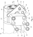
- a hydraulic cylinder 90 is arranged in the area of the rear side 44.5 of the impact rocker 44.
- the hydraulic cylinder 90 serves to support the impact rocker 44 so that the width of the crushing gap S is maintained during the crushing process. Furthermore, the hydraulic cylinder 90 offers the possibility of changing the width of the crushing gap S if this is desired by the machine operator and as is shown in FIG DE 10 2010 015 583 B4 is described as an example.
- the hydraulic cylinder 90 has a cylinder housing 91.
- a piston is adjustably accommodated in this housing.
- a piston rod 92 is connected to the piston.
- a piston rod head 93 which is carried by the piston rod 92, is used for coupling to the impact rocker 44.
- the situation here is such that the piston rod head 93 is pivotably coupled to the impact rocker 44 by means of a bearing 44.4.
- the hydraulic cylinder 90 has hydraulic connections A, B.
- the hydraulic cylinder 90 can be supplied with hydraulic oil via these hydraulic connections A, B.
- the hydraulic cylinder 90 has an overload protection. This is explained below with reference to the Figures 3 and 4 more detailed.
- the end of the hydraulic cylinder 90 is closed with a cover 94 in this rear area. With the cover 94 removed, the pressure chamber of the hydraulic cylinder 90, which is formed between the cylinder base and the piston, is accessible.
- connection area 95 is connected to the cylinder housing 91 of the hydraulic cylinder 90, preferably formed in one piece.
- the connection area 95 has a flat connection surface 95.1.
- This flat connection surface 95.1 encloses a passage opening.
- the passage opening creates a spatial connection to the pressure chamber of the hydraulic cylinder 90.
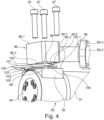
- a bursting plate 100 can be placed on the connection surface 95.1.
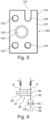
- the rupture disc 100 is in figure 5 more detailed. As this representation shows, the bursting disk 100 has a flat rear side 101 and a flat front side 102 .
- the bursting plate 101 has a bursting piece 104 in the middle.
- the predetermined breaking point 105 can be in the form of a groove, for example, which is made in the front side 102 and/or in the back side 101 .
- the bursting plate 100 has bores 103 .
- three holes 103 are used.
- the rupture disc 100 has a recess 106 in one area, which is open via an insertion section 107 to the edge area of the rupture disc 100 .
- the rupture disk 100 can be installed between the connection area 95 and a rupture disk holder 96 .
- the bursting disk holder 96 has a pressure surface 96.2 on its side facing the bursting disk 100.
- the bursting disk holder 96 can be placed on the back 101 of the bursting disk 100 with this pressure surface 96.2.
- the bursting plate 100 is supported on the connection surface 95.1 of the connection area 95.
- the front side 102 of the bursting plate 100 covers the leadthrough in the connection surface 95.1.
- the bursting plate 100 is then positioned in such a way that the bursting piece 104 comes to rest over the passage.
- FIG 4 illustrates that the rupture disk holder 96 has a passage 96.3. In the mounted state, this bushing 96.3 also comes to rest over the bursting piece 104.
- a channel section of the bursting disk holder 96 connects to the passage 96.3.
- the channel section opens into a hydraulic line 99 in the area of a line connection 99.1 of the bursting disk holder 96.
- the hydraulic line 99 can be designed in such a way that it has a clamping piece 99.3 at its end facing away from the bursting disk holder 96.
- a pipe connection 99.2 can be formed by means of the clamping piece 99.3, to which a further hydraulic line can be detachably coupled.
- the bursting plate holder 96 has four bores, three of which form screw receptacles 96.4 for fastening screws 97.
- the bores run from a top wall 96.1 to the pressure surface 96.2.
- a holding element 98 is inserted into the bore which is not occupied by the fastening screws 97 .
- the holding element 98 is also formed by a screw.
- the retaining element 98 is pushed through the bore and screwed into a threaded receptacle of the connection area 95, the threaded receptacle extending from the connection surface 95.1 into the connection area 95.
- connection area 95 for the fastening screws 97 can be provided in the connection area 95 for the fastening screws 97 .
- the movement is limited by the recess 106 into which the holding element 98 fits.
- the recess 106 together with a bolt section of the holding element 98, forms a pivot bearing about which the bursting disk 100 can be pivoted and brought into its assembly position. Then the holes 103 are aligned with the screw mounts 96.4.
- the fastening screws 97 can now be guided into the screw mounts 96.4 and the bores 103 of the bursting plate 100 and screwed into the threaded mounts of the connection area 95.
- the fastening screws 97 are tightened, the bursting disk 100 is held clamped in its assembly position between the connection area 95 and the bursting disk holder 96 as intended.
- the holding element 98 can also be screwed further into the associated threaded receptacle and the assembly process can thus be completed.
- the bursting piece 104 breaks open in relation to the bursting plate 100 in the area of the predetermined breaking point 105 .
- the hydraulic fluid in the pressure chamber of the hydraulic cylinder 90 can then expand into the channel section of the bursting disk holder 96 through the passage of the connection area 95 and the opening of the bursting disk 100 released by the bursting piece 104 .
- the hydraulic fluid is drained from there via the hydraulic line 99 .
- the overload protection now needs to be repaired.
- the fastening screws 97 can now be loosened and removed in the opposite manner to that described above during the assembly process.
- the holding element 98 is only released, but remains in the in figure 4 position shown, so will not be removed.
- the rupture panel 100 is now released and can be removed.
- the bursting disk 100 can be easily pulled off the holding element 98 , with the holding element 98 leaving the region of the bursting disk 100 through the insertion section 107 .
- the bursting disk holder 96 essentially remains in its assembly position, since it remains held on the connection area 95 by the holding element 98 .
- a new bursting disk 100 can now be used and installed. The overload protection is then ready to be used again.
- FIG 6 shows a schematic representation of the overload protection.
- the pressure chamber is connected to a hydraulic system via the hydraulic port A.
- Another chamber of the hydraulic cylinder 90 is formed on the side of the piston opposite the pressure chamber. This additional chamber is connected to the hydraulic system via the hydraulic connection B.
- the hydraulic oil can be pumped between the pressure chamber and the other chamber via the hydraulic connections A, B.
Landscapes
- Engineering & Computer Science (AREA)
- Food Science & Technology (AREA)
- Mechanical Engineering (AREA)
- General Engineering & Computer Science (AREA)
- Crushing And Grinding (AREA)
Abstract
Description
- Die Erfindung betrifft eine Überlastsicherung für das hydraulische System einer Mineralmaterial-Bearbeitungsanlage, insbesondere für einen Rotationsprallbrecher, einen Backenbrecher oder dgl., wobei ein Hydraulikelement, welches dazu hergerichtet ist Hydraulikflüssigkeit zu bevorraten und/oder zu leiten, vorgesehen ist, wobei das Hydraulikelement einen Anschlussbereich aufweist, der eine Durchtrittsöffnung für Hydraulikfluid des Hydrauliksystems aufweist, wobei die Durchtrittsöffnung mittels einer auswechselbaren Berstplatte überdeckt ist, wobei ein Berstplatten-Halter auf der dem Anschlussbereich abgewandten Rückseite der Berstplatte angeordnet ist, und wobei zumindest eine Befestigungsschraube durch eine Schraubaufnahme des Berstplatten-Halters und eine dazu fluchtend angeordnete Bohrung der Berstplatte hindurchgeführt und in eine Gewindeaufnahme des Anschlussbereichs eingeschraubt ist, derart, dass die Berstplatte zwischen einer Druckfläche des Berstplatten-Halters und einer Anschlussfläche des Anschlussbereichs im Montagezustand geklemmt gehalten ist.
- Aus
DE 10 2010 015 583 B4 ist eine Mineralmaterial-Bearbeitungsanlage, nämlich ein Rotationsprallbrecher bekannt. Dieser Rotationsprallbrecher hat ein Brechaggregat mit einem Brechrotor. Radial außen besitzt der Brechrotor eine Vielzahl von Schlagleisten, die einen Schlagkreis festlegen. Dem Brechrotor steht zumindest ein Wandelement in Form einer Prallschwinge gegenüber. Zwischen der Prallschwinge und dem Schlagkreis ergibt sich ein Brechspalt. - Während des Betriebseinsatzes wird das zu brechende Material in das Brechaggregat eingefüllt. Dort wird es mittels der Schlagleisten radial nach außen geschleudert. Das Material trifft dann auf die Prallschwinge, wodurch es zerkleinert wird. Sobald das Material eine Korngröße aufweist, die kleiner ist als der Brechspalt, fällt es durch den Brechspalt hindurch und gelangt aus dem Bereich des Brechaggregats. Unterhalb des Brechaggregats ist ein Brecherabzugsband angeordnet. Mit diesem kann das gebrochene Material abtransportiert werden.
- Bei Prallbrechern ist die Prallschwinge üblicherweise gegenüber dem Chassis der Brechanlage mit einem Hydraulikzylinder abgestützt. Mit dem Hydraulikzylinder kann die Größe des Brechspalts auf das erforderliche Maß eingestellt und aufrechterhalten werden.
- Für den Fall, dass nicht brechbares Material in den Brechraum des Brechaggregats gelangt, welches durch den eingestellten Brechspalt nicht entweichen kann, ist eine Überlastsicherung vorgesehen.
- Die Überlastsicherung kann eine sogenannte Berstplatte aufweisen. Die Berstplatte dichtet eine Durchtrittsöffnung des Hydraulikzylinders ab. Wirkt eine zu große Kraft auf die Prallschwinge (wie im Fall von nicht brechbarem Material im Brechraum) und damit auch auf den diese abstützenden Hydraulikzylinder. Daraus resultiert ein zu hoher und für das System schädlicher Druck. Um das Hydrauliksystem zu schützen und um Schäden abzuwenden bricht dann die Berstplatte. Dann kann das Hydrauliköl durch die Durchtrittsöffnung aus dem Hydraulikzylinder entweichen und der Hydraulikzylinder einfahren. Dementsprechend kann die Prallschwinge ausweichen und der Brechspalt öffnet sich. Das nicht brechbare Material kann dann durch den so geöffneten Brechspalt entweichen.
- Die Berstplatte ist zwischen dem Gehäuse des Hydraulikzylinders und einem Berstplatten-Halter eingespannt. Üblicherweise werden dabei Schrauben verwendet, die durch Bohrungen des Berstplatten-Halters und der Berstplatte hindurchgeführt und in den Hydraulikzylinder eingeschraubt werden.
- Nach einem Überlastereignis muss die Berstplatte ausgetauscht werden. Hierzu müssen die Befestigungsschrauben gelöst und der Berstplatten-Halter demontiert werden. Das Lösen des Berstplatten-Halters muss sorgfältig vorgenommen werden, da sonst Hydrauliköl auslaufen kann. Weiterhin ist es so, dass im beengten Bauraum der Bearbeitungsanlage das Ausrichten und Befestigen des Berstplatten-Halters an dem Hydraulikzylinder nicht immer einfach möglich ist.
- Es ist daher Aufgabe der Erfindung, eine Überlastsicherung der eingangs erwähnten Art bereitzustellen, die nach einem Überlastfall eine einfache Wartung ermöglicht.
- Diese Aufgabe wird dadurch gelöst, dass wenigstens ein Halteelement vorgesehen ist, das in einer Demontageposition den Berstplatten-Halter an dem Hydraulikelement, insbesondere an dem Anschlussbereich hält, wenn die zumindest eine Befestigungsschraube aus der Gewindeaufnahme des Anschlussbereichs herausgeschraubt und die Berstplatte entfernt ist.
- Wenn nach einem Überlastfall die Überlastsicherung ausgelöst hat, so muss die Berstplatte ausgetauscht werden. Dies gelingt nach der Erfindung einfach dadurch, dass die Befestigungsschrauben entfernt und die Verbindung der Berstplatte im Klemmbereich zwischen dem Berstplatten-Halter und dem Anschlussbereich gelöst wird. Dann kann die Berstplatte entfernt werden. In dieser Demontageposition hält das Halteelement den Berstplatten-Halter an dem Anschlussbereich. Hierbei wird dann vermieden, dass Hydrauliköl, welches sich in dem Berstplatten-Halter befindet, auslaufen kann. Anstelle der beschädigten Berstplatte kann dann eine neue Berstplatte eingesetzt werden. Anschließend kann der Berstplatten-Halter wieder befestigt werden. Da der Berstplatten-Halter mit dem Halteelement in Position gehalten ist, ist dies einfach möglich. Der Monteur muss nun lediglich wieder die Befestigungsschrauben einsetzen und in die Gewindeaufnahmen des Anschlussbereichs einschrauben. Anschließend ist die Überlastsicherung wieder zum erneuten Gebrauch verwendbar.
- Vorzugsweise ist es so, dass das Halteelement den Berstplatten-Halter dann, wenn die Befestigungsschrauben entfernt sind, hinsichtlich seiner Bewegungsmöglichkeiten so eingeschränkt ist, dass er sich nur noch mit einem Freiheitsgrad oder mit zwei Freiheitsgraden bewegen lässt. Beispielsweise ist das Halteelement so gestaltet, dass der Berstplatten-Halter gegenüber dem Anschlussbereich nur noch verdrehbar ist (ein Freiheitsgrad) oder dass er nur noch gegenüber dem Halteelement verdrehbar und quer zur Plattenebene der Berstplatte versetzbar ist.
- Gemäß einer bevorzugten Erfindungsvariante ist es vorgesehen, dass die Berstplatte eine oder mehrere Ausnehmung aufweist, die einen seitlichen Einführabschnitt aufweist, wobei der Einführabschnitt die Ausnehmung zu einer quer zur Plattenebene der Berstplatte verlaufenden Seite hin öffnet, derart, dass das Halteelement quer zur Plattenebene des Berstelements seitlich in die Ausnehmung einschiebbar und aus dieser herausnehmbar ist. Wenn die Befestigungsschrauben entfernt sind, kann die Berstplatte aus dem Bereich zwischen dem Berstplatten-Halter und dem Aufnahmebereich herausgezogen werden. Das Halteelement verbleibt in seiner Position. Wenn dann die neue Berstplatte eingesetzt wird, so kann sie einfach zunächst auf das Halteelement aufgeschoben werden. Das Halteelement fährt durch den Einführabschnitt in die Ausnehmung ein. Entsprechend gelingt die Positionierung der Berstplatte auch bei unübersichtlichen Montageverhältnissen zuverlässig und eindeutig. Weiterhin wird hierdurch auch eine platzsparende Bauweise bewirkt.
- Eine besonders einfache Konstruktion ergibt sich dann, wenn vorgesehen ist, dass das Halteelement von einer Schraube gebildet ist.
- Vorzugsweise kann es dabei auch vorgesehen sein, dass diese Schraube mit einem Bolzenabschnitt in die Ausnehmung eingreift, und dass das Halteelement durch eine Schraubaufnahme des Berstplatten-Halters und die Ausnehmung hindurchgeführt und in eine in die Anschlussfläche des Anschlussbereichs eingebrachte Gewindeaufnahme eingeschraubt ist. Vorzugsweise ist es hierbei möglich, das Halteelement zusätzlich zu den Befestigungsschrauben zur Verspannung des Berstplatten-Halters zu verwenden.
- Wenn vorgesehen ist, dass die Berstplatte mit ihrer ebenen Vorderseite auf der Anschlussfläche des Anschlussbereichs und einer gegenüberliegenden ebenen Rückseite auf der Druckfläche des Berstplatten-Halters anliegt und zwischen der Anschlussfläche und der Druckfläche geklemmt gehalten ist, dann ist es bereits ausreichend, wenn nach der gelösten Klemmverbindung (und entfernten Befestigungsschrauben) sich die Beabstandung des Berstplatten-Halters von dem Aufnahmebereich geringfügig vergrößert. Die Demontage der Berstplatte ist dann einfach möglich, da sie blockadefrei seitlich aus ihrer Montagestellung herausgezogen werden kann. Umgekehrt kann die neue Berstplatte dann leicht in den Spaltbereich zwischen Berstplatten-Halter und Aufnahmebereich eingeschoben werden. Die Gefahr eines Ölverlusts wird hierdurch weiter verringert.
- Eine besonders vorteilhafte Ausgestaltung ergibt sich dann, wenn vorgesehen ist, dass das Halteelement mit einem Abschnitt der Berstplatte, insbesondere mit der Ausnehmung, ein Schwenklager bildet, dessen Schwenkachse quer zu der Anschlussfläche steht, derart dass die Berstplatte dann, wenn die Befestigungsschrauben entfernt sind, quer zur Anschlussfläche aus ihrer Montageposition herausschwenkbar ist. Dies erhöht die Montagefreundlichkeit. Insbesondere kann die neue Berstplatte an dem Schwenklager vorpositioniert und dann leicht in die eingeschwenkte Montageposition gebracht werden.
- Erfindungsgemäß kann es vorgesehen sein, dass die Berstplatte ein Berststück mit einer Sollbruchstelle aufweist, die vorzugsweise in Form einer Querschnittsschwächung ausgebildet ist. Dabei kann es insbesondere so sein, dass das Berststück über die Sollbruchstelle so an die Berstplatte angebunden ist, dass sie im Überlastfall vollständig abgesprengt wird. Vorzugsweise kann es auch so sein, dass das Berststück im Überlastfall über einen Materialabschnitt an die Berstplatte einstückig angebunden bleibt.
- Wenn vorgesehen ist, dass der Berstplatten-Halter eine Durchführung aufweist, die im montierten Zustand des Berstplatten-Halters von der Berstplatte überdeckt ist, dass sich an die Durchführung ein Kanalabschnitt des Berstplatten-Halters anschließt und dass der Kanalabschnitt zu einem Leitungsanschluss führt, an den eine Hydraulikleitung an den Berstplatten-Halter anschließbar oder angeschlossen ist, dann ist garantiert, dass die Berstplatte zuverlässig in Richtung auf die Durchführung auslösen kann. Hierzu stellt die Durchführung einen Bereich bereit, in den die Berstplatte hinein deformiert werden kann. Zudem kann das austretende Hydrauliköl in dem Kanalabschnitt des Berstplatten-Halters gesammelt und dann über den Leitungsanschluss in ein abführendes Leitungssystem geordnet abgeleitet bzw. in einen Sammelbehälter geleitet werden.
- Eine im Rahmen dieser vorliegenden Erfindung bevorzugte Überlastsicherung ist derart, dass das Hydraulikelement ein Hydraulikzylinder ist, der ein Zylindergehäuse aufweist, in dem ein Kolben verstellbar geführt ist, wobei an den Kolben eine Kolbenstange angeschlossen ist, die mit ihrem Kolbenstangenkopf aus dem Hydraulikzylinder herausgeführt ist, wobei der Kolben eine Druckkammer begrenzt, und wobei die Druckkammer in räumlicher Verbindung mit der Durchtrittsöffnung des Anschlussbereichs steht. Vorzugsweise steht dabei die Berstplatte so, dass sich die Berstplatten-Ebene in der Montageposition quer, insbesondere senkrecht zur Bewegungsrichtung des Kolbens erstreckt. Dies erleichtert die Zugänglichkeit zu der Überlastsicherung und damit die Montage bzw. Demontage der Berstplatte.
- Hierbei kann es auch vorzugsweise vorgesehen sein, dass der Hydraulikzylinder, vorzugsweise mit seiner Kolbenstange, an ein Wandelement eines Brechaggregats, mittels eines Schwenklagers angekoppelt ist, und wobei das Wandelement mittels eines Lagers schwenkbar an einem Chassis gehalten ist, wobei vorzugsweise vorgesehen ist, dass das Wandelement eine Prallschwinge eines Rotationsprallbrechers ist.
- Die Aufgabe der Erfindung wird auch gelöst mit einem Verfahren zur Reparatur einer Überlastsicherung einer Mineralmaterial-Bearbeitungsanlage, wobei die Überlastsicherung gemäß einem der Ansprüche 1 bis 9 ausgestaltet ist, wobei die Befestigungsschrauben gelöst und entfernt werden, und dabei der Berstplatten-Halter mittels des Halteelements mit dem Anschlussbereich verbunden bleibt, wobei dann die Berstplatte der Überlastsicherung entnommen und eine neue Berstplatte in die Überlastsicherung eingesetzt wird, und dass dann die Befestigungsschrauben wieder in die Schraubaufnahmen des Berstplatten-Halters und die Bohrungen der neuen Berstplatte eingesetzt und in die Gewindeaufnahmen des Anschlussbereichs eingeschraubt werden.
- Die Erfindung wird im Folgenden anhand eines in den Zeichnungen dargestellten Ausführungsbeispiels näher erläutert. Es zeigen:
- Figur 1
- in schematischer Seitenansicht eine Brechanlage,
- Figur 2
- ein Brechaggregat der Brechanlage gemäß
Figur 1 , - Figur 3
- einen Hydraulikzylinder mit einer Überlastsicherung,
- Figur 4
- die Darstellung gemäß
Figur 3 in einer veränderten Perspektive, - Figur 5
- in Aufsicht eine Berstplatte der Überlastsicherung gemäß den
Figuren 3 und4 und - Figur 6
- eine schematische Darstellung eines Teils des Hydraulikkreises der Brechanlage.
-
Figur 1 zeigt eine Aufbereitungsanlage in Form einer Brechanlage 10. Die Brechanlage 10 ist als mobile Brechanlage ausgebildet und weist daher Fahrwerke 15 auf. Denkbar ist es jedoch auch, dass es sich bei der Brechanlage 10 um eine stationäre Brechanlage handelt. - Die Brechanlage 10 weist ein Chassis 11 auf, welches die Maschinenkomponenten oder zumindest einen Teil der Maschinenkomponenten trägt. An seinem rückwärtigen Ende besitzt das Chassis 11 einen Ausleger 12. Im Bereich des Auslegers 12 ist ein Material-Zuführbereich gebildet.
- Der Material-Zuführbereich umfasst einen Aufgabetrichter 20 und eine Materialzuführeinrichtung 16.
- Der Aufgabetrichter 20 kann zumindest teilweise von Trichterwänden 21, die in Richtung der Längserstreckung der Brechanlage 10 verlaufen, und einer quer zur Längserstreckung verlaufenden Rückwand 22 gebildet sein. Der Aufgabetrichter 20 führt zu der Materialzuführeinrichtung 16.
- Die Materialzuführeinrichtung 16 kann, wie im vorliegenden Ausführungsbeispiel dargestellt, eine Förderrinne aufweisen, die mittels eines Vibrationsantriebs antreibbar ist. Über den Aufgabetrichter 20 kann, beispielsweise mittels eines Radladers, zu zerkleinerndes Gut in die Brechanlage 10 eingefüllt und auf die Förderrinne aufgegeben werden.
- Von der Förderrinne gelangt das zu zerkleinernde Gut in den Bereich einer Siebeinheit 30. Diese Siebeinheit 30 kann auch als Vorsieb-Anordnung bezeichnet werden. Im Bereich der Siebeinheit 30 ist wenigstens ein Siebdeck 30.1, 30.2 angeordnet. Im vorliegenden Ausführungsbeispiel sind zwei Siebdecks 30.1, 30. 2 verwendet.
- An dem oberen Siebdeck 30.1 wird von dem zu zerkleinernden Material eine Teilfraktion ausgesiebt. Diese Teilfraktion hat bereits eine ausreichende Korngröße, die nicht mehr in der Brechanlage 10 zerkleinert werden muss. Insofern kann diese ausgesiebte Teilfraktion in einem Bypasskanal 31 vorbei an einem Brechaggregat 40 geleitet werden.
- Wenn ein zweites Siebdeck 30.2 in der Siebeinheit 30 verwendet ist, so kann aus der Teilfraktion, die unterhalb des Siebdecks 30.1 anfällt, eine weitere Feinpartikel-Fraktion ausgesiebt werden. Diese Feinpartikel-Fraktion wird unterhalb des Siebdecks 30.2 zu einem Seitenaustragband 32 geführt. Von dem Seitenaustragband 32 wird die Feinpartikel-Fraktion abgeleitet und auf eine seitlich der Maschine angeordnete Halde 70.2 gefördert.
- Wie
Figur 1 veranschaulicht, kann es sich bei der Siebeinheit 30 um ein Vibrationssieb mit einem Siebantrieb 33 handeln. Der Siebantrieb 33 versetzt das Siebdeck 30.1 und/oder dass Siebdeck 30.2 in Vibrationsbewegungen. Aufgrund der geneigten Anordnung der Siebdecks 30.1, 30.2 und in Verbindung mit den Vibrationsbewegungen wird ein Materialtransport auf den Siebdecks 30.1, 30.2 hin in Richtung zu dem Brechaggregat 40 bzw. zu dem Bypasskanal 31 bewirkt. - Das von dem Siebdeck 30.1 kommende zu zerkleinernde Material wird dem Brechaggregat 40 zugeleitet, wie dies
Figur 1 erkennen lässt. - Das Brechaggregat 40 kann beispielsweise in Form eines Rotationsprall-Brechaggregats ausgebildet sein. Es kann jedoch auch ein anderes Brechaggregat, beispielsweise ein Backen-Brechaggregat eines Backenbrechers, sein.
- Das Brechaggregat 40 weist einen Brechrotor 42 auf, der von einem Motor 41 angetrieben wird. In
Figur 1 verläuft die Rotationsachse des Brechrotors 42 horizontal in Richtung der Bildtiefe. - Der Brechrotor 42 kann beispielsweise an seinem Außenumfang mit Schlagleisten 43 bestückt sein. Gegenüberliegend dem Brechrotor 42 können beispielsweise Wandelemente, vorzugsweise in Form von Prallschwingen 44 angeordnet sein.
- Bei drehendem Brechrotor 42 wird das zu zerkleinernde Material mittels der Schlagleisten 43 nach außen geschleudert. Dabei trifft dieses Material auf die Prallschwingen 44 und wird aufgrund der hohen kinetischen Energie zerkleinert. Wenn das zu zerkleinernde Material eine ausreichende Korngröße aufweist, die es ermöglicht, dass die Materialteilchen durch den Spalt zwischen den Prallschwingen 44 und den radial äußeren Enden der Schlagleisten 43 hindurchgeführt werden können, so verlässt das zerkleinerte Gut das Brechaggregat 40 über den Brecherauslass 45.
- Denkbar ist es, dass im Bereich des Brecherauslasses 45 das vom Brechaggregat 40 kommende und zerkleinerte Material mit dem aus dem Bypasskanal 31 kommenden Material zusammengeführt und auf einen Bandförderer 13 gebracht wird. Mit dem Bandförderer 13 kann das Material aus dem Arbeitsbereich des Brechaggregats 40 herausgeführt werden.
- Wie die Zeichnungen zeigen, kann der Bandförderer 13 ein endlos umlaufendes Förderband aufweisen, das einen Lasttrum 13.3 und einen Leertrum 13.4 aufweist. Der Lasttrum 13.3 dient dazu das gebrochene Material, welches aus dem Brecherauslass 45 des Brechaggregats 40 fällt, aufzufangen und abzutransportieren. An den Bandenden kann das Förderband zwischen dem Lasttrum 13.3 und dem Leertrum 13.4 mittels Umlenkrollen 13.1, 13.2 umgelenkt werden. Im Bereich zwischen den Umlenkrollen 13.1, 13.2 können Führungen, insbesondere Tragrollen vorgesehen sein, um die Förderrichtung des Förderbands zu verändern, dem Förderband eine bestimmte Form zu geben und/oder das Förderband zu stützen.
- Der Bandförderer 13 weist einen Bandantrieb auf, mittels dem der Bandförderer 13 angetrieben werden kann. Der Bandantrieb kann vorzugsweise am Abwurfende 13.5 oder im Bereich des Abwurfendes 13.5 des Bandförderers 13 angeordnet sein.
- Der Bandförderer 13 kann, beispielsweise mittels des Bandantriebs, an eine Steuereinrichtung mittels einer Steuerleitung angeschlossen sein.
- Es können ein oder mehrere weitere Bandförderer 60 und/oder ein Rückführförderer 80 verwendet sein, die prinzipiell die gleiche Bauweise aufweisen wie der Bandförderer 13. Insofern kann auf die vorstehenden Ausführungen Bezug genommen werden.
- Im Bereich zwischen dem Aufgabeende und dem Abwurfende 13.5 kann ein Magnet 14 oberhalb des Lasttrums 13.3 angeordnet sein. Mit dem Magnet 14 lassen sich Eisenteile aus dem gebrochenen Gut abheben und aus dem Förderbereich des Bandförderers 13 heraus bewegen.
- In Transportrichtung nach dem Bandförderer 13 kann eine Nachsiebvorrichtung 50 angeordnet sein. Die Nachsiebvorrichtung 50 weist ein Siebgehäuse 51 auf, in dem wenigstens ein Siebdeck 52 untergebracht ist. Unterhalb des Siebdecks 52 ist ein Gehäuseunterteil 53 gebildet, welcher als Sammelraum dient für das am Siebdeck 52 ausgesiebte Material.
- Das Gehäuseunterteil schafft über eine Öffnung eine räumliche Verbindung zu einem weiteren Bandförderer 60. Hier bildet der weitere Bandförderer 60 seinen Aufgabebereich 61, wobei das ausgesiebte Material im Aufgabebereich 61 auf den Lasttrum des weiteren Bandförderers 60 geleitet wird. Der weitere Bandförderer 60 fördert das ausgesiebte Material hin zu seinem Abwurfende 62. Von dort gelangt das ausgesiebte Material auf eine Halde 70.1.
- Das am Siebdeck 52 der Nachsiebvorrichtung 50 nicht ausgesiebte Material wird vom Siebdeck 52 auf ein Stichband 54 gefördert. Das Stichband 54 kann ebenfalls als ein Bandförderer ausgebildet sein, sodass auf die oben in Bezug auf den Bandförderer 13 gemachten Ausführungen verwiesen werden kann. Die Transportrichtung des Stichbands 54 verläuft in
Figur 1 in Richtung der Bildtiefe. - An seinem Abwurfende übergibt das Stichband 54 das nicht ausgesiebte Material, das auch als Überkorn bezeichnet wird, auf den Aufgabebereich 81 des Rückführförderers 80. Der Rückführförderer 80, der als Bandförderer ausgebildet sein kann, fördert das Überkorn in Richtung hin zum Aufgabetrichter 20. An seinem Abwurfende 82 übergibt der Rückführförderer 80 das Überkorn in den Materialfluss und zwar vorzugsweise in den Material-Zuführbereich. Das Überkorn kann mithin dem Brechaggregat 40 erneut zugeführt und hier auf die gewünschte Partikelgröße gebrochen werden.
- In
Figur 2 ist das Brechaggregat 40 des Prallbrechers schematisch detaillierter dargestellt. Der Brechrotor 42 ist in einem Gehäuse des Brechaggregats 40 um eine Rotationsachse 42.1 drehbar gelagert. Zum Antrieb des Brechrotors 42 kann der oben erwähnte Motor 41 verwendet werden. - Auf der Rotorperipherie 42.2 sind Schlagleisten 43 montiert. Bei einer Drehung des Brechrotors 42 wird durch die sich ebenfalls drehenden Schlagleisten 43 ein Schlagkreis 42.3 gebildet. Diesem Schlagkreis 42.3 zugeordnet ist gegenüberliegend und in Bewegungsrichtung des Brechguts eine Prallschwinge 44 schwenkbeweglich gelagert. Hierzu wird ein Schwenklager 44.1 verwendet. Die Prallschwinge 44 ist mittels dieses Schwenklagers 44.1 an dem Chassis 11 gelagert.
- Die Prallschwinge 44 weist an ihrer dem Innenraum des Brechaggregats 40 zugewandten Seite ein Wandelement 44.2 auf. Im distalen Endbereich 44.3 steht das Wandelement 44.2 dem Brechrotor 42 derart gegenüber, dass im Bereich zwischen dem Schlagkreis 42.3 und dem distalen Endbereich 44.3 ein Brechspalt S gebildet wird. Unterhalb des Brechaggregats 40 wird der oben beschriebene Brecherauslass 45 gebildet.
- Während des Betriebseinsatzes wird das zu zerkleinernde Material M, welches in
Figur 2 schematisch dargestellt ist, in das Brechaggregat 40 eingefüllt. Dieses Material M wird mittels der sich drehenden Schlagleisten 43 nach außen geschleudert. Es trifft dann auf das Wandelement 44.2 der Prallschwinge 44 und wird sowohl an der Schlagleiste 43 und an der Prallschwinge 44 zerkleinert. Wenn das zerkleinerte Material M eine Korngröße aufweist, die kleiner ist als die Weite des Brechspalts S, so fällt es nach unten und verlässt das Brechaggregat 40 über den Brecherauslass 45. Weist das Material M dann jedoch eine noch nicht ausreichend kleine Korngröße auf, so wird es so lange wiederholt gegen die Prallschwinge 44 geworfen, bis ein ausreichender Zerkleinerungszustand erreicht ist. - Im Bereich der Rückseite 44.5 der Prallschwinge 44 ist ein Hydraulikzylinder 90 angeordnet. Der Hydraulikzylinder 90 dient dazu, die Prallschwinge 44 so abzustützen, dass die Weite des Brechspalts S während des Brechvorgangs aufrechterhalten wird. Weiterhin bietet der Hydraulikzylinder 90 die Möglichkeit die Weite des Brechspalts S zu verändern, wenn dies von dem Maschinenbediener gewünscht wird und wie dies in der
DE 10 2010 015 583 B4 beispielhaft beschrieben ist. - Der Hydraulikzylinder 90 besitzt ein Zylindergehäuse 91. In diesem ist ein Kolben verstellbar aufgenommen. An den Kolben ist eine Kolbenstange 92 angeschlossen. Ein Kolbenstangenkopf 93, welcher von der Kolbenstange 92 getragen ist, dient zur Ankopplung an die Prallschwinge 44. Dabei ist es so, dass der Kolbenstangenkopf 93 mittels eines Lagers 44.4 schwenkbar an die Prallschwinge 44 angekoppelt ist.
- In
Figur 2 ist veranschaulicht, dass der Hydraulikzylinder 90 Hydraulikanschlüsse A, B aufweist. Über diese Hydraulikanschlüsse A, B kann der Hydraulikzylinder 90 mit Hydrauliköl versorgt werden. - Gemäß der Erfindung weist der Hydraulikzylinder 90 eine Überlastsicherung auf. Dies wird im Folgenden unter Bezugnahme auf die
Figuren 3 und4 näher detailliert. - In diesen Darstellungen ist der der Prallschwinge 44 abgewandte rückwärtige Bereich des Hydraulikzylinders 90 vergrößert dargestellt.
- Der Hydraulikzylinder 90 ist an diesem rückwärtigen Bereich endseitig mit einem Deckel 94 verschlossen. Bei abgenommenem Deckel 94 ist die Druckkammer des Hydraulikzylinders 90, welche zwischen dem Zylinderboden und dem Kolben gebildet ist, zugänglich.
- An das Zylindergehäuse 91 des Hydraulikzylinders 90 ist ein Anschlussbereich 95 angeschlossen, vorzugsweise einteilig angeformt. Der Anschlussbereich 95 weist eine ebene Anschlussfläche 95.1 auf. Diese ebene Anschlussfläche 95.1 umschließt eine Durchtrittsöffnung. Die Durchtrittsöffnung schafft eine räumliche Verbindung zu der Druckkammer des Hydraulikzylinders 90.
- Wie die Zeichnungen erkennen lassen, kann auf die Anschlussfläche 95.1 eine Berstplatte 100 aufgesetzt werden.
- Die Berstplatte 100 ist in
Figur 5 näher detailliert. Wie diese Darstellung zeigt, weist die Berstplatte 100 eine ebene Rückseite 101 und eine ebene Vorderseite 102 auf. Mittig besitzt die Berstplatte 101 ein Berststück 104. Das Berststück 104 ist über eine, vorzugsweise umlaufend ausgebildete Sollbruchstelle 105 einteilig mit der Berstplatte 100 verbunden. Die Sollbruchstelle 105 kann beispielsweise in Form einer Nut ausgebildet sein, die in die Vorderseite 102 und/oder in die Rückseite 101 eingebracht ist. - Die Berstplatte 100 weist Bohrungen 103 auf. Im vorliegenden Ausführungsbeispiel sind drei Bohrungen 103 verwendet. Selbstverständlich ist es auch denkbar, dass eine abweichende Anzahl von Bohrungen 103, insbesondere auch nur eine Bohrung 103 verwendet ist.
- Die Berstplatte 100 besitzt in einem Bereich eine Ausnehmung 106, die über einen Einführabschnitt 107 zum Randbereich der Berstplatte 100 hin geöffnet ist.
- Wie die
Figuren 3 und4 veranschaulichen, kann die Berstplatte 100 zwischen dem Anschlussbereich 95 und einem Berstplatten-Halter 96 verbaut werden. - Der Berstplatten-Halter 96 besitzt an seiner der Berstplatte 100 zugewandten Seite eine Druckfläche 96.2. Mit dieser Druckfläche 96.2 kann der Berstplatten-Halter 96 auf die Rückseite 101 der Berstplatte 100 aufgesetzt werden. An ihrer Vorderseite 102 stützt sich die Berstplatte 100 auf der Anschlussfläche 95.1 des Anschlussbereichs 95 ab. Im montierten Zustand überdeckt die Vorderseite 102 der Berstplatte 100 die Durchführung in der Anschlussfläche 95.1. Dabei ist dann die Berstplatte 100 so positioniert, dass das Berststück 104 über der Durchführung zum Liegen kommt.
-
Figur 4 veranschaulicht, dass der Berstplatten-Halter 96 eine Durchführung 96.3 aufweist. Im montierten Zustand kommt diese Durchführung 96.3 ebenfalls über dem Berststück 104 zum Liegen. An die Durchführung 96.3 schließt sich ein Kanalabschnitt des Berstplatten-Halters 96 an. Der Kanalabschnitt mündet im Bereich eines Leitungsanschlusses 99.1 des Berstplatten-Halters 96 in eine Hydraulikleitung 99. Die Hydraulikleitung 99 kann so ausgebildet sein, dass sie an ihrem dem Berstplatten-Halter 96 abgewandten Ende ein Klemmstück 99.3 aufweist. Mittels des Klemmstücks 99.3 kann ein Rohranschluss 99.2 gebildet werden, an den eine weitere Hydraulikleitung lösbar angekoppelt werden kann. - Der Berstplatten-Halter 96 besitzt vier Bohrungen, von denen drei Schraubaufnahmen 96.4 für Befestigungsschrauben 97 bilden. Die Bohrungen verlaufenden ausgehend von einer Deckwand 96.1 hin zu der Druckfläche 96.2.
- In die Bohrung, welche nicht mit den Befestigungsschrauben 97 belegt ist, ist ein Halteelement 98 eingesetzt.
- Das Halteelement 98 ist ebenfalls von einer Schraube gebildet. Das Halteelement 98 ist durch die Bohrung hindurchgesteckt und in eine Gewindeaufnahme des Anschlussbereichs 95 eingeschraubt, wobei sich die Gewindeaufnahme ausgehend von der Anschlussfläche 95.1 in den Anschlussbereich 95 hinein erstreckt.
- In gleicher Weise können drei weitere Gewindeaufnahmen in dem Anschlussbereich 95 für die Befestigungsschrauben 97 vorgesehen sein.
- Zur Montage der Berstplatte 100 kann diese, wie
Figur 3 und4 veranschaulichen, mit ihrem Einführabschnitt 107 auf das montierte Halteelement 98 im Bereich zwischen dem Berstplatten-Halter 96 und dem Anschlussbereich 95 aufgeschoben werden. Die Bewegung wird mit der Ausnehmung 106 begrenzt, in die sich das Halteelement 98 fügt. - Die Ausnehmung 106 bildet zusammen mit einem Bolzenabschnitt des Halteelements 98 eine Schwenklagerung, um die die Berstplatte 100 geschwenkt und in ihre Montageposition gebracht werden kann. Dann stehen die Bohrungen 103 in Flucht zu den Schraubaufnahmen 96.4.
- Nun können die Befestigungsschrauben 97 in die Schraubaufnahmen 96.4 und die Bohrungen 103 der Berstplatte 100 hindurchgeführt und in die Gewindeaufnahmen des Anschlussbereichs 95 eingeschraubt werden. Wenn die Befestigungsschrauben 97 angespannt werden, so wird die Berstplatte 100 bestimmungsgemäß in ihrer Montageposition zwischen dem Anschlussbereich 95 und dem Berstplatten-Halter 96 geklemmt gehalten. Abschließend kann auch das Halteelement 98 weiter in die zugeordnete Gewindeaufnahme eingeschraubt und der Montagevorgang damit abgeschlossen werden.
- Wenn nun während des Betriebs eine Überlastsituation auftritt, so bricht das Berststück 104 gegenüber der Berstplatte 100 im Bereich der Sollbruchstelle 105 auf.
- Die Hydraulikflüssigkeit in der Druckkammer des Hydraulikzylinders 90 kann sich dann durch die Durchführung des Anschlussbereichs 95 und die von dem Berststück 104 freigegebene Öffnung der Berstplatte 100 hinein in den Kanalabschnitt des Berstplatten-Halters 96 entspannen. Von dort wird die Hydraulikflüssigkeit über die Hydraulikleitung 99 abgeleitet.
- Nun ist eine Reparatur der Überlastsicherung erforderlich. In umgekehrter Weise, wie dies oben beim Montagevorgang beschrieben ist, können nun die Befestigungsschrauben 97 gelöst und entfernt werden. Das Halteelement 98 wird nur gelöst, verbleibt aber in der in
Figur 4 gezeigten Position, wird also nicht entfernt. Die Berstplatte 100 ist nun freigegeben und kann abgenommen werden. Hierzu lässt sich die Berstplatte 100 einfach von dem Halteelement 98 abziehen, wobei das Halteelement 98 den Bereich der Berstplatte 100 durch den Einführabschnitt 107 verlässt. Erkennbar verbleibt der Berstplatten-Halter 96 im Wesentlichen in seiner Montageposition, da er mit dem Halteelement 98 an dem Anschlussbereich 95 gehalten bleibt. Wie oben beschrieben, kann nun eine neue Berstplatte 100 eingesetzt und verbaut werden. Die Überlastsicherung ist dann wieder zur erneuten Verwendung bereit. -
Figur 6 zeigt eine schematische Darstellung der Überlastsicherung. Wie diese Darstellung veranschaulicht, steht die Druckkammer über den Hydraulikanschluss A mit einem Hydrauliksystem in Verbindung. Auf der der Druckkammer gegenüberliegenden Seite des Kolbens ist eine weitere Kammer des Hydraulikzylinders 90 gebildet. Diese weitere Kammer steht über den Hydraulikanschluss B mit dem Hydrauliksystem in Verbindung. Zur Einstellung des Brechspalts S kann das Hydrauliköl zwischen der Druckkammer und der weiteren Kammer über die Hydraulikanschlüsse A, B umgepumpt werden.
Claims (10)
- Überlastsicherung für das hydraulische System einer Mineralmaterial-Bearbeitungsanlage, insbesondere für einen Rotationsprallbrecher, einen Backenbrecher oder dgl.,wobei ein Hydraulikelement, welches dazu hergerichtet ist Hydraulikflüssigkeit zu bevorraten und/oder zu leiten vorgesehen ist,wobei das Hydraulikelement einen Anschlussbereich (95) aufweist, der eine Durchtrittsöffnung für Hydraulikfluid des Hydrauliksystems aufweist,wobei die Durchtrittsöffnung mittels einer auswechselbaren Berstplatte (100) überdeckt ist,wobei ein Berstplatten-Halter (96) auf der dem Anschlussbereich (95) abgewandten Rückseite (101) der Berstplatte (100) angeordnet ist,und wobei zumindest eine Befestigungsschraube (97) durch eine Schraubaufnahme (96.4) des Berstplatten-Halters (96) und eine dazu fluchtend angeordnete Bohrung (103) der Berstplatte (100) hindurchgeführt und in eine Gewindeaufnahme des Anschlussbereichs (95) eingeschraubt ist, derart, dass die Berstplatte (100) zwischen einer Druckfläche (96.2) des Berstplatten-Halters (96) und einer Anschlussfläche (95.1) des Anschlussbereichs (95) im Montagezustand geklemmt gehalten ist, dadurch gekennzeichnet,dass wenigstens ein Halteelement (98) vorgesehen ist, das in einer Demontageposition den Berstplatten-Halter (96) an dem Hydraulikelement, insbesondere an dem Anschlussbereich (95) hält, wenn die zumindest eine Befestigungsschraube (97) aus der Gewindeaufnahme des Anschlussbereichs (95) herausgeschraubt und die Berstplatte (100) entfernt ist.
- Überlastsicherung nach Anspruch 1, dadurch gekennzeichnet, dass die Berstplatte (100) eine oder mehrere Ausnehmungen (106) aufweist, die einen seitlichen Einführabschnitts (107) aufweist, wobei der Einführabschnitt (107) die Ausnehmung (106) zu einer quer zur Plattenebene der Berstplatte (100) verlaufenden Seite hin öffnet, derart, dass das Halteelement (98) quer zur Plattenebene des Berstelements (100) seitlich in die Ausnehmung (106) einschiebbar und aus dieser herausnehmbar ist.
- Überlastsicherung nach Anspruch 1 oder 2, dadurch gekennzeichnet, dass das Halteelement (98) von einer Schraube gebildet ist, wobei vorzugsweise vorgesehen ist, dass diese Schraube mit einem Bolzenabschnitt in die Ausnehmung (106) eingreift, und dass das Halteelement (98) durch eine Schraubaufnahme (96.4) des Berstplatten-Halters (96) und die Ausnehmung (106) hindurchgeführt und in eine in die Anschlussfläche (95.1) des Anschlussbereichs (95) eingebrachte Gewindeaufnahme eingeschraubt ist.
- Überlastsicherung nach einem der Ansprüche 1 bis 3, dadurch gekennzeichnet, dass die Berstplatte (100) mit ihrer ebenen Vorderseite (102) auf der Anschlussfläche (95.1) des Anschlussbereichs (95) und einer gegenüberliegenden ebenen Rückseite (101) auf der Druckfläche (96.2) des Berstplatten-Halters (96) anliegt und zwischen der Anschlussfläche (95.1) und der Druckfläche (96.2) geklemmt gehalten ist.
- Überlastsicherung nach einem der Ansprüche 1 bis 4, dadurch gekennzeichnet, dass das Halteelement (98) mit einem Abschnitt der Berstplatte (100), insbesondere mit der Ausnehmung (106), ein Schwenklager bildet, dessen Schwenkachse quer zu der Anschlussfläche (95.1) steht, derart dass die Berstplatte (100) dann, wenn die Befestigungsschrauben (97) entfernt sind quer zur Anschlussfläche (95.1) aus ihrer Montageposition herausschwenkbar ist.
- Überlastsicherung nach einem der Ansprüche 1 bis 5, dadurch gekennzeichnet, dass die Berstplatte (100) ein Berststück (104) mit einer Sollbruchstelle (105) auf aufweist, die vorzugsweise in Form einer Querschnittsschwächung ausgebildet ist.
- Überlastsicherung nach einem der Ansprüche 1 bis 6, dadurch gekennzeichnet, dass der Berstplatten-Halter (96) eine Durchführung (96.3) aufweist, die im montierten Zustand des Berstplatten-Halters (96) von der Berstplatte (100) überdeckt ist, dass sich an die Durchführung (96.3) ein Kanalabschnitt des Berstplatten-Halters (96) anschließt und dass der Kanalabschnitt zu einem Leitungsanschluss (99.1) führt, an den eine Hydraulikleitung (99) an den Berstplatten-Halter (96) anschließbar oder angeschlossen ist.
- Überlastsicherung nach einem der Ansprüche 1 bis 7, dadurch gekennzeichnet, dass das Hydraulikelement ein Hydraulikzylinder (90) ist, der ein Zylindergehäuse (91) aufweist, in dem ein Kolben verstellbar geführt ist, wobei an den Kolben eine Kolbenstange (92) angeschlossen ist, die mit ihrem Kolbenstangenkopf (93) aus dem Hydraulikzylinder (90) herausgeführt ist, wobei der Kolben eine Druckkammer begrenzt, und wobei die Druckkammer in räumlicher Verbindung mit der Durchtrittsöffnung des Anschlussbereichs (95) steht.
- Überlastsicherung nach Anspruch 8, dadurch gekennzeichnet, dass der Hydraulikzylinder (90), vorzugsweise mit seiner Kolbenstange (92), an ein Wandelement (44.2) eines Brechaggregats (40), mittels eines Schwenklagers (44.4) angekoppelt ist, und wobei das Wandelement (44.2) mittels eines Lagers (44.1) schwenkbar an einem Chassis (11) gehalten ist, wobei vorzugsweise vorgesehen ist, dass das Wandelement (44.2) Teil einer Prallschwinge (44) eines Rotationsprallbrechers ist.
- Verfahren zur Reparatur einer Überlastsicherung einer Mineralmaterial-Bearbeitungsanlage, wobei die Überlastsicherung gemäß einem der Ansprüche 1 bis 9 ausgestaltet ist, wobei die Befestigungsschrauben (97) gelöst und entfernt werden, und dabei der Berstplatten-Halter (96) mittels des Halteelements (98) mit dem Anschlussbereich (95) verbunden bleibt, wobei dann die Berstplatte (100) der Überlastsicherung entnommen und eine neue Berstplatte (100) in die Überlastsicherung eingesetzt wird, und dass dann die Befestigungsschrauben (97) wieder in die Schraubaufnahmen (96.4) des Berstplatten-Halters (96) und die Bohrungen (103) der neuen Berstplatte (100) eingesetzt und in die Gewindeaufnahmen des Anschlussbereichs (95) eingeschraubt werden.
Applications Claiming Priority (1)
| Application Number | Priority Date | Filing Date | Title |
|---|---|---|---|
| DE102022102283.8A DE102022102283B4 (de) | 2022-02-01 | 2022-02-01 | Überlastsicherung für das hydraulische System einer Mineralmaterial-Bearbeitungsanlage |
Publications (3)
| Publication Number | Publication Date |
|---|---|
| EP4227005A1 true EP4227005A1 (de) | 2023-08-16 |
| EP4227005B1 EP4227005B1 (de) | 2024-07-31 |
| EP4227005C0 EP4227005C0 (de) | 2024-07-31 |
Family
ID=84982250
Family Applications (1)
| Application Number | Title | Priority Date | Filing Date |
|---|---|---|---|
| EP23152225.1A Active EP4227005B1 (de) | 2022-02-01 | 2023-01-18 | Überlastsicherung für das hydraulische system einer mineralmaterial-bearbeitungsanlage |
Country Status (4)
| Country | Link |
|---|---|
| US (1) | US12420286B2 (de) |
| EP (1) | EP4227005B1 (de) |
| CN (1) | CN116532221A (de) |
| DE (1) | DE102022102283B4 (de) |
Families Citing this family (1)
| Publication number | Priority date | Publication date | Assignee | Title |
|---|---|---|---|---|
| CN119531878B (zh) * | 2025-01-21 | 2025-05-30 | 上海山美环保装备股份有限公司 | 一种阶梯式矿山采石工作面原位矿石移动式头段处理工艺 |
Citations (3)
| Publication number | Priority date | Publication date | Assignee | Title |
|---|---|---|---|---|
| EP2042238A1 (de) * | 2007-09-26 | 2009-04-01 | BMH Technology Oy | Brechrotoranordnung |
| DE102010015583B4 (de) | 2010-04-19 | 2018-07-19 | Kleemann Gmbh | Verfahren zur Einstellung eines Arbeitsspaltes zwischen einer Prallschwinge und dem Schlagkreis eines Rotors |
| US20210370308A1 (en) * | 2020-05-26 | 2021-12-02 | Kleemann Gmbh | Crusher |
Family Cites Families (9)
| Publication number | Priority date | Publication date | Assignee | Title |
|---|---|---|---|---|
| US2663458A (en) * | 1950-05-11 | 1953-12-22 | Jr William F Macglashan | Rupture diaphragm unit |
| US3109553A (en) * | 1961-07-17 | 1963-11-05 | Fike Metal Prod Corp | Rupture disc unit |
| GB1151216A (en) * | 1965-08-16 | 1969-05-07 | Fluidrive Eng Co Ltd | Hydraulic Turbo Couplings |
| US3480301A (en) * | 1968-06-27 | 1969-11-25 | Walter H Kroening | Self-centering gauge ring |
| US4751938A (en) * | 1981-09-23 | 1988-06-21 | Bs&B Safety Systems, Inc. | Apparatus for supporting structure between bolted flanges |
| DE4414919A1 (de) * | 1994-04-28 | 1995-11-02 | Boehringer Paul | Horizontal-Backenbrecher |
| JP2000288413A (ja) * | 1999-03-31 | 2000-10-17 | Kurimoto Ltd | スラグクラッシャ |
| US8322360B2 (en) * | 2009-08-07 | 2012-12-04 | Oklahoma Safety Equipment Company, Inc. | Rupture panel |
| DE102014106696A1 (de) * | 2014-05-13 | 2015-11-19 | Claas Selbstfahrende Erntemaschinen Gmbh | Feldhäcksler |
-
2022
- 2022-02-01 DE DE102022102283.8A patent/DE102022102283B4/de active Active
-
2023
- 2023-01-18 EP EP23152225.1A patent/EP4227005B1/de active Active
- 2023-01-23 US US18/099,993 patent/US12420286B2/en active Active
- 2023-02-01 CN CN202310049484.8A patent/CN116532221A/zh active Pending
Patent Citations (3)
| Publication number | Priority date | Publication date | Assignee | Title |
|---|---|---|---|---|
| EP2042238A1 (de) * | 2007-09-26 | 2009-04-01 | BMH Technology Oy | Brechrotoranordnung |
| DE102010015583B4 (de) | 2010-04-19 | 2018-07-19 | Kleemann Gmbh | Verfahren zur Einstellung eines Arbeitsspaltes zwischen einer Prallschwinge und dem Schlagkreis eines Rotors |
| US20210370308A1 (en) * | 2020-05-26 | 2021-12-02 | Kleemann Gmbh | Crusher |
Also Published As
| Publication number | Publication date |
|---|---|
| US20230241617A1 (en) | 2023-08-03 |
| DE102022102283B4 (de) | 2023-08-10 |
| DE102022102283A1 (de) | 2023-08-03 |
| CN116532221A (zh) | 2023-08-04 |
| EP4227005B1 (de) | 2024-07-31 |
| US12420286B2 (en) | 2025-09-23 |
| EP4227005C0 (de) | 2024-07-31 |
Similar Documents
| Publication | Publication Date | Title |
|---|---|---|
| DE10305589B4 (de) | Siebanordnung | |
| EP3291915B1 (de) | Zerkleinerungsmaschine mit einem rotorsystem und verfahren zum zerkleinern von aufgabegut | |
| WO2007122004A1 (de) | Zerkleinerungsvorrichtung | |
| DE29811073U1 (de) | Vorrichtung zum Sieben und/oder Zerkleinern von Siebmaterialien | |
| DE102009060523A1 (de) | Zerkleinerungsvorrichtung mit Gegenmessereinrichtung | |
| DE102020101863A1 (de) | Brechanlage | |
| DE2543769C3 (de) | Zerkleinerungsmaschine mit in einem Gehäuse umlaufendem Rotor und im Gehäuse befestigten Werkzeug | |
| WO2016131433A1 (de) | Zerkleinerungsvorrichtung | |
| DE3519516C2 (de) | Zerkleinerungsmaschine mit umlaufendem Rotor | |
| DE102022102283B4 (de) | Überlastsicherung für das hydraulische System einer Mineralmaterial-Bearbeitungsanlage | |
| EP1960108A1 (de) | Rotor für eine prallmühle | |
| DE3807983C2 (de) | Vorrichtung zum Zerkleinern | |
| EP3385452B1 (de) | Bodenrecycler mit einem schaufelgehäuse | |
| EP0969932A1 (de) | Gehäuse für eine zerkleinerungsmaschine | |
| EP2251085A2 (de) | Vorrichtung zum Bearbeiten von Aufgabegut mit einem Rotor-Stator-System | |
| EP3799961A2 (de) | Wellenzerkleinerer | |
| DE19700655C1 (de) | Transportvorrichtung für Abfall und Verfahren zum Transport von Abfall | |
| EP1050391B1 (de) | Schlagzerspaner zum Zerspanen von Hackschnitzeln zu Spänen | |
| EP2104766B1 (de) | Siebapparat für eine verschmutzte faserstoffsuspension und seine verwendung | |
| AT523406A4 (de) | Zerkleinerungsmaschine | |
| DE102021119918B4 (de) | Aufbereitungsanlage | |
| DE3905682C2 (de) | ||
| DE1930038C3 (de) | Hammerbrecher | |
| DE102019007192A1 (de) | Vorrichtung zum Zerkleinern von schüttfähigem Aufgabegut sowie Verfahren zum Öffnen einer solchen Vorrichtung | |
| DE202022002968U1 (de) | Zerkleinerungsmaschine |
Legal Events
| Date | Code | Title | Description |
|---|---|---|---|
| PUAI | Public reference made under article 153(3) epc to a published international application that has entered the european phase |
Free format text: ORIGINAL CODE: 0009012 |
|
| STAA | Information on the status of an ep patent application or granted ep patent |
Free format text: STATUS: THE APPLICATION HAS BEEN PUBLISHED |
|
| AK | Designated contracting states |
Kind code of ref document: A1 Designated state(s): AL AT BE BG CH CY CZ DE DK EE ES FI FR GB GR HR HU IE IS IT LI LT LU LV MC ME MK MT NL NO PL PT RO RS SE SI SK SM TR |
|
| STAA | Information on the status of an ep patent application or granted ep patent |
Free format text: STATUS: REQUEST FOR EXAMINATION WAS MADE |
|
| 17P | Request for examination filed |
Effective date: 20240130 |
|
| RBV | Designated contracting states (corrected) |
Designated state(s): AL AT BE BG CH CY CZ DE DK EE ES FI FR GB GR HR HU IE IS IT LI LT LU LV MC ME MK MT NL NO PL PT RO RS SE SI SK SM TR |
|
| GRAP | Despatch of communication of intention to grant a patent |
Free format text: ORIGINAL CODE: EPIDOSNIGR1 |
|
| STAA | Information on the status of an ep patent application or granted ep patent |
Free format text: STATUS: GRANT OF PATENT IS INTENDED |
|
| GRAS | Grant fee paid |
Free format text: ORIGINAL CODE: EPIDOSNIGR3 |
|
| INTG | Intention to grant announced |
Effective date: 20240521 |
|
| GRAA | (expected) grant |
Free format text: ORIGINAL CODE: 0009210 |
|
| STAA | Information on the status of an ep patent application or granted ep patent |
Free format text: STATUS: THE PATENT HAS BEEN GRANTED |
|
| AK | Designated contracting states |
Kind code of ref document: B1 Designated state(s): AL AT BE BG CH CY CZ DE DK EE ES FI FR GB GR HR HU IE IS IT LI LT LU LV MC ME MK MT NL NO PL PT RO RS SE SI SK SM TR |
|
| REG | Reference to a national code |
Ref country code: CH Ref legal event code: EP Ref country code: GB Ref legal event code: FG4D Free format text: NOT ENGLISH |
|
| REG | Reference to a national code |
Ref country code: DE Ref legal event code: R096 Ref document number: 502023000090 Country of ref document: DE |
|
| REG | Reference to a national code |
Ref country code: IE Ref legal event code: FG4D Free format text: LANGUAGE OF EP DOCUMENT: GERMAN |
|
| U01 | Request for unitary effect filed |
Effective date: 20240731 |
|
| U07 | Unitary effect registered |
Designated state(s): AT BE BG DE DK EE FI FR IT LT LU LV MT NL PT SE SI Effective date: 20240812 |
|
| PG25 | Lapsed in a contracting state [announced via postgrant information from national office to epo] |
Ref country code: NO Free format text: LAPSE BECAUSE OF FAILURE TO SUBMIT A TRANSLATION OF THE DESCRIPTION OR TO PAY THE FEE WITHIN THE PRESCRIBED TIME-LIMIT Effective date: 20241031 |
|
| PG25 | Lapsed in a contracting state [announced via postgrant information from national office to epo] |
Ref country code: GR Free format text: LAPSE BECAUSE OF FAILURE TO SUBMIT A TRANSLATION OF THE DESCRIPTION OR TO PAY THE FEE WITHIN THE PRESCRIBED TIME-LIMIT Effective date: 20241101 Ref country code: PL Free format text: LAPSE BECAUSE OF FAILURE TO SUBMIT A TRANSLATION OF THE DESCRIPTION OR TO PAY THE FEE WITHIN THE PRESCRIBED TIME-LIMIT Effective date: 20240731 |
|
| PG25 | Lapsed in a contracting state [announced via postgrant information from national office to epo] |
Ref country code: IS Free format text: LAPSE BECAUSE OF FAILURE TO SUBMIT A TRANSLATION OF THE DESCRIPTION OR TO PAY THE FEE WITHIN THE PRESCRIBED TIME-LIMIT Effective date: 20241130 |
|
| PG25 | Lapsed in a contracting state [announced via postgrant information from national office to epo] |
Ref country code: HR Free format text: LAPSE BECAUSE OF FAILURE TO SUBMIT A TRANSLATION OF THE DESCRIPTION OR TO PAY THE FEE WITHIN THE PRESCRIBED TIME-LIMIT Effective date: 20240731 |
|
| PG25 | Lapsed in a contracting state [announced via postgrant information from national office to epo] |
Ref country code: RS Free format text: LAPSE BECAUSE OF FAILURE TO SUBMIT A TRANSLATION OF THE DESCRIPTION OR TO PAY THE FEE WITHIN THE PRESCRIBED TIME-LIMIT Effective date: 20241031 Ref country code: ES Free format text: LAPSE BECAUSE OF FAILURE TO SUBMIT A TRANSLATION OF THE DESCRIPTION OR TO PAY THE FEE WITHIN THE PRESCRIBED TIME-LIMIT Effective date: 20240731 |
|
| PG25 | Lapsed in a contracting state [announced via postgrant information from national office to epo] |
Ref country code: RS Free format text: LAPSE BECAUSE OF FAILURE TO SUBMIT A TRANSLATION OF THE DESCRIPTION OR TO PAY THE FEE WITHIN THE PRESCRIBED TIME-LIMIT Effective date: 20241031 Ref country code: PL Free format text: LAPSE BECAUSE OF FAILURE TO SUBMIT A TRANSLATION OF THE DESCRIPTION OR TO PAY THE FEE WITHIN THE PRESCRIBED TIME-LIMIT Effective date: 20240731 Ref country code: NO Free format text: LAPSE BECAUSE OF FAILURE TO SUBMIT A TRANSLATION OF THE DESCRIPTION OR TO PAY THE FEE WITHIN THE PRESCRIBED TIME-LIMIT Effective date: 20241031 Ref country code: IS Free format text: LAPSE BECAUSE OF FAILURE TO SUBMIT A TRANSLATION OF THE DESCRIPTION OR TO PAY THE FEE WITHIN THE PRESCRIBED TIME-LIMIT Effective date: 20241130 Ref country code: HR Free format text: LAPSE BECAUSE OF FAILURE TO SUBMIT A TRANSLATION OF THE DESCRIPTION OR TO PAY THE FEE WITHIN THE PRESCRIBED TIME-LIMIT Effective date: 20240731 Ref country code: GR Free format text: LAPSE BECAUSE OF FAILURE TO SUBMIT A TRANSLATION OF THE DESCRIPTION OR TO PAY THE FEE WITHIN THE PRESCRIBED TIME-LIMIT Effective date: 20241101 Ref country code: ES Free format text: LAPSE BECAUSE OF FAILURE TO SUBMIT A TRANSLATION OF THE DESCRIPTION OR TO PAY THE FEE WITHIN THE PRESCRIBED TIME-LIMIT Effective date: 20240731 |
|
| U20 | Renewal fee for the european patent with unitary effect paid |
Year of fee payment: 3 Effective date: 20250127 |
|
| PG25 | Lapsed in a contracting state [announced via postgrant information from national office to epo] |
Ref country code: SM Free format text: LAPSE BECAUSE OF FAILURE TO SUBMIT A TRANSLATION OF THE DESCRIPTION OR TO PAY THE FEE WITHIN THE PRESCRIBED TIME-LIMIT Effective date: 20240731 |
|
| PG25 | Lapsed in a contracting state [announced via postgrant information from national office to epo] |
Ref country code: CZ Free format text: LAPSE BECAUSE OF FAILURE TO SUBMIT A TRANSLATION OF THE DESCRIPTION OR TO PAY THE FEE WITHIN THE PRESCRIBED TIME-LIMIT Effective date: 20240731 |
|
| PG25 | Lapsed in a contracting state [announced via postgrant information from national office to epo] |
Ref country code: SK Free format text: LAPSE BECAUSE OF FAILURE TO SUBMIT A TRANSLATION OF THE DESCRIPTION OR TO PAY THE FEE WITHIN THE PRESCRIBED TIME-LIMIT Effective date: 20240731 |
|
| PLBE | No opposition filed within time limit |
Free format text: ORIGINAL CODE: 0009261 |
|
| STAA | Information on the status of an ep patent application or granted ep patent |
Free format text: STATUS: NO OPPOSITION FILED WITHIN TIME LIMIT |
|
| 26N | No opposition filed |
Effective date: 20250501 |
|
| PG25 | Lapsed in a contracting state [announced via postgrant information from national office to epo] |
Ref country code: MC Free format text: LAPSE BECAUSE OF FAILURE TO SUBMIT A TRANSLATION OF THE DESCRIPTION OR TO PAY THE FEE WITHIN THE PRESCRIBED TIME-LIMIT Effective date: 20240731 |
|
| PG25 | Lapsed in a contracting state [announced via postgrant information from national office to epo] |
Ref country code: IE Free format text: LAPSE BECAUSE OF NON-PAYMENT OF DUE FEES Effective date: 20250118 |
|
| REG | Reference to a national code |
Ref country code: CH Ref legal event code: U11 Free format text: ST27 STATUS EVENT CODE: U-0-0-U10-U11 (AS PROVIDED BY THE NATIONAL OFFICE) Effective date: 20260201 |
|
| U20 | Renewal fee for the european patent with unitary effect paid |
Year of fee payment: 4 Effective date: 20260128 |
|
| PG25 | Lapsed in a contracting state [announced via postgrant information from national office to epo] |
Ref country code: RO Free format text: LAPSE BECAUSE OF FAILURE TO SUBMIT A TRANSLATION OF THE DESCRIPTION OR TO PAY THE FEE WITHIN THE PRESCRIBED TIME-LIMIT Effective date: 20240731 |