EP4227008A1 - Dispositif d'impression - Google Patents
Dispositif d'impression Download PDFInfo
- Publication number
- EP4227008A1 EP4227008A1 EP21879807.2A EP21879807A EP4227008A1 EP 4227008 A1 EP4227008 A1 EP 4227008A1 EP 21879807 A EP21879807 A EP 21879807A EP 4227008 A1 EP4227008 A1 EP 4227008A1
- Authority
- EP
- European Patent Office
- Prior art keywords
- annular member
- printing
- curing unit
- printing device
- passing
- Prior art date
- Legal status (The legal status is an assumption and is not a legal conclusion. Google has not performed a legal analysis and makes no representation as to the accuracy of the status listed.)
- Granted
Links
Images



Classifications
-
- B—PERFORMING OPERATIONS; TRANSPORTING
- B41—PRINTING; LINING MACHINES; TYPEWRITERS; STAMPS
- B41J—TYPEWRITERS; SELECTIVE PRINTING MECHANISMS, i.e. MECHANISMS PRINTING OTHERWISE THAN FROM A FORME; CORRECTION OF TYPOGRAPHICAL ERRORS
- B41J3/00—Typewriters or selective printing or marking mechanisms characterised by the purpose for which they are constructed
- B41J3/407—Typewriters or selective printing or marking mechanisms characterised by the purpose for which they are constructed for marking on special material
- B41J3/4073—Printing on three-dimensional objects not being in sheet or web form, e.g. spherical or cubic objects
- B41J3/40733—Printing on cylindrical or rotationally symmetrical objects, e. g. on bottles
-
- B—PERFORMING OPERATIONS; TRANSPORTING
- B41—PRINTING; LINING MACHINES; TYPEWRITERS; STAMPS
- B41J—TYPEWRITERS; SELECTIVE PRINTING MECHANISMS, i.e. MECHANISMS PRINTING OTHERWISE THAN FROM A FORME; CORRECTION OF TYPOGRAPHICAL ERRORS
- B41J11/00—Devices or arrangements of selective printing mechanisms, e.g. ink-jet printers or thermal printers, for supporting or handling copy material in sheet or web form
- B41J11/0015—Devices or arrangements of selective printing mechanisms, e.g. ink-jet printers or thermal printers, for supporting or handling copy material in sheet or web form for treating before, during or after printing or for uniform coating or laminating the copy material before or after printing
- B41J11/002—Curing or drying the ink on the copy materials, e.g. by heating or irradiating
- B41J11/0021—Curing or drying the ink on the copy materials, e.g. by heating or irradiating using irradiation
- B41J11/00214—Curing or drying the ink on the copy materials, e.g. by heating or irradiating using irradiation using UV radiation
-
- B—PERFORMING OPERATIONS; TRANSPORTING
- B41—PRINTING; LINING MACHINES; TYPEWRITERS; STAMPS
- B41J—TYPEWRITERS; SELECTIVE PRINTING MECHANISMS, i.e. MECHANISMS PRINTING OTHERWISE THAN FROM A FORME; CORRECTION OF TYPOGRAPHICAL ERRORS
- B41J11/00—Devices or arrangements of selective printing mechanisms, e.g. ink-jet printers or thermal printers, for supporting or handling copy material in sheet or web form
- B41J11/0015—Devices or arrangements of selective printing mechanisms, e.g. ink-jet printers or thermal printers, for supporting or handling copy material in sheet or web form for treating before, during or after printing or for uniform coating or laminating the copy material before or after printing
- B41J11/002—Curing or drying the ink on the copy materials, e.g. by heating or irradiating
- B41J11/0021—Curing or drying the ink on the copy materials, e.g. by heating or irradiating using irradiation
- B41J11/00218—Constructional details of the irradiation means, e.g. radiation source attached to reciprocating print head assembly or shutter means provided on the radiation source
-
- B—PERFORMING OPERATIONS; TRANSPORTING
- B41—PRINTING; LINING MACHINES; TYPEWRITERS; STAMPS
- B41J—TYPEWRITERS; SELECTIVE PRINTING MECHANISMS, i.e. MECHANISMS PRINTING OTHERWISE THAN FROM A FORME; CORRECTION OF TYPOGRAPHICAL ERRORS
- B41J3/00—Typewriters or selective printing or marking mechanisms characterised by the purpose for which they are constructed
- B41J3/407—Typewriters or selective printing or marking mechanisms characterised by the purpose for which they are constructed for marking on special material
- B41J3/4073—Printing on three-dimensional objects not being in sheet or web form, e.g. spherical or cubic objects
- B41J3/40731—Holders for objects, e. g. holders specially adapted to the shape of the object to be printed or adapted to hold several objects
-
- B—PERFORMING OPERATIONS; TRANSPORTING
- B05—SPRAYING OR ATOMISING IN GENERAL; APPLYING FLUENT MATERIALS TO SURFACES, IN GENERAL
- B05C—APPARATUS FOR APPLYING FLUENT MATERIALS TO SURFACES, IN GENERAL
- B05C13/00—Means for manipulating or holding work, e.g. for separate articles
- B05C13/02—Means for manipulating or holding work, e.g. for separate articles for particular articles
- B05C13/025—Means for manipulating or holding work, e.g. for separate articles for particular articles relatively small cylindrical objects, e.g. cans, bottles
Definitions
- the present invention relates to a printing device.
- Patent Document 1 discloses a surface processing device including a predetermined number of processing stations that perform processing processes and a conveying unit that performs a processing operation, in which a rotationally symmetrical object is conveyed by the conveying unit to a desired fixed position of the processing station.
- Patent Document 1 Japanese Patent No. 4615999
- a printing unit that performs printing on can bodies, and a curing unit for curing images formed on the can bodies are provided in some cases.
- the curing unit uses light, heat, etc. to cure the images, however, there is a risk of deteriorating the quality of the image formed when the light or heat acts on the printing unit.
- An object of the present invention is to suppress deterioration of quality of an image formed on a can body caused by a curing unit that cures the image formed on the can body.
- a printing device to which the present invention is applied includes: a can body moving unit moving a can body and stopping the can body at a stop point; a printing part performing printing on the can body located at the stop point to form a print image on the can body; a curing unit disposed on a side opposite to a side on which the printing part is installed across a can body moving route, which is a moving route of the can body, the curing unit emitting light or heat to the can body located on the stop point to cure the print image formed on the can body; and a shielding part located between the curing unit and the printing part, when the can body is not located at the stop point, to shield light or heat proceeding from the curing unit toward the printing part.
- the shielding part when the can body is not located at the stop point, the shielding part may be located at a point facing at least one it may be possible to the curing unit and the printing part, and, when the can body is located at the stop point, the shielding part may be located at a point deviated from the facing point.
- the can body moving unit may move the can body to move around a predetermined center, and the curing unit may be disposed closer to the center than the can body moving route through which the moving can body passes.
- the shielding part may be disposed closer to the center than the can body moving route.
- the can body moving unit may move the can body to move around a predetermined center
- the shielding part may be configured with part of an annular member formed into an annular shape and rotating around a point where the center is positioned as a rotation center.
- the can body moving unit may move the can body to move around a predetermined center
- the shielding part may be configured with part of an annular member formed into an annular shape and rotating around a point where the center is positioned as a rotation center
- the annular member may be provided with a passing part for passing the heat or the light proceeding from the curing unit toward the can body, and, when the can body is located at the stop point, the passing part of the annular member may be located between the curing unit and the can body to allow light or heat from the curing unit to pass through the passing part and proceed toward the can body.
- the annular member may rotate while keeping a state in which the passing part provided in the annular member is located at a position facing the can body.
- the passing part of the annular member may be provided with at least one of a lens passing light proceeding from the curing unit toward the can body and/or a reflection member reflecting light from the curing unit toward the can body.
- the passing part of the annular member may be located at a point deviated from between the curing unit and the printing part, and a restriction part may be further provided to restrict light or heat from the curing unit that passes the passing part located at the deviated point and proceeds toward a side opposite to a side on which the curing unit is provided.
- restriction part may be configured with part of an annular-shaped member disposed coaxially with the annular member.
- annular-shaped member may be provided with a passing part for passing the heat or the light proceeding from the curing unit toward the can body located at the stop point.
- a gap may be formed between the annular member and the annular-shaped member disposed coaxially with the annular member, and gas generated from the print image due to heat applied to the print image may pass through the gap, and may be discharged to outside of the printing device.
- the present invention it is possible to suppress deterioration of quality of the image formed on a can body caused by a curing unit that cures the image formed on the can body.
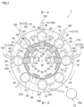
- FIG. 1 is a side elevational view of a printing device 1.
- the printing device 1 is provided with a can body supply part 510 to which can bodies 10 are supplied.
- the can body 10 is attached (supplied) to a support member 20 supporting the can body 10.
- the support member 20 is formed into a cylindrical shape and is inserted into the cylindrically-shaped can body 10; thereby the can body 10 is attached to the support member 20.
- FIG. 2 is a cross-sectional view of the printing device 1 along the II-II line in FIG. 1 . Note that, in FIG. 2 , illustration of part of members shown in FIG. 1 is omitted.
- a can body moving mechanism 100 as an example of a can body moving unit that moves the can body 10 is provided on the backside of the printing device 1.
- the can body moving mechanism 100 moves the can body 10 so that the can body 10 is moved around a predetermined center 30 (hereinafter, simply referred to as "center 30") (refer to FIG. 1 ). In addition, the can body moving mechanism 100 stops the can body 10 at each of plural stop points 40 (refer to FIG. 1 ).
- a circular-disk-shaped rotation member 110 rotating around the center 30 as the rotation center is provided as shown in FIGS. 1 and 2 .
- plural support members 20 are supported by the rotation member 110.
- the plural support members 20 are disposed in the state of being arranged in the circumferential direction of the rotation member 110.
- the can body moving mechanism 100 is provided with a first motor M1 that rotates the rotation member 110.
- a second motor M2 is provided to correspond to each of the support members 20 to rotate the support member 20 (the can body 10) in the circumferential direction.
- the rotation control of the first motor M1 is performed by a not-shown controller to rotate the rotation member 110 intermittently.
- the rotation member 110 rotates intermittently; accordingly, movement of the can body 10 and a stop of the can body 10 at the stop point 40 are performed repeatedly.
- rotation of the rotation member 110 moves the can body 10 (the support member 20) along a predetermined annular route R (hereinafter, sometimes referred to as "can body moving route R1 ”) (see FIG. 1 ).
- rotation of the rotation member 110 moves the can body 10 around the center 30.
- the can body 10 moves along the annular route does not mean that the can body 10 moves along all over the annular route, but means that the can body 10 moves along part of the annular route.
- the printing device 1 With reference to FIG. 1 , the printing device 1 will be further described.
- plural printing parts 120 are provided on the downstream side of the can body supply part 510.
- Each of the printing parts 120 is provided to correspond to each stop point 40, and performs printing on the can body 10 located at the stop point 40. Consequently, in the exemplary embodiment, a print image is formed on the outer circumferential surface 10A of the can body 10.
- each of the printing parts 120 in the exemplary embodiment is configured with the so-called inkjet heads 11, and the print image is formed on the can body 10, which is located at the stop point 40 and rotating in the circumferential direction, using the inkjet printing method.
- an inkjet head 11W that ejects white ink
- an inkjet head 11C that ejects cyan ink
- an inkjet head 11M that ejects magenta ink
- an inkjet head 11Y that ejects yellow ink
- an inkjet head 11K that ejects black ink
- the five inkjet heads 11, namely, the inkjet heads 11W to 11K perform image formation on the can body 10 using ultraviolet cure ink.
- the five inkjet heads 11 perform image formation onto the can body 10 by using photo-curable ink, which cures upon being irradiated with light such as ultraviolet rays.
- the image formation by the inkjet printing method refers to image formation performed by ejecting ink from the inkjet heads 11 to attach the ink to the can body 10.
- the colors of ink ejected by the inkjet heads 11 are not limited to the above five colors, and ink of other colors may be ejected from the inkjet heads 11.
- transparent ink may be ejected from the inkjet heads 11, not limited to colored ink.
- the case in which the five inkjet heads 11 are provided is described as an example; however, the number of inkjet heads 11 to be installed is not particularly limited, and the inkjet heads 11 in the number other than five may be provided.
- plural light sources 13, as an example of curing unit, that cure the print images formed on the can bodies 10 are provided.
- the light source 13 is provided to correspond to each of the plural stop points 40. In addition, the light sources 13 are located on the side opposite to the side where the printing parts 120 are installed across the can body moving route R1.
- the light source 13 emits light of the wavelength in the ultraviolet range (hereinafter, referred to as "ultraviolet light” in some cases), as an example of light, to the can body 10 which is stopped at the stop point 40 and is rotating in the circumferential direction. This cures the print image formed on the outer circumferential surface 10A of the can body 10.
- plural shielding parts 51 that shield ultraviolet light from the respective light sources 13 are provided as shown in FIG. 1 .
- the shielding part 51 is located at the position facing the light source 13.
- the shielding part 51 is located on a route R2, through which ultraviolet light from the light source 13 to proceed toward the printing part 120 passes.
- a first annular member 50 (also refer to FIG. 2 ) is provided inside the can body moving route R1.
- the first annular member 50 is formed into an annular shape, and rotates around a point where the center 30 (refer to FIG. 1 ) is located as a rotation center.
- the first annular member 50 is disposed coaxially with the rotation member 110, and rotates around the point where the center 30 is located.
- the first annular member 50 is attached to the rotation member 110, and rotates in conjunction with the rotation member 110, as shown in FIG. 2 .
- each of the plural shielding parts 51 (refer to FIG. 1 ) is configured with part of the first annular member 50.
- the first annular member 50 is provided with passing parts 52 through which light from the light sources 13 toward the can bodies 10 stopping at the stop points 40 passes.
- the first annular member 50 is provided with the passing parts 52 for passing the light from the light sources 13 toward the can bodies 10 stopping at the stop points 40.
- the passing part 52 is configured with a through hole 50C that connects the inner circumferential surface 50A side and the outer circumferential surface 50B side of the first annular member 50.
- passing part 52 is not limited to the through hole 50C, but may be formed in other shapes such as a cutout.
- the passing part 52 provided in the first annular member 50 is located between the light source 13 and the can body 10, as shown in FIG. 1 . This allows light from the light source 13 to pass through the passing part 52 and proceed toward the can body 10.
- the print image formed on the can body 10 is irradiated with ultraviolet light to be cured.
- each of the light sources 13 is disposed closer to the center 30 than the can body moving route R1.
- the first annular member 50 (the shielding part 51) is also disposed closer to the center 30 than the can body moving route R1.
- disposition of the light source 13 closer to the center 30 than the can body moving route R1 makes it easier to reduce the light sources 13.
- the case in which the light sources 13 are provided as many as the number of stop points 40 is shown as an example; however, in the case in which the light sources 13 are disposed closer to the center 30 than the can body moving route R1, it is possible to share the light sources 13.
- the light sources 13 are disposed closer to the center 30 than the can body moving route R1
- the light sources 13 of the number smaller than the number of stop points 40 are installed, and the can body 10 at each of the stop points 40 can be irradiated with ultraviolet light by the small number of light sources 13.
- restriction parts 61 that restrict the ultraviolet light from the light sources 13 passing through the passing parts 52 and proceeding toward a side opposite to the side where the light sources 13 are installed.
- the restriction part 61 is configured with part of a second annular member 60 disposed coaxially with the first annular member 50.
- the second annular member 60 is formed into an annular shape.
- the second annular member 60 is not fixed to the rotation member 110 (refer to FIG. 2 ), but is fixed to the main body side of the printing device 1.
- the second annular member 60 is also provided with passing parts 62 through which light from the light sources 13 passes to proceed toward the can bodies 10 stopping at the stop points 40.
- the second annular member 60 is also provided with the passing parts 62 for directing the light from the light sources 13 toward the can bodies 10 stopping at the stop points 40.
- the passing part 62 is, similar to the passing part 52 provided in the first annular member 50, configured with a through hole. Note that the passing part 62 is not limited to the through hole, but may be configured with a cutout, etc.
- a detachment part 780 that detaches the can body 10 from the support member 20 is provided on the downstream side of the plural printing parts 120.
- the can body 10 is detached from the support member 20 in the detachment part 780 to be discharged to the outside of the printing device 1.
- the can body 10 discharged to the outside of the printing device 1 is conveyed sequentially to the coating process in which transparent paint is applied to the outer circumferential surface 10A of the can body 10, and to the heating process in which the can body 10 coated with the transparent paint is heated.
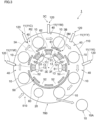
- FIG. 3 is a diagram showing a state of the printing device 1 when the can body 10 is moving. More specifically, FIG. 3 is a diagram showing the state of the printing device 1 in which each can body 10 stopped at the stop point 40 is moving toward the next stop point 40 located on the downstream side.
- the first annular member 50 is attached to the rotation member 110, and rotates in conjunction with the rotation member 110. Consequently, in the exemplary embodiment, the first annular member 50 moves synchronously with the moving plural can bodies 10.
- the first annular member 50 rotates in the state where the passing parts 52 are located at the positions facing the can bodies 10, as shown in FIG. 3 .
- each of the shielding parts 51 provided in the first annular member 50 comes to be located at the position facing the light source 13.
- the can body 10 when each of the can bodies 10 moves, the can body 10 is not located at the stop point 40 as shown in FIG. 3 , and the ultraviolet light from the light source 13 is going to proceed toward the printing part 120.
- the shielding part 51 is located at the position facing the light source 13, and accordingly, the ultraviolet light is shielded to be less likely to reach the printing part 120.
- the shielding part 51 is located between the light source 13 and the printing part 120, and thereby the ultraviolet light from the light source 13 to the printing part 120 is shielded.
- the shielding part 51 is located on the route R2, through which the ultraviolet light from the light source 13 proceeding toward the printing part 120 passes.
- the ultraviolet light is shielded, and it becomes difficult for the ultraviolet light to reach the printing part 120.
- the shielding part 51 is located at the position deviated from the position facing the light source 13, and the passing part 52 is located at the position facing the light source 13, as shown in FIG. 1 . This makes it possible to irradiate the can body 10 with the ultraviolet light from the light source 13.
- the shielding part 51 in the state in which the can body 10 is not located at the stop point 40, the shielding part 51 is located at the position facing the light source 13, and accordingly, the ultraviolet light from the light source 13 does not proceed toward the printing part 120.
- the passing part 52 of the first annular member 50 is located at the point deviated from between the light source 13 and the printing part 120 indicated by the reference sign 3C.
- the light from the light sources 13 indicated by the reference signs 3E and 3F passes through the passing part 52 located at the deviated point and is going to proceed toward a side opposite to the side where the light source 13 is installed.
- the restriction part 61 (the restriction part 61 indicated by the reference sign 3M) configured with the second annular member 60 is located at the position facing the passing part 52, and thereby the light from the light source 13, which passes the passing part 52 and proceeds toward the side opposite to the side where the light source 13 is installed, is restricted.
- the light from the light source 13 is restricted from passing through the passing part 52 and going outward in the radial direction of the first annular member 50.
- the passing part 62 is provided at the portion of the second annular member 60, which is located at the position facing the stop point 40.
- the ultraviolet light from the light source 13 proceeding toward the can body 10 located at the stop point 40 is prevented from being shielded by the second annular member 60.
- the second annular member 60 is provided with the passing part 62 while being provided with the restriction part 61; therefore, in the exemplary embodiment, it is possible to irradiate the can body 10 with the ultraviolet light while shielding the ultraviolet light passing through the passing part 52.
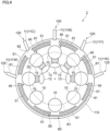
- FIG. 4 is a diagram showing another configuration example of the printing device 1.
- the configuration in which the shielding part 51 is located at the position facing the light source 13 is described; however, the configuration is not limited thereto, and a configuration in which the shielding part 51 is located at a position facing the printing part 120 may be available.
- the first annular member 50 and the second annular member 60 are provided outside the can body moving route R1.
- the shielding parts 51 are configured with the first annular member 50.
- the shielding part 51 is located at the position facing the printing part 120, to thereby prevent the ultraviolet light from the light source 13 from reaching the printing part 120.
- the restriction part 61 configured with the second annular member 60 is located at the position facing the passing part 52. This prevents the light from the light sources 13 from passing through the passing part 52 and proceeding toward a side opposite to the side where the light source 13 is installed.
- the shielding parts 51 may be located both the positions facing the light sources 13 and the positions facing the printing parts 120.
- the second annular members 60 may be provided both inside and outside the can body moving route R1, or may be provided only on one of the inside and the outside.
- first annular member 50 is provided only outside the can body moving route R1
- second annular member 60 is preferable to provide the second annular member 60 outside the can body moving route R1.
- first annular member 50 is provided only inside the can body moving route R1
- second annular member 60 is preferable to provide the second annular member 60 inside the can body moving route R1.
- one of the annular members, the first annular member 50 and the second annular member 60 is provided on one of the inside and the outside of the can body moving route R1
- the other one of the annular members, the first annular member 50 and the second annular member 60 is provided on the other one of the inside and the outside of the can body moving route R1.
- FIG. 5 is a diagram showing another configuration example of the printing device 1.
- the printing parts 120 may be provided inside the can body moving route R1, and the light sources 13 may be provided outside the can body moving route R1, as shown in FIG. 5 .
- the number of printing parts 120 installed is 4.
- positions of the can body supply part 510 and the detachment part 780 are different from the positions shown in FIG. 1 .
- first annular member 50 and the second annular member 60 are provided outside the can body moving route R1.
- the shielding part 51 is located on the route R2, through which the ultraviolet light from the light source 13 to proceed toward the printing part 120 passes.
- the shielding part 51 configured with a part of the first annular member 50 is located at the position facing the light source 13. In other words, the shielding part 51 is located between the light source 13 and the printing part 120.
- the shielding part 51 is located at the point deviated from the position facing the light source 13.
- the shielding part 51 is located at a point deviated from the route R2, through which the ultraviolet light from the light source 13 to proceed toward the can body 10 passes.
- the shielding part 51 is located at a point deviated from between the light source 13 and the printing part 120.
- the ultraviolet light from the light source 13 passes through the passing part 52 located at the point deviated from between the light source 13 and the printing part 120, and is going to proceed toward a side opposite to the side where the light source 13 is installed. More specifically, the ultraviolet light is going to proceed toward the inside of the first annular member 50.
- the restriction part 61 configured with the second annular member 60 is located at the position facing the passing part 52, and thereby the ultraviolet light from the light source 13 is prevented from passing through the passing part 52 and proceeding toward the side opposite to the side where the light source 13 is installed.
- the passing parts 62 are provided at the portions of the second annular member 60, which are positioned at the points facing the stop points 40. Consequently, the ultraviolet light from the light source 13 proceeding toward the can body 10 located at the stop point 40 is prevented from being shielded by the second annular member 60.
- the first annular member 50 is not limited to be provided outside the can body moving route R1, but may be provided inside the can body moving route R1 to cause the shielding parts 51 configured with part of the first annular member 50 to be disposed at the positions facing the printing parts 120.
- first annular members 50 are provided both inside and outside the can body moving route R1 and the shielding parts 51 configured with part of the first annular member 50 are located at both the positions facing the light sources 13 and the positions facing the printing parts 120.
- the second annular members 60 may be provided both inside and outside the can body moving route R1, or may be provided only on one of the inside and the outside.
- first annular member 50 is provided only inside the can body moving route R1
- second annular member 60 is preferable to provide the second annular member 60 inside the can body moving route R1.
- one of the annular members, the first annular member 50 and the second annular member 60 is provided on one of the inside and the outside of the can body moving route R1
- the other one of the annular members, the first annular member 50 and the second annular member 60 is provided on the other one of the inside and the outside of the can body moving route R1.
- the case providing the light source 13 emitting the ultraviolet light as an example of a curing unit, has been described as an example; however, other than this, a heat source may be provided as the curing unit. More specifically, a heat source may be provided instead of the above-described light source 13.
- the printing part 120 may use thermosetting ink, and, in this case, a heat source is provided as the curing unit.
- adoption of configurations shown in FIGS. 1 to 5 reduces heat from the heat source to the printing part 120; accordingly, defects such as ink curing in the printing part 120 caused by heat are less likely to occur.
- the printing method performed by the printing part 120 is not particularly limited, and, for example, a printing mechanism performing printing by the plate printing method may be provided as the printing part 120.
- the configuration providing the first annular member 50 inside the second annular member 60 has been described as an example; however, the second annular member 60 may be provided inside the first annular member 50.
- the shielding parts 51 have been configured using part of the first annular member 50; however, not limited thereto, a shatter-shaped shielding part 51 may be individually provided at a position facing each of the light sources 13 or the printing parts 120.
- the shutter-shaped shielding part 51 is opened and closed in accordance with the presence or absence of the can body 10 at the stop point 40.
- the passing part 52 in the first annular member 50 may be provided with a reflection member such as a lens passing the light from the light source 13 and a mirror reflecting the light from the light source 13 toward the can body 10.
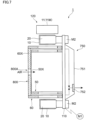
- FIGS. 6 and 7 are diagrams showing other configuration examples of the printing device 1.
- FIG. 7 shows a cross-sectional view along the VII-VII line in FIG. 6 .
- FIG. 6 shows a case in which a heat source 130 is provided in place of the above-described light source 13 as an example.
- illustration of the heat source 130 is omitted.
- plural gaps 90G extending in the circumferential direction of the first annular member 50 are provided between the first annular member 50 and the second annular member 60.
- a closing part 90N is provided to correspond to each of the gaps 90G, the closing part 90N closing one of two openings 90M of the gap 90G.
- the closing part 90N is supported by the first annular member 50.
- a circular-disk-shaped closing member 800 that closes an opening 50X located at an end portion the first annular member 50 and an opening 60X located at an end portion the second annular member 60.
- the closing member 800 is attached to the second annular member 60.
- the closing member 800 is provided with an air intake port 800A for taking in the air outside the second annular member 60 into the inside of the second annular member 60.
- a through hole 97 is formed at a portion of the rotation member 110 that faces each of the gaps 90G. Furthermore, as shown in FIG. 7 , on a side opposite to the side, across the rotation member 100, where the gap 90G (refer to FIG. 6 ) is provided, a suction mechanism 750 that sucks the air inside the gap 90G via the through hole 97 (refer to FIG. 6 ) is installed.
- the suction mechanism 750 is provided with a fan (not shown), a housing 751 that houses the fan, and a filter 752 that allows the air to be discharged from the housing 751 (the air drawn out of the gap 90G) to pass through.
- gases such as solvents and water vapors are generated from the print image, and the gases accumulate in the first annular member 50 and the second annular member 60.
- the suction mechanism 750 is provided as described above; accordingly, the gases in the first annular member 50 and the second annular member 60 are discharged through the through hole 97 to the outside of the first annular member 50 and the second annular member 60.
- the gases generated from the print image enter inside the gap 90G from a position facing each can body 10, as indicated by the arrow 6X in FIG. 6 .
- the gases are then discharged via the through hole 97 to the outside of the first annular member 50 and the second annular member 60.
- the gases generated from the print image are discharged to the outside of the printing device 1 through the gaps 90G and the through holes 97.
- the gases pass through the filter 752 provided in the suction mechanism 750.
- the gases near the surface of the can body 10 can be discharged to the outside of the first annular member 50 and the second annular member 60 more efficiently, as compared to the case where the gases inside the first annular member 50 and the second annular member 60 are discharged without the gaps 90G.
- the first annular member 50 is provided inside the second annular member 60 and the gaps 90G are provided between the first annular member 50 and the second annular member 60 was described; however, not limited thereto, the second annular member 60 may be provided inside the first annular member 50, and then the gaps 90G may be provided between the first annular member 50 and the second annular member 60.
- the gaps 90G may be formed, and the gases inside the first annular member 50 and the second annular member 60 may be discharged through the gaps 90G in a similar manner.
Landscapes
- Health & Medical Sciences (AREA)
- General Health & Medical Sciences (AREA)
- Toxicology (AREA)
- Engineering & Computer Science (AREA)
- Manufacturing & Machinery (AREA)
- Ink Jet (AREA)
- Coating Apparatus (AREA)
Applications Claiming Priority (2)
| Application Number | Priority Date | Filing Date | Title |
|---|---|---|---|
| JP2020172083A JP7470612B2 (ja) | 2020-10-12 | 2020-10-12 | 印刷装置 |
| PCT/JP2021/033711 WO2022080065A1 (fr) | 2020-10-12 | 2021-09-14 | Dispositif d'impression |
Publications (3)
| Publication Number | Publication Date |
|---|---|
| EP4227008A1 true EP4227008A1 (fr) | 2023-08-16 |
| EP4227008A4 EP4227008A4 (fr) | 2024-04-24 |
| EP4227008B1 EP4227008B1 (fr) | 2026-01-07 |
Family
ID=81208343
Family Applications (1)
| Application Number | Title | Priority Date | Filing Date |
|---|---|---|---|
| EP21879807.2A Active EP4227008B1 (fr) | 2020-10-12 | 2021-09-14 | Dispositif d'impression |
Country Status (5)
| Country | Link |
|---|---|
| US (1) | US20230373227A1 (fr) |
| EP (1) | EP4227008B1 (fr) |
| JP (1) | JP7470612B2 (fr) |
| CN (1) | CN116033970A (fr) |
| WO (1) | WO2022080065A1 (fr) |
Families Citing this family (2)
| Publication number | Priority date | Publication date | Assignee | Title |
|---|---|---|---|---|
| JP7820117B2 (ja) * | 2021-09-28 | 2026-02-25 | アルテミラ・ホールディングス株式会社 | 画像形成装置 |
| JP7588385B1 (ja) | 2024-04-25 | 2024-11-22 | 有限会社中田スクリーン印刷 | 印刷機及び印刷方法 |
Family Cites Families (17)
| Publication number | Priority date | Publication date | Assignee | Title |
|---|---|---|---|---|
| US4750419A (en) * | 1986-03-24 | 1988-06-14 | Meredith Steven A | Process and a machine for printing on articles by silk screening |
| US5667850A (en) * | 1996-10-04 | 1997-09-16 | Gavenco, Llc | Method of curing with ultraviolet radiation on substrates requiring low heat |
| US5970865A (en) * | 1997-02-26 | 1999-10-26 | Mitsubishi Materials Corporation | Apparatus and method for printing multi-color images onto cylindrical body |
| DE10226500B4 (de) | 2002-06-14 | 2010-04-22 | Ball Packaging Europe Holding Gmbh & Co. Kg | Vorrichtung zur Oberflächenbearbeitung von Teilen |
| DE10349560A1 (de) * | 2003-10-22 | 2005-06-02 | Werner Kammann Maschinenfabrik Gmbh | Vorrichtung zum Dekorieren von formsteifen Objekten |
| ES2300912T3 (es) * | 2005-08-20 | 2008-06-16 | Hinterkopf Gmbh | Maquina para imprimir cuerpos huecos. |
| ITRE20060016A1 (it) * | 2006-02-10 | 2007-08-11 | Omso Officina Macchine Per Stampa Su Oggetti | Macchina di stampa serigrafica per oggetti cilindrici |
| WO2012149187A1 (fr) * | 2011-04-26 | 2012-11-01 | Lacaze John R | Appareils d'impression sur des objets généralement cylindriques et procédés associés |
| DE102013208065A1 (de) * | 2013-05-02 | 2013-07-04 | Krones Ag | Rundläufermaschine zur Bedruckung von Behältern |
| DE102013217659A1 (de) * | 2013-09-04 | 2015-03-05 | Krones Ag | Behälterbehandlungsmaschine zur Bedruckung von Behältern |
| CN105593031A (zh) * | 2013-10-04 | 2016-05-18 | 宝洁公司 | 用于装饰制品的工艺 |
| JP6530273B2 (ja) * | 2015-08-05 | 2019-06-12 | 昭和アルミニウム缶株式会社 | 印刷装置 |
| JP6581840B2 (ja) * | 2015-08-11 | 2019-09-25 | 昭和アルミニウム缶株式会社 | 飲料用缶、飲料用缶の製造方法および画像形成システム |
| JP6809916B2 (ja) | 2016-04-28 | 2021-01-06 | 昭和アルミニウム缶株式会社 | 印刷装置 |
| JP7240165B2 (ja) * | 2018-12-18 | 2023-03-15 | アルテミラ株式会社 | 印刷システム |
| JP7573360B2 (ja) | 2019-03-22 | 2024-10-25 | アルテミラ株式会社 | 印刷システム |
| CN110202949B (zh) * | 2019-05-08 | 2024-07-16 | 广州诺彩数码产品有限公司 | 一种用于在圆弧面上打印的装置 |
-
2020
- 2020-10-12 JP JP2020172083A patent/JP7470612B2/ja active Active
-
2021
- 2021-09-14 EP EP21879807.2A patent/EP4227008B1/fr active Active
- 2021-09-14 US US18/024,970 patent/US20230373227A1/en not_active Abandoned
- 2021-09-14 WO PCT/JP2021/033711 patent/WO2022080065A1/fr not_active Ceased
- 2021-09-14 CN CN202180051495.9A patent/CN116033970A/zh active Pending
Also Published As
| Publication number | Publication date |
|---|---|
| WO2022080065A1 (fr) | 2022-04-21 |
| EP4227008A4 (fr) | 2024-04-24 |
| US20230373227A1 (en) | 2023-11-23 |
| JP7470612B2 (ja) | 2024-04-18 |
| CN116033970A (zh) | 2023-04-28 |
| EP4227008B1 (fr) | 2026-01-07 |
| JP2022063702A (ja) | 2022-04-22 |
Similar Documents
| Publication | Publication Date | Title |
|---|---|---|
| EP4227008B1 (fr) | Dispositif d'impression | |
| CN111278654B (zh) | 印刷装置 | |
| CN107848295B (zh) | 印刷装置 | |
| US11090960B2 (en) | Posture adjusting apparatus and inkjet image forming apparatus | |
| JP6643852B2 (ja) | 印刷装置 | |
| CN108778750A (zh) | 印刷装置 | |
| CN111278653B (zh) | 印刷装置 | |
| JP6530273B2 (ja) | 印刷装置 | |
| EP3901048B1 (fr) | Système d'impression | |
| EP3943306B1 (fr) | Système d'impression | |
| EP4227101B1 (fr) | Dispositif d'impression | |
| CN112703114B (zh) | 印刷系统以及罐体的制造方法 | |
| JP6637266B2 (ja) | 印刷装置 | |
| JP6647815B2 (ja) | 印刷装置 | |
| KR102560818B1 (ko) | 노광 장치 | |
| JP2008173884A (ja) | 記録装置 |
Legal Events
| Date | Code | Title | Description |
|---|---|---|---|
| STAA | Information on the status of an ep patent application or granted ep patent |
Free format text: STATUS: THE INTERNATIONAL PUBLICATION HAS BEEN MADE |
|
| PUAI | Public reference made under article 153(3) epc to a published international application that has entered the european phase |
Free format text: ORIGINAL CODE: 0009012 |
|
| STAA | Information on the status of an ep patent application or granted ep patent |
Free format text: STATUS: REQUEST FOR EXAMINATION WAS MADE |
|
| 17P | Request for examination filed |
Effective date: 20230320 |
|
| AK | Designated contracting states |
Kind code of ref document: A1 Designated state(s): AL AT BE BG CH CY CZ DE DK EE ES FI FR GB GR HR HU IE IS IT LI LT LU LV MC MK MT NL NO PL PT RO RS SE SI SK SM TR |
|
| DAV | Request for validation of the european patent (deleted) | ||
| DAX | Request for extension of the european patent (deleted) | ||
| REG | Reference to a national code |
Ref legal event code: R079 Ref country code: DE Ref legal event code: R079 Ref document number: 602021046139 Country of ref document: DE Free format text: PREVIOUS MAIN CLASS: B05C0009120000 Ipc: B41J0003407000 |
|
| A4 | Supplementary search report drawn up and despatched |
Effective date: 20240321 |
|
| RIC1 | Information provided on ipc code assigned before grant |
Ipc: B05C 13/02 20060101ALN20240315BHEP Ipc: B41J 11/00 20060101ALI20240315BHEP Ipc: B41J 3/407 20060101AFI20240315BHEP |
|
| GRAP | Despatch of communication of intention to grant a patent |
Free format text: ORIGINAL CODE: EPIDOSNIGR1 |
|
| STAA | Information on the status of an ep patent application or granted ep patent |
Free format text: STATUS: GRANT OF PATENT IS INTENDED |
|
| RIC1 | Information provided on ipc code assigned before grant |
Ipc: B41J 3/407 20060101AFI20250918BHEP Ipc: B41J 11/00 20060101ALI20250918BHEP Ipc: B05C 13/02 20060101ALN20250918BHEP |
|
| INTG | Intention to grant announced |
Effective date: 20250930 |
|
| P01 | Opt-out of the competence of the unified patent court (upc) registered |
Free format text: CASE NUMBER: UPC_APP_0010381_4227008/2025 Effective date: 20251020 |
|
| GRAS | Grant fee paid |
Free format text: ORIGINAL CODE: EPIDOSNIGR3 |
|
| GRAA | (expected) grant |
Free format text: ORIGINAL CODE: 0009210 |
|
| STAA | Information on the status of an ep patent application or granted ep patent |
Free format text: STATUS: THE PATENT HAS BEEN GRANTED |
|
| AK | Designated contracting states |
Kind code of ref document: B1 Designated state(s): AL AT BE BG CH CY CZ DE DK EE ES FI FR GB GR HR HU IE IS IT LI LT LU LV MC MK MT NL NO PL PT RO RS SE SI SK SM TR |
|
| REG | Reference to a national code |
Ref country code: CH Ref legal event code: F10 Free format text: ST27 STATUS EVENT CODE: U-0-0-F10-F00 (AS PROVIDED BY THE NATIONAL OFFICE) Effective date: 20260107 Ref country code: GB Ref legal event code: FG4D |
|
| REG | Reference to a national code |
Ref country code: DE Ref legal event code: R096 Ref document number: 602021046139 Country of ref document: DE |
|
| REG | Reference to a national code |
Ref country code: DE Ref legal event code: R081 Ref document number: 602021046139 Country of ref document: DE Owner name: ALTEMIRA HOLDINGS CO., LTD., JP Free format text: FORMER OWNER: ALTEMIRA CO., LTD., TOKYO, JP |
|
| REG | Reference to a national code |
Ref country code: IE Ref legal event code: FG4D |