EP4227124B1 - Ensemble fenêtre - Google Patents
Ensemble fenêtre Download PDFInfo
- Publication number
- EP4227124B1 EP4227124B1 EP22425005.0A EP22425005A EP4227124B1 EP 4227124 B1 EP4227124 B1 EP 4227124B1 EP 22425005 A EP22425005 A EP 22425005A EP 4227124 B1 EP4227124 B1 EP 4227124B1
- Authority
- EP
- European Patent Office
- Prior art keywords
- gasket
- glazing
- window assembly
- reinforcing
- bracket
- Prior art date
- Legal status (The legal status is an assumption and is not a legal conclusion. Google has not performed a legal analysis and makes no representation as to the accuracy of the status listed.)
- Active
Links
Images


Classifications
-
- B—PERFORMING OPERATIONS; TRANSPORTING
- B60—VEHICLES IN GENERAL
- B60J—WINDOWS, WINDSCREENS, NON-FIXED ROOFS, DOORS, OR SIMILAR DEVICES FOR VEHICLES; REMOVABLE EXTERNAL PROTECTIVE COVERINGS SPECIALLY ADAPTED FOR VEHICLES
- B60J1/00—Windows; Windscreens; Accessories therefor
- B60J1/08—Windows; Windscreens; Accessories therefor arranged at vehicle sides
- B60J1/10—Windows; Windscreens; Accessories therefor arranged at vehicle sides fixedly mounted
-
- B—PERFORMING OPERATIONS; TRANSPORTING
- B60—VEHICLES IN GENERAL
- B60J—WINDOWS, WINDSCREENS, NON-FIXED ROOFS, DOORS, OR SIMILAR DEVICES FOR VEHICLES; REMOVABLE EXTERNAL PROTECTIVE COVERINGS SPECIALLY ADAPTED FOR VEHICLES
- B60J1/00—Windows; Windscreens; Accessories therefor
- B60J1/004—Mounting of windows
- B60J1/006—Mounting of windows characterised by fixation means such as clips, adhesive, etc.
-
- B—PERFORMING OPERATIONS; TRANSPORTING
- B60—VEHICLES IN GENERAL
- B60J—WINDOWS, WINDSCREENS, NON-FIXED ROOFS, DOORS, OR SIMILAR DEVICES FOR VEHICLES; REMOVABLE EXTERNAL PROTECTIVE COVERINGS SPECIALLY ADAPTED FOR VEHICLES
- B60J10/00—Sealing arrangements
- B60J10/70—Sealing arrangements specially adapted for windows or windscreens
-
- B—PERFORMING OPERATIONS; TRANSPORTING
- B61—RAILWAYS
- B61D—BODY DETAILS OR KINDS OF RAILWAY VEHICLES
- B61D23/00—Construction of steps for railway vehicles
Definitions
- the present invention refers to a window assembly used, for instance, in a vehicle or building or, for instance, in a train or a car. More especially the invention could be used, for instance, as a side window installed in a high-speed passenger-train.
- Lateral cab and body side windows for high capacity means of transportation, for instance, buses, trains, and metro are designed for services in a wide range of environmental and operational conditions.
- a glazing either a single pane laminated safety glass unit (LGU) or a double pane insulated glazing unit (IGU) connected to the main structural body by a metallic frame.
- LGU single pane laminated safety glass unit
- IGU double pane insulated glazing unit
- the metallic frame is replaced increasingly by an extruded circumferential structural gasket that has structural properties in order to withstand defined static and dynamic loads caused by the operating conditions like, for instance, aerodynamic pressures, inertial forces due to acceleration or impacts/crashes, human loads and different combination of the mentioned actions in the spatial directions.
- DE 28 20 620 A1 describes an elastic sealing and fixing strip, especially for a windscreens in a motor vehicle bodywork.
- the windscreen is located in a window opening, formed by a flange rim of a motor vehicle body, and is sealed and held by a sealing and fixing strip that has a receiving groove corresponding to the thickness of the windscreen.
- the sealing and fixing strip can be provided with an L-shaped support strip 15 that surrounds the front edge of the groove which receives the windscreen.
- US 2 575 854 relates to the field of rail vehicles and provides a double glass sash construction used in windows of air-conditioned railway cars.
- the sash construction has a pair of generally rectangular rim members forming a frame having a channel-like recess for receiving and clamping the edges of the glass panes, fasting elements to hold the rim members in clamping position, and resilient separator and glazing strips positioned at the edges of the panes from each other and from the rim members.
- US 4 591 203 describes a vehicle body that has a window opening defined by a peripheral pinchweld flange which includes a plurality of slots.
- the window opening is closed by a modular rear quarter window assembly of the type having a glass window panel which has a molded PVC frame formed around its peripheral edge.
- the structural gasket presents significant advantages towards traditional solutions based on metallic frames coupling glazing and body structure.
- the main advantages of the structured gasket made of polymeric material are, for instance, the elimination of heavy and expensive parts like the metallic frame itself.
- the main problem of the structural gasket is related to the need of structural consistency of the gasket in transferring of comparable mechanical stress and loads from the glazing to the body structure and vice versa.
- a further remarkable advantages of the window assembly of the present invention due to the reinforcing device are lower weight than with standard solution, easier assembly and maintenance of the system glazing/gasket on the vehicle's body, better fitting on the subcomponents with improvement of the water tightness of the system and less design constraint due to a lighter profile of the gasket that is more elastic and, therefore, can fit better the curvature of the glazing, improved overall mechanical strength and fatigue performances.
- the window assembly of the invention has a reinforcing device that is fixed or at least partly moveable during installing or mounting the glazing on the body.
- the moveable reinforcing device allows that the window can withstand even strongly increased loads.
- the window assembly of the invention can comprise an improved reinforcing device with a bracket comprising a number of fixing through holes or fixing bores which are defined by means of corresponding sockets or sleeves extending from a glass gap between parallel glass panes through fixing through holes beyond the glazing edge face or edge of the glazing into the gasket.
- This preferred construction allows a reinforcing of the gasket and, thus, it also contributes to an increased mechanical resistance of the whole window assembly.
- the window assembly of the invention provides at least one reinforcing member of the reinforcing device which is moveable or pivotable from a mounting position to a locked position in order to improve the mechanical resistance of the window assembly.
- this feature allows a comfortable mounting of the reinforcing device or reinforcing member, particularly if the reinforcing member occupies a substantial part of the cross section area in the body recess between the inside and outside parallel walls of the profiled edge of the body.
- the gasket inner wall portion and/or the gasket outer wall portion comprise(s) at least one moveable portion that is connected or coupled to the gasket in a hinged or folding manner, wherein, during mounting of the glazing, the moveable portion is in an opened position for allowing access to the moveable reinforcing member(s) of the reinforcing device to be able to move the moveable reinforcing member(s) from a mounting position into a locked position, and wherein, after moving the reinforcing member(s), the moveable portion is pushed into a closed position in which the access to the moveable reinforcing member(s) is closed and the moveable portion of the gasket touches the body surface.
- the window assembly of the invention can provide at least one bore or hole in the bracket, the equalizing strip and a corresponding bore or hole in a middle portion of the gasket, whereby the respective insert extends in the bore of the lining layer and in the corresponding bore of the middle portion of the gasket to ensure a secure seat of the insert and, accordingly, a corresponding reinforcement of the gasket.
- the window assembly could provide a gasket that has a gasket inner wall portion or inner web, a gasket outer wall portion or outer web, and a gasket intermediate portion extending between gasket inner and outer wall portions, wherein the gasket inner wall portion extends on an inner surface of the glazing and on inner body surface of the body, the gasket outer wall portion extends on an outer surface of the glazing and on an outer body surface of the body, and wherein the gasket intermediate portion extending between the bracket and the equalizing strip of the reinforcing device in order to reinforce the gasket and to enable a strong and sufficient fixing of the reinforcing device on the gasket and at the vehicle body.
- the window assembly or reinforcing device of the invention may have several inserts, pins or screws arranged along a perimeter or circumference of the gasket for improving the mechanical resistivity of the window assembly against increased mechanical loads effecting on the window assembly.
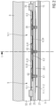
- Fig. 1 shows a schematic section part-view of a window assembly 10 according to a preferred and exemplified embodiment of the invention comprising a reinforcing device 6 for a gasket 4 wherein the reinforcing device 6 is in a locked position.
- the window assembly 10 is shown in the assembled state with a glazing 1 mounted in a circumferential gasket 4 that extends on a circumferential opening edge face 5 of a body 8, for instance, of a vehicle or building, defining a window opening 7.
- the reinforcing device 6 is in a locked position.
- the window assembly 10 could also be used, for instance, as a side window of a high-speed passenger train.
- the glazing 1 of the window assembly 10 comprises two glass panes 2, 3 arranged parallel and a circumferential glazing edge face 11 or edge faces.
- the glazing 1 is arranged within the window opening 7 of the body 8.
- the glazing 1 of the window assembly 10 may be an insulating glazing comprising, for instance, two usually transparent and parallel glass panes, an inner glass pane 2 and an outer glass pane 3.
- the glazing 1 may be a double pane insulated glazing unit (IGU) coupled to the main structural body 8 by the gasket 4.
- the inner and outer glass panes 2 and 3 are separated by a dehydrated gas gap 26 enclosing, for instance, air or a special inert gas.
- the glass panes 2 and 3 can be made of monolithic tempered glass or laminated safety glass.
- a circumferential insolating spacer 27 is arranged and glued in between the inner and outer glass panes 2 and 3.
- a remaining circumferential gap 26.1 or glazing recess is provided above the spacer 27 between the glass panes 2 and 3.
- the outer glass pane 3 of the glazing 1 has an outer surface 3.1 corresponding to an outer surface 3.1 of the glazing 1 which is directed to an outside or environment of the respective vehicle or building.
- the inner glass pane 2 of the glazing 1 has an inner surface 2.1 corresponding to an inner surface 2.1 of the glazing 1 which is directed to an inside of the respective vehicle or building.
- the opening edge face 5 or edge of the body 8 is profiled and comprises a circumferential body recess 9 or holding fixture opened to the window opening 7.
- the recess 9 of the body 8 is defined by a circumferential inner wall 51 and a circumferential outer wall 52 extending in parallel wherein the inner wall 51 of the body 8 has an inner vehicle surface 53 directed to the inside or passenger side of the vehicle or building and the inner wall 52 of the body 8 has an inner body surface 54 directed to an outside or environmental side of the vehicle or building.
- the walls 51 and 52 are flush at the opening edge face 5 of the body 8.
- the window assembly 10 of Fig. 1 comprises a reinforcing device 6 for reinforcing the gasket 4.
- the reinforcing device 6 could comprise a bracket 29, at least one insert 6.1 or several inserts 6.1, a mounting or equalizing strip 6.2 that is flat and even and that is parallel to the opening edge face 5 of the body 8 and to the glazing edge face 11 if the window assembly 10 is readily installed or mounted, and at least one moveable reinforcing member 6.3 or several moveable reinforcing members 6.3 extending in the body recess 9 of the body 8 if they are in locked position.
- the reinforcing device could be formed circumferentially like a continuous frame comprising a circumferential bracket along the outer glazing edge face 11 of the glazing 1 or the reinforcing device may be formed in a single unit or separate units comprising one or more separated brackets 29 that are arranged with equal or unequal distance along the circumferential glazing edge face 11 of the glazing 1 or there could be a single bracket 29 arranged on the glazing edge face 11 of Fig.1 and Fig. 4 .
- the bracket 29 is arranged or glued on the glazing edge face 11 or edge faces of the inner and outer glass panes 2 and 3.
- the bracket 29 has a flat covering portion 29.1 arranged on the glazing edge face 11 and covering the circumferential gap 26.1 of the glazing 1 partly, an outside portion 29.3 extending on the outer surface 3.1 of the outer glass pane 3, and an inside portion 29.2 extending on the inner surface 2.1 of the inner glass pane 2.
- the inside and outside portions 29.2 and 29.3 are substantially normal to the covering portion 29.1 of the bracket 29 and they are parallel to the inner and outer surfaces 2.1 and 3.1 of the glass panes 2 and 3.
- the bracket 29 comprises fixing through holes 29.4 or fixing bores which could be threaded and which are defined by means of corresponding hollow sockets 29.5 or sleeves, that could be threaded, extending from the circumferential gap 26.1 above the spacer 27 between the glass panes 2 and 3 through the fixing through holes 29.4 beyond the glazing edge face 11 of the glazing 1 into the covering portion 29.1 of the bracket 29 of the gasket 4.
- the sockets 29.5 and the fixing through holes 29.4 are provided normal to the covering portion 29.1.
- the bracket 29 may comprise three fixing through holes 29.4 or fixing bores which are defined by means of corresponding three hollow sockets 29.5 or sleeves.
- the covering portion 29.1 of the bracket 29 is arranged in corresponding equalizing recesses 11.1 and 11.2 provided on the glazing edge face 11 or edge faces of the glass panes 3 and 2, respectively, of the glazing 1 for equalizing a thickness of the covering portion 29.1 such that the covering portion 29.1 is flush to the remaining original glazing edge face 11.
- the equalizing recesses 11.1 and 11.2 could be formed by grinding/milling, 3D printing, extrusion, or molding.
- the bracket 29 can be formed integrally and could be made of composite materials, polymeric or plastic materials and/or preferably metallic materials, for instance, aluminum or stainless steel.
- Each of the moveable reinforcing members 6.3 - as shown in Figs. 3 and 4 there may be three moveable reinforcing members 6.3 - comprises an outer bar 6.31 and an inner bar 6.32 which are parallel to each other, and a flat intermediate member 6.33 extending between the outer and inner bars 6.31 and 6.32 and connecting them.
- the outer bar 6.31 has a bar outside 6.35 and the inner bar 6.32 has a bar outside 6.36 being tapered towards the intermediate member 6.33 at their free ends 6.34.
- the outer bar 6.31 has a hinged end 6.39 which is coupled to an additional flat member 6.40 which is screwed on the equalizing strip 6.2.
- the flat member 6.40 comprises a hinge socket 6.41 to be coupled to the hinged end 6.39 or a hinge pin of the hinged end 6.39 of the outer bar 6.31.
- Each intermediate member 6.33 comprises a stop 6.42 that stops at the corresponding flat member 6.40 if the corresponding moveable reinforcing member 6.3 is in the locked position.
- the stop 6.42 supports and locks the intermediate member 6.33 on the flat member 6.40.
- the moveable reinforcing members 6.3 are made of composite materials, polymeric or plastic materials, and/or preferably metallic materials, for instance, aluminium or stainless steel.
- the hinge socket 6.41 and the hinged end 6.39 or pin resulting in a hinge allow that the moveable reinforcing member(s) 6.3 can be moved or can pivot from a mounting or horizontal position, in which the moveable reinforcing member 6.3 is arranged parallel to the equalizing strip 6.2, to an upright or vertical position in which the moveable reinforcing member 6.3 is normal to the equalizing strip 6.2 in the locked position.
- a mounting or horizontal position in which the moveable reinforcing member 6.3 is arranged parallel to the equalizing strip 6.2
- the moveable reinforcing member 6.3 supports the walls 51 and 52 within the body recess 9 of the profiled body 8. A distance between the walls 51 and 52 within the body recess 9 corresponds, therefore, substantially to a distance between the bar outsides 6.35 and 6.36 of the moveable reinforcing member 6.3 for reinforcing the gasket 4 in the locked position of the moveable reinforcing member 6.3.
- the reinforcing members 6.3 in the locked position allow that the gasket 4 is able to withstand substantially increased static and dynamic loads and forces on the window assembly 10 or window.
- the moveable reinforcing member 6.3 in locking position may occupy a substantial part of the cross section area of the body recess 9 which is the cross section area between the inside and outside parallel walls 51, 52 of the profiled edge of the body 8.
- the reinforcing member 6.3 can occupy ca. 80% of the cross section area of the body 8.
- the window assembly 10 provides several structural elements or inserts 6.1 of the in the form of rotational symmetrical pins or screws for reinforcing the gasket 4, wherein the inserts 6.1 extend substantially in the gasket 4.
- Three inserts 6.1 are shown in Fig. 2 .
- Each insert 6.1 comprises a flanged head 62 and a cylindrical portion 63 extending from the flanged head 62 into the corresponding socket 29.5 of the bracket 29 in order to fix the insert 6.1 in the socket 29.5.
- the inserts 6.1 are made of composite materials, polymeric or plastic materials and/or preferably metallic materials, for instance, aluminum or stainless steel.
- the window assembly 10 of Fig. 1 comprises the circumferential frame like structural gasket 4 provided between the glazing 1 and the opening edge face 5 of the body 8.
- the gasket 4 couples or connects the glazing 1 to the body 8 and it holds the glazing 1 within the window opening 7 on the body 8 by holding the opening edge face 5 or edge of the body 8 and the outer glazing edge face 11 or edge of the glazing 1.
- the structural gasket 4 is a separate element made by a compression moulding process using polymeric extruded material.
- the structural gasket 4 is duly fitted to the glazing 1 and to the body 8.
- the gasket 4 comprises structural elastic properties in order to withstand defined static and dynamic loads on the window assembly 10 or window caused by the operating conditions like, for instance, aerodynamic uniformly distributed pressures up to 3kPa, inertial forces due to acceleration or impacts/crashes up to 5g, human loads and different combination of the mentioned actions in the spatial directions.
- the other function of the circumferential structural gasket 4 is to guarantee water tightness of the window assembly 10 in the operational conditions and last but not least a mandatory requirement is the fire/smoke opacity and toxicity compliance, for instance, according to EN 45545.
- the circumferential frame like structural gasket 4 of the window assembly 10 comprises a circumferential recess 14 for holding the glazing 1 wherein the glazing edge face 11 or edge of the glazing 1 extends within the recess 14 of the gasket 4.
- the recess 14 of the gasket 4 provides a circumferential bottom 15 that is opposed to the circumferential glazing edge face 11 of the glazing 1.
- the covering portion 29.1 of the bracket 29 extends between the bottom 15 of the recess 14 of the gasket 4 and the glazing edge face 11 of the glazing 1.
- the circumferential peripheral gasket 4 of the window assembly 10 according to the invention shown in Fig. 1 comprises a circumferential gasket outer wall portion 23 or outer web, a circumferential gasket inner wall portion 24 or inner web, and a circumferential flat gasket intermediate portion 25.
- the gasket outer wall portion 23 extends from the outer surface 3.1 of the outer glass pane 3 of the insulating glazing 1 to the outer surface 54 of the body 8 and it presses against these surfaces 3.1 and 54.
- the gasket inner wall portion 24 of the gasket 4 extends between the inner surface 2.1 of the inner glass pane 2 of the insulating glazing 1 to the inner body surface 53 of the body 8 and it presses against these surfaces 2.1 and 53.
- the gasket inner wall portion 24 or inner web can be an integral portion of the gasket 4.
- the gasket inner wall portion 24 could comprise a separate portion that is fixed to the gasket 4 after mounting of the glazing 1.
- the gasket inner wall portion 24 could comprise at least one moveable portion 24.1 that is connected or coupled to the gasket 4 in a hinged or folding manner. During mounting of the glazing 1, the moveable portion 24.1 is in an opened position for allowing access to the moveable reinforcing member(s) 6.3 of the reinforcing device 6 to be able to move the moveable reinforcing member(s) 6.3 from a mounting position into a locking position.
- the moveable portion 24.1 After moving the reinforcing member(s) 6.3, the moveable portion 24.1 is pushed into a closed position in which the access to the moveable reinforcing member(s) is closed and the moveable portion 24.1 of the gasket 4 touches the inner body surface 53 of the inner wall 51.
- the moveable portion 24.1 is indicated by a schematic separating auxiliary line s shown in Fig. 1 with the moveable portion 24.1 in its closed position after mounting of the glazing 1.
- the gasket intermediate portion 25 extends between the covering portion 29.1 of the bracket 29 and the equalizing strip 6.2 of the reinforcing device 6.
- the gasket 4 has a number of through holes 20 or bores corresponding to the number of inserts 6.1 or pins.
- Each of the through holes 20 is provided in the gasket intermediate portion 25 between a bottom 15 of a recess 14 directed to the glazing 1 and a further bottom 15.1 of a further recess 14.1 of the gasket 4 which is directed to the body 8.
- the hollow sockets 29.5 of the bracket 29 extend within the through holes 20 of the gasket intermediate portion 25.
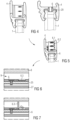
- Fig. 4 shows schematic views of the window assembly 10 of the invention according to Figs. 1 to 3 for explaining a window gasket pre-assembly wherein the gasket 4 is mounted on the bracket 29 of the reinforcing device 6.
- the bracket 29 of the reinforcing device 6 is glued on the glazing edge face 11 within the inner and outer equalizing recesses 11.1 and 11.2 such that the covering portion 29.1 of the bracket 29 is flush to the remaining not grinded original glazing edge face 11.
- the gasket 4 is arranged on the glazing edge face 11 and on the bracket 29 within the of the equalizing recesses 11.1 and 11.2 of the glazing 1 wherein the bottom 15 of the gasket 4 within the gasket recess 14 lies on the glazing edge face 11 and above the covering portion 29.1 of the bracket 29. Accordingly, the gasket outer wall portion 23 touches the outer surface 3.1 of the outer glass pane 3 and the gasket inner wall portion 24 of the bracket 29 touches the inner surface 2.1 of the inner glass pane 2.
- the hollow sockets 29.5 extend within the through holes 20 of the bracket 29.
- setting blocks 70 could be used on the further bottom 15.1 of the gasket 4 as auxiliary tools for proper positioning of the glazing 1 during the installation phase.
- Fig. 5 shows a schematic view of the window assembly 10 of the invention according to Figs. 1 to 3 explaining the mounting of a liner or equalizing strip 6.2 of the reinforcing device 6 with screws as inserts 6.1 of the reinforcing device 6 on the bottom 15.1 of the recess 14.1 of the gasket 4.
- the equalizing strip 6.2 then, is arranged on the bottom 15.1 of the gasket 4 within its recess 14.1.
- the inserts 6.1 are then screwed into the hollow screw sockets 29.5 of the bracket 29 of the reinforcing device 6 until the inserts 6.1 or screws are tightened completely to fasten the equalizing strip 6.2 on the covering portion 29.3 of the bracket 29 with holding and clamping the gasket intermediate portion 25 between the equalizing strip 6.2 and the covering portion 29.3 of the bracket 29 fixedly.
- Fig. 6 shows a schematic section view of the window assembly 10 of the invention according to Figs. 1 to 3 showing the moveable reinforcing members 6.3 of the reinforcing device 6 in the mounting position.
- the flat members 6.40 together with the corresponding moveable reinforcing members 6.3 hinged thereto are then screwed on the equalizing strip 6.2. Accordingly, the moveable reinforcement members are arranged in the mounting position in which they lie on top of the moveable reinforcing members 6.3.
- the glazing 1 with gasket 4 and reinforcing device 6 in mounting position thereon is then mounted on the body 8 within the window opening 7 whereby the opening edge face 5 or edge of the body 8 engages into the gasket recess 14.1.
- Fig. 7 shows a schematic section view of the window assembly 10 of the invention according to Figs. 1 to 3 explaining the moveable reinforcing members 6.3 of the reinforcing device 6 in their locking position. Mounting of the glazing 1 with gasket 4 is performed from outside of the body 8.
- an adjustment opening 30 or access that allows to move the moveable reinforcing member(s) 6.3 of the reinforcing device 6 from the mounting position into the locking position in which the reinforcing members 6.3 are normal to the equalizing strip 6.2 and to the gasket intermediate portion 25.
- a pin like tool could be used to cause the movement or pivoting of the moveable reinforcing member(s) 6.3 into their locking position through the adjustment opening 30.
- the adjustment opening 30 or access can be closed by moving the moveable portion 24.1 of the gasket inner wall portion 24 from its opened position into its closed position in which the adjustment opening 30 or access to the moveable reinforcing member(s) 6.3 is closed and the moveable portion 24.1 of the gasket 4 touches the inner body surface 53 of the inner wall 51.
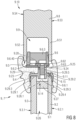
- Fig. 8 shows a schematic section part-view of a window assembly 9.10 according to a further exemplified embodiment of the invention with a fixed reinforcing device 9.6 for a gasket 9.4 wherein the reinforcing device 9.6 is in a fixed upright locking position.
- the window assembly 9.10 is shown in the assembled state with a glazing 9.1 mounted in the circumferential gasket 9.4 that extends on a circumferential opening edge face 9.5 of a body 8 or body defining a window opening 9.7.
- the window assembly 9.10 could be used, for instance, in a vehicle or a building or in a side window of a high-speed passenger train.
- the glazing 9.1 of the window assembly 9.10 comprises two glass panes 9.2, 9.3 arranged parallel and a circumferential outer glazing edge face 9.11 or edge faces.
- the glazing 9.1 is arranged within the window opening 9.7 of the body 9.8.
- the glazing 9.1 of the window assembly 9.10 may be an insulating glazing.
- the inner and outer glass panes 9.2 and 9.3 are separated by a dehydrated gas gap 9.26 enclosing, for instance, air or a special inert gas.
- a circumferential insolating spacer 9.27 is arranged and glued in between the glass panes 9.2 and 9.3.
- a remaining gap 9.26.1 or glazing recess is provided above the spacer 9.27.
- the inner glass pane 9.2 of the glazing 9.1 has an inner surface 9.2.1 which is directed to an inside of the corresponding vehicle or building.
- the outer glass pane 9.3 has an outer surface 9.3.1 which is directed to an outside or environment of the respective vehicle or building.
- the opening edge face 9.5 or edge of the body 9.8 is profiled and comprises a circumferential body recess 9.9 or holding fixture opened to the window opening 9.7.
- the recess 9.9 is defined by a circumferential inner wall 9.51 and a circumferential outer wall 9.52 extending in parallel wherein the outer wall 9.52 of the body 9.8 has an outer body surface 9.54 directed to the outside or environmental side of the vehicle or building and the inner wall 9.51 of the body 9.8 has an inner body surface 9.53 directed to an inside or passenger side of the vehicle or building.
- the walls 9.51 and 9.52 are flush to the opening edge face 9.5 of the body 8.
- the reinforcing device 9.6 could comprise a bracket 9.29, at least one insert 9.6.1 or several inserts 9.6.1, a mounting or equalizing strip 9.6.2 that is flat and even and that is parallel to the opening edge face 9.5 of the body 8 and to the glazing edge face 9.11 if the window assembly 9.10 is readily installed or mounted, and at least one locking, fixed and unmoveable reinforcing member 9.6.3 or several fixed unmoveable reinforcing members 9.6.3 extending in the body recess 9.9 of the body 9.8.
- the reinforcing device 9.6 could be formed circumferentially like a continuous frame comprising a circumferential bracket along the outer glazing edge face 9.11 of the glazing 9.1 or the reinforcing device 9.6 may be formed in a single unit or separate units comprising one or more separated brackets 9.29 that are arranged with equal or unequal distance along the circumferential glazing edge face 9.11 of the glazing 9.1 or there could be the single bracket 9.29 arranged on the glazing edge face 9.11 of Fig. 8 .
- the bracket 9.29 comprises fixing through holes 9.29.4 or fixing bores which are defined by means of corresponding hollow sockets 9.29.5.
- the sockets 9.29.5 and the fixing through holes 9.29.4 are provided normal to the covering portion 9.29.1.
- the bracket 9.29 may comprise three fixing through holes 9.29.4 or fixing bores which are defined by means of corresponding three hollow sockets 9.29.5 or sleeves.
- the bracket 9.29 can be formed integrally and could be made of composite materials, polymeric or plastic materials and/or preferably metallic materials, for instance, aluminum or stainless steel.
- the fixed reinforcing member 9.6.3 could be coupled to an additional flat member 9.6.40 which may be screwed on the equalizing strip 9.6.2 or may be mounted in upright manner on the equalizing strip 9.6.2. As shown in Fig. 8 , the reinforcing member 9.6.3 touches the inner wall 9.51 and the outer wall 9.52 within the body recess 9.9 of the profiled body 8.
- the at least one fixed reinforcing member 9.6.3 in the upright locking position allow that the gasket 9.4 is able to withstand substantially increased static and dynamic loads and forces on the window assembly 9.10 or window.
- the window assembly 9.10 provides several structural elements or inserts 9.6.1 in the form of rotational symmetrical pins or screws for reinforcing the gasket 9.4, wherein the inserts 9.6.1 extend substantially in the gasket 9.4.
- the insert 9.6.1 comprises a flanged head 9.62 and a cylindrical portion 9.63 extending from the flanged head 9.62 into the corresponding socket 9.29.5 of the bracket 9.29 in order to fix the insert 9.6.1 or screw in the socket 9.29.5.
- the at least one insert 9.6.1 is made of composite materials, polymeric or plastic materials and/or preferably metallic materials, for instance, aluminum or stainless steel.
- the window assembly 9.10 of Fig. 8 comprises the circumferential frame like structural gasket 9.4 provided between the glazing 9.1 and the opening edge face 9.5 of the body 8.
- the gasket 9.4 couples or connects the glazing 9.1 to the body 9.8 and it holds the glazing 9.1 within the window opening 9.7 on the body 9.8 by holding the opening edge face 9.5 or edge of the body 8 and the glazing edge face 9.11 or edge of the glazing 9.1.
- the circumferential frame like structural gasket 9.4 of the window assembly 9.10 comprises a circumferential recess 9.14 for accommodating and holding the corresponding glazing edge face 9.11 or edge of the glazing 9.1.
- the recess 9.14 of the gasket 9.4 provides a circumferential bottom 9.15 that is opposed to the circumferential glazing edge face 9.11 of the glazing 9.1.
- the covering portion 9.29.1 of the bracket 9.29 extends between the bottom 9.15 of the recess 9.14 of the gasket 9.4 and the glazing edge face 9.11.
- the peripheral gasket 9.4 of Fig. 8 comprises a circumferential gasket inner wall portion 9.24 or inner web, a circumferential gasket outer wall portion 9.23 or outer web, and a circumferential gasket intermediate portion 9.25.
- the gasket inner wall portion 9.24 extends from the inner surface 9.2.1 of the glazing 9.1 to the inner surface 9.53 of the body 9.8 and it presses against these surfaces 9.2.1 and 9.53.
- the gasket outer wall portion 9.23 of the gasket 9.4 extends from the outer surface 9.3.1 of the insulating glazing 9.1 to the outer body surface 9.54 of the body 9.8 and it presses against these surfaces 9.3.1 and 9.54.
- the gasket intermediate portion 9.25 extends between the covering portion 9.29.1 of the bracket 9.29 and the equalizing strip 9.6.2 of the reinforcing device 9.6.
- the gasket 9.4 has at least one through hole 9.20 or bore corresponding to the least one insert 9.6.1 or pin.
- the hollow socket 9.29.5 of the bracket 9.29 extends within the through hole 9.20 of the gasket intermediate portion 9.25.
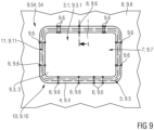
- Fig. 9 shows a schematic and explaining view of a window assembly 10 or 9.10 of Fig. 1 or Fig. 8 seen from outside which is installed in the body 8 or 9.8 of, for instance, a vehicle like a train.
- a number of reinforcing devices 6 and/or 9.6 or structural elements may be inserted with constant distance or step between each two neighboured reinforcing devices 6 and/or 9.6 as explained and shown in Fig. 9 on left and right sides of a perimeter or circumference of the window assembly 10 or 9.10.
- reinforcing devices 6 and/or 9.6 may also be arranged with variable distance or step as explained and shown in Fig. 9 on, for instance, a lower side of the window assembly 10 or 9.10.
- additional reinforcing devices 6 and/or 9.6 may be grouped in a specific zone of the perimeter of the window assembly or glazing on, for instance, an upper side of the window assembly 10 or 9.10.
Landscapes
- Engineering & Computer Science (AREA)
- Mechanical Engineering (AREA)
- Securing Of Glass Panes Or The Like (AREA)
Claims (14)
- Ensemble de fenêtre (10; 9.10) pour véhicule ou bâtiment, notamment pour train de voyageurs à grande vitesse, comprenant un vitrage (1; 9.1) composé d'une ou plusieurs vitres (2, 3; 9.2, 9.3) en verre, plastique et/ou céramique, une ouverture de fenêtre (7; 9.7) ménagée dans une construction (8; 9.8), un joint d'étanchéité (4; 9.4) en forme de cadre, disposé entre le vitrage (1; 9.1) et la construction (8; 9.8) et maintenant le vitrage (1; 9.1) sur la construction (8; 9.8) à l'intérieur de l'ouverture de fenêtre (7; 9.7), et un dispositif de renforcement (6; 9.6) pour renforcer le joint (4, 9.4), caractérisé en ce
que le dispositif de renforcement (6; 9.6) comprend un support (29; 9.29) et au moins un insert (6.1; 9.6.1) ou plusieurs inserts (6.1; 9.6.1), et une bande d'égalisation (6.2; 9.6.2) et que le joint (4; 9.4) comprend une partie intermédiaire (25; 9.25) disposée entre le support (29; 9.25) et la bande d'égalisation (6.2; 9.6.2), le ou les inserts (6.1; 9.6.1) reliant le support (29; 9.29) à la bande d'égalisation (6.2; 9.6.2). - Ensemble de fenêtre (10; 9.10) selon la revendication 1, caractérisé en ce que:le vitrage (1; 9.11) comprend une face (11; 9.11) du bord du vitrage ou un bord;la construction (8; 9.8) comprend une face (5; 9.5) du bord d'ouverture définissant l'ouverture (7; 9.7) de la fenêtre ménagée dans la construction (8; 9.8); etle joint (4; 9.4) maintient le vitrage (1; 9.1) sur la construction (8; 9.8) en recevant la face (5; 9.5) du bord d'ouverture ou le bord de la construction (8; 8.9) et la face (11; 9.11) du bord du vitrage ou le bord du vitrage (1; 9.1).
- Ensemble de fenêtre (10; 9.10) selon la revendication 1 ou 2, caractérisé en ce que le dispositif de renforcement (6; 9.6) comprend au moins un insert (6.1; 9.6.1) disposé le long du périmètre ou de la circonférence du joint (4; 9.4) pour renforcer le joint (4, 9.4).
- Ensemble de fenêtre (10; 9.10) selon l'une des revendications précédentes, caractérisé en ce que le dispositif de renforcement est fixe (9.6) ou au moins partiellement mobile (6) lors de l'installation ou du montage du vitrage (1; 9.1) sur la construction (8; 9.8) ou la carrosserie.
- Ensemble de fenêtre (10; 9.10) selon l'une des revendications précédentes, caractérisé en ce que la face (5; 9.5) du bord de la construction (8; 8.9) est profilé et comporte un évidement circonférentiel (9; 9.9) entre les parois parallèles (51; 9.51) et (52; 9.52) du bord profilé de la construction (8; 9.8); et
que le dispositif de renforcement (6; 9.6) comprend au moins un ou plusieurs éléments de renforcement (6.3; 9.6.3) s'étendant dans l'évidement (9; 9.9) entre les parois parallèles intérieure et extérieure (51; 9.51) et (52; 9.52) du bord profilé de la construction (8; 9.8). - Ensemble de fenêtre (10; 9.10) selon l'une des revendications précédentes, caractérisé en ce que le support (29; 9.29) est disposé ou collé sur une face périphérique extérieure (11; 9.11) du bord du vitrage ou sur un bord du vitrage (1; 9.1).
- Ensemble de fenêtre (10; 9.10) selon l'une des revendications précédentes, caractérisé en ce que le support (29) présente une partie de recouvrement (29.1; 9.29.1) recouvrant la face périphérique extérieure (11; 9.11) du vitrage, une partie intérieure (29.2; 9.29.2) s'étendant sur la surface intérieure (2.1; 9.2.1) du vitrage (1; 9.1), et une partie extérieure (29.3; 9.29.3) s'étendant sur une surface extérieure (3.1; 9.3.1) du vitrage (1; 9.1), les parties intérieure et extérieure (29.2; 9.29.2) et (29.3; 9.29.3) sont sensiblement perpendiculaires à la partie de recouvrement (29.1; 9.29.1) du support (29; 9.29) et parallèles à la surface intérieure et la surface extérieure (2.1, 3.1; 9.2.1, 9.3.1), la partie de recouvrement (29.1; 9.29.1) s'étendant entre les parties intérieure et extérieure (29.2; 9.29.2) et (29.3; 9.29.3) du joint (4; 4.9).
- Ensemble de fenêtre (10) selon l'une des revendications précédentes, caractérisé en ce que le support (29) comprend plusieurs trous traversants de fixation (29.4) ou alésages de fixation définis par des douilles ou manchons correspondants (29.5) s'étendant depuis un espace de verre (26) entre des vitres parallèles (2, 3) à travers les trous traversants de fixation (29.4) au-delà de la face (11) du bord du vitrage ou du bord du vitrage (1) jusque dans le joint (4).
- Ensemble de fenêtre (10) selon l'une des revendications précédentes, caractérisé en ce que la partie de recouvrement (29.1) du support (29) est disposée dans des évidements d'égalisation correspondants (11.1 et 11.2) prévus sur la face (11) du bord du vitrage ou le bord des vitres intérieure et extérieure (2 et 3) du vitrage (1) pour égaliser une épaisseur de la partie de recouvrement (29.1) du support (29) de telle sorte que la partie de recouvrement (29.1) affleure la face (11; 9.11) du bord du vitrage ou le bord du vitrage.
- Ensemble de fenêtre (10; 9.10) selon l'une des revendications précédentes, caractérisé en ce qu'au moins un élément de renforcement (6.3; 9.6.3) du dispositif de renforcement (6; 9.6) comprend une barre extérieure (6.31; 9.6.31) et une barre intérieure (6.32; 9.6.32) parallèles entre elles, et une partie intermédiaire (6.33; 9.6.33) reliant les barres extérieure et intérieure (6.31, 6.32; 9.6.31, 9.6.32), le ou les éléments de renforcement (6.3; 9.6.3) s'étendant dans un évidement (9; 9.9) de la construction (8; 9.8).
- Ensemble de fenêtre (10) selon l'une des revendications précédentes, caractérisé en ce qu'au moins un élément de renforcement (6.3) du dispositif de renforcement (6) est mobile ou pivotant d'une position de montage à une position verrouillée.
- Ensemble de fenêtre (10; 9.10) selon l'une des revendications précédentes, caractérisé en ce qu'une partie de paroi intérieure (24; 9.24) et/ou une partie de paroi extérieure (23; 9.23) du joint fait partie intégrante du joint (4; 9.4); ou en ce que la partie de paroi intérieure et/ou la partie de paroi extérieure du joint comportent une partie séparée fixée au joint après le montage du vitrage; ou la paroi intérieure (24) et/ou la paroi extérieure du joint comprennent au moins une partie mobile (24.1) reliée ou accouplée au joint (4) de manière articulée ou pliable; lors du montage du vitrage (1), la partie mobile (24.1) est en position ouverte pour permettre l'accès à un ou plusieurs éléments de renforcement mobiles (6.3) du dispositif de renforcement (6) afin de les déplacer de la position de montage à la position verrouillée ; et après le déplacement du ou des éléments de renforcement (6.3), la partie mobile (24.1) est poussée en position fermée, ce qui permet d'accéder à l'élément de renforcement mobile (6.3) et de mettre la partie mobile (24.1) du joint (4) en contact avec la surface (53; 54) de la construction.
- Ensemble de fenêtre (10; 9.10) selon l'une des revendications précédentes, caractérisé en ce que le dispositif de renforcement (6; 9.6) comprend un support (29; 9.29), au moins un insert (6.1; 9.6.1) ou plusieurs inserts (6.1; 9.6.1), une bande d'égalisation (6.2; 9.6.2) et au moins un élément de renforcement (6.3; 9.6.3) ou plusieurs éléments de renforcement (6.3; 9.6.3) montés sur la bande d'égalisation (6.2; 9.6.2) et s'étendant dans un évidement (9; 9.9) de la construction entre des parois intérieure et extérieure parallèles (51, 52) de la face profile du bord d'ouverture (11; 9.11) de la construction (8; 9.8).
- Ensemble de fenêtre (10; 9.10) selon la revendication 13, caractérisé en ce que le joint (4; 9.4) comprend une paroi intérieure (24; 9.24) ou âme intérieure, une paroi extérieure (23; 9.23) ou âme extérieure, et une partie intermédiaire (25; 9.25) s'étendant entre les parois extérieure et intérieure (23, 24), la paroi intérieure (24; 9.24) s'étend sur une surface intérieure (2.1; 9.2.1) du vitrage (1; 9.1) et sur une surface intérieure (53; 9.53) de la construction (8; 9.8), et la paroi extérieure (23 ; 9.23) s'étend sur une surface extérieure (3.1; 9.3.1) du vitrage (1; 9.1) et sur une surface extérieure (54; 9.54) de la construction (8; 9.8), et la partie intermédiaire du joint (25; 9.25) s'étend entre le support (29; 9.29) et la bande d'égalisation (6.2; 9.6.2) du dispositif de renforcement (6; 9.6).
Priority Applications (4)
| Application Number | Priority Date | Filing Date | Title |
|---|---|---|---|
| PL22425005.0T PL4227124T3 (pl) | 2022-02-10 | 2022-02-10 | Zespół okienny |
| EP22425005.0A EP4227124B1 (fr) | 2022-02-10 | 2022-02-10 | Ensemble fenêtre |
| ES22425005T ES3053070T3 (en) | 2022-02-10 | 2022-02-10 | Window assembly |
| PCT/EP2023/025056 WO2023151867A1 (fr) | 2022-02-10 | 2023-02-07 | Ensemble fenêtre |
Applications Claiming Priority (1)
| Application Number | Priority Date | Filing Date | Title |
|---|---|---|---|
| EP22425005.0A EP4227124B1 (fr) | 2022-02-10 | 2022-02-10 | Ensemble fenêtre |
Publications (3)
| Publication Number | Publication Date |
|---|---|
| EP4227124A1 EP4227124A1 (fr) | 2023-08-16 |
| EP4227124C0 EP4227124C0 (fr) | 2025-06-25 |
| EP4227124B1 true EP4227124B1 (fr) | 2025-06-25 |
Family
ID=81325145
Family Applications (1)
| Application Number | Title | Priority Date | Filing Date |
|---|---|---|---|
| EP22425005.0A Active EP4227124B1 (fr) | 2022-02-10 | 2022-02-10 | Ensemble fenêtre |
Country Status (4)
| Country | Link |
|---|---|
| EP (1) | EP4227124B1 (fr) |
| ES (1) | ES3053070T3 (fr) |
| PL (1) | PL4227124T3 (fr) |
| WO (1) | WO2023151867A1 (fr) |
Family Cites Families (3)
| Publication number | Priority date | Publication date | Assignee | Title |
|---|---|---|---|---|
| US2575854A (en) * | 1946-10-21 | 1951-11-20 | Adlake Co | Sash |
| DE2820620C3 (de) * | 1978-05-11 | 1980-11-06 | Ford-Werke Ag, 5000 Koeln | Elastische Dicht- und Befestigungsleiste zum Einfassen einer Scheibe, insbesondere einer Scheibe in einer Kraftfahrzeugkarosserie |
| US4591203A (en) * | 1984-04-02 | 1986-05-27 | General Motors Corporation | Modular window assembly |
-
2022
- 2022-02-10 ES ES22425005T patent/ES3053070T3/es active Active
- 2022-02-10 EP EP22425005.0A patent/EP4227124B1/fr active Active
- 2022-02-10 PL PL22425005.0T patent/PL4227124T3/pl unknown
-
2023
- 2023-02-07 WO PCT/EP2023/025056 patent/WO2023151867A1/fr not_active Ceased
Also Published As
| Publication number | Publication date |
|---|---|
| PL4227124T3 (pl) | 2025-11-03 |
| EP4227124C0 (fr) | 2025-06-25 |
| ES3053070T3 (en) | 2026-01-19 |
| EP4227124A1 (fr) | 2023-08-16 |
| WO2023151867A1 (fr) | 2023-08-17 |
Similar Documents
| Publication | Publication Date | Title |
|---|---|---|
| CN1976824B (zh) | 结构性门模组 | |
| US8695923B2 (en) | Window replacement for filling a window frame | |
| US20060175866A1 (en) | Motor vehicle egress window | |
| CN102770263B (zh) | 在航空器部件之间形成密封接合的方法 | |
| WO1993023287A1 (fr) | Porte coulissante exterieure pour avions | |
| JP2006036191A (ja) | 自動車バック・ドア | |
| US20120298799A1 (en) | Self-supporting cabin structural segment | |
| PT730540E (pt) | Automotora ligada a carris | |
| US7380865B2 (en) | Vehicle door and method for the production thereof | |
| CN1137302A (zh) | 用于建筑物的玻璃窗系统 | |
| JPS59140121A (ja) | 車両の窓 | |
| EP4227124A1 (fr) | Ensemble fenêtre | |
| US7188399B2 (en) | Method of fitting flush glazing | |
| GB2257190A (en) | Vehicle panel assembly, preferably for glazing | |
| EP4227123B1 (fr) | Ensemble fenêtre | |
| CN119142379B (zh) | 侧墙结构及车体、轨道车辆 | |
| US4777772A (en) | Externally insulated window mounting | |
| CN211943301U (zh) | 一种轻量化车门及墙板遮盖结构 | |
| US20030066255A1 (en) | Window assembly with glazing edge protection | |
| US8052203B2 (en) | Side panel for a vehicle | |
| KR102591848B1 (ko) | 철도차량용 측창문 | |
| US20070130851A1 (en) | Window assembly with serviceable glazing retention system | |
| CN116985606B (zh) | 一种碳纤维安全门结构及成型方法 | |
| CN214365805U (zh) | 内藏式骨架结构厢体卷帘门固定型材 | |
| SK121195A3 (en) | Multi-glazing filling and its application |
Legal Events
| Date | Code | Title | Description |
|---|---|---|---|
| PUAI | Public reference made under article 153(3) epc to a published international application that has entered the european phase |
Free format text: ORIGINAL CODE: 0009012 |
|
| STAA | Information on the status of an ep patent application or granted ep patent |
Free format text: STATUS: THE APPLICATION HAS BEEN PUBLISHED |
|
| AK | Designated contracting states |
Kind code of ref document: A1 Designated state(s): AL AT BE BG CH CY CZ DE DK EE ES FI FR GB GR HR HU IE IS IT LI LT LU LV MC MK MT NL NO PL PT RO RS SE SI SK SM TR |
|
| STAA | Information on the status of an ep patent application or granted ep patent |
Free format text: STATUS: REQUEST FOR EXAMINATION WAS MADE |
|
| 17P | Request for examination filed |
Effective date: 20231109 |
|
| RBV | Designated contracting states (corrected) |
Designated state(s): AL AT BE BG CH CY CZ DE DK EE ES FI FR GB GR HR HU IE IS IT LI LT LU LV MC MK MT NL NO PL PT RO RS SE SI SK SM TR |
|
| GRAP | Despatch of communication of intention to grant a patent |
Free format text: ORIGINAL CODE: EPIDOSNIGR1 |
|
| STAA | Information on the status of an ep patent application or granted ep patent |
Free format text: STATUS: GRANT OF PATENT IS INTENDED |
|
| INTG | Intention to grant announced |
Effective date: 20250328 |
|
| GRAS | Grant fee paid |
Free format text: ORIGINAL CODE: EPIDOSNIGR3 |
|
| GRAA | (expected) grant |
Free format text: ORIGINAL CODE: 0009210 |
|
| STAA | Information on the status of an ep patent application or granted ep patent |
Free format text: STATUS: THE PATENT HAS BEEN GRANTED |
|
| AK | Designated contracting states |
Kind code of ref document: B1 Designated state(s): AL AT BE BG CH CY CZ DE DK EE ES FI FR GB GR HR HU IE IS IT LI LT LU LV MC MK MT NL NO PL PT RO RS SE SI SK SM TR |
|
| REG | Reference to a national code |
Ref country code: GB Ref legal event code: FG4D |
|
| REG | Reference to a national code |
Ref country code: CH Ref legal event code: EP |
|
| REG | Reference to a national code |
Ref country code: DE Ref legal event code: R096 Ref document number: 602022016407 Country of ref document: DE |
|
| REG | Reference to a national code |
Ref country code: CH Ref legal event code: EP |
|
| REG | Reference to a national code |
Ref country code: IE Ref legal event code: FG4D |
|
| U01 | Request for unitary effect filed |
Effective date: 20250725 |
|
| U07 | Unitary effect registered |
Designated state(s): AT BE BG DE DK EE FI FR IT LT LU LV MT NL PT RO SE SI Effective date: 20250806 |
|
| PG25 | Lapsed in a contracting state [announced via postgrant information from national office to epo] |
Ref country code: NO Free format text: LAPSE BECAUSE OF FAILURE TO SUBMIT A TRANSLATION OF THE DESCRIPTION OR TO PAY THE FEE WITHIN THE PRESCRIBED TIME-LIMIT Effective date: 20250925 Ref country code: GR Free format text: LAPSE BECAUSE OF FAILURE TO SUBMIT A TRANSLATION OF THE DESCRIPTION OR TO PAY THE FEE WITHIN THE PRESCRIBED TIME-LIMIT Effective date: 20250926 |
|
| PG25 | Lapsed in a contracting state [announced via postgrant information from national office to epo] |
Ref country code: HR Free format text: LAPSE BECAUSE OF FAILURE TO SUBMIT A TRANSLATION OF THE DESCRIPTION OR TO PAY THE FEE WITHIN THE PRESCRIBED TIME-LIMIT Effective date: 20250625 |
|
| PG25 | Lapsed in a contracting state [announced via postgrant information from national office to epo] |
Ref country code: RS Free format text: LAPSE BECAUSE OF FAILURE TO SUBMIT A TRANSLATION OF THE DESCRIPTION OR TO PAY THE FEE WITHIN THE PRESCRIBED TIME-LIMIT Effective date: 20250925 |
|
| PG25 | Lapsed in a contracting state [announced via postgrant information from national office to epo] |
Ref country code: IS Free format text: LAPSE BECAUSE OF FAILURE TO SUBMIT A TRANSLATION OF THE DESCRIPTION OR TO PAY THE FEE WITHIN THE PRESCRIBED TIME-LIMIT Effective date: 20251025 |
|
| PG25 | Lapsed in a contracting state [announced via postgrant information from national office to epo] |
Ref country code: SM Free format text: LAPSE BECAUSE OF FAILURE TO SUBMIT A TRANSLATION OF THE DESCRIPTION OR TO PAY THE FEE WITHIN THE PRESCRIBED TIME-LIMIT Effective date: 20250625 |
|
| REG | Reference to a national code |
Ref country code: ES Ref legal event code: FG2A Ref document number: 3053070 Country of ref document: ES Kind code of ref document: T3 Effective date: 20260119 |
|
| PG25 | Lapsed in a contracting state [announced via postgrant information from national office to epo] |
Ref country code: CZ Free format text: LAPSE BECAUSE OF FAILURE TO SUBMIT A TRANSLATION OF THE DESCRIPTION OR TO PAY THE FEE WITHIN THE PRESCRIBED TIME-LIMIT Effective date: 20250625 |
|
| PG25 | Lapsed in a contracting state [announced via postgrant information from national office to epo] |
Ref country code: SK Free format text: LAPSE BECAUSE OF FAILURE TO SUBMIT A TRANSLATION OF THE DESCRIPTION OR TO PAY THE FEE WITHIN THE PRESCRIBED TIME-LIMIT Effective date: 20250625 |
|
| U20 | Renewal fee for the european patent with unitary effect paid |
Year of fee payment: 5 Effective date: 20260220 |
|
| PGFP | Annual fee paid to national office [announced via postgrant information from national office to epo] |
Ref country code: GB Payment date: 20260324 Year of fee payment: 5 |
|
| PGFP | Annual fee paid to national office [announced via postgrant information from national office to epo] |
Ref country code: ES Payment date: 20260319 Year of fee payment: 5 |
|
| PGFP | Annual fee paid to national office [announced via postgrant information from national office to epo] |
Ref country code: PL Payment date: 20260225 Year of fee payment: 5 |
|
| PLBE | No opposition filed within time limit |
Free format text: ORIGINAL CODE: 0009261 |
|
| STAA | Information on the status of an ep patent application or granted ep patent |
Free format text: STATUS: NO OPPOSITION FILED WITHIN TIME LIMIT |
|
| REG | Reference to a national code |
Ref country code: CH Ref legal event code: L10 Free format text: ST27 STATUS EVENT CODE: U-0-0-L10-L00 (AS PROVIDED BY THE NATIONAL OFFICE) Effective date: 20260507 |