EP4227791A1 - Verfahren zur bereitstellung eines bildschirms unter verwendung einer flexiblen anzeige und elektronische vorrichtung zur unterstützung davon - Google Patents
Verfahren zur bereitstellung eines bildschirms unter verwendung einer flexiblen anzeige und elektronische vorrichtung zur unterstützung davon Download PDFInfo
- Publication number
- EP4227791A1 EP4227791A1 EP21880346.8A EP21880346A EP4227791A1 EP 4227791 A1 EP4227791 A1 EP 4227791A1 EP 21880346 A EP21880346 A EP 21880346A EP 4227791 A1 EP4227791 A1 EP 4227791A1
- Authority
- EP
- European Patent Office
- Prior art keywords
- electronic device
- area
- state
- display
- housing
- Prior art date
- Legal status (The legal status is an assumption and is not a legal conclusion. Google has not performed a legal analysis and makes no representation as to the accuracy of the status listed.)
- Pending
Links
Images





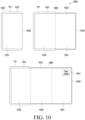

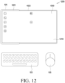
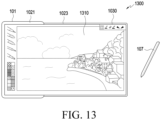


Classifications
-
- G—PHYSICS
- G06—COMPUTING OR CALCULATING; COUNTING
- G06F—ELECTRIC DIGITAL DATA PROCESSING
- G06F3/00—Input arrangements for transferring data to be processed into a form capable of being handled by the computer; Output arrangements for transferring data from processing unit to output unit, e.g. interface arrangements
- G06F3/14—Digital output to display device ; Cooperation and interconnection of the display device with other functional units
-
- H—ELECTRICITY
- H04—ELECTRIC COMMUNICATION TECHNIQUE
- H04M—TELEPHONIC COMMUNICATION
- H04M1/00—Substation equipment, e.g. for use by subscribers
- H04M1/72—Mobile telephones; Cordless telephones, i.e. devices for establishing wireless links to base stations without route selection
- H04M1/724—User interfaces specially adapted for cordless or mobile telephones
- H04M1/72448—User interfaces specially adapted for cordless or mobile telephones with means for adapting the functionality of the device according to specific conditions
- H04M1/72454—User interfaces specially adapted for cordless or mobile telephones with means for adapting the functionality of the device according to specific conditions according to context-related or environment-related conditions
-
- G—PHYSICS
- G06—COMPUTING OR CALCULATING; COUNTING
- G06F—ELECTRIC DIGITAL DATA PROCESSING
- G06F1/00—Details not covered by groups G06F3/00 - G06F13/00 and G06F21/00
- G06F1/16—Constructional details or arrangements
- G06F1/1613—Constructional details or arrangements for portable computers
- G06F1/1615—Constructional details or arrangements for portable computers with several enclosures having relative motions, each enclosure supporting at least one I/O or computing function
- G06F1/1616—Constructional details or arrangements for portable computers with several enclosures having relative motions, each enclosure supporting at least one I/O or computing function with folding flat displays, e.g. laptop computers or notebooks having a clamshell configuration, with body parts pivoting to an open position around an axis parallel to the plane they define in closed position
-
- G—PHYSICS
- G06—COMPUTING OR CALCULATING; COUNTING
- G06F—ELECTRIC DIGITAL DATA PROCESSING
- G06F1/00—Details not covered by groups G06F3/00 - G06F13/00 and G06F21/00
- G06F1/16—Constructional details or arrangements
- G06F1/1613—Constructional details or arrangements for portable computers
- G06F1/1615—Constructional details or arrangements for portable computers with several enclosures having relative motions, each enclosure supporting at least one I/O or computing function
- G06F1/1624—Constructional details or arrangements for portable computers with several enclosures having relative motions, each enclosure supporting at least one I/O or computing function with sliding enclosures, e.g. sliding keyboard or display
-
- G—PHYSICS
- G06—COMPUTING OR CALCULATING; COUNTING
- G06F—ELECTRIC DIGITAL DATA PROCESSING
- G06F1/00—Details not covered by groups G06F3/00 - G06F13/00 and G06F21/00
- G06F1/16—Constructional details or arrangements
- G06F1/1613—Constructional details or arrangements for portable computers
- G06F1/1633—Constructional details or arrangements of portable computers not specific to the type of enclosures covered by groups G06F1/1615 - G06F1/1626
- G06F1/1637—Details related to the display arrangement, including those related to the mounting of the display in the housing
- G06F1/1641—Details related to the display arrangement, including those related to the mounting of the display in the housing the display being formed by a plurality of foldable display components
-
- G—PHYSICS
- G06—COMPUTING OR CALCULATING; COUNTING
- G06F—ELECTRIC DIGITAL DATA PROCESSING
- G06F1/00—Details not covered by groups G06F3/00 - G06F13/00 and G06F21/00
- G06F1/16—Constructional details or arrangements
- G06F1/1613—Constructional details or arrangements for portable computers
- G06F1/1633—Constructional details or arrangements of portable computers not specific to the type of enclosures covered by groups G06F1/1615 - G06F1/1626
- G06F1/1637—Details related to the display arrangement, including those related to the mounting of the display in the housing
- G06F1/1652—Details related to the display arrangement, including those related to the mounting of the display in the housing the display being flexible, e.g. mimicking a sheet of paper, or rollable
-
- G—PHYSICS
- G06—COMPUTING OR CALCULATING; COUNTING
- G06F—ELECTRIC DIGITAL DATA PROCESSING
- G06F1/00—Details not covered by groups G06F3/00 - G06F13/00 and G06F21/00
- G06F1/16—Constructional details or arrangements
- G06F1/1613—Constructional details or arrangements for portable computers
- G06F1/1633—Constructional details or arrangements of portable computers not specific to the type of enclosures covered by groups G06F1/1615 - G06F1/1626
- G06F1/1675—Miscellaneous details related to the relative movement between the different enclosures or enclosure parts
- G06F1/1677—Miscellaneous details related to the relative movement between the different enclosures or enclosure parts for detecting open or closed state or particular intermediate positions assumed by movable parts of the enclosure, e.g. detection of display lid position with respect to main body in a laptop, detection of opening of the cover of battery compartment
-
- G—PHYSICS
- G06—COMPUTING OR CALCULATING; COUNTING
- G06F—ELECTRIC DIGITAL DATA PROCESSING
- G06F1/00—Details not covered by groups G06F3/00 - G06F13/00 and G06F21/00
- G06F1/16—Constructional details or arrangements
- G06F1/1613—Constructional details or arrangements for portable computers
- G06F1/1633—Constructional details or arrangements of portable computers not specific to the type of enclosures covered by groups G06F1/1615 - G06F1/1626
- G06F1/1675—Miscellaneous details related to the relative movement between the different enclosures or enclosure parts
- G06F1/1683—Miscellaneous details related to the relative movement between the different enclosures or enclosure parts for the transmission of signal or power between the different housings, e.g. details of wired or wireless communication, passage of cabling
-
- G—PHYSICS
- G06—COMPUTING OR CALCULATING; COUNTING
- G06F—ELECTRIC DIGITAL DATA PROCESSING
- G06F3/00—Input arrangements for transferring data to be processed into a form capable of being handled by the computer; Output arrangements for transferring data from processing unit to output unit, e.g. interface arrangements
- G06F3/01—Input arrangements or combined input and output arrangements for interaction between user and computer
- G06F3/048—Interaction techniques based on graphical user interfaces [GUI]
- G06F3/0481—Interaction techniques based on graphical user interfaces [GUI] based on specific properties of the displayed interaction object or a metaphor-based environment, e.g. interaction with desktop elements like windows or icons, or assisted by a cursor's changing behaviour or appearance
-
- G—PHYSICS
- G06—COMPUTING OR CALCULATING; COUNTING
- G06F—ELECTRIC DIGITAL DATA PROCESSING
- G06F3/00—Input arrangements for transferring data to be processed into a form capable of being handled by the computer; Output arrangements for transferring data from processing unit to output unit, e.g. interface arrangements
- G06F3/01—Input arrangements or combined input and output arrangements for interaction between user and computer
- G06F3/048—Interaction techniques based on graphical user interfaces [GUI]
- G06F3/0481—Interaction techniques based on graphical user interfaces [GUI] based on specific properties of the displayed interaction object or a metaphor-based environment, e.g. interaction with desktop elements like windows or icons, or assisted by a cursor's changing behaviour or appearance
- G06F3/04817—Interaction techniques based on graphical user interfaces [GUI] based on specific properties of the displayed interaction object or a metaphor-based environment, e.g. interaction with desktop elements like windows or icons, or assisted by a cursor's changing behaviour or appearance using icons
-
- G—PHYSICS
- G06—COMPUTING OR CALCULATING; COUNTING
- G06F—ELECTRIC DIGITAL DATA PROCESSING
- G06F3/00—Input arrangements for transferring data to be processed into a form capable of being handled by the computer; Output arrangements for transferring data from processing unit to output unit, e.g. interface arrangements
- G06F3/01—Input arrangements or combined input and output arrangements for interaction between user and computer
- G06F3/048—Interaction techniques based on graphical user interfaces [GUI]
- G06F3/0484—Interaction techniques based on graphical user interfaces [GUI] for the control of specific functions or operations, e.g. selecting or manipulating an object, an image or a displayed text element, setting a parameter value or selecting a range
-
- G—PHYSICS
- G06—COMPUTING OR CALCULATING; COUNTING
- G06F—ELECTRIC DIGITAL DATA PROCESSING
- G06F3/00—Input arrangements for transferring data to be processed into a form capable of being handled by the computer; Output arrangements for transferring data from processing unit to output unit, e.g. interface arrangements
- G06F3/14—Digital output to display device ; Cooperation and interconnection of the display device with other functional units
- G06F3/1423—Digital output to display device ; Cooperation and interconnection of the display device with other functional units controlling a plurality of local displays, e.g. CRT and flat panel display
-
- G—PHYSICS
- G09—EDUCATION; CRYPTOGRAPHY; DISPLAY; ADVERTISING; SEALS
- G09F—DISPLAYING; ADVERTISING; SIGNS; LABELS OR NAME-PLATES; SEALS
- G09F9/00—Indicating arrangements for variable information in which the information is built-up on a support by selection or combination of individual elements
- G09F9/30—Indicating arrangements for variable information in which the information is built-up on a support by selection or combination of individual elements in which the desired character or characters are formed by combining individual elements
- G09F9/301—Indicating arrangements for variable information in which the information is built-up on a support by selection or combination of individual elements in which the desired character or characters are formed by combining individual elements flexible foldable or roll-able electronic displays, e.g. thin LCD, OLED
-
- G—PHYSICS
- G09—EDUCATION; CRYPTOGRAPHY; DISPLAY; ADVERTISING; SEALS
- G09G—ARRANGEMENTS OR CIRCUITS FOR CONTROL OF INDICATING DEVICES USING STATIC MEANS TO PRESENT VARIABLE INFORMATION
- G09G3/00—Control arrangements or circuits, of interest only in connection with visual indicators other than cathode-ray tubes
- G09G3/03—Control arrangements or circuits, of interest only in connection with visual indicators other than cathode-ray tubes specially adapted for displays having non-planar surfaces, e.g. curved displays
- G09G3/035—Control arrangements or circuits, of interest only in connection with visual indicators other than cathode-ray tubes specially adapted for displays having non-planar surfaces, e.g. curved displays for flexible display surfaces
-
- H—ELECTRICITY
- H04—ELECTRIC COMMUNICATION TECHNIQUE
- H04M—TELEPHONIC COMMUNICATION
- H04M1/00—Substation equipment, e.g. for use by subscribers
- H04M1/02—Constructional features of telephone sets
- H04M1/0202—Portable telephone sets, e.g. cordless phones, mobile phones or bar type handsets
- H04M1/0206—Portable telephones comprising a plurality of mechanically joined movable body parts, e.g. hinged housings
- H04M1/0208—Portable telephones comprising a plurality of mechanically joined movable body parts, e.g. hinged housings characterized by the relative motions of the body parts
- H04M1/0214—Foldable telephones, i.e. with body parts pivoting to an open position around an axis parallel to the plane they define in closed position
- H04M1/0216—Foldable in one direction, i.e. using a one degree of freedom hinge
-
- H—ELECTRICITY
- H04—ELECTRIC COMMUNICATION TECHNIQUE
- H04M—TELEPHONIC COMMUNICATION
- H04M1/00—Substation equipment, e.g. for use by subscribers
- H04M1/02—Constructional features of telephone sets
- H04M1/0202—Portable telephone sets, e.g. cordless phones, mobile phones or bar type handsets
- H04M1/0206—Portable telephones comprising a plurality of mechanically joined movable body parts, e.g. hinged housings
- H04M1/0241—Portable telephones comprising a plurality of mechanically joined movable body parts, e.g. hinged housings using relative motion of the body parts to change the operational status of the telephone set, e.g. switching on/off, answering incoming call
- H04M1/0243—Portable telephones comprising a plurality of mechanically joined movable body parts, e.g. hinged housings using relative motion of the body parts to change the operational status of the telephone set, e.g. switching on/off, answering incoming call using the relative angle between housings
-
- H—ELECTRICITY
- H04—ELECTRIC COMMUNICATION TECHNIQUE
- H04M—TELEPHONIC COMMUNICATION
- H04M1/00—Substation equipment, e.g. for use by subscribers
- H04M1/02—Constructional features of telephone sets
- H04M1/0202—Portable telephone sets, e.g. cordless phones, mobile phones or bar type handsets
- H04M1/026—Details of the structure or mounting of specific components
- H04M1/0266—Details of the structure or mounting of specific components for a display module assembly
- H04M1/0268—Details of the structure or mounting of specific components for a display module assembly including a flexible display panel
-
- G—PHYSICS
- G06—COMPUTING OR CALCULATING; COUNTING
- G06F—ELECTRIC DIGITAL DATA PROCESSING
- G06F2203/00—Indexing scheme relating to G06F3/00 - G06F3/048
- G06F2203/048—Indexing scheme relating to G06F3/048
- G06F2203/04803—Split screen, i.e. subdividing the display area or the window area into separate subareas
-
- G—PHYSICS
- G09—EDUCATION; CRYPTOGRAPHY; DISPLAY; ADVERTISING; SEALS
- G09G—ARRANGEMENTS OR CIRCUITS FOR CONTROL OF INDICATING DEVICES USING STATIC MEANS TO PRESENT VARIABLE INFORMATION
- G09G2340/00—Aspects of display data processing
- G09G2340/04—Changes in size, position or resolution of an image
- G09G2340/0407—Resolution change, inclusive of the use of different resolutions for different screen areas
-
- G—PHYSICS
- G09—EDUCATION; CRYPTOGRAPHY; DISPLAY; ADVERTISING; SEALS
- G09G—ARRANGEMENTS OR CIRCUITS FOR CONTROL OF INDICATING DEVICES USING STATIC MEANS TO PRESENT VARIABLE INFORMATION
- G09G2340/00—Aspects of display data processing
- G09G2340/04—Changes in size, position or resolution of an image
- G09G2340/0464—Positioning
-
- G—PHYSICS
- G09—EDUCATION; CRYPTOGRAPHY; DISPLAY; ADVERTISING; SEALS
- G09G—ARRANGEMENTS OR CIRCUITS FOR CONTROL OF INDICATING DEVICES USING STATIC MEANS TO PRESENT VARIABLE INFORMATION
- G09G2354/00—Aspects of interface with display user
-
- G—PHYSICS
- G09—EDUCATION; CRYPTOGRAPHY; DISPLAY; ADVERTISING; SEALS
- G09G—ARRANGEMENTS OR CIRCUITS FOR CONTROL OF INDICATING DEVICES USING STATIC MEANS TO PRESENT VARIABLE INFORMATION
- G09G2356/00—Detection of the display position w.r.t. other display screens
-
- H—ELECTRICITY
- H04—ELECTRIC COMMUNICATION TECHNIQUE
- H04M—TELEPHONIC COMMUNICATION
- H04M1/00—Substation equipment, e.g. for use by subscribers
- H04M1/02—Constructional features of telephone sets
- H04M1/0202—Portable telephone sets, e.g. cordless phones, mobile phones or bar type handsets
- H04M1/0206—Portable telephones comprising a plurality of mechanically joined movable body parts, e.g. hinged housings
- H04M1/0208—Portable telephones comprising a plurality of mechanically joined movable body parts, e.g. hinged housings characterized by the relative motions of the body parts
- H04M1/0214—Foldable telephones, i.e. with body parts pivoting to an open position around an axis parallel to the plane they define in closed position
-
- H—ELECTRICITY
- H04—ELECTRIC COMMUNICATION TECHNIQUE
- H04M—TELEPHONIC COMMUNICATION
- H04M1/00—Substation equipment, e.g. for use by subscribers
- H04M1/02—Constructional features of telephone sets
- H04M1/0202—Portable telephone sets, e.g. cordless phones, mobile phones or bar type handsets
- H04M1/0206—Portable telephones comprising a plurality of mechanically joined movable body parts, e.g. hinged housings
- H04M1/0208—Portable telephones comprising a plurality of mechanically joined movable body parts, e.g. hinged housings characterized by the relative motions of the body parts
- H04M1/0235—Slidable or telescopic telephones, i.e. with a relative translation movement of the body parts; Telephones using a combination of translation and other relative motions of the body parts
-
- H—ELECTRICITY
- H04—ELECTRIC COMMUNICATION TECHNIQUE
- H04M—TELEPHONIC COMMUNICATION
- H04M1/00—Substation equipment, e.g. for use by subscribers
- H04M1/02—Constructional features of telephone sets
- H04M1/0202—Portable telephone sets, e.g. cordless phones, mobile phones or bar type handsets
- H04M1/0206—Portable telephones comprising a plurality of mechanically joined movable body parts, e.g. hinged housings
- H04M1/0241—Portable telephones comprising a plurality of mechanically joined movable body parts, e.g. hinged housings using relative motion of the body parts to change the operational status of the telephone set, e.g. switching on/off, answering incoming call
-
- H—ELECTRICITY
- H04—ELECTRIC COMMUNICATION TECHNIQUE
- H04M—TELEPHONIC COMMUNICATION
- H04M1/00—Substation equipment, e.g. for use by subscribers
- H04M1/72—Mobile telephones; Cordless telephones, i.e. devices for establishing wireless links to base stations without route selection
- H04M1/724—User interfaces specially adapted for cordless or mobile telephones
- H04M1/72403—User interfaces specially adapted for cordless or mobile telephones with means for local support of applications that increase the functionality
- H04M1/72409—User interfaces specially adapted for cordless or mobile telephones with means for local support of applications that increase the functionality by interfacing with external accessories
-
- H—ELECTRICITY
- H04—ELECTRIC COMMUNICATION TECHNIQUE
- H04M—TELEPHONIC COMMUNICATION
- H04M2201/00—Electronic components, circuits, software, systems or apparatus used in telephone systems
- H04M2201/38—Displays
-
- H—ELECTRICITY
- H04—ELECTRIC COMMUNICATION TECHNIQUE
- H04M—TELEPHONIC COMMUNICATION
- H04M2201/00—Electronic components, circuits, software, systems or apparatus used in telephone systems
- H04M2201/42—Graphical user interfaces
Definitions
- Various embodiments of the present invention relate to a method for providing a screen using a flexible display and an electronic device supporting the same.
- An electronic device including a flexible display may secure portability while providing a wide display.
- An electronic device with a multi-foldable display may provide a wider display than an electronic device including a foldable display in which the display may be folded only once.
- An electronic device including a flexible display provides a single wide display as the display extends, but does not properly provide a screen according to the extended state (e.g., folding state) of the display. Further, despite extension of the display, the electronic device with a flexible display provides a screen which does not consider the communication connection state with an external electronic device.
- Various embodiments of the present invention relate to a method for providing a screen using a flexible display based on the communication connection state with an external electronic device as the flexible display extends and an electronic device supporting the same.
- an electronic device may comprise a housing including a first housing, a second housing, and a third housing, a hinge unit comprising a first hinge unit configured to rotate the first housing and the second housing and a second hinge unit configured to rotate the second housing and the third housing, a display including a first area disposed on the first housing, a second area disposed on the second housing, and a third area disposed on the third housing, at least one sensor, a communication module, at least one processor operatively connected with the display, the at least one sensor, and the communication module, and a memory operatively connected with the processor.
- the memory may store instructions that, are configured to, when executed, enable the processor to detect a change of a state of the electronic device from a first state or a second state to a third state in which the second housing is unfolded about the hinge unit at a designated angle or more from the first housing and the third housing, through the at least one sensor, upon detecting the change of the state of the electronic device to the third state, identify whether there is an external electronic device communicatively connected or communicatively connectable to the electronic device through the communication module, when there is the external electronic device communicatively connected or communicatively connectable to the electronic device, identify a type of the external electronic device, and display a screen corresponding to a first mode or a screen corresponding to a second mode different from the first mode, through the first area, the second area, and the third area of the display, based on the type of the external electronic device.
- a method for providing a screen using a flexible display by an electronic device may comprise detecting a change of a state of the electronic device from a first state or a second state to a third state in which a second housing is unfolded about a hinge unit at a designated angle or more from a first housing and a third housing, through at least one sensor of the electronic device, upon detecting the change of the state of the electronic device to the third state, identifying whether there is an external electronic device communicatively connected or communicatively connectable to the electronic device through a communication module of the electronic device, when there is the external electronic device communicatively connected or communicatively connectable to the electronic device, identifying a type of the external electronic device, and displaying a screen corresponding to a first mode or a screen corresponding to a second mode different from the first mode, through a first area of the display, disposed on the first housing, a second area of the display, disposed on the second housing, and a third area of the
- an electronic device may comprise a housing, a display with an externally exposed area extendable according to movement through the housing, at least one sensor, a communication module, a processor operatively connected with the display, the at least one sensor, and the communication module, and a memory operatively connected with the processor.
- the memory may store instructions that, when executed, enable the processor to detect external exposure of an area of the display by a designated area or more through the at least one sensor, upon detecting the external exposure of the area of the display by the designated area or more, identify whether there is an external electronic device communicatively connected or communicatively connectable to the electronic device through the communication module, when there is the external electronic device communicatively connected or communicatively connectable to the electronic device, identify a type of the external electronic device, and display a screen corresponding to a first mode or a screen corresponding to a second mode different from the first mode through the display based on the type of the external electronic device.
- the method for providing a screen using a flexible display and the electronic device supporting the same may provide a screen based on the communication connection state with an external electronic device as the flexible display extends.
- FIG. 1 is a block diagram illustrating an electronic device 101 in a network environment 100 according to various embodiments.
- the electronic device 101 in the network environment 100 may communicate with an electronic device 102 via a first network 198 (e.g., a short-range wireless communication network), or an electronic device 104 or a server 108 via a second network 199 (e.g., a long-range wireless communication network).
- a first network 198 e.g., a short-range wireless communication network
- an electronic device 104 or a server 108 via a second network 199 (e.g., a long-range wireless communication network).
- the electronic device 101 may communicate with the electronic device 104 via the server 108.
- the electronic device 101 may include a processor 120, memory 130, an input module 150, a sound output module 155, a display module 160, an audio module 170, a sensor module 176, an interface 177, a connecting terminal 178, a haptic module 179, a camera module 180, a power management module 188, a battery 189, a communication module 190, a subscriber identification module (SIM) 196, or an antenna module 197.
- at least one (e.g., the connecting terminal 178) of the components may be omitted from the electronic device 101, or one or more other components may be added in the electronic device 101.
- some (e.g., the sensor module 176, the camera module 180, or the antenna module 197) of the components may be integrated into a single component (e.g., the display module 160).
- the processor 120 may execute, for example, software (e.g., a program 140) to control at least one other component (e.g., a hardware or software component) of the electronic device 101 coupled with the processor 120, and may perform various data processing or computation. According to one embodiment, as at least part of the data processing or computation, the processor 120 may store a command or data received from another component (e.g., the sensor module 176 or the communication module 190) in volatile memory 132, process the command or the data stored in the volatile memory 132, and store resulting data in non-volatile memory 134.
- software e.g., a program 140
- the processor 120 may store a command or data received from another component (e.g., the sensor module 176 or the communication module 190) in volatile memory 132, process the command or the data stored in the volatile memory 132, and store resulting data in non-volatile memory 134.
- the processor 120 may include a main processor 121 (e.g., a central processing unit (CPU) or an application processor (AP)), or an auxiliary processor 123 (e.g., a graphics processing unit (GPU), a neural processing unit (NPU), an image signal processor (ISP), a sensor hub processor, or a communication processor (CP)) that is operable independently from, or in conjunction with, the main processor 121.
- a main processor 121 e.g., a central processing unit (CPU) or an application processor (AP)
- auxiliary processor 123 e.g., a graphics processing unit (GPU), a neural processing unit (NPU), an image signal processor (ISP), a sensor hub processor, or a communication processor (CP)
- the main processor 121 may be configured to use lower power than the main processor 121 or to be specified for a designated function.
- the auxiliary processor 123 may be implemented as separate from, or as part of the main processor 121.
- the auxiliary processor 123 may control at least some of functions or states related to at least one component (e.g., the display module 160, the sensor module 176, or the communication module 190) among the components of the electronic device 101, instead of the main processor 121 while the main processor 121 is in an inactive (e.g., sleep) state, or together with the main processor 121 while the main processor 121 is in an active state (e.g., executing an application).
- the auxiliary processor 123 e.g., an image signal processor or a communication processor
- the auxiliary processor 123 may include a hardware structure specified for artificial intelligence model processing.
- the artificial intelligence model may be generated via machine learning. Such learning may be performed, e.g., by the electronic device 101 where the artificial intelligence is performed or via a separate server (e.g., the server 108). Learning algorithms may include, but are not limited to, e.g., supervised learning, unsupervised learning, semi-supervised learning, or reinforcement learning.
- the artificial intelligence model may include a plurality of artificial neural network layers.
- the artificial neural network may be a deep neural network (DNN), a convolutional neural network (CNN), a recurrent neural network (RNN), a restricted Boltzmann machine (RBM), a deep belief network (DBN), a bidirectional recurrent deep neural network (BRDNN), deep Q-network or a combination of two or more thereof but is not limited thereto.
- the artificial intelligence model may, additionally or alternatively, include a software structure other than the hardware structure.
- the memory 130 may store various data used by at least one component (e.g., the processor 120 or the sensor module 176) of the electronic device 101.
- the various data may include, for example, software (e.g., the program 140) and input data or output data for a command related thereto.
- the memory 130 may include the volatile memory 132 or the non-volatile memory 134.
- the program 140 may be stored in the memory 130 as software, and may include, for example, an operating system (OS) 142, middleware 144, or an application 146.
- OS operating system
- middleware middleware
- application application
- the input module 150 may receive a command or data to be used by other component (e.g., the processor 120) of the electronic device 101, from the outside (e.g., a user) of the electronic device 101.
- the input module 150 may include, for example, a microphone, a mouse, a keyboard, keys (e.g., buttons), or a digital pen (e.g., a stylus pen).
- the sound output module 155 may output sound signals to the outside of the electronic device 101.
- the sound output module 155 may include, for example, a speaker or a receiver.
- the speaker may be used for general purposes, such as playing multimedia or playing record.
- the receiver may be used for receiving incoming calls. According to an embodiment, the receiver may be implemented as separate from, or as part of the speaker.
- the display module 160 may visually provide information to the outside (e.g., a user) of the electronic device 101.
- the display 160 may include, for example, a display, a hologram device, or a projector and control circuitry to control a corresponding one of the display, hologram device, and projector.
- the display 160 may include a touch sensor configured to detect a touch, or a pressure sensor configured to measure the intensity of a force generated by the touch.
- the audio module 170 may convert a sound into an electrical signal and vice versa. According to an embodiment, the audio module 170 may obtain the sound via the input module 150, or output the sound via the sound output module 155 or a headphone of an external electronic device (e.g., an electronic device 102) directly (e.g., wiredly) or wirelessly coupled with the electronic device 101.
- an external electronic device e.g., an electronic device 102
- directly e.g., wiredly
- wirelessly e.g., wirelessly
- the sensor module 176 may detect an operational state (e.g., power or temperature) of the electronic device 101 or an environmental state (e.g., a state of a user) external to the electronic device 101, and then generate an electrical signal or data value corresponding to the detected state.
- the sensor module 176 may include, for example, a gesture sensor, a gyro sensor, an atmospheric pressure sensor, a magnetic sensor, an acceleration sensor, a grip sensor, a proximity sensor, a color sensor, an infrared (IR) sensor, a biometric sensor, a temperature sensor, a humidity sensor, or an illuminance sensor.
- the interface 177 may support one or more specified protocols to be used for the electronic device 101 to be coupled with the external electronic device (e.g., the electronic device 102) directly (e.g., wiredly) or wirelessly.
- the interface 177 may include, for example, a high definition multimedia interface (HDMI), a universal serial bus (USB) interface, a secure digital (SD) card interface, or an audio interface.
- HDMI high definition multimedia interface
- USB universal serial bus
- SD secure digital
- a connecting terminal 178 may include a connector via which the electronic device 101 may be physically connected with the external electronic device (e.g., the electronic device 102).
- the connecting terminal 178 may include, for example, a HDMI connector, a USB connector, a SD card connector, or an audio connector (e.g., a headphone connector).
- the haptic module 179 may convert an electrical signal into a mechanical stimulus (e.g., a vibration or motion) or electrical stimulus which may be recognized by a user via his tactile sensation or kinesthetic sensation.
- the haptic module 179 may include, for example, a motor, a piezoelectric element, or an electric stimulator.
- the camera module 180 may capture a still image or moving images.
- the camera module 180 may include one or more lenses, image sensors, image signal processors, or flashes.
- the power management module 188 may manage power supplied to the electronic device 101.
- the power management module 188 may be implemented as at least part of, for example, a power management integrated circuit (PMIC).
- PMIC power management integrated circuit
- the battery 189 may supply power to at least one component of the electronic device 101.
- the battery 189 may include, for example, a primary cell which is not rechargeable, a secondary cell which is rechargeable, or a fuel cell.
- the communication module 190 may support establishing a direct (e.g., wired) communication channel or a wireless communication channel between the electronic device 101 and the external electronic device (e.g., the electronic device 102, the electronic device 104, or the server 108) and performing communication via the established communication channel.
- the communication module 190 may include one or more communication processors that are operable independently from the processor 120 (e.g., the application processor (AP)) and supports a direct (e.g., wired) communication or a wireless communication.
- AP application processor
- the communication module 190 may include a wireless communication module 192 (e.g., a cellular communication module, a short-range wireless communication module, or a global navigation satellite system (GNSS) communication module) or a wired communication module 194 (e.g., a local area network (LAN) communication module or a power line communication (PLC) module).
- a wireless communication module 192 e.g., a cellular communication module, a short-range wireless communication module, or a global navigation satellite system (GNSS) communication module
- GNSS global navigation satellite system
- wired communication module 194 e.g., a local area network (LAN) communication module or a power line communication (PLC) module.
- LAN local area network
- PLC power line communication
- a corresponding one of these communication modules may communicate with the external electronic device 104 via a first network 198 (e.g., a short-range communication network, such as Bluetooth TM , wireless-fidelity (Wi-Fi) direct, or infrared data association (IrDA)) or a second network 199 (e.g., a long-range communication network, such as a legacy cellular network, a 5G network, a next-generation communication network, the Internet, or a computer network (e.g., local area network (LAN) or wide area network (WAN)).
- a first network 198 e.g., a short-range communication network, such as Bluetooth TM , wireless-fidelity (Wi-Fi) direct, or infrared data association (IrDA)
- a second network 199 e.g., a long-range communication network, such as a legacy cellular network, a 5G network, a next-generation communication network, the Internet, or a computer network (e.g., local area
- the wireless communication module 192 may identify or authenticate the electronic device 101 in a communication network, such as the first network 198 or the second network 199, using subscriber information (e.g., international mobile subscriber identity (IMSI)) stored in the subscriber identification module 196.
- subscriber information e.g., international mobile subscriber identity (IMSI)
- the wireless communication module 192 may support a 5G network, after a 4G network, and next-generation communication technology, e.g., new radio (NR) access technology.
- the NR access technology may support enhanced mobile broadband (eMBB), massive machine type communications (mMTC), or ultra-reliable and low-latency communications (URLLC).
- eMBB enhanced mobile broadband
- mMTC massive machine type communications
- URLLC ultra-reliable and low-latency communications
- the wireless communication module 192 may support a high-frequency band (e.g., the mmWave band) to achieve, e.g., a high data transmission rate.
- the wireless communication module 192 may support various technologies for securing performance on a high-frequency band, such as, e.g., beamforming, massive multiple-input and multiple-output (massive MIMO), full dimensional MIMO (FD-MIMO), array antenna, analog beam-forming, or large scale antenna.
- the wireless communication module 192 may support various requirements specified in the electronic device 101, an external electronic device (e.g., the electronic device 104), or a network system (e.g., the second network 199).
- the wireless communication module 192 may support a peak data rate (e.g., 20Gbps or more) for implementing eMBB, loss coverage (e.g., 164dB or less) for implementing mMTC, or U-plane latency (e.g., 0.5ms or less for each of downlink (DL) and uplink (UL), or a round trip of 1ms or less) for implementing URLLC.
- a peak data rate e.g., 20Gbps or more
- loss coverage e.g., 164dB or less
- U-plane latency e.g., 0.5ms or less for each of downlink (DL) and uplink (UL), or a round trip of 1ms or less
- the antenna module 197 may transmit or receive a signal or power to or from the outside (e.g., the external electronic device).
- the antenna module 197 may include one antenna including a radiator formed of a conductor or conductive pattern formed on a substrate (e.g., a printed circuit board (PCB)).
- the antenna module 197 may include a plurality of antennas (e.g., an antenna array). In this case, at least one antenna appropriate for a communication scheme used in a communication network, such as the first network 198 or the second network 199, may be selected from the plurality of antennas by, e.g., the communication module 190.
- the signal or the power may then be transmitted or received between the communication module 190 and the external electronic device via the selected at least one antenna.
- other parts e.g., radio frequency integrated circuit (RFIC)
- RFIC radio frequency integrated circuit
- the antenna module 197 may form a mmWave antenna module.
- the mmWave antenna module may include a printed circuit board, a RFIC disposed on a first surface (e.g., the bottom surface) of the printed circuit board, or adjacent to the first surface and capable of supporting a designated high-frequency band (e.g., the mmWave band), and a plurality of antennas (e.g., array antennas) disposed on a second surface (e.g., the top or a side surface) of the printed circuit board, or adjacent to the second surface and capable of transmitting or receiving signals of the designated high-frequency band.
- a RFIC disposed on a first surface (e.g., the bottom surface) of the printed circuit board, or adjacent to the first surface and capable of supporting a designated high-frequency band (e.g., the mmWave band)
- a plurality of antennas e.g., array antennas
- At least some of the above-described components may be coupled mutually and communicate signals (e.g., commands or data) therebetween via an inter-peripheral communication scheme (e.g., a bus, general purpose input and output (GPIO), serial peripheral interface (SPI), or mobile industry processor interface (MIPI)).
- an inter-peripheral communication scheme e.g., a bus, general purpose input and output (GPIO), serial peripheral interface (SPI), or mobile industry processor interface (MIPI)
- commands or data may be transmitted or received between the electronic device 101 and the external electronic device 104 via the server 108 coupled with the second network 199.
- the external electronic devices 102 or 104 each may be a device of the same or a different type from the electronic device 101.
- all or some of operations to be executed at the electronic device 101 may be executed at one or more of the external electronic devices 102, 104, or 108. For example, if the electronic device 101 should perform a function or a service automatically, or in response to a request from a user or another device, the electronic device 101, instead of, or in addition to, executing the function or the service, may request the one or more external electronic devices to perform at least part of the function or the service.
- the one or more external electronic devices receiving the request may perform the at least part of the function or the service requested, or an additional function or an additional service related to the request, and transfer an outcome of the performing to the electronic device 101.
- the electronic device 101 may provide the outcome, with or without further processing of the outcome, as at least part of a reply to the request.
- a cloud computing, distributed computing, mobile edge computing (MEC), or client-server computing technology may be used, for example.
- the electronic device 101 may provide ultra low-latency services using, e.g., distributed computing or mobile edge computing.
- the external electronic device 104 may include an Internet-of-things (IoT) device.
- the server 108 may be an intelligent server using machine learning and/or a neural network.
- the external electronic device 104 or the server 108 may be included in the second network 199.
- the electronic device 101 may be applied to intelligent services (e.g., smart home, smart city, smart car, or healthcare) based on 5G communication technology or IoT-related technology.
- the electronic device may be one of various types of electronic devices.
- the electronic devices may include, for example, a portable communication device (e.g., a smartphone), a computer device, a portable multimedia device, a portable medical device, a camera, a wearable device, or a home appliance.
- a portable communication device e.g., a smartphone
- a computer device e.g., a laptop, a desktop, a tablet, or a portable multimedia device
- a portable medical device e.g., a portable medical device
- camera e.g., a camera
- a wearable device e.g., a portable medical device
- each of such phrases as “A or B,” “at least one of A and B,” “at least one of A or B,” “A, B, or C,” “at least one of A, B, and C,” and “at least one of A, B, or C,” may include all possible combinations of the items enumerated together in a corresponding one of the phrases.
- such terms as “1st” and “2nd,” or “first” and “second” may be used to simply distinguish a corresponding component from another, and does not limit the components in other aspect (e.g., importance or order).
- an element e.g., a first element
- the element may be coupled with the other element directly (e.g., wiredly), wirelessly, or via a third element.
- module may include a unit implemented in hardware, software, or firmware, and may interchangeably be used with other terms, for example, “logic,” “logic block,” “part,” or “circuitry”.
- a module may be a single integral component, or a minimum unit or part thereof, adapted to perform one or more functions.
- the module may be implemented in a form of an application-specific integrated circuit (ASIC).
- ASIC application-specific integrated circuit
- Various embodiments as set forth herein may be implemented as software (e.g., the program 140) including one or more instructions that are stored in a storage medium (e.g., internal memory 136 or external memory 138) that is readable by a machine (e.g., the electronic device 101).
- a processor e.g., the processor 120
- the machine e.g., the electronic device 101
- the one or more instructions may include a code generated by a complier or a code executable by an interpreter.
- the machine-readable storage medium may be provided in the form of a non-transitory storage medium.
- non-transitory simply means that the storage medium is a tangible device, and does not include a signal (e.g., an electromagnetic wave), but this term does not differentiate between where data is semi-permanently stored in the storage medium and where the data is temporarily stored in the storage medium.
- a method may be included and provided in a computer program product.
- the computer program products may be traded as commodities between sellers and buyers.
- the computer program product may be distributed in the form of a machine-readable storage medium (e.g., compact disc read only memory (CD-ROM)), or be distributed (e.g., downloaded or uploaded) online via an application store (e.g., Play Store TM ), or between two user devices (e.g., smartphones) directly. If distributed online, at least part of the computer program product may be temporarily generated or at least temporarily stored in the machine-readable storage medium, such as memory of the manufacturer's server, a server of the application store, or a relay server.
- CD-ROM compact disc read only memory
- an application store e.g., Play Store TM
- two user devices e.g., smartphones
- each component e.g., a module or a program of the above-described components may include a single entity or multiple entities. Some of the plurality of entities may be separately disposed in different components. According to various embodiments, one or more of the above-described components may be omitted, or one or more other components may be added. Alternatively or additionally, a plurality of components (e.g., modules or programs) may be integrated into a single component. In such a case, according to various embodiments, the integrated component may still perform one or more functions of each of the plurality of components in the same or similar manner as they are performed by a corresponding one of the plurality of components before the integration.
- operations performed by the module, the program, or another component may be carried out sequentially, in parallel, repeatedly, or heuristically, or one or more of the operations may be executed in a different order or omitted, or one or more other operations may be added.
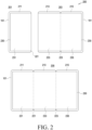
- FIG. 2 is a view 200 illustrating an electronic device 101 according to various embodiments.
- an electronic device 101 may include a first housing 211, a second housing 213, a third housing 215, a first hinge unit 221, a second hinge unit 223, and a display 230.
- the first housing 211, the second housing 213, and the third housing 215 may be denoted as housings, and the first hinge unit 221 and the second hinge unit 223 may be denoted as hinge units.
- the electronic device 101 may further include at least one of the components shown in FIG. 1 .
- first housing 211 and the second housing 213 may be connected to each other.
- one side surface of the first housing 211 and one side surface of the second housing 213 may be connected.
- the first housing 211 and the second housing 213 may be connected by the first hinge part 221.
- the first housing 211 and the second housing 213 may be connected rotatably or pivotably around (e.g., about) the first hinge unit 221.
- the first housing 211 and the second housing 213 may be rotated so that a first surface of the first housing 211 and a first surface of the second housing 213 change from facing in opposite directions to facing in the same direction or change from facing in the same direction to facing in opposite directions.
- the second housing 213 and the third housing 215 may be connected.
- one side surface of the second housing 213 and one side surface of the third housing 215 may be connected.
- the second housing 213 and the third housing 215 may be connected by the second hinge unit 223.
- the second housing 213 and the third housing 215 may be connected rotatably or pivotably around second hinge unit 223.
- the second housing 213 and the third housing 215 may be rotated so that a first surface of the second housing 213 and a first surface of the third housing 215 change from facing in opposite directions to facing in the same direction or change from facing in the same direction to facing in opposite directions.
- the display 230 may be visually exposed to the outside through the first housing 211, the second housing 213, and the third housing 215.
- the display 230 may be disposed in the first housing 211, the second housing 213, and the third housing 215 across the first hinge portion 221 and the second hinge portion 223.
- the display 230 may include a first area 231 disposed in the first housing 211, a second area 233 disposed in the second housing 213, and a third area 235 disposed in the third housing 215.
- the display 230 may be a foldable display.
- the display 230 may be folded in an out-folding manner in which the first area 231 and the second area 233 change from facing in the same direction to facing in opposite directions (e.g., the first area 231 and the second area 233 face away from each other, rather than facing each other).
- the display 230 may be folded an in-folding manner in which the second area 233 and the third area 235 change from facing in the same direction to facing each other.
- FIGS. 2 to 9 illustrate examples of folding or unfolding of the display 230
- the display 230 may be implemented to be bendable (or warpable), and examples in which the display 230 is implemented in a bendable form may be described in the same or similar manner to the examples in which the display 230 is folded or unfolded.
- 201 may indicate a state of the electronic device 101 in which the first area 231 of the display 230 faces in the direction opposite to the direction in which the second area 233 of the display 230 faces (e.g., the first area 231 and the second area 233 do not face each other but face in opposite directions), and the second area 233 and the third area 235 of the display 230 face each other.
- the state e.g., folding state or posture
- the first area 231 of the display 230 may be visually exposed to the outside, and the second area 233 and third area 235 of the display 230 may not be visually exposed to the outside.
- the first state of the electronic device 101 is not limited to the state of the electronic device indicated by 201.
- the first state of the electronic device 101 may include a state of the electronic device 101, in which the first area 231 of the display 230 faces in the same direction as the direction in which the second area 233 of the display 230 faces, and the second area 233 and third area 235 of the display 230 face each other.
- the first state of the electronic device 101 may include a state of the electronic device 101, in which the first housing 211 and the second housing 213 are unfolded about the first hinge unit 221, and the second housing 213 and the third housing 215 are fully folded about the second hinge unit 223.
- 203 may indicate a state of the electronic device 101, in which the first area 231 of the display 230 faces in the direction opposite to the direction in which the second area 233 of the display 230 faces, and the second area 233 and third area 235 of the display 230 face in the same direction.
- the state of the electronic device 101 indicated by 203 is denoted as a "second state of the electronic device 101" (or "second state").
- 205 may indicate a state of the electronic device 101 in which the first area 231, second area 233, and third area 235 of the display 230 face in the same direction.
- the state of the electronic device 101 as indicated by 205 is denoted as a "third state of the electronic device 101" (or "third state").
- the third state of the electronic device 101 is not limited to the state of the electronic device indicated by 205.
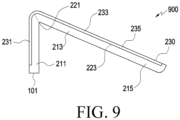
- the third state of the electronic device 101 may include a state in which the first housing 211 and the second housing 213 are at a designated first angle or more (or within a designated first angle range) about the first hinge unit 221, and the second housing 213 and the third housing 215 are unfolded at a designated second angle or more about the second hinge unit 223, as the state of the electronic device 101 of FIG. 9 described below.
- FIG. 3 is a block diagram 300 illustrating an electronic device 101 according to an embodiment.
- an electronic device 101 may include a communication module 310, a display 230, a sensor 330, a memory 340, and a processor 350. Although not shown in FIG. 3 , the electronic device 101 may further include a housing and a hinge unit as shown in FIG. 2 .
- the communication module 310 may communicatively connect the electronic device 101 and an external electronic device.
- the communication module may communicatively connect the electronic device 101 and the external electronic device wiredly or wirelessly.
- the communication module 310 may be at least partially the same as or similar to the communication module 190 of FIG. 1 and is thus not described below in detail.
- the display 230 is the same as the display 230 of FIG. 2 , and thus a detailed description of the display 230 is omitted.
- the sensor 330 may include a sensor (hereinafter, referred to as a "first sensor") for detecting the state (e.g., a folding state or posture) and folding angle of the electronic device 101.
- the first sensor may detect the first state, the second state, and the third state of the electronic device 101.
- the first sensor may detect the folding angle formed by the first housing 211 and the second housing 213 (e.g., the angle between the first housing 211 and the second housing 213 about the axis of the first hinge unit 221) and the folding angle formed by the second housing 213 and the third housing 215 (e.g., the angle between the second housing 213 and the third housing 215 about the axis of the second hinge unit 223).
- the first sensor may include at least one of a hall sensor, a proximity sensor, an angle sensor, a load cell, an infrared sensor, a pressure sensor, an acceleration sensor, a gyro sensor, or an electromagnetic sensor.
- the sensor for detecting the state and folding angle of the electronic device 101 is not limited to the above-described first sensor.
- the plurality of sensors may be disposed in the first housing 211, the second housing 213, and the third housing 215, respectively.
- the senor 330 may include a sensor (hereinafter, referred to as a "second sensor") for detecting reception of an electronic pen in the electronic device 101 or separation (e.g., detachment) of the electronic pen from the electronic device 101.
- the second sensor may include a sensor (e.g., a magnetic field sensor or coil sensor) capable of detecting a change in magnetic field induced by the coil (e.g., a charging coil) included in the electronic pen when the electronic pen is received (or attached) in or separated from the electronic device 101.
- the second sensor may include a sensor (e.g., hall sensor) capable of detecting whether the magnet included in the electronic pen is attached when the electronic pen is attached to the electronic device 101 or separated from the electronic device 101.
- the memory 340 may be included in the memory 130 of FIG. 1 .
- the memory 340 may store information for performing operations related to a method for providing a screen.
- the processor 350 may be included in the processor 120 of FIG. 1 .
- the processor 350 may perform operations related to a method for providing a screen using a flexible display (e.g., the display 230).
- an electronic device 101 may comprise a housing including a first housing 211, a second housing 213, and a third housing 215, a hinge unit comprising a first hinge unit 221 configured to rotate the first housing 211 and the second housing 213 and a second hinge unit 223 configured to rotate the second housing 213 and the third housing 215, a display 230 including a first area 231 disposed on the first housing 211, a second area 233 disposed on the second housing 213, and a third area 235 disposed on the third housing 215, at least one sensor 330, a communication module 310, at least one processor 350 operatively connected with the display 230, the at least one sensor 330, and the communication module 310, and a memory 340 operatively connected with the processor 350.
- a hinge unit comprising a first hinge unit 221 configured to rotate the first housing 211 and the second housing 213 and a second hinge unit 223 configured to rotate the second housing 213 and the third housing 215, a display 230 including a first area 231 disposed on
- the memory 340 may store instructions that, are configured to, when executed, enable the processor 350 to detect a change of a state of the electronic device 101 from a first state or a second state to a third state in which the second housing is unfolded about the hinge unit at a designated angle or more from the first housing and the third housing, through the at least one sensor 330, upon detecting the change of the state of the electronic device 101 to the third state, identify whether there is an external electronic device communicatively connected or communicatively connectable to the electronic device 101 through the communication module 310, when there is the external electronic device communicatively connected or communicatively connectable to the electronic device 101, identify a type of the external electronic device, and display a screen corresponding to a first mode or a screen corresponding to a second mode different from the first mode, through the first area 231, the second area 233, and the third area 235 of the display 230, based on the type of the external electronic device.
- the instructions may enable the processor 350 to, when the type of the external electronic device is an external input device, display the screen corresponding to the second mode through the first area 231, the second area 233, and the third area 235 of the display 230.
- the instructions may be configured to enable the processor 350 to, when the type of the external electronic device is the external input device, and an input for displaying the screen corresponding to the second mode is received, display the screen corresponding to the second mode, through the first area 231, the second area 233, and the third area 235 of the display 230.
- the instructions may be configured to enable the processor 350 to, when the external electronic device communicatively connected to the electronic device 101 is absent, or a designated external electronic device is not communicatively connected to the electronic device 101, display the screen corresponding to the first mode through the first area 231, the second area 233, and the third area 235 of the display 230.
- the instructions may be configured to enable the processor 350 to, upon detecting the change of the state of the electronic device 101 to the third state, identify the external electronic device communicatively connectable to the electronic device 101 through the communication module 310 and communicatively connect the external electronic device to the electronic device 101 through the communication module 310.
- the instructions may be configured to enable the processor 350 to detect a change of the state of the electronic device 101 to an unfolded state in which the first housing 211 and the second housing 213 are at a designated first angle or more about the first hinge unit, and the second housing 213 and the third housing 215 are unfolded about the second hinge unit at a designated second angle or more through the at least one sensor 330, upon detecting the change of the state of the electronic device 101 to the unfolded state, identify whether there is an external electronic device communicatively connected to the electronic device 101 through the communication module 310, when there is the external electronic device communicatively connected to the electronic device 101, identify a type of the external electronic device, and display the screen corresponding to the first mode or the screen corresponding to the second mode different from the first mode, through the second area 233 and the third area 235 of the display 230, based on the type of the external electronic device.
- the first state may be a state in which the first area 231 faces in a direction opposite to a direction in which the second area 233 aces, and the second area 233 and the third area 235 face each other
- the second state may be a state in which the first area 231 faces in the direction opposite to the direction in which the second area 233 faces, and the second area 233 and the third area 235 face in the same direction.
- the instructions may be configured to enable the processor 350 to display a plurality of first icons through the first area 231 in the first state, detect a change of the state of the electronic device 101 from the first state to the second state through the at least one sensor 330 and display a plurality of second icons at a second resolution higher than a first resolution of the plurality of first icons or display the plurality of second icons arranged by a distance longer than a distance between the plurality of first icons, through the second area 233 and the third area 235, in the second state.
- the screen corresponding to the first mode may include a plurality of third icons, different from the plurality of first icons and the plurality of second icons, and an icon corresponding to an application related to the external electronic device.
- the first mode may be a tablet mode
- the second mode may be a desktop mode
- FIG. 4 is a flowchart 400 illustrating a method for providing a screen using a flexible display according to various embodiments.
- the processor 350 may detect a change (or switch) of the state (e.g., folding state or posture) of the electronic device 101 from a first state or second state to a third state, through the sensor 330.
- a change or switch of the state (e.g., folding state or posture) of the electronic device 101 from a first state or second state to a third state, through the sensor 330.
- the processor 350 may detect a change of the state of the electronic device 101 from the first state to the second state and then a change from the second state to the third state, through the first sensor.
- the processor 350 may detect an immediate change of the state of the electronic device 101 from the first state to the third state through the first sensor. For example, the processor 350 may detect that the second housing 213 and the third housing 215 are unfolded about the second hinge unit 223 simultaneously with, or within a designated time from when, the first housing 211 and the second housing 213 are unfolded about the first hinge unit 221 from the first state of the electronic device 101 in which the first area 231 of the display 230 faces in the direction opposite to the direction in which the second area 233 of the display 230 faces, and the second area 233 and third area 235 of the display 230 face each other (or a state of the electronic device 101 in which the first area 231 of the display 230 faces in the same direction as the direction in which the second area 233 of the display 230 faces and the second area 233 and third area 235 of the display 230 face each other), through the first sensor.
- the processor 350 may change the screen configuration (or screen settings) displayed through the display 230.
- the processor 350 may display a first screen using the screen configuration corresponding to the first state of the electronic device 101 through the display 230 (e.g., the first area 231 of the display 230) (hereinafter, the screen displayed in the first state of the electronic device 101 is denoted as a "first screen").
- the processor 350 may display a second screen using the screen configuration corresponding to the second state of the electronic device 101 through the display 230 (e.g., the second area 233 and the third area 235 of the display 230) (hereinafter, the screen displayed in the second state of the electronic device 101 is denoted as a "second screen").
- the processor 350 may display the first screen including a plurality of first icons using a first screen configuration (e.g., arranged in a first array structure) through the display 230 (e.g., the first area 231).
- a first screen configuration e.g., arranged in a first array structure
- the processor 350 may display a plurality of second icons which result from a change in the display of the plurality of first icons, using a second screen configuration (e.g., arranged in a second array structure), through the display 230 (e.g., the second area 233 and the third area 235).
- the processor 350 may display the plurality of second icons having a second resolution (e.g., dots per inch (DPI) or pixel per inch (PPI)) higher than a first resolution of the plurality of first icons through the display 230 (e.g., the second area 233 and the third area 235).
- the processor 350 may display the plurality of second icons arranged in a longer distance than the distance between the plurality of first icons through the display 230 (e.g., the second area 233 and the third area 235).
- the first screen and the second screen are not limited to the above-described examples, and are described below in detail with reference to FIG. 5A .
- the processor 350 may detect that the state of the electronic device 101 changes (or switches) from an intermediate state (e.g., a state between the first state and the second state or a state between the second state and the third state) to the third state.
- an intermediate state e.g., a state between the first state and the second state or a state between the second state and the third state
- a change from the first state or second state to the third state may include a change from the intermediate state to the third state.
- the processor 350 may identify whether an external electronic device communicatively connected to the electronic device 101 is present (exists) through the communication module 310.
- the processor 350 may identify whether an external electronic device communicatively connected to the electronic device 101 is present through the communication module 310.
- the processor 350 may identify whether an external electronic device communicatively connected to the electronic device 101 is present through the short-range wireless communication module 310. In an embodiment, the processor 350 may identify whether an external electronic device communicatively connected to the electronic device 101 is present through the wired communication module 194.
- the processor 350 may identify the type of the external electronic device.
- the processor 350 may identify the type of the external electronic device communicatively connected to the electronic device 101, thereby identifying whether the external electronic device is a designated external electronic device. For example, the processor 350 may identify whether the external electronic device communicatively connected to the electronic device 101 is at least one of a keyboard, a mouse, a speaker, an earset, or an electronic pen. However, the operation of identifying whether the external electronic device communicatively connected to the electronic device 101 is a designated external electronic device may be omitted.
- the processor 350 may further perform the operation of identifying whether the electronic pen is detached (e.g., separated) from the electronic device 101 through the second sensor.
- the external electronic device communicatively connected to the electronic device 101 is not limited to the above-described examples.
- the processor 350 may display a screen corresponding to a first mode or a screen corresponding to a second mode, different from the first mode, through the display 230 (e.g., the first area 231, the second area 233, and the third area 235) based on the type of the external electronic device communicatively connected to the electronic device 101.
- the first mode may be a mode in which input to the electronic device 101 may be performed based on touch.
- the first mode may be a mode in which input to the electronic device 101 may be performed based on a touch to the display 230 with the user's finger (or electronic pen).
- an input to the electronic device 101 may be performed through the external input device (e.g., keyboard or mouse).
- the first mode may be a mode in which, when an application is executed, the execution screen of the application is displayed through the entire area of the display 230 (e.g., all of the first area 231, the second area 233, and the third area 235).
- the first mode may be referred to as a tablet mode.
- the second mode may be a mode in which input to the electronic device 101 may be performed through the external electronic device (e.g., external input device) communicatively connected to the electronic device 101.
- the second mode may be a mode in which input to the electronic device 101 may be performed through at least one of a keyboard or mouse communicatively connected to the electronic device 101.
- input to the electronic device 101 may be performed by touch as well as by the external electronic device.
- the second mode may be a mode for displaying a screen to provide personal computer (PC) environment (or PC experience).
- the second mode may be a mode for displaying the execution screen of an application using a window when the application is executed.
- the second mode may be denoted as a desktop mode or dex mode.
- the processor 350 may display a screen using the third screen configuration corresponding to the first mode, through the display 230 (e.g., the first area 231, the second area 233, and the third area 235) (hereinafter, the screen displayed in the first mode is denoted as a "third screen").
- the processor 350 may display the third screen through the display 230 (e.g., the first area 231, the second area 233, and the third area 235).
- the processor 350 may display a third screen including a plurality of third icons, different from the plurality of first icons included in the first screen and the plurality of second icons included in the second screen, through the display 230.
- the processor 350 may display the third screen through the display 230.
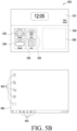
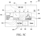
- the third screen displayed in the first mode may include the execution screen of the application displayed through the entire area (e.g., all of the first area 231, the second area 233, and the third area 235) of the display 230 when the application is executed. Examples of the third screen displayed in the first mode are described below in detail with reference to FIGS. 5B and 5C .
- the processor 350 may display a screen using a fourth screen configuration corresponding to the second mode through the display 230 (hereinafter, the screen displayed in the second mode is denoted as a "fourth screen").
- the fourth screen may be a screen to provide a PC environment.
- the fourth screen may include the execution screen of the application displayed using a window when the application is executed. Examples of the fourth screen displayed in the second mode are described below in detail with reference to FIG. 5B .
- the processor 350 may display the fourth screen corresponding to the second mode through the display 230 in response to reception of an additional input. For example, when the external electronic device communicatively connected to the electronic device 101 is a keyboard, the processor 350 may display the fourth screen corresponding to the second mode through the display 230 in response to reception of an input to a designated key from the keyboard, as the additional input.
- the processor 350 may display the fourth screen corresponding to the second mode through the display in response to reception of a designated input from the mouse (e.g., a single click, double click, or long click input through the mouse) as the additional input.
- the processor 350 may display a first object (e.g., icon) for displaying the third screen corresponding to the first mode and a second object for displaying the fourth screen corresponding to the second mode, through the display 230.
- the processor 350 may display the fourth screen corresponding to the second mode through the display 230 based on an input for selecting one of the second objects.
- the processor 350 may display an object for switching (e.g., toggling) between the third screen corresponding to the first mode and the fourth screen corresponding to the second mode through the display 230.
- the processor 350 may display the fourth screen corresponding to the second mode through the display 230 based on an input to the object.
- the fourth screen corresponding to the second mode is displayed in response to reception of an additional input, preventing display of the fourth screen corresponding to the second mode in a context where the user does not desire to display the fourth screen corresponding to the second mode.
- FIG. 5A is an example view 501 illustrating screens displayed in a first state and second state of an electronic device 101 according to various embodiments.
- the processor 350 may display a first screen 510 through the display 230 (e.g., the first area 231) in the first state of the electronic device 101.
- the processor 350 may display the first screen 510 including weather and time information 511 and a plurality of first icons 512, 513, 514, and 515 through the display 230 (e.g., the first area 231) in the first state of the electronic device 101.
- the processor 350 may display the second screen 520 through the display 230 (e.g., the second area 233 and the third area 235).
- the processor 350 may display the second screen 520 including weather and time information 521 and a plurality of second icons 522, 523, 524, and 525 through the display 230 (e.g., the second area 233 and the third area 235) in the second state of the electronic device 101.
- the processor 350 may change the screen configuration (or screen settings) displayed through the display 230.
- the processor 350 may display the plurality of second icons 522, 523, 524, and 525 with a second resolution higher than the first resolution of the plurality of first icons 512, 513, 514, and 515 included in the first screen 510 through the display 230 (e.g., the second area 233 and the third area 235).
- the processor 350 may display the plurality of second icons 522, 523, 524, and 525 arranged in a longer distance than the distance between the plurality of first icons 512, 513, 514, and 515 through the display 230 (e.g., the second area 233 and the third area 235).
- the processor 350 may identify whether an external electronic device communicatively connected to the electronic device 101 is present. When there is an external electronic device communicatively connected to the electronic device 101, the processor 350 may display an icon related to the external electronic device in some area 526 of the second screen 520.
- the processor 350 may display, in some area 526 (or denoted as an "additional area" of the second screen 520, an icon corresponding to (e.g., mapped to) an electronic pen-related application (e.g., a notepad application, a paint application, or an application for an air action feature capable of executing the function of the electronic device 101 based on information about the position (e.g., coordinates or motion) of the electronic pen).
- an electronic pen-related application e.g., a notepad application, a paint application, or an application for an air action feature capable of executing the function of the electronic device 101 based on information about the position (e.g., coordinates or motion) of the electronic pen).
- the processor 350 may display, in some area 526 or information 521 area of the second screen 520, an icon corresponding to an application for outputting audio signals through the earset or speaker (e.g., a video application, a video share application, or a music application).
- the processor 350 may display, in some area 526 of the second screen 520, an icon corresponding to an application capable of controlling the operation of the keyboard or mouse (e.g., an application for setting the keyboard or mouse).
- the processor 350 may display an application or application icon or widget related to the external electronic device communicatively connected to the electronic device 101 or whether to connect to the external electronic device, as a separate window, on the second screen 520.
- FIG. 5B is an example view 503 illustrating screens displayed in a third state of an electronic device 101 according to various embodiments.
- the processor 350 may display a third screen 530 corresponding to the first mode through the display 230 (e.g., the first area 231, the second area 233, and the third area 235), in the third state of the electronic device 101.
- the processor 350 may display the third screen 530 including weather and time information 531 and a plurality of third icons 532, 533, 534, and 535 through the display 230 (e.g., the first area 231, the second area 233, and the third area 235) in the third state of the electronic device 101.
- the processor 350 may display a plurality of third icons 532, 533, 534, and 535 including names related to the plurality of second icons 522, 523, 524, and 525 included in the second screen 520, through the display 230 (e.g., the first area 231, the second area 233, and the third area 235), as the third screen corresponding to the first mode.
- the processor 350 may display an icon related to the external electronic device in some area 536 of the third screen 530. According to various embodiments, the processor 350 may display an application or application icon or widget related to the external electronic device communicatively connected to the electronic device 101 or whether to connect to the external electronic device, as a separate window, on the third screen 530.
- the processor 350 may display a fourth screen 540 corresponding to the second mode through the display 230 (e.g., the first area 231, the second area 233, and the third area 235), in the third state of the electronic device 101.
- the processor 350 may display a fourth screen 540 (e.g., a background screen of the PC environment) including weather and time information, a plurality of fourth icons 542, and icons 543 displayed in the task bar, through the display 230.
- FIG. 5C is an example view 505 illustrating a screen corresponding to a first mode of an electronic device 101 according to various embodiments.
- the processor 350 may display the third screen 550 corresponding to the first mode through the display 230 in the third state of the electronic device 101.
- the processor 350 may display, through the display 230, the third screen 530 further including weather information 552 about the week of the date, in addition to the weather and time information 551 as compared with the second screen 520.
- the processor 350 may display, through the display 230, the third screen 530 including a plurality of third icons 553, 554, 555, and 556 having a different form from that of the plurality of second icons 522, 523, 524, and 525 included in the second screen 520.
- the processor 350 may display, through the display 230, an icon including detailed information about the application corresponding to the icon, as compared with the icon included in the first screen 510 or the second screen 520.
- the processor 350 may display an icon 553 including detailed information about the settings of the electronic device 101 through the display 230.
- the processor 350 may display an icon reflecting the use history through the display 230, as compared with the icon included in the first screen 510 or the second screen 520.
- the processor 350 may display, through the display 230, an icon 554 including information 554-1 indicating contacts (e.g., contacts to which the latest call was made or calls were frequently made during a designated period) based on the user's use history (e.g., call history) for the application.
- the processor 350 may display an icon reflecting the use history through the display 230, as compared with the icon included in the first screen 510 or the second screen 520.
- the processor 350 may display, through the display 230, icons corresponding to applications belonging to the same category or the same group, as compared with the icon included in the first screen 510 or the second screen 520.
- the processor 350 may display, through the display 230, an icon 555 including icons 555-1 corresponding to message applications (e.g., email message application or voice message application) belonging to the same category (e.g., message application category) as the text message application.
- message applications e.g., email message application or voice message application
- category e.g., message application category
- the processor 350 may display, through the display 230, an icon indicating the screen corresponding to the next depth (the next screen state when the application is executed on the screen), as compared with the icon included in the first screen 510 or the second screen 520.
- the processor 350 may display images 556-1 (e.g., thumbnail images) to be displayed after a gallery application is executed, through the display 230.
- the processor 350 may display, through the display 230, a third screen 550 including icons 557, 558, and 559 corresponding to applications (e.g., screen share application, video application, or game application) for outputting audio signals through the speaker or earset, which are not included in the second screen 520.
- applications e.g., screen share application, video application, or game application
- the processor 350 may display, through the display 230, a third screen 550 including icons normal state 1101 corresponding to applications (e.g., note application, paint application, or AR application) using the electronic pen, which are not included in the second screen 520.
- applications e.g., note application, paint application, or AR application
- FIG. 6 is an example view 600 illustrating a method for selecting a screen corresponding to a first mode or a screen corresponding to a second mode based on a user input in a third state of an electronic device 101 according to various embodiments.
- the processor 350 may identify an external electronic device communicatively connected to the electronic device 101 is present through the communication module 310.
- the processor 101 may display a first object for displaying the third screen corresponding to the first mode and a second object for displaying the fourth screen corresponding to the second mode, through the display 230.
- the processor 350 may display a window 611 including a first object 615 for displaying the third screen corresponding to the first mode and a second object 613 for displaying the fourth screen corresponding to the second mode, on the third screen 610 through the display 230.
- the processor 350 may display a fourth screen 620 corresponding to the second mode through the display 230 and display information 621 indicating that the electronic device 101 operates in the second mode, on the fourth screen 620.
- the processor 350 may control the display 230 to maintain display of the third screen 610 corresponding to the first mode.
- the method for selecting the screen corresponding to the first mode or the screen corresponding to the second mode based on the user's input in the third state of the electronic device 101 is not limited to the examples described in connection with FIG. 6 .
- the processor 350 may display the fourth screen corresponding to the second mode through the display 230 in response to reception of an input to a designated key from the keyboard.
- the processor 350 may display the fourth screen corresponding to the second mode through the display in response to reception of a designated input from the mouse (e.g., a single click, double click, or long click input through the mouse).
- the processor 350 may display an object for switching between the third screen corresponding to the first mode and the fourth screen corresponding to the second mode through the display 230.
- the processor 350 may display the fourth screen corresponding to the second mode through the display 230 based on an input to the object.
- FIG. 7 is a flowchart 700 illustrating a method for providing a screen using a flexible display according to various embodiments.
- the processor 350 may detect a change (or switch) of the state (e.g., folding state or posture) of the electronic device 101 from a first state or second state to a third state, through the sensor 330.
- a change or switch of the state (e.g., folding state or posture) of the electronic device 101 from a first state or second state to a third state, through the sensor 330.
- the processor 350 may identify an external electronic device communicatively connectable to the electronic device 101 is present through the communication module 310. For example, when the state of the electronic device 101 changes to the third state, the processor 350 may search for an external electronic device communicatively connectable to the electronic device 101 through the short-range wireless communication module.
- the processor 350 may perform communicative connection with the external electronic device through the communication module 310. For example, upon identifying an external electronic device communicatively connectable to the electronic device 101, the processor 350 may communicatively connect the external electronic device to the electronic device 101 through the communication module 310 based on a user input. As another example, upon identifying a plurality of external electronic devices communicatively connectable to the electronic device 101, the processor 350 may display information about the plurality of external electronic devices through the display 230. The processor 350 may select at least one external electronic device from among the plurality of external electronic devices based on a user input. The processor 350 may communicatively connect the selected at least one external electronic device to the electronic device 101 through the communication module 310.
- the processor 350 may communicatively connect the external electronic device to the electronic device 101 through the communication module, based on a running application. For example, when a video application is running, the processor 350 may communicatively connect to the earset or speaker related to the video application (e.g., capable of outputting audio signals as the video application is executed) through the communication module 310, automatically (e.g., in response to detection of a change of the state of the electronic device from the first state or second state to the third state).
- a running application e.g., the processor 350 may communicatively connect to the earset or speaker related to the video application (e.g., capable of outputting audio signals as the video application is executed) through the communication module 310, automatically (e.g., in response to detection of a change of the state of the electronic device from the first state or second state to the third state).
- the processor 350 may communicatively connect the mouse or electronic pen related to the paint application (e.g., capable of providing input to the function of the paint application) to the electronic device 101 through the communication module 310, automatically (e.g., in response to detection of a change of the state of the electronic device from the first state or second state to the third state).
- the processor 350 may communicatively connect the keyboard related to the message application (e.g., capable of providing input to the function of the message application) to the electronic device 101 through the communication module 310.
- the processor 350 may determine priorities between the plurality of external electronic devices. For example, upon identifying a plurality of external electronic devices communicatively connectable to the electronic device 101, the processor 350 may determine that the priority of the external electronic device (e.g., keyboard or mouse) capable of performing functions in the second mode in addition to the second mode is higher than the priorities of the other external electronic devices (e.g., earset, pen, and speaker). The processor 350 may communicatively connect the electronic device 101 with the external electronic devices in order of priority.
- the external electronic device e.g., keyboard or mouse
- the processor 350 may communicatively connect the electronic device 101 with the external electronic devices in order of priority.
- the processor 350 may communicatively connect with the latest external electronic device connected to the electronic device 101 or communicatively connect with the last connected electronic device 101 based on a user input through the communication module 310.
- the processor 350 may display the screen corresponding to the first mode or the screen corresponding to the second mode different from the first mode, through the display 230 (e.g., the first area 231, the second area 233, and the third area 235), based on the type of the external electronic device communicatively connected to the electronic device 101.
- FIG. 8 is a flowchart 800 illustrating a method for providing a screen using a flexible display in a designated state of an electronic device 101 according to various embodiments.
- FIG. 9 is an example view 900 illustrating a method for providing a screen using a flexible display in a designated state of an electronic device 101 according to various embodiments.
- the processor 350 may detect a change of the state (e.g., folding state or posture) of the electronic device 101 to a designated state through the sensor 330.
- a change of the state e.g., folding state or posture
- the designated state may be a state in which the angle between the first housing 211 and the second housing 213 about the first hinge unit 221 corresponds to a designated angle (or a designated angle range), and the second housing 213 and the third housing 215 are unfolded about the second hinge unit 223, as shown in FIG. 9 .
- the designated state may be a state in which the first housing 211 and the second housing 213 are at a designated first angle or more (or within a designated first angle range) about the first hinge unit 221, and the second housing 213 and the third housing 215 are unfolded at a designated second angle or more about the second hinge unit 223.
- the designated state of the electronic device 101 may also be denoted as a third state of the electronic device 101.
- the designated state may be a state in which as the first housing 211 supports the electronic device 101, and the second housing 213 and the third housing 215 are unfolded about the second hinge unit 223, the second area 233 and third area 235 of the display 230 form a predetermined angle from the ground.
- the processor 350 may detect a change of the state of the electronic device 101 from the first state or second state to the designated state through the first sensor.
- the designated state may be a state in which the electronic device 101 is mounted on an external device.
- the designated state may be a state in which the electronic device 101 is mounted on a charger (e.g., a charging station) capable of mounting the electronic device 101.
- the processor 350 may identify that the electronic device 101 is in the designated state.
- the designated state may be a state in which the electronic device 101 is mounted on an object (e.g., a book stand).
- the processor 350 may identify that the electronic device 101 is in the designated state.
- the processor 350 may identify whether an external electronic device communicatively connected to the electronic device 101 is present (exists) through the communication module 310.
- the processor 350 may identify the type of the external electronic device.
- the processor 350 may display a screen corresponding to a first mode or a screen corresponding to a second mode, different from the first mode, through the display 230 (e.g., the second area 233 and the third area 235) based on the type of the external electronic device communicatively connected to the electronic device 101.
- the processor 350 may display the third screen using the third screen configuration corresponding to the first mode, through the display 230.
- the processor 350 may display the third screen through the display 230.
- the processor 350 may display the third screen through the display 230.
- the processor 350 may display the fourth screen using a fourth screen configuration corresponding to the second mode through the display 230.
- the processor 350 may display the fourth screen corresponding to the second mode through the display 230 in response to reception of an additional input.
- a method for providing a screen using a flexible display by an electronic device 101 may comprise detecting a change of a state of the electronic device 101 from a first state or a second state to a third state in which a second housing 211 is unfolded about a hinge unit at a designated angle or more from a first housing 213 and a third housing 215, through at least one sensor 330 of the electronic device 101, upon detecting the change of the state of the electronic device 101 to the third state, identifying whether there is an external electronic device communicatively connected or communicatively connectable to the electronic device 101 through a communication module 310 of the electronic device 101, when there is the external electronic device communicatively connected or communicatively connectable to the electronic device 101, identifying a type of the external electronic device, and displaying a screen corresponding to a first mode or a screen corresponding to a second mode different from the first mode, through a first area 231 of the display 230, disposed on the first housing, a
- displaying the screen corresponding to the first mode or the screen corresponding to the second mode different from the first mode may include, when the type of the external electronic device is an external input device, displaying the screen corresponding to the second mode through the first area 231, the second area 233, and the third area 235 of the display 230.
- displaying the screen corresponding to the first mode or the screen corresponding to the second mode different from the first mode may include, when the type of the external electronic device is the external input device, and an input for displaying the screen corresponding to the second mode is received, displaying the screen corresponding to the second mode, through the first area 231, the second area 233, and the third area 235 of the display 230.
- displaying the screen corresponding to the first mode or the screen corresponding to the second mode different from the first mode may include, when the external electronic device communicatively connected to the electronic device 101 is absent, or a designated external electronic device is not communicatively connected to the electronic device 101, displaying the screen corresponding to the first mode through the first area 231, the second area 233, and the third area 235 of the display 230.
- the method may further comprise, upon detecting the change of the state of the electronic device 101 to the third state, identifying the external electronic device communicatively connectable to the electronic device 101 through the communication module 310 and communicatively connecting the external electronic device to the electronic device 101 through the communication module 310.
- the method may further comprise detecting a change of the state of the electronic device 101 to an unfolded state in which the first housing 211 and the second housing 213 are at a designated first angle or more about a first hinge unit 221, and the second housing 213 and the third housing 215 are unfolded about a second hinge unit at a designated second angle or more through the at least one sensor 330, upon detecting the change of the state of the electronic device 101 to the unfolded state, identifying whether there is an external electronic device communicatively connected to the electronic device 101 through the communication module 310, when there is the external electronic device communicatively connected to the electronic device 101, identifying a type of the external electronic device, and displaying the screen corresponding to the first mode or the screen corresponding to the second mode different from the first mode, through the second area 233 and the third area 235 of the display 230, based on the type of the external electronic device.
- the first state may be a state in which the first area 231 faces in a direction opposite to a direction in which the second area 233 aces, and the second area 233 and the third area 235 face each other
- the second state may be a state in which the first area 231 faces in the direction opposite to the direction in which the second area 233 faces, and the second area 233 and the third area 235 face in the same direction.
- the method may further comprise displaying a plurality of first icons through the first area 231 in the first state, detecting a change of the state of the electronic device 101 from the first state to the second state through the at least one sensor 330 and displaying a plurality of second icons at a second resolution higher than a first resolution of the plurality of first icons or displaying the plurality of second icons arranged by a distance than longer a distance between the plurality of first icons, through the second area 233 and the third area 235, in the second state.
- the screen corresponding to the first mode may include a plurality of third icons, different from the plurality of first icons and the plurality of second icons, and an icon corresponding to an application related to the external electronic device.
- the first mode may be a tablet mode
- the second mode may be a desktop mode
- FIG. 10 is a view 1000 illustrating an electronic device 101 according to various embodiments.
- the electronic device 101 may be an electronic device 101 including a display 1030 at least a portion of which is slidable.
- the electronic device 101 may include a first housing 1021, a second housing 1023, and a display 1030. In an embodiment, although not shown in FIG. 10 , the electronic device 101 may further include at least one of the components shown in FIG. 1 .
- the second housing 1023 may be disposed to be slidable on the first housing 1021.
- the second housing 1023 may be disposed to reciprocate by a predetermined distance with respect to the first housing 1021.
- the display 1030 may be a flexible display.
- a portion of a second area 1033 of the display 1030 may be transformed into a curved shape while the second housing 1023 slides on the first housing 1021.
- the display 1030 may be guided by a roller disposed in the first housing 1021 to extend while the second housing 1023 slides on (or in) the first housing 1021.
- the partial area of the display 1030 may be exposed to the outside as the second housing 1023 slides on (or in) the first housing 1021.
- 1001 may indicate the state of the electronic device 101 in which the first area 1031 of the display 1030 is visually exposed to the outside.
- 1001 may indicate the state of the electronic device 101 in which the second area 1033 of the display 1030 extending from the first area 1031 of the display 1030 and the third area 1035 of the display 1030 extending from the second area 1033 of the display 1030 are received (or inserted) in the first housing 1021, and the first area 1031 of the display 1030 is exposed to the outside.
- the state of the electronic device 101 indicated by 1001 is denoted as a "first state of the electronic device 101" (or "first state").
- 1003 may indicate the state of the electronic device 101 in which the first area 1031 and second area 1033 of the display 1030 are visually exposed to the outside.
- 1003 may indicate the state in which as the second housing 1023 slides on (or in) the first housing 1021, the second area 1033 of the display 1030, in addition to the first area 1031 of the display 1030, is exposed to the outside.
- the state of the electronic device 101 indicated by 1003 is denoted as a "second state of the electronic device 101" (or "second state").
- 1005 may indicate a state of the electronic device 101 in which the first area 1031, second area 1033, and third area 1035 of the display 1030 are visually exposed to the outside.
- 1005 may indicate the state in which as the second housing 1023 slides on (or in) the first housing 1021, the third area 1035 of the display 1030, in addition to the first area 1031 and second area 1033 of the display 1030, is exposed to the outside.
- the state of the electronic device 101 as indicated by 1005 is denoted as a "third state of the electronic device 101" (or "third state").
- an object 1041 for switching the screen corresponding to the first mode and the screen corresponding to the second mode may be displayed through the display 1030.
- the method for displaying the screen corresponding to the first mode and the screen corresponding to the second mode is not limited to the above-described example.
- the electronic device 101 may further include a sensor (e.g., the sensor 330) capable of detecting the first state, second state, and third state of the electronic device 101.
- the electronic device 101 may further include a sensor (e.g., hall sensor, mechanically operating switching element, or photo detector) (hereinafter, referred to as a "first sensor") capable of detecting an increase or decrease in the area of the display 1030 (or slide of the second housing 1023 on the first housing 1021).
- the electronic device 101 may further include at least one sensor capable of detecting the externally exposed area of the display 1030.
- a sensor for detecting reception (or attachment) of an electronic pen in the electronic device 101 or separation (e.g., detachment) of the electronic pen from the electronic device 101.
- FIG. 11 is a flowchart 1100 illustrating a method for providing a screen using a flexible display 1030 according to various embodiments.
- the processor 350 may detect that the area of the display 1030 is visually exposed to the outside by a designated area or more through the sensor (e.g., the sensor 330).
- the processor 350 may detect that the state of the electronic device 101 changes from the first state or second state to the third state through the first sensor (e.g., hall sensor, mechanically operating switching element, or photo detector). For example, the processor 350 may detect external exposure of the third area 1035, in addition to the first area 1031 and the second area 1033 of the display 1030, through the first sensor. In an embodiment, the processor 350 may detect a change of the state of the electronic device 101 from the first state or second state to a state in which a portion of the third area 1035 is exposed to the outside (e.g., a state in which a portion of the third area 1035 is exposed by a designated area or more), through the first sensor.
- the first sensor e.g., hall sensor, mechanically operating switching element, or photo detector.
- the processor 350 may detect external exposure of the third area 1035, in addition to the first area 1031 and the second area 1033 of the display 1030, through the first sensor.
- the processor 350 may detect a change of the state of the electronic device
- the processor 350 may identify whether an external electronic device communicatively connected to the electronic device 101 is present (exists) through the communication module 310.
- the processor 350 may identify whether there is an external electronic device communicatively connected to the electronic device 101 through the communication module 310.
- the processor 350 may identify whether an external electronic device communicatively connected to the electronic device 101 is present through the short-range wireless communication module. In an embodiment, the processor 350 may identify whether an external electronic device communicatively connected to the electronic device 101 is present through the wired communication module 194.
- the processor 350 may identify the type of the external electronic device.
- the processor 350 may identify the type of the external electronic device communicatively connected to the electronic device 101, thereby identifying whether the external electronic device is a designated external electronic device. For example, the processor 350 may identify whether the external electronic device communicatively connected to the electronic device 101 is at least one of a keyboard, a mouse, a speaker, an earset, or an electronic pen. However, the operation of identifying whether the external electronic device communicatively connected to the electronic device 101 is a designated external electronic device may be omitted.
- the processor 350 may identify whether the electronic pen is detached (e.g., separated) from the electronic device 101 through the second sensor.
- the external electronic device communicatively connected to the electronic device 101 is not limited to the above-described examples.
- the processor 350 may display a screen corresponding to a first mode or a screen corresponding to a second mode, different from the first mode, through the display 1030 (e.g., the first area 1031, the second area 1033, and the third area 1035) based on the type of the external electronic device communicatively connected to the electronic device 101.
- the processor 350 may perform the operation of, when the area of the display 1030 is exposed to the outside by a designated area or more, identifying an external electronic device communicatively connectable to the electronic device 101, the operation of performing communicative connection with the external electronic device, and the operation of displaying the screen corresponding to the first mode or the screen corresponding to the second mode based on the type of the external electronic device, as described in connection with the examples of FIG. 9 .
- FIG. 12 is an example view 1200 illustrating a screen corresponding to a second mode according to various embodiments.
- FIG. 13 is an example view 1300 illustrating a screen corresponding to a first mode according to various embodiments.
- the processor 350 may display the screen corresponding to the second mode through the display 1030.
- the processor 350 may display the screen 1210 (e.g., background screen) corresponding to the second mode through the first area 1031, second area 1033, and third area 1035 of the display 1030.
- the processor 350 may display the screen corresponding to the first mode through the display 1030. For example, as shown in FIG.
- the processor 350 may display a screen 1310 (e.g., execution screen of the paint application) corresponding to the first mode through the first area 1031, second area 1033, and third area 1035 of the display 1030.
- a screen 1310 e.g., execution screen of the paint application
- FIG. 14 is a view 1400 illustrating an electronic device 101 according to various embodiments.
- the electronic device 101 may be an electronic device 101 including a display 1430 at least a portion of which is slidable.
- the electronic device 101 may include a first housing 1421, a second housing 1423, and a display 1430. In an embodiment, although not shown in FIG. 14 , the electronic device 101 may further include at least one of the components shown in FIG. 1 .
- the second housing 1423 may be disposed to be slidable on the first housing 1421.
- the display 1430 may be a flexible display. For example, a portion of a second area 1433 of the display 1430 may be transformed into a curved shape while the second housing 1423 slides on (or in) the first housing 1421.
- the display 1430 may be guided by a roller disposed in the second housing 1423 to extend while the second housing 1423 slides on (or in) the first housing 1421.
- the partial area of the display 1430 may be exposed to the outside as the second housing 1423 slides on (or in) the first housing 1421.
- 1401 may indicate the state of the electronic device 101 in which the first area 1431 of the display 1430 is exposed to the outside.
- 1401 may indicate the state of the electronic device 101 in which the second area 1433 of the display 1430 extending from the first area 1431 of the display 1430 and the third area 1435 of the display 1430 extending from the second area 1433 of the display 1430 are received (or inserted) in the second housing 1423, and the first area 1431 of the display 1430 is exposed to the outside.
- the state of the electronic device 101 indicated by 1401 is denoted as a "first state of the electronic device 101" (or "first state").
- 1403 may indicate the state of the electronic device 101 in which the first area 1431 and second area 1433 of the display 1430 are exposed to the outside.
- 1403 may indicate the state in which as the second housing 1423 slides on (or in) the first housing 1421, the second area 1433 of the display 1430, in addition to the first area 1431 of the display 1430, is exposed to the outside.
- the state of the electronic device 101 indicated by 1403 is denoted as a "second state of the electronic device 101" (or "second state").
- 1405 may indicate a state of the electronic device 101 in which the first area 1431, second area 1433, and third area 1435 of the display 1430 are exposed to the outside.
- 1005 may indicate the state in which as the second housing 1423 slides on (or in) the first housing 1421, the third area 1435 of the display 1430, in addition to the first area 1431 and second area 1433 of the display 1430, is exposed to the outside.
- the state of the electronic device 101 as indicated by 1405 is denoted as a "third state of the electronic device 101" (or "third state").
- the electronic device 101 may further include a sensor (e.g., the sensor 330) capable of detecting the first state, second state, and third state of the electronic device 101.
- the electronic device 101 may further include a sensor (e.g., hall sensor, mechanically operating switching element, or photo detector) capable of detecting an increase or decrease in the area of the display 1430 (or slide of the second housing 1423 on the first housing 1421).
- the electronic device 101 may further include at least one sensor capable of detecting the externally exposed area of the display 1430.
- a sensor for detecting reception of an electronic pen in the electronic device 101 or separation (e.g., detachment) of the electronic pen from the electronic device 101.
- the examples of the operation of providing a screen by the electronic device 101 of FIG. 14 are at least partially identical or similar to the examples described in connection with FIGS. 10 to 13 , and thus, no detailed description thereof is given.
- FIG. 15 is a view 1500 illustrating an electronic device 101 according to various embodiments.
- the electronic device 101 may be an electronic device 101 at least a portion of the display 1530 of which is rollable.
- the electronic device 101 may include a housing 1521, a first member 1523, and a display 1530. In an embodiment, although not shown in FIG. 15 , the electronic device 101 may further include at least one of the components shown in FIG. 1 .
- the housing 1521 may allow the display 1530 to extend as the first member 1523 is moved by the user.
- the housing 1521 may include a roller to allow the display 1530 to extend as the first member 1523 moves.
- the display 1530 may be a rollable display 1530.
- at least a partial area of the display 1530 may be in a state of having transformed into a curved shape.
- the display 1530 may be guided by the roller disposed in the housing 1521 to extend while the first member 1523 moves from the housing 1521. For example, as the first member 1523 is moved from the housing 1521, the externally exposed area of the display 1530 may be increased.
- 1501 may indicate the state of the electronic device 101 in which the first area 1531 of the display 1530 is exposed to the outside.
- 1501 may indicate a state in which as the first member 1523 is moved with respect to the housing 1521, the first area 1531 of the display 1530 is exposed to the outside from the state in which the entire area of the display 1530 is received (or inserted) in the housing 1521.
- the state of the electronic device 101 indicated by 1501 is denoted as a "first state of the electronic device 101" (or "first state").
- 1503 may indicate the state of the electronic device 101 in which the first area 1531 and second area 1533 of the display 1530 are exposed to the outside.
- 1503 may indicate a state in which as the first member 1523 is moved with respect to the housing 1521, the second area 1533 of the display 1530, in addition to the first area 1531 of the display 1530, is exposed to the outside.
- the state of the electronic device 101 indicated by 1503 is denoted as a "second state of the electronic device 101" (or "second state").
- 1505 may indicate a state of the electronic device 101 in which the first area 1531, second area 1533, and third area 1535 of the display 1530 are exposed to the outside.
- 1005 may indicate a state in which as the first member 1523 is moved with respect to the housing 1521, the second area 1533 and third area 1535 of the display 1530, in addition to the first area 1531 of the display 1530, is exposed to the outside.
- the state of the electronic device 101 as indicated by 1405 is denoted as a "third state of the electronic device 101" (or "third state").
- the electronic device 101 may further include a sensor capable of detecting the first state, second state, and third state of the electronic device 101.
- the electronic device 101 may further include a sensor (e.g., the sensor 330) capable of detecting an increase or decrease in the externally exposed area of the display 1530.
- the electronic device 101 may further include at least one sensor capable of detecting the externally exposed area of the display 1530.
- the examples of the operation of providing a screen by the electronic device 101 of FIG. 15 are at least partially identical or similar to the examples described in connection with FIGS. 10 to 13 , and thus, no detailed description thereof is given.
- the electronic device 101 may further include other various states depending on the externally exposed area of the display without being limited to the first state, second state, and third state of the electronic device 101.
- the electronic device 101 may include more subdivided states according to an increase or decrease in the externally exposed area of the display.
- an electronic device 101 may comprise a housing 1021 and 1023, a display 1030 with an externally exposed area extendable according to movement through the housing 1021 and 1023, at least one sensor 330, a communication module 310, a processor 350 operatively connected with the display 1030, the at least one sensor 330, and the communication module 310, and a memory 340 operatively connected with the processor 350.
- the memory 340 may store instructions that, are configured to, when executed, enable the processor 350 to detect external exposure of an area of the display 1030 by a designated area or more through the at least one sensor 330, upon detecting the external exposure of the area of the display 1030 by the designated area or more, identify whether there is an external electronic device communicatively connected or communicatively connectable to the electronic device 101 through the communication module 310, when there is the external electronic device communicatively connected or communicatively connectable to the electronic device 101, identify a type of the external electronic device, and display a screen corresponding to a first mode or a screen corresponding to a second mode different from the first mode through the display 1030 based on the type of the external electronic device.
- the instructions may enable the processor 350 to, when the type of the external electronic device is an external input device, display the screen corresponding to the second mode through the area of the display 1030.
- the structure of the data used in embodiments of the disclosure may be recorded in a computer-readable recording medium via various means.
- the computer-readable recording medium includes a storage medium, such as a magnetic storage medium (e.g., a ROM, a floppy disc, or a hard disc) or an optical reading medium (e.g., a CD-ROM or a DVD).
Landscapes
- Engineering & Computer Science (AREA)
- Theoretical Computer Science (AREA)
- General Engineering & Computer Science (AREA)
- Physics & Mathematics (AREA)
- Human Computer Interaction (AREA)
- Computer Hardware Design (AREA)
- General Physics & Mathematics (AREA)
- Signal Processing (AREA)
- Computer Networks & Wireless Communication (AREA)
- Mathematical Physics (AREA)
- Environmental & Geological Engineering (AREA)
- User Interface Of Digital Computer (AREA)
- Telephone Set Structure (AREA)
Applications Claiming Priority (2)
| Application Number | Priority Date | Filing Date | Title |
|---|---|---|---|
| KR1020200131148A KR102910088B1 (ko) | 2020-10-12 | 2020-10-12 | 플렉서블 디스플레이를 이용하여 화면을 제공하는 방법 및 이를 지원하는 전자 장치 |
| PCT/KR2021/013111 WO2022080698A1 (ko) | 2020-10-12 | 2021-09-27 | 플렉서블 디스플레이를 이용하여 화면을 제공하는 방법 및 이를 지원하는 전자 장치 |
Publications (2)
| Publication Number | Publication Date |
|---|---|
| EP4227791A1 true EP4227791A1 (de) | 2023-08-16 |
| EP4227791A4 EP4227791A4 (de) | 2024-05-22 |
Family
ID=81209077
Family Applications (1)
| Application Number | Title | Priority Date | Filing Date |
|---|---|---|---|
| EP21880346.8A Pending EP4227791A4 (de) | 2020-10-12 | 2021-09-27 | Verfahren zur bereitstellung eines bildschirms unter verwendung einer flexiblen anzeige und elektronische vorrichtung zur unterstützung davon |
Country Status (5)
| Country | Link |
|---|---|
| US (1) | US20230247130A1 (de) |
| EP (1) | EP4227791A4 (de) |
| KR (2) | KR102910088B1 (de) |
| CN (1) | CN116324670A (de) |
| WO (1) | WO2022080698A1 (de) |
Families Citing this family (2)
| Publication number | Priority date | Publication date | Assignee | Title |
|---|---|---|---|---|
| CN121586885A (zh) * | 2023-07-24 | 2026-02-27 | 三星电子株式会社 | 可折叠电子装置和操作其屏幕的方法 |
| US20250390182A1 (en) * | 2024-06-19 | 2025-12-25 | Motorola Mobility Llc | Managing single input control on virtual extended displays of a partially folded first device and a connected second device |
Family Cites Families (11)
| Publication number | Priority date | Publication date | Assignee | Title |
|---|---|---|---|---|
| US20110241998A1 (en) * | 2010-03-30 | 2011-10-06 | Mckinney Susan | Flexible portable communication device |
| US20120050183A1 (en) * | 2010-08-27 | 2012-03-01 | Google Inc. | Switching display modes based on connection state |
| CN101950844B (zh) * | 2010-08-30 | 2013-06-05 | 北京爱科迪信息通讯技术有限公司 | 具有辅助对星装置的便携式卫星天线系统及其对星方法 |
| KR20150060278A (ko) * | 2013-11-26 | 2015-06-03 | 삼성전자주식회사 | 다단 절첩형 디스플레이장치 및 그 기능 제어방법 |
| KR20160033507A (ko) * | 2014-09-18 | 2016-03-28 | 엘지전자 주식회사 | 이동 단말기 및 그 제어 방법 |
| WO2016060291A1 (ko) * | 2014-10-15 | 2016-04-21 | 엘지전자 주식회사 | 포터블 디바이스 및 그 제어 방법 |
| KR102342555B1 (ko) * | 2014-11-10 | 2021-12-23 | 엘지전자 주식회사 | 이동 단말기 및 그것의 제어방법 |
| KR102345610B1 (ko) * | 2015-02-27 | 2021-12-30 | 삼성전자주식회사 | 스크린 미러링 서비스 제공장치 및 방법 |
| KR102545605B1 (ko) * | 2016-09-20 | 2023-06-20 | 삼성전자주식회사 | 전자 장치 및 그의 동작 방법 |
| KR102456456B1 (ko) * | 2017-10-17 | 2022-10-19 | 삼성전자주식회사 | 복수 개의 디스플레이를 가지는 전자 장치 및 제어 방법 |
| KR102703500B1 (ko) * | 2019-01-10 | 2024-09-05 | 삼성전자주식회사 | 폴더블 디스플레이를 이용하여 이미지를 제공하는 방법 및 이를 지원하기 위한 전자 장치 |
-
2020
- 2020-10-12 KR KR1020200131148A patent/KR102910088B1/ko active Active
-
2021
- 2021-09-27 WO PCT/KR2021/013111 patent/WO2022080698A1/ko not_active Ceased
- 2021-09-27 EP EP21880346.8A patent/EP4227791A4/de active Pending
- 2021-09-27 CN CN202180069541.8A patent/CN116324670A/zh active Pending
-
2023
- 2023-04-10 US US18/297,877 patent/US20230247130A1/en active Pending
-
2026
- 2026-01-06 KR KR1020260001616A patent/KR20260017454A/ko active Pending
Also Published As
| Publication number | Publication date |
|---|---|
| KR20220048235A (ko) | 2022-04-19 |
| CN116324670A (zh) | 2023-06-23 |
| KR102910088B1 (ko) | 2026-01-09 |
| WO2022080698A1 (ko) | 2022-04-21 |
| US20230247130A1 (en) | 2023-08-03 |
| EP4227791A4 (de) | 2024-05-22 |
| KR20260017454A (ko) | 2026-02-05 |
Similar Documents
| Publication | Publication Date | Title |
|---|---|---|
| US12395584B2 (en) | Electronic device for providing both shared screen and private screen, and control method therefor | |
| US12333121B2 (en) | Method for capturing images for multi windows and electronic device therefor | |
| US12131088B2 (en) | Electronic device including flexible display and method for controlling same | |
| US12190132B2 (en) | Electronic device for displaying plurality of application execution screens, and method related thereto | |
| EP4177832A1 (de) | Verfahren zur bereitstellung einer erfassungsfunktion und elektronische vorrichtung dafür | |
| US20230130530A1 (en) | Use method according to folding state of display, and electronic apparatus using same | |
| US12008214B2 (en) | Method for restoring home screen and electronic device applying the same | |
| US12431051B2 (en) | Electronic device having flexible display | |
| EP4394570A1 (de) | Verfahren zur erweiterung der anzeige einer elektronischen vorrichtung und elektronische vorrichtung zur unterstützung davon | |
| US12153943B2 (en) | Electronic device displaying user interface and method for operating the same | |
| US20250217091A1 (en) | Electronic device and method for controlling screen displayed on flexible display | |
| KR20260017454A (ko) | 플렉서블 디스플레이를 이용하여 화면을 제공하는 방법 및 이를 지원하는 전자 장치 | |
| EP4394568A1 (de) | Verfahren zur anzeige eines ausführungsbildschirms einer anwendung und elektronische vorrichtung zur unterstützung davon | |
| EP4400948A1 (de) | Elektronische vorrichtung zur zustandserkennung unter verwendung eines sensors | |
| US20220164093A1 (en) | Electronic device with expandable display | |
| EP4235394A1 (de) | Lautstärkensteuerungsverfahren und elektronische vorrichtung zur unterstützung davon | |
| EP4358502A1 (de) | Faltbare elektronische vorrichtung und verfahren zur verwendung einer faltbaren elektronischen vorrichtung | |
| EP4614299A1 (de) | Elektronische vorrichtung und verfahren zur anzeige mehrerer bildschirme für benutzerinformationen | |
| US12360577B2 (en) | Image capture method and electronic device therefor | |
| EP4582922A1 (de) | Faltbare elektronische vorrichtung und verfahren zur verarbeitung von benutzereingaben durch eine faltbare elektronische vorrichtung | |
| US20260126760A1 (en) | Method for recommending setting of screen and electronic device supporting thereof | |
| EP4715549A1 (de) | Elektronische vorrichtung und verfahren zur anzeige von inhalt | |
| EP4538841A1 (de) | Elektronische vorrichtung zur unterstützung von paarung und steuerungsverfahren dafür | |
| US20250217018A1 (en) | Foldable electronic device and method for operating foldable electronic device | |
| EP4507286A1 (de) | Elektronische vorrichtung und verfahren zur anzeige eines bildschirms über eine flexible anzeige |
Legal Events
| Date | Code | Title | Description |
|---|---|---|---|
| STAA | Information on the status of an ep patent application or granted ep patent |
Free format text: STATUS: THE INTERNATIONAL PUBLICATION HAS BEEN MADE |
|
| PUAI | Public reference made under article 153(3) epc to a published international application that has entered the european phase |
Free format text: ORIGINAL CODE: 0009012 |
|
| STAA | Information on the status of an ep patent application or granted ep patent |
Free format text: STATUS: REQUEST FOR EXAMINATION WAS MADE |
|
| 17P | Request for examination filed |
Effective date: 20230511 |
|
| AK | Designated contracting states |
Kind code of ref document: A1 Designated state(s): AL AT BE BG CH CY CZ DE DK EE ES FI FR GB GR HR HU IE IS IT LI LT LU LV MC MK MT NL NO PL PT RO RS SE SI SK SM TR |
|
| DAV | Request for validation of the european patent (deleted) | ||
| DAX | Request for extension of the european patent (deleted) | ||
| RIC1 | Information provided on ipc code assigned before grant |
Ipc: H04M 1/72454 20210101ALI20231221BHEP Ipc: G06F 3/04817 20220101ALI20231221BHEP Ipc: H04M 1/72409 20210101ALI20231221BHEP Ipc: G09F 9/30 20060101ALI20231221BHEP Ipc: G06F 3/0484 20220101ALI20231221BHEP Ipc: G06F 3/0481 20220101ALI20231221BHEP Ipc: G06F 1/16 20060101ALI20231221BHEP Ipc: G06F 3/14 20060101AFI20231221BHEP |
|
| A4 | Supplementary search report drawn up and despatched |
Effective date: 20240419 |
|
| RIC1 | Information provided on ipc code assigned before grant |
Ipc: H04M 1/72454 20210101ALI20240415BHEP Ipc: G06F 3/04817 20220101ALI20240415BHEP Ipc: H04M 1/72409 20210101ALI20240415BHEP Ipc: G09F 9/30 20060101ALI20240415BHEP Ipc: G06F 3/0484 20220101ALI20240415BHEP Ipc: G06F 3/0481 20220101ALI20240415BHEP Ipc: G06F 1/16 20060101ALI20240415BHEP Ipc: G06F 3/14 20060101AFI20240415BHEP |
|
| STAA | Information on the status of an ep patent application or granted ep patent |
Free format text: STATUS: EXAMINATION IS IN PROGRESS |
|
| 17Q | First examination report despatched |
Effective date: 20250819 |