EP4230551A2 - Rouleau de transport motorisé - Google Patents
Rouleau de transport motorisé Download PDFInfo
- Publication number
- EP4230551A2 EP4230551A2 EP23159977.0A EP23159977A EP4230551A2 EP 4230551 A2 EP4230551 A2 EP 4230551A2 EP 23159977 A EP23159977 A EP 23159977A EP 4230551 A2 EP4230551 A2 EP 4230551A2
- Authority
- EP
- European Patent Office
- Prior art keywords
- cooling sleeve
- drum tube
- drive unit
- motor
- conveyor roller
- Prior art date
- Legal status (The legal status is an assumption and is not a legal conclusion. Google has not performed a legal analysis and makes no representation as to the accuracy of the status listed.)
- Pending
Links
Images


Classifications
-
- B—PERFORMING OPERATIONS; TRANSPORTING
- B65—CONVEYING; PACKING; STORING; HANDLING THIN OR FILAMENTARY MATERIAL
- B65G—TRANSPORT OR STORAGE DEVICES, e.g. CONVEYORS FOR LOADING OR TIPPING, SHOP CONVEYOR SYSTEMS OR PNEUMATIC TUBE CONVEYORS
- B65G23/00—Driving gear for endless conveyors; Belt- or chain-tensioning arrangements
- B65G23/02—Belt- or chain-engaging elements
- B65G23/04—Drums, rollers, or wheels
- B65G23/08—Drums, rollers, or wheels with self-contained driving mechanisms, e.g. motors and associated gearing
-
- B—PERFORMING OPERATIONS; TRANSPORTING
- B65—CONVEYING; PACKING; STORING; HANDLING THIN OR FILAMENTARY MATERIAL
- B65G—TRANSPORT OR STORAGE DEVICES, e.g. CONVEYORS FOR LOADING OR TIPPING, SHOP CONVEYOR SYSTEMS OR PNEUMATIC TUBE CONVEYORS
- B65G13/00—Roller-ways
- B65G13/02—Roller-ways having driven rollers
- B65G13/06—Roller driving means
-
- B—PERFORMING OPERATIONS; TRANSPORTING
- B65—CONVEYING; PACKING; STORING; HANDLING THIN OR FILAMENTARY MATERIAL
- B65G—TRANSPORT OR STORAGE DEVICES, e.g. CONVEYORS FOR LOADING OR TIPPING, SHOP CONVEYOR SYSTEMS OR PNEUMATIC TUBE CONVEYORS
- B65G39/00—Rollers, e.g. drive rollers, or arrangements thereof incorporated in roller-ways or other types of mechanical conveyors
- B65G39/02—Adaptations of individual rollers and supports therefor
- B65G39/07—Other adaptations of sleeves
-
- H—ELECTRICITY
- H02—GENERATION; CONVERSION OR DISTRIBUTION OF ELECTRIC POWER
- H02K—DYNAMO-ELECTRIC MACHINES
- H02K7/00—Arrangements for handling mechanical energy structurally associated with dynamo-electric machines, e.g. structural association with mechanical driving motors or auxiliary dynamo-electric machines
- H02K7/10—Structural association with clutches, brakes, gears, pulleys or mechanical starters
- H02K7/1004—Structural association with clutches, brakes, gears, pulleys or mechanical starters with pulleys
- H02K7/1012—Machine arranged inside the pulley
-
- H—ELECTRICITY
- H02—GENERATION; CONVERSION OR DISTRIBUTION OF ELECTRIC POWER
- H02K—DYNAMO-ELECTRIC MACHINES
- H02K9/00—Arrangements for cooling or ventilating
- H02K9/02—Arrangements for cooling or ventilating by ambient air flowing through the machine
-
- B—PERFORMING OPERATIONS; TRANSPORTING
- B65—CONVEYING; PACKING; STORING; HANDLING THIN OR FILAMENTARY MATERIAL
- B65G—TRANSPORT OR STORAGE DEVICES, e.g. CONVEYORS FOR LOADING OR TIPPING, SHOP CONVEYOR SYSTEMS OR PNEUMATIC TUBE CONVEYORS
- B65G2812/00—Indexing codes relating to the kind or type of conveyors
- B65G2812/02—Belt or chain conveyors
- B65G2812/02128—Belt conveyors
- B65G2812/02138—Common features for belt conveyors
- B65G2812/02148—Driving means for the belts
Definitions
- the invention relates to a motor-driven conveyor roller for conveyor systems for conveying containers, pallets and the like, comprising a drum tube with a cavity formed therein and a longitudinal axis, a shaft which runs in the longitudinal axis and on which the drum tube is mounted by means of at least one rotary bearing, and an electric drive unit disposed in the cavity.
- the invention also relates to a manufacturing method for manufacturing a motor-driven conveyor roller of the type mentioned at the outset.
- Motorized conveyor rollers of this type are used for different purposes in logistical applications. For example, they can be used in pallet handling, parcel handling in parcel dispatch centers, container handling in warehouses of various types, baggage handling in airports, and many other applications.
- motor-driven conveyor rollers are regularly used in conveyor sections, which consist of several rollers arranged next to one another, the upper peripheral surface of which is used in each case to accommodate the conveyed goods.
- idler rollers are arranged in these conveyor sections, which are not driven and are only rotatably mounted in a conveyor frame.
- driven conveyor rollers are arranged in these conveyor sections, which are motor-driven and set in rotation by an electric drive unit.
- motor-driven conveyor rollers are constructed in such a way that the drive unit is arranged within the roller itself, so that no mechanical components arranged outside the roller body or drum tube are required to generate the rotation of the roller.
- the motor-driven conveyor rollers are used to transport the goods to be conveyed directly via the outer peripheral surface of their roller body, and on the other hand, by transferring the rotation of the motor-driven conveyor roller to one or more idle rollers by means of a transmission element, for example a belt drive, the motor-driven conveyor roller can also move the idle rollers in Rotation are offset to drive the conveyed over the outer peripheral surface.
- an internal rotor electric motor which has a heat pipe inside, radially inside the rotor laminations, which connects heat conducting surfaces between the rotor laminated cores and thus cools the rotor.
- DE 103 24 664 A1 proposes a roller motor that has a heat sink axially adjacent to the electric motor, which is connected via a tube to the stator of the external rotor electric motor in order to conduct heat from the interior of the electric motor to the axially adjacent heat sink, which then transfers the heat to the drum tube.
- the object of the present invention is therefore to provide a motor-driven conveyor roller of the type mentioned at the outset, which has improved cooling, is easy to assemble and can achieve uniform heat dissipation on the drum tube.
- this object is achieved in a first alternative by a cooling sleeve which is fastened radially on the inside to the drum tube and at least partially surrounds the drive unit radially, so that a radial air gap is formed between the drive unit and the cooling sleeve.
- the cooling sleeve surrounds the drive unit radially, so that a larger-area transmission area is provided between the cooling sleeve and the drive unit than if the cooling sleeve were arranged axially adjacent to the drive unit.
- the cooling sleeve is not connected to the drive unit, but to the drum tube. Basically it is conceivable to fasten such a cooling sleeve also radially externally to the drive unit, for example to clamp it on it. In this case, however, there is a risk that the drive unit will be damaged and problems can also arise if the drive unit has to be serviced.
- the cooling sleeve is consequently connected to the drum tube according to the invention, and an air gap is formed between the drive unit and the cooling sleeve.
- Heat is transferred between the drive unit and the cooling sleeve primarily by thermal radiation and only partially by thermal convection via the air in the air gap. Because the cooling sleeve surrounds the drive unit radially, a more even heat output that can be felt on the outside of the drum tube is achieved, since not only the section of the drum tube on which the drive unit is not arranged can be used for heat output, but also in particular the area of the drive unit itself.
- the cooling sleeve can advantageously be used here according to the invention.
- the cooling sleeve can be used to keep an air gap between the cooling sleeve and the drive unit constant, regardless of the diameter of the drum tube, so that cooling of the drive unit by means of heat radiation to the cooling sleeve is largely independent of the diameter of the drum tube itself. It should be understood that, in addition to drum tubes with 50, 60 and 80 mm, there can also be drum tubes with other diameters, for example 55 mm. This primarily depends on the desired requirements.
- the cooling sleeve is non-positively connected to the drum tube.
- the cooling sleeve is preferably pressed into the drum tube. This further simplifies assembly and it is possible to avoid additional assembly elements such as screws or the like. It is also not necessary to introduce a weld seam to attach the cooling sleeve.
- a planar contact between the cooling sleeve and the inner surface of the drum tube is ensured, whereby heat transfer by means of heat conduction from the Cooling sleeve on the drum tube is particularly effective.
- the cooling sleeve is slotted axially.
- the cooling sleeve preferably has an axial slot which preferably runs parallel to the central axis.
- the slot can also run in the manner of a helical coil around the central axis. This further simplifies assembly. For assembly, it is possible to press the sleeve together slightly in order to bring it inside the drum tube. Furthermore, the cooling sleeve is able to compensate for certain radial tolerances of the drum tube due to an axial slit.
- Drum tubes are usually longitudinally welded tubes and have a weld seam on the inside that runs in the axial direction.
- an inner diameter can vary slightly, so that it is expedient to design the cooling sleeve in such a way that such tolerances can be compensated for and a firm connection is nevertheless provided between the cooling sleeve and the drum tube.
- the cooling sleeve is preferably designed in such a way that it exerts a permanent clamping force on the drum tube, so that an unintentional loosening of the cooling sleeve is not possible.
- the slot does not have to be particularly wide in the circumferential direction. It should have such a width that the cooling sleeve can be easily compressed, but not too large in order to use heat conduction as optimally as possible.
- the axial slot is preferably continuous, ie the cooling sleeve is completely slotted. Nevertheless, the cooling sleeve is designed in one piece overall, so that further elements and additional assembly steps can be largely avoided.
- the cooling sleeve can have an assembly phase on an axial front end, preferably with an axial annular extension that has a smaller diameter than the outer surface of the cooling sleeve. This further simplifies the positioning of the cooling sleeve relative to the drum tube and the insertion or pressing of the cooling sleeve into the drum tube.
- the drive unit has an electric motor and the cooling sleeve extends essentially completely over the electric motor in the axial direction.
- the electric motor of the drive unit is the component that generates significant heat and whose heat has to be transported away. Sufficient cooling of the electric motor makes it possible to achieve higher performance, since the improved cooling means that the electric motor reaches a switch-off temperature less frequently or less quickly. It is precisely the section of the drive unit in which the electric motor is housed that needs to be cooled.
- the electric motor is preferably designed as an internal rotor electric motor, with the stator being connected to the shaft of the motor-driven conveyor roller and being supported on it. Basically, such a structure of motor-driven conveyor rollers is known.
- the drive unit has a gear and the cooling sleeve is in axial direction essentially extends completely over the transmission.
- the cooling sleeve can vary in a two-stage transmission.
- an identical part within a conveyor roller series can also be used as a cooling sleeve, which is so long that it extends axially completely over the gear with the longest gear design and protrudes axially with a shorter gear.
- the transmission is usually arranged axially adjacent to the electric motor.
- the transmission also absorbs heat from the electric motor and develops heat itself due to friction. It is therefore preferred that the cooling sleeve not only extends axially essentially completely over the electric motor, but also axially essentially extends completely over the transmission.
- the cooling sleeve can extend further axially adjacent to the electric motor and the transmission in order to ensure an even more uniform transport of heat to the drum tube.
- the cooling sleeve preferably extends almost from one axial bearing cap to an opposite axial bearing cap, or a clutch unit which couples the drum tube to the gearbox.
- the radial width of the air gap is essentially constant in the axial direction. This means that the gap between the cooling sleeve and the drive unit is essentially constant, regardless of the axial position.
- the drive unit usually has a uniform outside diameter, although embodiments are also known in which the drive unit has different outside diameters, for example due to a gear that can have a smaller outside diameter than the electric motor.
- the cooling sleeve has a shoulder that extends radially inward, so that the air gap between the drive unit and the cooling sleeve can be kept constant. Cooling sleeve and drive unit are thus arranged essentially equidistantly along their axial overlapping area.
- the radial width of the air gap is preferably in a range from 0.1 mm to 2.5 mm, preferably 0.1 mm to 2.0 mm, more preferably 0.1 mm to 1 mm and is particularly preferably approximately 0.5 mm. It has been shown that too small a distance can have a negative effect on assembly, but too large a distance leads to poorer cooling, since the thermal radiation is dependent on the square of the distance between the two elements. While a spacing of 2.5mm still provides good cooling, a spacing of about 0.5mm has been found to be optimal.
- An air gap with a radial width of 0.5 mm allows for good transfer of heat from the drive unit to the cooling sleeve while at the same time simplifying assembly and avoiding unusually high tolerance requirements that would increase manufacturing costs.
- a radially inner surface of the cooling sleeve has a surface roughness of Rz 50 or less, Rz 40 or less, preferably Rz 30 or less.
- a surface roughness of Rz 25 or less is particularly preferred.
- the surface of the cooling sleeve is preferably finished. It has been found that a flat surface has a positive effect on the transfer of heat between the drive unit and the cooling sleeve. However, the surface should be as little reflective as possible, i.e. not polished, for example. Nevertheless, an uneven surface with grooves or the like is not positive for heat transfer.
- a finished surface with a surface roughness of Rz 25 has proven to be particularly suitable, since this can still be produced using standard production processes without causing excessive production costs, but at the same time allows good heat transfer between the drive unit and the cooling sleeve.
- a radially inner surface of the cooling sleeve has a surface treatment for the absorption of thermal radiation.
- a motor-driven conveyor roller for conveyor systems for conveying containers, pallets and the like comprising: a drum tube with a hollow space formed therein and a longitudinal axis, a shaft running in the longitudinal axis and on which the drum tube is mounted by means of at least one rotary bearing, an electric drive unit arranged in the cavity, with a radially inner surface of the drum tube having a surface treatment for absorbing thermal radiation.
- the cooling sleeve can be omitted .
- the surface treatment to absorb thermal radiation further improves the transfer of heat by thermal radiation from the drive unit to the cooling sleeve and/or the drum tube. It has been found that by avoiding reflection, a transfer of heat from the drive unit to the cooling sleeve and/or the drum tube can be further improved, and even more effective cooling of the drive unit is thus possible.
- Suitable surface treatments have turned out to be: Coating with dark pigments, preferably black, preferably matte; anodizing; bluing; Copper. Mixtures thereof are also preferred. However, particularly in the case of anodizing and copper plating, it is important here that oxides that are as dark as possible, preferably black, are used, in particular copper oxide. Coating with dark pigments can be done in particular by means of varnishing, with the use of matt varnish being preferred to the use of glossy varnish. Overall, it should be noted that the design of the cooling sleeve and/or the inner surface of the drum tube as a black body is ideal, and a surface treatment or combination of surface treatments should be chosen that comes as close as possible to this ideal.
- the cooling sleeve has a thermal conductivity of 100 W/mK or more, preferably 130 W/mK or more. Even higher thermal conductivities of, for example, 220 W/mK or else 160 W/mK are preferred. However, such materials usually cause higher manufacturing costs. A thermal conductivity of approx. 130 W/mK has turned out to be optimal here.
- the cooling sleeve has a density of 3.5 kg/dm3 or less, preferably 3.0 kg/dm3 or less, particularly preferably 2.9 kg/dm3 or less.
- the cooling sleeve is moved together with the drum tube and must be rotated.
- a light metal is used.
- light metals are also suitable for heat conduction, so that a synergy can be achieved here. Nevertheless, a solid material should be used and not a porous material in order to keep the thermal conductivity as high as possible.
- the cooling sleeve is preferably formed from an aluminum material, preferably an aluminum alloy. Copper, magnesium, lead, manganese and silicon are particularly suitable as alloying elements.
- the motor-driven conveyor roller comprises a clutch unit which is designed to transmit torque from the drive unit to an inner peripheral surface of the drum tube and which has a clutch bushing which has a drive section which is connected to the drive unit and an outer peripheral output section, wherein the coupling sleeve is only frictionally connected at certain points to the inner peripheral surface of the drum tube in order to transmit torque.
- Circumferential frictional connections are also known in the prior art and such can also be used here.
- the coupling bush and drum tube has the advantage that the construction is simplified. Compared to form-fitting connections and full-circumferential friction-fitting connections, they permit higher tolerances, as a result of which the production costs are reduced. As a result, a problem of excessive pressure due to a lack of tolerances can also be avoided and production can thus be simplified overall and the conveyor roller can be produced more cost-effectively.
- the coupling sleeve can have a plurality of radial lugs which are intended to be in contact with the inner peripheral surface of the drum tube.
- the lugs form contact points at which a selective frictional connection is established between the coupling sleeve and the drum tube.
- the lugs preferably have a rounded cross section and/or have a slight trapezoidal shape that forms a slight plateau at the radially outer end.
- the lugs preferably have an outer contour which is approximately part-cylindrical and extends at least partially, preferably completely, over the coupling socket in the axial direction.
- the radial tabs collectively define a diameter that is greater than the diameter of the inner peripheral surface of the drum tube.
- the lugs are preferably designed to be flexible.
- the clutch bush is slotted axially.
- the lugs are also hollow on the inside.
- the coupling unit with the coupling bush and the cooling sleeve can be assembled in one step. It is also conceivable that the coupling unit and the cooling sleeve are designed in one piece or are combined as a structural unit, as a module, in order to be assembled together.
- the object mentioned at the outset is achieved in a manufacturing method for a motor-driven conveyor roller according to one of the above-described preferred embodiments of a conveyor roller according to the first aspect of the invention with the steps: providing or producing a drum tube; providing or manufacturing a cooling sleeve; pressing the cooling sleeve into the drum tube to secure the cooling sleeve in the drum tube; and inserting a drive unit into the cooling sleeve such that a radial air gap is formed between the drive unit and the cooling sleeve.
- motorized conveyor roller according to the first aspect of the invention and the manufacturing method according to the second aspect of the invention have the same and similar sub-aspects as particularly laid down in the subclaims.
- the cooling sleeve is pressed into the drum tube in such a way that an axial slot in the cooling sleeve does not run along an axial weld seam of the drum tube.
- the cooling sleeve When the cooling sleeve is pressed into the drum shell, it exerts internal pressure on the drum shell, creating a tangential force that can adversely affect the weld.
- the manufacturing method preferably comprises the steps of: selecting a drum tube with a predetermined diameter from a plurality of drum tubes, the plurality of drum tubes having at least one drum tube with the outer diameters of 50 mm and 60 mm; and selecting a cooling sleeve from a plurality of cooling sleeves, the plurality of cooling sleeves each having at least one cooling sleeve which is provided for a drum tube with an outer diameter of 50 mm and for a drum tube with an outer diameter of 60 mm; wherein the selection of the cooling sleeve is carried out in such a way that after the drive unit has been inserted into the cooling sleeve, the air gap has a radial width in a range from 0.1 mm to 2 mm, preferably 0.1 mm to 1 mm, particularly preferably approximately 0 is .5 mm.
- the plurality of drum tubes preferably comprises at least one drum tube with an outer diameter of 80 mm and the plurality of cooling sleeves comprises at least one cooling sleeve which is provided for
- the drive unit for drum tubes with 50 mm, 60 mm and 80 mm diameters can be designed identically.
- the cooling sleeve differs depending on the outer diameter of the drum tube.
- the outer diameter of the cooling sleeve has to be adapted to the drum tube, while the inner diameter of the cooling sleeve can be made essentially identical.
- the cooling sleeve therefore acts as a tolerance compensation between the drum tube and the drive unit and leads to heat being transported away from the drive unit to the drum tube.
- a drum tube with an outer diameter of 50 mm, 60 mm or 80 mm is selected according to this method, the corresponding cooling sleeve is selected to match this outer diameter and the Drive unit used.
- the assembly is therefore significantly simplified and the same parts can be used. Adequate cooling of the drive unit is provided regardless of the size of the drum tube, so that the drive unit can be equipped with a higher output with the same electric motor.
- the manufacturing method includes the steps of: providing or manufacturing a clutch unit having a driving portion to be connected to the driving unit, and an outer peripheral driven portion; and pressing the clutch unit into the drum tube, the clutch unit being frictionally connected only at certain points to the inner peripheral surface of the drum tube for the transmission of torque.
- the pressing in of the clutch unit and the pressing in of the cooling sleeve are preferably carried out in one step.
- the clutch unit preferably comprises a clutch and a clutch bushing, with the clutch bushing only being frictionally connected to the inner peripheral surface of the drum tube at certain points in order to transmit torque.
- a motor-driven conveyor roller 1 has a drum tube 2 which has a central axis A.
- the drum tube 2 can be rotated about the central axis A 1 extends right out of the drum tube 2 and can be mounted in a frame for a conveyor system.
- On the pertaining to 1 No shaft is shown on the left side of the drum tube 2; the conveyor roller is rather partially broken here. In normal operation would be referring to the left side 1 another shaft is provided, which is in the in 1 shown representation is omitted for clarity.
- a pivot bearing 6 is arranged, which carries a cover 8, which is in the with respect 1 right end of drum tube 2 is pressed in.
- the shaft 4 has a central bore 10 through which a supply cable 12 runs.
- the supply cable 12 runs to a drive unit 14.
- the drive unit 14 has an electric motor 16 and a gear 18, which is designed here as a gear cartridge.
- a clutch unit 22 is provided on the output side 20 of the transmission 18, which is described later with reference to FIG 6 will be described in more detail. This clutch unit 22 serves to transmit the torque supplied by the electric motor 16 to the drum tube 2 via a frictional connection 24 in order to set the drum tube 2 in rotation.
- the drive unit 14 has a housing 26 which is essentially rotationally symmetrical.
- the housing 26 has a diameter D1, which can be 40 mm, for example.
- An inside diameter D2 of the drum tube is 48 mm, for example, if the drum tube has an outside diameter of 50 mm. It should be understood that these values are exemplary only and other values are possible and preferred as well. The exact values depend in particular on the type of drive unit 14 and on the wall thickness of the drum tube 2 and the outside diameter of the drum tube 2 .
- a cooling sleeve 30 provided, which surrounds the drive unit 14 at least partially radially and is attached to the drum tube 2.
- the cooling sleeve 30 is pressed into the drum tube 2 and lies flat against the inner peripheral surface 32 of the drum tube 2 .
- the cooling sleeve 30 extends in the axial direction according to this exemplary embodiment ( 1 ) from the cover 8, or just in front of the cover 8 to at least part of the gear 18 and thus radially encloses all elements of the conveyor roller 1 that emit heat.
- the drive unit 14 is non-rotatably connected to the shaft 4 and is supported against the shaft 4 .
- the housing 26 of the drive unit 14 also does not rotate. So in order to enable rotation of the drum tube 2 together with the cooling sleeve 30 , an air gap S is provided between the drive unit 14 and the cooling sleeve 30 .
- the air gap S has in this embodiment ( 1 ) in the area of the housing 26, a radial width S1 and in the area of the transmission 18, which is not covered by the housing 26, a radial width S2.
- the inner surface 34 of the cooling sleeve 30 is flat and has no shoulders or the like. Therefore, the radial width S2 in the area of the transmission 18 is slightly larger than the radial width S1 in the area of the housing 26. While the radial width S1 is approximately 0.5 mm, the radial width S2 is approximately 2 mm.
- FIG. 2 shows a second embodiment of the motor-driven conveyor roller 1.
- the same and similar elements are in this second embodiment with the same reference numerals as in the first embodiment ( 1 ) referred to, so that reference is made in full to the above description of the first exemplary embodiment. In the following, the differences from the first exemplary embodiment are highlighted in particular.
- the drive unit 14 has only two gear stages, so that the cooling sleeve 30 extends completely axially over the electric motor 16 and the gear 18 .
- the cooling sleeve 30 has a section 36 which is separated by a shoulder 38 .
- the section 36 has a slightly reduced inside diameter, so that the cooling sleeve 30 in this section 36 is adapted to the reduced outside diameter D3 of the transmission 18 .
- the air gap S is uniform and the radial width S1 is provided both in the area of the housing 26 and in the area of the gear 18.
- a widening of the air gap S as in the first exemplary embodiment ( 1 ) is in this embodiment ( 2 ) not provided.
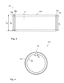
- the cooling sleeve 30 itself is with respect to the Figures 3 to 5 shown in detail.
- the cooling sleeve 30 shown is the cooling sleeve 30 of the first exemplary embodiment ( 1 ).
- the cooling sleeve 30 has an essentially cylindrical shape and is manufactured from one piece, for example by means of (CNC) turning, (CNC) milling, extrusion molding and/or rolling, in particular cold rolling.
- the cooling sleeve 30 has an outer diameter D4 that is slightly larger than the inner diameter D2 of the drum tube 2 to allow for an interference fit. In order to enable the cooling sleeve 30 to be installed, it is slotted axially and has a slot 42 .
- the slot has a width G, which can be in the range of 4 mm, for example.
- the width G depends on the wall thickness W of the cooling sleeve 30 and on the difference between the outer diameter D4 and the inner diameter D2 as well as the material of the cooling sleeve 30.
- the width G of the slot 42 should be dimensioned so that the cooling sleeve 30 can be joined into the Interior of the drum tube 2 is also possible taking into account maximum tolerances.
- the cooling sleeve 30 has assembly chamfers 44, 44a on both sides, each of which opens into a shoulder 46, 46a with a diameter D5.
- the diameter D5 is smaller than the diameter D4, for example about 4-6% smaller.
- the diameter D5 should be dimensioned in such a way that it is also slightly smaller than the diameter D2, so that the cooling sleeve 30 can initially be inserted into the interior of the drum tube 2 with the shoulder 46 without any problems and without applying a great deal of force before a radial compression of the cooling sleeve 30 takes place in order to then bring it completely into the interior of the drum tube 2 .
- the inclination of the chamfer 44 can be in the range of 60° to the central axis A, for example.
- the cooling sleeve can be pressed in in each of the two conceivable orientations, so that incorrect assembly is excluded and an alignment step of the cooling sleeve to press in a defined side of the cooling sleeve ahead can be omitted in automated assembly.
- Both the inner surface 34 and the outer surface 40 of the cooling sleeve 30 have a surface roughness of preferably Rz 30 or less, preferably Rz 25 or less. That is, both surfaces 34, 40 are preferably finished.
- the outer surface 40 should be formed in such a way that the most secure non-positive connection possible is achieved with the inner peripheral surface 32 of the drum tube 2 and at the same time the largest possible contact area in order to enable heat conduction from the cooling sleeve 30 to the drum tube 2.
- the inner surface 34 should be formed in such a way that it does not reflect, but allows heat radiation from the drive unit 14 to the cooling sleeve 30 to be as efficient as possible.
- the cooling sleeve 30 or alternatively the drum tube has a surface treatment 48 on the inner surface 34, for example a blue finish, an anodization or a colored layer, in particular with a dark color, in particular black, in order to absorb thermal radiation as well as possible and little thermal radiation reflect.
- a surface treatment 48 on the inner surface 34 for example a blue finish, an anodization or a colored layer, in particular with a dark color, in particular black, in order to absorb thermal radiation as well as possible and little thermal radiation reflect.
- the cooling sleeve 30 is preferably formed from a light metal.
- Aluminum is particularly useful here.
- Aluminum should be used here, which has a density of preferably 3 kg/dm3 or less and a thermal conductivity of preferably 130 W/mK or more. Suitable alloying metals can be added to the aluminum for this purpose.
- FIGS figures 1 and 2 already shown in section.
- the coupling unit 22 acts exclusively in a non-positive manner and is preferably installed together with the cooling sleeve 30 .
- This coupling unit 22 is in the German patent application DE 10 2016 124 689 described by the present applicant, the disclosure of which is fully incorporated herein.
- the coupling unit 22 has a coupling bushing 50 in whose central opening 74 a toothed shaft piece 51 can engage.
- the toothed shaft piece 51 is connected to the output of the gear 18 .
- the coupling socket 50 is designed in two parts and has a radially inner part 62 and a radially outer part 60 .
- the radially outer part 60 forms an output section 52 which is non-positively connected to the inner peripheral surface 32 of the drum tube 2 .
- the inner part 62 has a substantially cylindrical peripheral surface 92 on which the outer part 60 is applied in the form of a corrugated metal strip.
- the corrugated sheet metal strip of the outer portion 60 forms a plurality of tabs 54 which in this embodiment are hollow and define a cavity 94 therein. This provides the elasticity of the lugs 54 and manufacturing tolerances can be compensated for.
- the inner part 62 has projections 78 in which axial recesses 82 are provided. These axial recesses 82 serve on the one hand to reduce weight and on the other hand to make the projections 78 elastic in order to enable an elastic transmission of torque from the toothed shaft piece 51 to the inner part 62 .
- the corrugated sheet metal strip which forms the outer part 60, interacts both with the inner peripheral surface 32 and with the outer surface 92 of the inner part 62 in a non-positive manner. Due to the flexibility of the sheet metal strip, tolerances can be compensated and a permanent non-positive connection is provided. It is conceivable that the coupling sleeve 50 is pushed into the interior of the drum tube 2 by means of the cooling sleeve 30 . As a result, a further assembly tool for assembling the coupling bushing 50 can be saved, since the coupling bushing 50 is assembled in one step with the cooling sleeve 30 .
Landscapes
- Engineering & Computer Science (AREA)
- Mechanical Engineering (AREA)
- Power Engineering (AREA)
- Rollers For Roller Conveyors For Transfer (AREA)
- Rolls And Other Rotary Bodies (AREA)
- Connection Of Motors, Electrical Generators, Mechanical Devices, And The Like (AREA)
Applications Claiming Priority (3)
| Application Number | Priority Date | Filing Date | Title |
|---|---|---|---|
| DE102017121486.0A DE102017121486B4 (de) | 2017-09-15 | 2017-09-15 | Motorbetriebene Förderrolle mit in das Trommelrohr eingepresster Kühlhülse |
| PCT/EP2018/073849 WO2019052871A2 (fr) | 2017-09-15 | 2018-09-05 | Rouleau de transport entraîné par moteur avec manchon de refroidissement enfoncé dans le tube de tambour |
| EP18766191.3A EP3504137A2 (fr) | 2017-09-15 | 2018-09-05 | Rouleau de transport entraîné par moteur avec manchon de refroidissement enfoncé dans le tube de tambour |
Related Parent Applications (1)
| Application Number | Title | Priority Date | Filing Date |
|---|---|---|---|
| EP18766191.3A Division EP3504137A2 (fr) | 2017-09-15 | 2018-09-05 | Rouleau de transport entraîné par moteur avec manchon de refroidissement enfoncé dans le tube de tambour |
Publications (2)
| Publication Number | Publication Date |
|---|---|
| EP4230551A2 true EP4230551A2 (fr) | 2023-08-23 |
| EP4230551A3 EP4230551A3 (fr) | 2023-11-01 |
Family
ID=63528750
Family Applications (2)
| Application Number | Title | Priority Date | Filing Date |
|---|---|---|---|
| EP23159977.0A Pending EP4230551A3 (fr) | 2017-09-15 | 2018-09-05 | Rouleau de transport motorisé |
| EP18766191.3A Withdrawn EP3504137A2 (fr) | 2017-09-15 | 2018-09-05 | Rouleau de transport entraîné par moteur avec manchon de refroidissement enfoncé dans le tube de tambour |
Family Applications After (1)
| Application Number | Title | Priority Date | Filing Date |
|---|---|---|---|
| EP18766191.3A Withdrawn EP3504137A2 (fr) | 2017-09-15 | 2018-09-05 | Rouleau de transport entraîné par moteur avec manchon de refroidissement enfoncé dans le tube de tambour |
Country Status (8)
| Country | Link |
|---|---|
| US (1) | US11091321B2 (fr) |
| EP (2) | EP4230551A3 (fr) |
| JP (1) | JP6999803B2 (fr) |
| KR (1) | KR102379627B1 (fr) |
| CN (1) | CN111295347B (fr) |
| CA (1) | CA3074888C (fr) |
| DE (1) | DE102017121486B4 (fr) |
| WO (1) | WO2019052871A2 (fr) |
Families Citing this family (9)
| Publication number | Priority date | Publication date | Assignee | Title |
|---|---|---|---|---|
| CN111824695B (zh) * | 2019-04-17 | 2024-09-06 | 梅特勒-托利多安全线有限公司 | 用于输送机系统的驱动辊组件和包括它的输送机系统 |
| US20210097968A1 (en) | 2019-09-27 | 2021-04-01 | Dematic Corp. | Sound attenuation for material handling systems |
| IT202100004304A1 (it) * | 2021-02-24 | 2022-08-24 | Rulli Rulmeca S P A | Cartuccia motore per rullo, rullo. |
| CN115592754A (zh) * | 2022-10-25 | 2023-01-13 | 广西柯瑞机械设备有限公司(Cn) | 一种内置驱动压辊 |
| JP7795204B2 (ja) * | 2022-10-25 | 2026-01-07 | 株式会社協和製作所 | コンベア用モータ内蔵ローラおよびコンベア装置 |
| US11891252B1 (en) * | 2023-01-03 | 2024-02-06 | Dematic Corp. | Sound attenuated conveyor roller assembly |
| CN116054478A (zh) * | 2023-02-15 | 2023-05-02 | 深圳市兆威机电股份有限公司 | 张紧结构及滚筒电机 |
| WO2025065537A1 (fr) * | 2023-09-28 | 2025-04-03 | 德昌电机(江门)有限公司 | Rouleau à entraînement direct et dispositif transporteur du type rouleau |
| DE102023129620A1 (de) | 2023-10-26 | 2025-04-30 | Schindler Holding GmbH & Co. KG | Antriebseinheit und Zusammenstellung von Antriebseinheiten |
Citations (5)
| Publication number | Priority date | Publication date | Assignee | Title |
|---|---|---|---|---|
| DE2238562A1 (de) | 1972-08-04 | 1974-02-21 | Siemens Ag | Elektrische maschine |
| DE10324664A1 (de) | 2003-05-30 | 2004-12-30 | Siemens Ag | Rollen und Rollenmotoren |
| DE102006060009A1 (de) | 2006-12-19 | 2008-06-26 | Siemens Ag | Rollenantrieb für eine Förderanlage sowie Förderanlage |
| DE102008061979A1 (de) | 2008-12-12 | 2010-06-17 | Interroll Trommelmotoren Gmbh | Trommelmotor mit Innenläufer-Elektromotor und Wärmeleitkörper |
| DE102016124689A1 (de) | 2016-12-16 | 2018-06-21 | Interroll Holding Ag | Förderrolle mit reib- und/oder stoffschlüssiger Kupplungsbuchse |
Family Cites Families (20)
| Publication number | Priority date | Publication date | Assignee | Title |
|---|---|---|---|---|
| JPS566334Y2 (fr) * | 1975-07-04 | 1981-02-12 | ||
| JPS528882A (en) | 1975-07-11 | 1977-01-24 | Nippon Steel Corp | Machine cooler damage detector unit |
| US4130442A (en) | 1977-06-06 | 1978-12-19 | Frederick G. Schwarzmann | Method for renewing grout |
| JPS586807Y2 (ja) * | 1977-06-09 | 1983-02-05 | 京セラ株式会社 | ロ−ルの熱膨張吸収機構 |
| JPS60122615A (ja) | 1983-12-02 | 1985-07-01 | Toshiyuki Ishino | コンベア用のロ−ラ |
| DE19615709C2 (de) * | 1996-04-22 | 2001-11-08 | Heinz Joerissen | Trommelmotor |
| DE19651817C2 (de) | 1996-12-13 | 1999-05-12 | Daniel Knipping | Rohrpreßkupplung |
| JPH10304618A (ja) | 1997-04-22 | 1998-11-13 | Kyowa Seisakusho:Kk | モーターローラ |
| JP2002145438A (ja) * | 2000-11-13 | 2002-05-22 | Ito Denki Kk | モータ内蔵ローラ用ローラユニット |
| JP3600860B2 (ja) * | 2000-11-22 | 2004-12-15 | 伊東電機株式会社 | モータ内蔵ローラ及びモータ内蔵ローラ用のユニット |
| TWI282200B (en) | 2003-03-27 | 2007-06-01 | Sumitomo Heavy Industries | Cooling structure for roller of build-in motor |
| BE1016242A3 (fr) * | 2004-10-15 | 2006-06-06 | Dynaco International Sa | Dispositif avec un tambour dans lequel est monte un moteur d'entrainement. |
| KR101047643B1 (ko) * | 2004-12-16 | 2011-07-07 | 두산인프라코어 주식회사 | 전동기의 냉각구조 |
| KR20060068867A (ko) | 2004-12-17 | 2006-06-21 | 주식회사 팬택 | 이동통신단말기에서의 카메라 기능 제한 방법 |
| FI117936B (fi) | 2005-02-01 | 2007-04-30 | Sandvik Mining & Constr Oy | Hihnakuljetin ja hihnakuljettimen rumpumoottori |
| EP2492047A1 (fr) | 2011-02-28 | 2012-08-29 | Siemens Aktiengesellschaft | Unité d'enroulement de moteur dotée d'un entraînement direct sans boîtier |
| TWI565198B (zh) * | 2015-01-08 | 2017-01-01 | 周文三 | 可抑住馬達內部升溫之散熱構造 |
| DE102015201103A1 (de) | 2015-01-23 | 2016-07-28 | Schaeffler Technologies AG & Co. KG | Pressverbindungen von stanzpaketierten Bauteilen mit Wellen |
| DE102015006688A1 (de) * | 2015-05-28 | 2016-12-01 | Sew-Eurodrive Gmbh & Co Kg | Antriebsvorrichtung |
| TWI575853B (zh) | 2015-07-02 | 2017-03-21 | Wen-San Chou | 馬達之散熱構造 |
-
2017
- 2017-09-15 DE DE102017121486.0A patent/DE102017121486B4/de active Active
-
2018
- 2018-09-05 CN CN201880070321.5A patent/CN111295347B/zh active Active
- 2018-09-05 EP EP23159977.0A patent/EP4230551A3/fr active Pending
- 2018-09-05 CA CA3074888A patent/CA3074888C/fr active Active
- 2018-09-05 US US16/646,223 patent/US11091321B2/en not_active Expired - Fee Related
- 2018-09-05 WO PCT/EP2018/073849 patent/WO2019052871A2/fr not_active Ceased
- 2018-09-05 JP JP2020515214A patent/JP6999803B2/ja active Active
- 2018-09-05 EP EP18766191.3A patent/EP3504137A2/fr not_active Withdrawn
- 2018-09-05 KR KR1020207010870A patent/KR102379627B1/ko not_active Expired - Fee Related
Patent Citations (5)
| Publication number | Priority date | Publication date | Assignee | Title |
|---|---|---|---|---|
| DE2238562A1 (de) | 1972-08-04 | 1974-02-21 | Siemens Ag | Elektrische maschine |
| DE10324664A1 (de) | 2003-05-30 | 2004-12-30 | Siemens Ag | Rollen und Rollenmotoren |
| DE102006060009A1 (de) | 2006-12-19 | 2008-06-26 | Siemens Ag | Rollenantrieb für eine Förderanlage sowie Förderanlage |
| DE102008061979A1 (de) | 2008-12-12 | 2010-06-17 | Interroll Trommelmotoren Gmbh | Trommelmotor mit Innenläufer-Elektromotor und Wärmeleitkörper |
| DE102016124689A1 (de) | 2016-12-16 | 2018-06-21 | Interroll Holding Ag | Förderrolle mit reib- und/oder stoffschlüssiger Kupplungsbuchse |
Also Published As
| Publication number | Publication date |
|---|---|
| CA3074888C (fr) | 2022-12-06 |
| DE102017121486A1 (de) | 2019-03-21 |
| JP6999803B2 (ja) | 2022-02-10 |
| WO2019052871A3 (fr) | 2019-05-09 |
| US20200270065A1 (en) | 2020-08-27 |
| DE102017121486B4 (de) | 2019-05-23 |
| EP3504137A2 (fr) | 2019-07-03 |
| JP2020533252A (ja) | 2020-11-19 |
| KR102379627B1 (ko) | 2022-03-28 |
| EP4230551A3 (fr) | 2023-11-01 |
| KR20200053583A (ko) | 2020-05-18 |
| US11091321B2 (en) | 2021-08-17 |
| CN111295347B (zh) | 2021-09-07 |
| BR112020004779A2 (pt) | 2020-09-24 |
| CN111295347A (zh) | 2020-06-16 |
| WO2019052871A2 (fr) | 2019-03-21 |
| CA3074888A1 (fr) | 2019-03-21 |
Similar Documents
| Publication | Publication Date | Title |
|---|---|---|
| DE102017121486B4 (de) | Motorbetriebene Förderrolle mit in das Trommelrohr eingepresster Kühlhülse | |
| EP3212543B1 (fr) | Dispositif de transport destiné à une installation de transport, système modulaire et procédé de fabrication dudit dispositif de transport | |
| EP2241781B2 (fr) | Engrenage, notamment train épicycloïdal doté d'une bride et d'une roue creuse | |
| EP3277981B1 (fr) | Actionneur muni d'une vis d'entraînement à roulement planétaire (pwg) | |
| DE102013101256A1 (de) | Antriebseinheit | |
| DE1951427C3 (de) | Ins Langsame übersetzendes Getriebe | |
| DE112015005185T5 (de) | Antriebskraftübertragungsvorrichtung | |
| DE102016124689A1 (de) | Förderrolle mit reib- und/oder stoffschlüssiger Kupplungsbuchse | |
| EP1704104A2 (fr) | Support de rotation muni d'un dispositif d'assemblage elastique pour monter des machines electriques dans des tuyaux | |
| EP2778100B1 (fr) | Rouleau de manutention avec raidisseur | |
| DE69819826T2 (de) | Servosteuersystem | |
| DE1763230B2 (de) | Doppelt isolierter elektromotor | |
| EP3208164A1 (fr) | Vis d'entrainement a bille | |
| DE3909910C2 (fr) | ||
| DE2409149C3 (de) | Schraubengetriebe | |
| EP2897887B1 (fr) | Rouleau de transport muni d'un élément de raccordement | |
| DE102006005580B4 (de) | Linearbewegungs- und Drehstellglied | |
| DE102006005043B4 (de) | Kraftübertragungsvorrichtung | |
| DE102006060009B4 (de) | Rollenantrieb für eine Förderanlage sowie Förderanlage | |
| EP3641983B1 (fr) | Plateau rotatif comprenant un entraînement optimisé en force | |
| DE102015105543A1 (de) | Getriebekühlung | |
| EP1610987A1 (fr) | Unite d'entrainement electrique | |
| EP2565364A2 (fr) | Adaptateur pour l'arbre entraîné d'un dispositif d'entraînement tubulaire pour enrouler et dérouler un dispositif d'assombrissement, en particulier un store ou analogue | |
| DE102013110998B4 (de) | Elektromotor in Form eines Außenläufermotors | |
| DE102008016909B4 (de) | Rollosystem |
Legal Events
| Date | Code | Title | Description |
|---|---|---|---|
| PUAI | Public reference made under article 153(3) epc to a published international application that has entered the european phase |
Free format text: ORIGINAL CODE: 0009012 |
|
| STAA | Information on the status of an ep patent application or granted ep patent |
Free format text: STATUS: THE APPLICATION HAS BEEN PUBLISHED |
|
| AC | Divisional application: reference to earlier application |
Ref document number: 3504137 Country of ref document: EP Kind code of ref document: P |
|
| AK | Designated contracting states |
Kind code of ref document: A2 Designated state(s): AL AT BE BG CH CY CZ DE DK EE ES FI FR GB GR HR HU IE IS IT LI LT LU LV MC MK MT NL NO PL PT RO RS SE SI SK SM TR |
|
| PUAL | Search report despatched |
Free format text: ORIGINAL CODE: 0009013 |
|
| AK | Designated contracting states |
Kind code of ref document: A3 Designated state(s): AL AT BE BG CH CY CZ DE DK EE ES FI FR GB GR HR HU IE IS IT LI LT LU LV MC MK MT NL NO PL PT RO RS SE SI SK SM TR |
|
| RIC1 | Information provided on ipc code assigned before grant |
Ipc: H02K 9/00 20060101ALI20230925BHEP Ipc: H02K 7/10 20060101ALI20230925BHEP Ipc: B65G 23/08 20060101AFI20230925BHEP |
|
| STAA | Information on the status of an ep patent application or granted ep patent |
Free format text: STATUS: REQUEST FOR EXAMINATION WAS MADE |
|
| 17P | Request for examination filed |
Effective date: 20240417 |
|
| RBV | Designated contracting states (corrected) |
Designated state(s): AL AT BE BG CH CY CZ DE DK EE ES FI FR GB GR HR HU IE IS IT LI LT LU LV MC MK MT NL NO PL PT RO RS SE SI SK SM TR |
|
| STAA | Information on the status of an ep patent application or granted ep patent |
Free format text: STATUS: EXAMINATION IS IN PROGRESS |
|
| 17Q | First examination report despatched |
Effective date: 20260212 |