EP4230552A1 - Dispositif de séparation pour convoyeur aérien - Google Patents
Dispositif de séparation pour convoyeur aérien Download PDFInfo
- Publication number
- EP4230552A1 EP4230552A1 EP23156547.4A EP23156547A EP4230552A1 EP 4230552 A1 EP4230552 A1 EP 4230552A1 EP 23156547 A EP23156547 A EP 23156547A EP 4230552 A1 EP4230552 A1 EP 4230552A1
- Authority
- EP
- European Patent Office
- Prior art keywords
- separating
- elements
- holding
- pinion teeth
- separating element
- Prior art date
- Legal status (The legal status is an assumption and is not a legal conclusion. Google has not performed a legal analysis and makes no representation as to the accuracy of the status listed.)
- Pending
Links
Images


Classifications
-
- B—PERFORMING OPERATIONS; TRANSPORTING
- B65—CONVEYING; PACKING; STORING; HANDLING THIN OR FILAMENTARY MATERIAL
- B65G—TRANSPORT OR STORAGE DEVICES, e.g. CONVEYORS FOR LOADING OR TIPPING, SHOP CONVEYOR SYSTEMS OR PNEUMATIC TUBE CONVEYORS
- B65G47/00—Article or material-handling devices associated with conveyors; Methods employing such devices
- B65G47/22—Devices influencing the relative position or the attitude of articles during transit by conveyors
- B65G47/26—Devices influencing the relative position or the attitude of articles during transit by conveyors arranging the articles, e.g. varying spacing between individual articles
- B65G47/28—Devices influencing the relative position or the attitude of articles during transit by conveyors arranging the articles, e.g. varying spacing between individual articles during transit by a single conveyor
-
- B—PERFORMING OPERATIONS; TRANSPORTING
- B65—CONVEYING; PACKING; STORING; HANDLING THIN OR FILAMENTARY MATERIAL
- B65G—TRANSPORT OR STORAGE DEVICES, e.g. CONVEYORS FOR LOADING OR TIPPING, SHOP CONVEYOR SYSTEMS OR PNEUMATIC TUBE CONVEYORS
- B65G17/00—Conveyors having an endless traction element, e.g. a chain, transmitting movement to a continuous or substantially-continuous load-carrying surface or to a series of individual load-carriers; Endless-chain conveyors in which the chains form the load-carrying surface
- B65G17/20—Conveyors having an endless traction element, e.g. a chain, transmitting movement to a continuous or substantially-continuous load-carrying surface or to a series of individual load-carriers; Endless-chain conveyors in which the chains form the load-carrying surface comprising load-carriers suspended from overhead traction chains
-
- B—PERFORMING OPERATIONS; TRANSPORTING
- B65—CONVEYING; PACKING; STORING; HANDLING THIN OR FILAMENTARY MATERIAL
- B65G—TRANSPORT OR STORAGE DEVICES, e.g. CONVEYORS FOR LOADING OR TIPPING, SHOP CONVEYOR SYSTEMS OR PNEUMATIC TUBE CONVEYORS
- B65G47/00—Article or material-handling devices associated with conveyors; Methods employing such devices
- B65G47/74—Feeding, transfer, or discharging devices of particular kinds or types
- B65G47/84—Star-shaped wheels or devices having endless travelling belts or chains, the wheels or devices being equipped with article-engaging elements
- B65G47/846—Star-shaped wheels or wheels equipped with article-engaging elements
Definitions
- the invention relates to a separating device according to claim 1, a system with such a separating device according to claim 7 and a method for separating according to claim 10.
- a conveyor device for transporting hanging objects is a sorting and distribution device and plays an important role in intralogistics, where it is often used as an interface between storage and delivery.
- the conveyor devices are subject to constant further development, especially with regard to process reliability and efficiency.
- Generic conveyor devices have rail profiles on which holding adapters are mounted and guided.
- the holding adapters which are preferably equipped with rollers, are mounted and guided in particular in a lower area of the rail profile, in particular in a so-called free running rail.
- the hanging objects are detachably fastened to the holding adapters, preferably below the free running rail.
- a conveyor chain of the conveyor device is arranged in the rail profiles, with which the holding adapters can be coupled for their transport.
- carriers of the conveyor chain act in particular on a head part of the holding adapter, which preferably extends into an area of the rail profile located above the free running rail.
- Isolation devices In order to generate distances between the holding adapters or objects attached to them before decision points or applications of the conveyor device and thus to separate the holding adapters or objects attached to them for process-reliable further processing at the decision points or applications, so-called Isolation devices provided.
- separating devices are based on a linear movement of a single elongate or rod-shaped separating element, which can be displaced into a conveyor path for the holding adapter.
- separating devices have the disadvantage that the separating element has to be moved back into a starting position again and again after a separating process. With such a separating device, it can also happen that the holding adapter stops in the separating device, that is to say is not conveyed further, and the operating sequence is thus disrupted.
- such separating devices are usually operated with a pneumatic cylinder. However, the use of pneumatics in conveyor devices for transporting hanging objects is no longer permitted.
- a diverter of a collecting conveyor for goods hanging on hangers is also known, to which hangers are conveyed from two directions and which do not represent separating devices.
- Two chain-driven discs with carriers are provided on the points for the onward transport of the brackets.
- One disk conveys the hangers coming from a first direction and the other disk conveys the hangers coming from a second direction.
- the carriers of the two discs are designed as carrier pawls or pin carriers.
- the drivers of one disk work with a rotational offset to the drivers of the other disk.
- the catches on one pane overlap the other pane and vice versa.
- the switch analogous to that of the DE 202 17 423 U1 is formed and also does not represent a separation device.
- the switch includes four star wheels, with which the unstable objects are transported further. The object is transferred from one star wheel to the other on a pair of star wheels, with the two star wheels being rotatably mounted for this purpose in different planes and acting on the object in different planes. On another pair of star wheels, the arms of one star wheel operate with a rotational offset to the arms of the other star wheel.
- the object of the present invention is to provide a separating device, a system with such a separating device and to provide a method for separation with which a process-reliable separation can take place.
- a separating device for separating holding adapters in a conveyor device for transporting hanging objects having two separating elements, which are each designed as a disk with a plurality of driver elements designed as pinion teeth and which are rotatably mounted in opposite directions to one another in one plane and are thus spaced apart from one another are arranged such that holding adapters can be conveyed through the separating elements, pinion teeth being provided as driver elements and, in a possible rotational position of the separating elements, a pinion tooth of the first separating element and a pinion tooth being located on an imaginary line between a rotational axis of a first separating element and a rotational axis of a second separating element of the second separating element face each other with their end faces.
- the separating elements of the separating device also referred to as a separating device, are designed as a disk and are therefore flat and are provided with pinion teeth which are suitable for engaging on the holding adapters arranged between the separating elements.
- the separating elements formed in this way can also be referred to as star-shaped due to their appearance. Both separating elements preferably have the same number of pinion teeth.
- the term holding adapter is understood to mean both an empty holding adapter and a holding adapter with an object attached to it.
- the holding adapter which is preferably mounted such that it can be rolled, has in particular an engagement element, on which the separating elements or their pinion teeth engage for entrainment.
- Such an attack element is in particular on a neck part of the Arranged holding adapter or formed by the neck part of the holding adapter.
- the engagement element or the neck part is arranged in particular below a rail profile or below a free running rail of the rail profile.
- Rotatably mounted in opposite directions means that the first separating element is rotatably mounted in a first direction of rotation, for example clockwise, and the second separating element is rotatably mounted in a second direction of rotation directed opposite to the first direction of rotation, for example counterclockwise.
- the separating elements are rotatably mounted in one plane, which means that the axis of rotation of the first separating element differs from the axis of rotation of the second separating element.
- the separating elements in particular their axes of rotation, are arranged so far apart from one another that, in a top view, a pinion tooth of the first separating element cannot overlap with the second separating element and vice versa.
- the separating elements are arranged so close together that in the possible rotational position of the separating elements, in which on the imaginary line between the axis of rotation of the first separating element and the axis of rotation of the second separating element, a pinion tooth of the first separating element and a pinion tooth of the second separating element face each other with their end faces stand, no holding adapter, in particular no attack element of the holding adapter fits through between the opposing pinion teeth. In this position, the holding adapter is stopped and held at the opposing pinion teeth. This prevents a holding adapter from slipping through unintentionally. Further transport of the holding adapter is only possible when the separating elements are rotated out of this rotational position.
- the separating elements are arranged on both sides of a conveyor section, formed in particular by rail profiles, along which the holding adapters are transported.
- the separating elements are arranged mirror-symmetrically in relation to the conveyor section. In the separating device according to the invention so there is no rotational offset between the Pinion teeth of the first separating element and the pinion teeth of the second separating element are provided.
- the separating device has only a single separating element, which is designed as a disk with a plurality of carrier elements designed as pinion teeth.
- a separating device then comprises, in addition to the individual separating element, a flat counter-support element, in particular designed as a counter-support plate.
- the separating element and the counter-retaining element are arranged in such a way that, in a possible rotational position of the separating element, the end face of a pinion tooth of the separating element is opposite the counter-retaining surface on an imaginary line that runs orthogonally to a counter-retaining surface of the counter-retaining element and intersects the axis of rotation of the separating element.
- the separating device is arranged in front of one, several or all decision points or applications of the conveyor device, in particular when viewed in the conveying direction.
- the separating device is arranged behind a section of the conveyor device that generates a jam, in particular an accumulation conveyor or an incline, as viewed in the conveying direction.
- the separating device according to the invention Using the separating device according to the invention, the use of pneumatics is not necessary.
- the separating device according to the invention enables increased process reliability compared to a separating device with a linearly movable separating element, since the passage of more than one holding adapter can be ruled out.
- the separating device according to the invention also has the advantage that it can run endlessly in one direction and therefore does not have to complete a cycle for separating, ie no time is required for returning the separating element to a starting position. Compared to the known separating device, a higher throughput of the separating device and thus a higher output of the conveying device can thus be achieved. The maintenance effort is also lower than with the known solution.
- a front flank of at least one of the pinion teeth is steeper than a rear flank of the same pinion tooth.
- Each pinion tooth of each of the two separating elements is preferably provided with flanks designed in this way.
- the front steep flank of the pinion tooth is used to push or push out the holding adapter from the separating device.
- the holding adapter can be accelerated when leaving the separating device to a speed which, in particular, is equal to that of a conveyor or pull-off conveyor provided downstream of the separating device in the conveying direction.
- the rear, flatter flank of the pinion tooth serves to smoothly accommodate the holding adapter or its engaging element.
- the shape of the pinion teeth is thus designed such that a collision of the separating elements with a holding adapter to be received, in particular with its engaging element, is avoided, in particular that the holding adapter or its engaging element is not clamped between the pinion teeth of the two separating elements.
- the two separating elements are connected to one another via force-transmitting and/or speed-transmitting connecting elements.
- the connecting elements preferably include a shaft to which one of the separating elements is connected.
- the connecting elements can also include a plurality of shafts, in which case, for example, the first separating element can be connected to a first shaft and the second separating element can be connected to a second shaft.
- the connecting elements can include, for example, a coupling element, in particular a shaft coupling.
- the connecting elements include a gear with a Transmission ratio of preferably 1:1.
- the transmission has in particular two gear wheels, each of the gear wheels being connected to a separating element.
- the first and the second separating element are connected in such a way that the first separating element is connected to a first shaft and the first shaft is connected to a first gear wheel of the transmission, the first gear wheel with a gear ratio of 1: 1 engages in a second gear wheel of the transmission and the second gear wheel is connected to a second shaft and the second shaft is connected to the second separating element.
- the separating device can advantageously be made for the separating device to have a housing for mounting at least one of the separating elements, with the separating element preferably being mounted on the housing by means of a roller bearing, in particular a ball bearing. Both separating elements can also be mounted on the housing.
- one of the separating elements is connected to a shaft, provision can be made, for example, for the separating element to be mounted on the housing via the shaft, which is then preferably mounted on the housing by means of two ball bearings.
- the separating device comprises a rotating actuator, preferably an electric motor, preferably a stepper motor, it being possible for the actuator to cause at least one of the separating elements to rotate.
- the rotating actuator is to be distinguished in particular from a drive chain or a drive belt.
- the actuator can be connected to a shaft, which in turn is connected to the separating element, for example by means of a coupling element. It is also conceivable that the actuator is alternatively or additionally connected to the separating element by means of a deflection gear, in particular a bevel gear.
- the separating element can also be in one desired position can be held, which means that the actuator can apply a counterforce to a force caused by, in particular dammed up, holding adapters.
- the actuator can apply a counterforce to a force caused by, in particular dammed up, holding adapters.
- this is designed and set up in particular such that the separating element is rotated further by a predetermined angle of rotation or a pinion tooth each time the stepping motor is activated, and the separating element is held in position between activations.
- a rotation of both separating elements can preferably be brought about with a single actuator, the separating elements then being connected to one another via connecting elements for this purpose.
- the separating device can be controlled via a central control of the conveyor device or alternatively via a separate control unit assigned to the separating device.
- the invention is also directed to a system with holding adapters and a separating device according to the invention, the pinion teeth being arranged relative to one another in such a way that in a region formed by two adjacent pinion teeth of the first separating element and two adjacent pinion teeth of the second separating element, only a single holding adapter, in particular a single Attack element of a holding adapter that finds space.
- a region is thus formed or spanned by the distance between two adjacent pinion teeth on the first separating element and the distance between two adjacent pinion teeth on the second separating element and the arrangement of the two separating elements with respect to one another. Only a single holding adapter or its engagement element fits into this area, so that during a separating process only one holding adapter can be “released” by the separating device.
- the area is optimized by the shape of the pinion teeth in terms of smooth accommodation of the holding adapter or its engaging element, with a front flank of at least one of the pinion teeth being steeper than a rear flank as viewed in the direction of rotation of the respective separating element same pinion tooth.
- the separating device With the separating device according to the invention it can thus be ensured that only one holding adapter is separated in each case. It is therefore possible to dispense with sensor technology for checking that only one holding adapter in each case comes through the separating device during a separating process.
- a sensor can be provided which detects whether there is a holding adapter at all in the area also referred to as the separation area.
- the data from such a sensor could be used for targeted control of the separating elements.
- the system advantageously includes a rail profile for mounting and guiding the holding adapter, each of the two separating elements being connected to a shaft and the shafts being arranged on both sides of the rail profile.
- a shaft connected to the first separating element is then arranged on one side of the rail profile, for example on the right when viewed in the conveying direction, and a shaft connected to the second separating element is arranged on the other side of the rail profile, for example on the left when viewed in the conveying direction.
- the housing of the separating device at least partially encompasses the rail profile.
- Partial encompassing means that the housing is arranged on and next to the rail profile or under and next to the rail profile. It is also possible for the housing to completely enclose the rail profile and then to be arranged next to, on and below the rail profile, with an area for transporting the holding adapter remaining free even if the housing is completely encircled.
- the housing can also be designed in such a way that it is only arranged on the rail profile or next to the rail profile or under the rail profile.
- the invention also relates to a method for separating holding adapters in a conveyor device for conveying hanging objects. Separation takes place by means of a separating device with two separating elements, which are each designed as a disk with several driver elements designed as pinion teeth and which are rotatably mounted in opposite directions to one another in one plane and are arranged on both sides of a conveyor line with holding adapters to be separated.
- the method according to the invention provides that the pinion teeth are arranged relative to one another in such a way that in a region formed by two adjacent pinion teeth of a first separating element and two adjacent pinion teeth of a second separating element, there is only room for a single holding adapter, in particular the engagement element of the single holding adapter, and the Separating elements are rotated in opposite directions to one another by a predetermined angle of rotation in order to separate the individual holding adapter from a group of holding adapters, in particular a accumulated one, and thus to separate it.
- two separating elements arranged on both sides of the conveyor line formed in particular by a rail profile are rotated simultaneously or synchronously by a predetermined angle of rotation in order to separate a holding adapter and thus carry out a separating process.
- the predetermined angle of rotation by which the separating elements are rotated during each separating process results from the number of pinion teeth.
- a separating process corresponds in particular to a rotation angle of 360° divided by the number of pinion teeth on one of the separating elements. In other words, the separating elements are rotated further by one pinion tooth for each separation.
- a holding adapter lying at the front in the conveying direction is pushed out or pushed out by means of the separating elements on an output side of the separating device. Because between the pinion teeth of the first separating element and the pinion teeth of the second If no offset is provided for the separating element, the pressing out or pushing out takes place with a pinion tooth of each of the two separating elements that acts on the holding adapter.
- a front flank of at least one of the pinion teeth is preferably steeper than a rear flank of the same pinion tooth.
- the separating device used for the method preferably includes a rotating actuator, with which the rotation of the separating elements is brought about.
- the method according to the invention it is possible to create a defined distance between holding adapters that are fed to the separating device, in particular due to the upstream section that creates a jam, in a group without a distance from one another or with an undefined and possibly varying distance from one another, so that the Holding adapters can be handled individually and thus reliably at the downstream decision points or applications of the conveyor device.
- the defined distance is preferably constant over a certain number of holding adapters.
- the distance for each pair of adjacent holding adapters to be defined individually, that is to say it can be designed to be variable.
- the separating elements only have to be rotated in one direction. It is not necessary to return the separating element to a starting position.
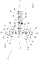
- FIG. 1 a sectional view of four holding adapters 20 and a schematic plan view of an embodiment of the separating device 1 according to the invention are shown at a first point in time.
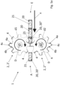
- FIG. 12 shows a sectional view of four holding adapters 20 and a schematic top view of the embodiment of the separating device 1.
- the separating device 1 has two disk-shaped separating elements 2, which are mounted in one plane and each can be rotated in opposite directions about an axis of rotation D.
- a first separating element 2′ is rotatably mounted in a first direction of rotation d1 or clockwise and a second separating element 2′′ in a second direction of rotation d2 or counterclockwise.
- the separating elements 2 are arranged in a mirror-symmetrical manner on both sides of a conveying path which is provided for conveying holding adapters 20 .
- the conveying direction x runs in such a way that it "harmonizes" with the first direction of rotation d1 and the second direction of rotation d2.
- the separating elements 2 have driver elements which are designed as pinion teeth 4 .
- the pinion teeth 4 are suitable for taking along the holding adapter 20 , in particular by engaging with an engaging element 21 of the holding adapter 20 .
- both separating elements 2 each have eight pinion teeth 4.
- a pinion tooth 4 of the first separating element 2' and a pinion tooth 4 of the second separating element 2' and a pinion tooth 4 of the second Separating element 2 are opposite with their end faces 4c.
- the four holding adapters 20 (see figure 1 ) or the three holding adapters (see Figure 1a ) are accumulated in a group at the points in time shown on the pinion teeth 4 arranged in this way on an input side E of the separating device 1 .
- the separating elements 2 are rotated in opposite directions to one another at the same time or synchronously by a predetermined angle of rotation in order to move the first holding adapter 20' lying at the front in the conveying direction (see figure 1 ) or second holding adapter 20" (see Figure 1a ) from the accumulated group of holding adapters 20 and separate them and thus carry out a first separation process.
- the predetermined angle of rotation by which the separating elements 2 are rotated during each separating process results from the number of pinion teeth 4.
- a separating process corresponds in particular to a rotation angle of 360° divided by the number of pinion teeth 4 on one of the separating elements.
- the angle of rotation is 360° divided by eight pinion teeth 4 equal to 45°.
- the first holding adapter 20' is already isolated. Like in the Figure 1a can be seen, the following second holding adapter 20" is held on the pinion teeth 4, in particular on the same pinion teeth 4 with which the first holding adapter 20' was previously pushed out or pushed out. The second holding adapter 20" is then already in the area between the separating elements 2 added.
- FIG 2 a schematic perspective view of a system with an embodiment of the separation device 1 according to the invention is shown.
- FIG 3 is a combined side and sectional view of the system figure 2 shown.
- the system includes a rail profile 101 and four holding adapters 20, which are mounted and guided in the rail profile 101.
- the holding adapters 20 each have an engagement element 21 which is formed in the present case by a neck part of the holding adapter 20 which is arranged below the rail profile 101 .
- the separating device 1 has an actuator 9, a deflection gear 12, a shaft coupling 7, a gear 5, a housing 8 and a first shaft 6' and a second shaft 6''.
- the actuator 9 is designed as an electric motor, more precisely as a stepping motor.
- the first shaft 6 ′ is driven by the actuator 9 , the deflection gear 12 and the shaft coupling 7 being arranged between the first shaft 6 ′ and the actuator 9 .
- the shaft coupling 7 comprises two coupling elements 7a, one of the coupling elements 7a being connected to the first shaft 6' and the other coupling element 7a being connected to an output shaft of the deflection gear 12.
- the last-mentioned coupling element 7a can also be connected directly to the actuator 9, in particular to its rotor.
- the housing 8 is arranged on the rail profile.
- the actuator 9 and the deflection gear 12 are attached to the housing 8 via an L-shaped bracket 11 .
- the console 11 is fastened by means of a screw connection.
- any other type of connection such as a positive connection, is also possible.
- the gear 5 has two gear wheels 5a of the same size and with the same teeth, which mesh with one another. In the present case, the transmission 5 thus has a transmission ratio of 1:1.
- the gear wheels 5a are arranged outside of the housing 8 in the embodiment shown. It is conceivable that these are alternatively arranged inside the housing 8 .
- the first shaft 6' is connected to one of the gear wheels 5a and also to the first (not visible) separating element 2'.
- the second shaft 6" is connected to the other gear wheel 5a and also to the second separating element 2".
- the first separating element 2' and the second separating element 2'' have the pinion teeth 4 according to the invention.
- Both shafts 6 are each mounted on the housing 8 via two ball bearings 10 .
- the bearing of the second shaft 6" is clearly visible.
- the ball bearings 10 are arranged at a distance from one another.
- the first shaft 6 ⁇ which cannot be seen, is in similarly mounted on the housing 8.
- the shafts 6 are arranged on both sides of the rail profile 101. However, only the second shaft 6" can be seen in the illustration. The first shaft 6' cannot be seen, since it is covered by the rail profile 101.
- FIG 4 a schematic perspective view of a system with a further embodiment of the separation device 1 according to the invention is shown.
- the figure 5 is a combined side and sectional view of the system figure 4 shown.
- the in the Figures 4 and 5 shown embodiment differs from that in FIGS Figures 2 and 3 Embodiment shown by the formation of the housing 8. While the housing 8 in the Figures 2 and 3 shown embodiment is arranged on the rail profile 101, the housing 8 is in the Figures 4 and 5 shown embodiment, arranged next to and under the rail profile 101 and thus completely surrounds it. Alternatively, embodiments are also conceivable in which the housing 8 only partially surrounds the rail profile 101 .
- the two ball bearings 10 are arranged at a greater distance from each other.
Landscapes
- Engineering & Computer Science (AREA)
- Mechanical Engineering (AREA)
- Special Conveying (AREA)
- Specific Conveyance Elements (AREA)
Applications Claiming Priority (1)
| Application Number | Priority Date | Filing Date | Title |
|---|---|---|---|
| DE102022103809.2A DE102022103809A1 (de) | 2022-02-17 | 2022-02-17 | Vereinzelungsvorrichtung für Hängeförderanlage |
Publications (1)
| Publication Number | Publication Date |
|---|---|
| EP4230552A1 true EP4230552A1 (fr) | 2023-08-23 |
Family
ID=85238948
Family Applications (1)
| Application Number | Title | Priority Date | Filing Date |
|---|---|---|---|
| EP23156547.4A Pending EP4230552A1 (fr) | 2022-02-17 | 2023-02-14 | Dispositif de séparation pour convoyeur aérien |
Country Status (3)
| Country | Link |
|---|---|
| US (1) | US20230257210A1 (fr) |
| EP (1) | EP4230552A1 (fr) |
| DE (1) | DE102022103809A1 (fr) |
Citations (10)
| Publication number | Priority date | Publication date | Assignee | Title |
|---|---|---|---|---|
| DE2913446A1 (de) * | 1979-04-04 | 1980-10-16 | Alcoa Gmbh Masch | Flaschenteiler |
| JPH0336118A (ja) * | 1989-07-03 | 1991-02-15 | Kao Corp | 物品の送り出し装置 |
| US5501552A (en) | 1994-04-29 | 1996-03-26 | Goldco Industries, Inc. | Conveying system for unstable articles having a neck ring |
| US6109422A (en) * | 1995-12-05 | 2000-08-29 | Wf Logistik Gmbh | Conveyor device |
| DE20217423U1 (de) | 2002-11-12 | 2003-02-27 | Ramsbrock, Torsten, 32107 Bad Salzuflen | Sammelförderer mit Aufgabeweiche |
| US7735629B2 (en) * | 2007-11-15 | 2010-06-15 | B&H Manufacturing Company, Inc. | Star wheel system with passive star wheel and method for separating containers being processed |
| JP2014080266A (ja) * | 2012-10-16 | 2014-05-08 | Fabrica Toyama Corp | 物品切り離し装置 |
| US20150239671A1 (en) * | 2014-02-24 | 2015-08-27 | Dürkopp Fördertechnik GmbH | Transport system and method for transporting hanging goods |
| DE102014103632A1 (de) * | 2014-03-17 | 2015-09-17 | Krones Ag | Vorrichtung und Verfahren zum Transport von Behältern in einer Behälterbehandlungsanlage |
| US20220001423A1 (en) * | 2018-11-23 | 2022-01-06 | Intravis Gesellschaft Für Lieferungen Und Leistungen Von Bildgebenden Und Bildverarbeitenden Anlagen | Separating device of an optical testing unit |
-
2022
- 2022-02-17 DE DE102022103809.2A patent/DE102022103809A1/de active Pending
-
2023
- 2023-02-14 EP EP23156547.4A patent/EP4230552A1/fr active Pending
- 2023-02-16 US US18/170,494 patent/US20230257210A1/en active Pending
Patent Citations (10)
| Publication number | Priority date | Publication date | Assignee | Title |
|---|---|---|---|---|
| DE2913446A1 (de) * | 1979-04-04 | 1980-10-16 | Alcoa Gmbh Masch | Flaschenteiler |
| JPH0336118A (ja) * | 1989-07-03 | 1991-02-15 | Kao Corp | 物品の送り出し装置 |
| US5501552A (en) | 1994-04-29 | 1996-03-26 | Goldco Industries, Inc. | Conveying system for unstable articles having a neck ring |
| US6109422A (en) * | 1995-12-05 | 2000-08-29 | Wf Logistik Gmbh | Conveyor device |
| DE20217423U1 (de) | 2002-11-12 | 2003-02-27 | Ramsbrock, Torsten, 32107 Bad Salzuflen | Sammelförderer mit Aufgabeweiche |
| US7735629B2 (en) * | 2007-11-15 | 2010-06-15 | B&H Manufacturing Company, Inc. | Star wheel system with passive star wheel and method for separating containers being processed |
| JP2014080266A (ja) * | 2012-10-16 | 2014-05-08 | Fabrica Toyama Corp | 物品切り離し装置 |
| US20150239671A1 (en) * | 2014-02-24 | 2015-08-27 | Dürkopp Fördertechnik GmbH | Transport system and method for transporting hanging goods |
| DE102014103632A1 (de) * | 2014-03-17 | 2015-09-17 | Krones Ag | Vorrichtung und Verfahren zum Transport von Behältern in einer Behälterbehandlungsanlage |
| US20220001423A1 (en) * | 2018-11-23 | 2022-01-06 | Intravis Gesellschaft Für Lieferungen Und Leistungen Von Bildgebenden Und Bildverarbeitenden Anlagen | Separating device of an optical testing unit |
Also Published As
| Publication number | Publication date |
|---|---|
| DE102022103809A1 (de) | 2023-08-17 |
| US20230257210A1 (en) | 2023-08-17 |
Similar Documents
| Publication | Publication Date | Title |
|---|---|---|
| EP0795497B1 (fr) | Système de transport pour séparer des articles | |
| EP0633212A1 (fr) | Dispositif de transport circulant sans fin pour charge isolée avec organes de transport individuels | |
| EP3786089A1 (fr) | Dispositif et procédé de transport et de tri des marchandises de détail | |
| EP0345585A2 (fr) | Dispositif de transport pour des bonbons | |
| DE4211658A1 (de) | Vorschubeinrichtung für Tafeln | |
| EP3642140B1 (fr) | Dispositif de transport avec chariots déplaçables sur un rail | |
| DE102012109316A1 (de) | Übergabevorrichtung sowie Transportvorrichtung für Güter sowie Verfahren zum Betreiben einer Transportvorrichtung | |
| EP2687464B1 (fr) | Convoyeur à accumulation | |
| EP1042206B1 (fr) | Dispositif pour recevoir et/ou distribuer des produits plats | |
| EP2478782B1 (fr) | Dispositif de transport pour produits en forme de tige de l'industrie de traitement du tabac | |
| EP1670706B1 (fr) | Dispositif de formation de piles | |
| WO2022122792A2 (fr) | Dispositif d'éjection | |
| CH677778A5 (fr) | ||
| EP3433191A1 (fr) | Dispositif de support et arbre à cames pour dispositifs de préhension | |
| EP4230552A1 (fr) | Dispositif de séparation pour convoyeur aérien | |
| DE4345160A1 (de) | Vorrichtung zur Richtungsumkehr von flachen Sendungen | |
| EP0400295B1 (fr) | Dispositif pour convoyer et séparer des objets | |
| DE10126876B4 (de) | Verfahren und Vorrichtung zum Sortieren von Stückgütern | |
| EP2055660A1 (fr) | Dispositif de retournement cadencé d'objets plats | |
| EP3693299B1 (fr) | Dispositif de transport continu des marchandises transportées et procédé de transport continu des marchandises | |
| EP4029811A1 (fr) | Bande transporteuse destinée au transport des marchandises à transporter et ligne d'emballage d'une installation d'emballage doté d'une telle bande transporteuse | |
| DE102021125587B3 (de) | Vorrichtung und Verfahren zum Ausrichten von Würsten | |
| EP1274640A1 (fr) | Dispositif pour le transport d'objets | |
| EP3533731A1 (fr) | Transporteur incliné | |
| EP3600712B1 (fr) | Installation de dressage de fils et procédé pour le dressage de fils au moyen de l'installation de dressage de fils |
Legal Events
| Date | Code | Title | Description |
|---|---|---|---|
| PUAI | Public reference made under article 153(3) epc to a published international application that has entered the european phase |
Free format text: ORIGINAL CODE: 0009012 |
|
| STAA | Information on the status of an ep patent application or granted ep patent |
Free format text: STATUS: THE APPLICATION HAS BEEN PUBLISHED |
|
| AK | Designated contracting states |
Kind code of ref document: A1 Designated state(s): AL AT BE BG CH CY CZ DE DK EE ES FI FR GB GR HR HU IE IS IT LI LT LU LV MC ME MK MT NL NO PL PT RO RS SE SI SK SM TR |
|
| STAA | Information on the status of an ep patent application or granted ep patent |
Free format text: STATUS: REQUEST FOR EXAMINATION WAS MADE |
|
| 17P | Request for examination filed |
Effective date: 20240213 |
|
| RBV | Designated contracting states (corrected) |
Designated state(s): AL AT BE BG CH CY CZ DE DK EE ES FI FR GB GR HR HU IE IS IT LI LT LU LV MC ME MK MT NL NO PL PT RO RS SE SI SK SM TR |
|
| STAA | Information on the status of an ep patent application or granted ep patent |
Free format text: STATUS: EXAMINATION IS IN PROGRESS |
|
| 17Q | First examination report despatched |
Effective date: 20260205 |