EP4230846A1 - Levier pour le réglage d'une aube à calage variable - Google Patents
Levier pour le réglage d'une aube à calage variable Download PDFInfo
- Publication number
- EP4230846A1 EP4230846A1 EP23152304.4A EP23152304A EP4230846A1 EP 4230846 A1 EP4230846 A1 EP 4230846A1 EP 23152304 A EP23152304 A EP 23152304A EP 4230846 A1 EP4230846 A1 EP 4230846A1
- Authority
- EP
- European Patent Office
- Prior art keywords
- lever
- adjustment
- strut
- connection point
- axis
- Prior art date
- Legal status (The legal status is an assumption and is not a legal conclusion. Google has not performed a legal analysis and makes no representation as to the accuracy of the status listed.)
- Granted
Links
Images


Classifications
-
- F—MECHANICAL ENGINEERING; LIGHTING; HEATING; WEAPONS; BLASTING
- F01—MACHINES OR ENGINES IN GENERAL; ENGINE PLANTS IN GENERAL; STEAM ENGINES
- F01D—NON-POSITIVE DISPLACEMENT MACHINES OR ENGINES, e.g. STEAM TURBINES
- F01D17/00—Regulating or controlling by varying flow
- F01D17/10—Final actuators
- F01D17/12—Final actuators arranged in stator parts
-
- F—MECHANICAL ENGINEERING; LIGHTING; HEATING; WEAPONS; BLASTING
- F01—MACHINES OR ENGINES IN GENERAL; ENGINE PLANTS IN GENERAL; STEAM ENGINES
- F01D—NON-POSITIVE DISPLACEMENT MACHINES OR ENGINES, e.g. STEAM TURBINES
- F01D17/00—Regulating or controlling by varying flow
- F01D17/10—Final actuators
- F01D17/12—Final actuators arranged in stator parts
- F01D17/14—Final actuators arranged in stator parts varying effective cross-sectional area of nozzles or guide conduits
- F01D17/16—Final actuators arranged in stator parts varying effective cross-sectional area of nozzles or guide conduits by means of nozzle vanes
- F01D17/162—Final actuators arranged in stator parts varying effective cross-sectional area of nozzles or guide conduits by means of nozzle vanes for axial flow, i.e. the vanes turning around axes which are essentially perpendicular to the rotor centre line
-
- F—MECHANICAL ENGINEERING; LIGHTING; HEATING; WEAPONS; BLASTING
- F01—MACHINES OR ENGINES IN GENERAL; ENGINE PLANTS IN GENERAL; STEAM ENGINES
- F01D—NON-POSITIVE DISPLACEMENT MACHINES OR ENGINES, e.g. STEAM TURBINES
- F01D9/00—Stators
- F01D9/02—Nozzles; Nozzle boxes; Stator blades; Guide conduits, e.g. individual nozzles
- F01D9/04—Nozzles; Nozzle boxes; Stator blades; Guide conduits, e.g. individual nozzles forming ring or sector
-
- F—MECHANICAL ENGINEERING; LIGHTING; HEATING; WEAPONS; BLASTING
- F04—POSITIVE - DISPLACEMENT MACHINES FOR LIQUIDS; PUMPS FOR LIQUIDS OR ELASTIC FLUIDS
- F04D—NON-POSITIVE-DISPLACEMENT PUMPS
- F04D29/00—Details, component parts, or accessories
- F04D29/40—Casings; Connections of working fluid
- F04D29/52—Casings; Connections of working fluid for axial pumps
- F04D29/54—Fluid-guiding means, e.g. diffusers
- F04D29/56—Fluid-guiding means, e.g. diffusers adjustable
- F04D29/563—Fluid-guiding means, e.g. diffusers adjustable specially adapted for elastic fluid pumps
-
- F—MECHANICAL ENGINEERING; LIGHTING; HEATING; WEAPONS; BLASTING
- F05—INDEXING SCHEMES RELATING TO ENGINES OR PUMPS IN VARIOUS SUBCLASSES OF CLASSES F01-F04
- F05D—INDEXING SCHEME FOR ASPECTS RELATING TO NON-POSITIVE-DISPLACEMENT MACHINES OR ENGINES, GAS-TURBINES OR JET-PROPULSION PLANTS
- F05D2220/00—Application
- F05D2220/30—Application in turbines
- F05D2220/32—Application in turbines in gas turbines
- F05D2220/323—Application in turbines in gas turbines for aircraft propulsion, e.g. jet engines
-
- F—MECHANICAL ENGINEERING; LIGHTING; HEATING; WEAPONS; BLASTING
- F05—INDEXING SCHEMES RELATING TO ENGINES OR PUMPS IN VARIOUS SUBCLASSES OF CLASSES F01-F04
- F05D—INDEXING SCHEME FOR ASPECTS RELATING TO NON-POSITIVE-DISPLACEMENT MACHINES OR ENGINES, GAS-TURBINES OR JET-PROPULSION PLANTS
- F05D2240/00—Components
- F05D2240/10—Stators
- F05D2240/12—Fluid guiding means, e.g. vanes
-
- F—MECHANICAL ENGINEERING; LIGHTING; HEATING; WEAPONS; BLASTING
- F05—INDEXING SCHEMES RELATING TO ENGINES OR PUMPS IN VARIOUS SUBCLASSES OF CLASSES F01-F04
- F05D—INDEXING SCHEME FOR ASPECTS RELATING TO NON-POSITIVE-DISPLACEMENT MACHINES OR ENGINES, GAS-TURBINES OR JET-PROPULSION PLANTS
- F05D2260/00—Function
- F05D2260/50—Kinematic linkage, i.e. transmission of position
-
- F—MECHANICAL ENGINEERING; LIGHTING; HEATING; WEAPONS; BLASTING
- F05—INDEXING SCHEMES RELATING TO ENGINES OR PUMPS IN VARIOUS SUBCLASSES OF CLASSES F01-F04
- F05D—INDEXING SCHEME FOR ASPECTS RELATING TO NON-POSITIVE-DISPLACEMENT MACHINES OR ENGINES, GAS-TURBINES OR JET-PROPULSION PLANTS
- F05D2260/00—Function
- F05D2260/60—Fluid transfer
-
- F—MECHANICAL ENGINEERING; LIGHTING; HEATING; WEAPONS; BLASTING
- F05—INDEXING SCHEMES RELATING TO ENGINES OR PUMPS IN VARIOUS SUBCLASSES OF CLASSES F01-F04
- F05D—INDEXING SCHEME FOR ASPECTS RELATING TO NON-POSITIVE-DISPLACEMENT MACHINES OR ENGINES, GAS-TURBINES OR JET-PROPULSION PLANTS
- F05D2270/00—Control
- F05D2270/50—Control logic embodiments
- F05D2270/58—Control logic embodiments by mechanical means, e.g. levers, gears or cams
Definitions
- the present invention relates to a lever for adjusting an adjustable vane of a turbomachine.
- the turbomachine can, for example, be a jet engine, e.g. B. a turbofan engine. Functionally, the turbomachine is divided into compressor, combustion chamber and turbine. In the case of the jet engine, for example, the air drawn in is compressed by the compressor and burned in the downstream combustion chamber with added kerosene. The resulting hot gas, a mixture of combustion gas and air, flows through the downstream turbine and is expanded in the process.
- Both the compressor and the turbine are i. i.e. R. made up of several stages, each with a stator (vane ring) and a rotor (blade ring).
- Blade rings with adjustable blades can be used in the turbine and in particular in the compressor.
- An adjustment arrangement for adjusting the adjustable vanes can include an adjusting ring which can be rotated a little about the longitudinal axis of the turbomachine, with this rotary offset then being transmitted to the individual adjustable vanes of the vane ring.
- the adjustment arrangement can also include a coupling rod, which is axially offset in order to generate the rotational offset of the adjustment ring, for example as part of a gear mechanism with which the adjustment vanes of different stages are actuated simultaneously.
- a lever in question can be arranged between the coupling rod and the adjusting ring, on whose power arm an adjusting connection point is connected to the coupling rod and on whose load arm an adjusting connection point is connected at least indirectly to the adjustable vane.
- a push rod can be mounted, which transfers the offset of the lever to the adjustment ring (from there, another mechanism can then be coupled to the individual adjustment vanes).
- the present invention is based on the technical problem of specifying an advantageous lever for adjusting an adjustable vane of a turbomachine.
- the adjusting and adjusting connection points are not only connected to the pivot point of the lever via the load arm and the force arm, but a strut is also provided. This connects the adjusting and adjusting connection point directly to one another and extends in an arc around the axis of rotation of the lever. If an offset is transmitted via the lever during operation to adjust the adjustable vanes, e.g. an axial offset of the adjusting device/coupling rod in relation to the longitudinal axis of the turbomachine is converted into a circumferential offset of the push rod/adjusting ring, the lever is rotated a little about its axis of rotation.
- the arched strut creates stability, the power is not only transmitted via the load and power arm, but also via the arched strut.
- the arcuate strut pushes or pulls the adjustment connection point, with the strut preferably being loaded essentially only with normal forces. Then only normal forces occur predominantly or exclusively in the strut, a torque or shear force load is at least reduced. If, for comparison, the lever were held without the arched strut and all forces were transmitted via the load and force arm, high forces or moments could occur, for example, in the arms and in particular at the respective transition to the pivot point.
- the arched strut can prevent this, so that the lever in the overall view, despite the additional strut, with reduced material thicknesses elsewhere and thus in comparison, e.g. B. can be produced more easily. This can also be advantageous in terms of fuel consumption in aircraft engines, for example.
- the mechanical load can be reduced by the fact that the force is not introduced or transmitted over the shortest possible route. This can, for example, also increase the service life.
- lever as a whole can also have several curved struts, for example (e.g. a first and a second, cf. also the exemplary embodiment for illustration).
- the braced design can allow for an overall weight-reduced construction.
- the lever is made, for example, from a metallic material, e.g. As titanium or an alloy with titanium. Thereby can the lever are generally also produced in a casting process, so it can be a cast part.
- additive manufacturing AM can also be used, for example in a powder bed process, so the lever can be a generatively manufactured part.
- the arcuate strut runs tangentially into the adjustment connection point, viewed in the axial direction. If, for example, a push rod is mounted there, this push rod is then preferably tangential to the arcuate strut when viewed axially, which allows good force coupling.
- the arcuate strut runs tangentially into the control connection point in a preferred embodiment; in general, the tangential coupling can be advantageous, for example with regard to the normal force loading mentioned at the outset.
- the cross brace is arranged in a central rotational position between the connection points.
- the load arm and the force arm span a plane, that is to say the first load arm and the first force arm together form a first plane.
- the first arcuate strut is also preferably located in the first plane, ie it does not run obliquely or at an angle to it.
- the coupling rod can be actuated, for example, with an actuator, in particular a linear actuator. In doing so, it can extend over several stages, that is to say it can be coupled to the variable vanes of different stages.
- a lever as described here can be provided for each stage, which converts the offset of the coupling rod into a rotary offset.
- Several or all of the levers can then preferably be designed according to the invention, i.e. with a curved strut, etc.
- the arcuate strut(s) in the adjustment arrangement is or are preferably subjected to normal force, which more preferably also applies, for example, to the transverse strut or struts.
- normal force which more preferably also applies, for example, to the transverse strut or struts.
- the load arm and the force arm for example, can also be loaded essentially with normal forces, in contrast to a reference case without a curved strut, ie in any case not loaded with larger moments.
- normal force load predominantly or exclusively normal forces occur, any damage mechanisms are then, for example, driven by normal forces and not by moments.
- the invention also relates to a turbine or, in particular, a compressor module with such an adjustment arrangement and an adjustable blade, in particular a plurality of adjustable blades combined in a ring.
- the adjustable vane is preferably a guide vane, i.e. it is or will be arranged in a guide vane ring (stator).
- the turbomachine 1 shows a turbomachine 1, specifically a turbofan engine, in a longitudinal section.
- the turbomachine 1 is functionally divided into a compressor 1a, a combustion chamber 1b and a turbine 1c. Both the compressor 1a and the turbine 1c are each constructed of multiple stages. Each of the stages consists of a ring of guide vanes 5 and a ring of rotor blades 6 .
- the reference numeral 7 designates the gas duct, ie the compressor gas duct in the case of the compressor 1a or the hot gas duct in the case of the turbine 1c. The sucked-in air is compressed in the compressor gas duct, it is then burned in the combustion chamber 1b with added kerosene. The resulting hot gas flows through the hot gas duct and thereby drives the rotor blade rings 6 of the turbine 1c.
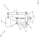
- FIG. 2 shows an adjustment arrangement 20 provided for this purpose, which has a lever 21, among other things.
- a load arm 22 of the lever 21 is coupled in an adjustment connection point 32 to the adjustment vanes of the respective stage, specifically via a connecting rod 25 which converts an offset of the lever 21 into a rotary offset of an adjustment ring 26 .
- the adjusting ring 26 extends around the longitudinal axis of the turbomachine 2 (not shown in detail here) and then transfers the offset to each individual adjusting vane of the respective ring.
- the offset is transmitted to the lever 21 with a coupling rod 27 which is part of a setting device 28 with an actuator 29 .
- the coupling rod 27 couples to a power arm 23 of the lever 21, where it is mounted at an adjustment connection point 33.
- the lever 21 is rotatably mounted about a rotation axis 35 at a pivot point 34 .
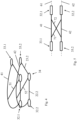
- FIG. 3 shows a lever 21 according to the invention in a top view, namely looking at it axially in relation to the axis of rotation 35 .
- a first power arm 23.1 with a first adjustment connection point 33.1 and a first load arm 22.1 with a first adjustment connection point 32.1 can also be seen.
- the push rod is mounted on the latter, not shown here for the sake of clarity.
- the connection points 32.1, 33.1 are additionally connected to one another via a first strut 41, which extends in an arc around the axis of rotation 35 and runs tangentially into the connection points 32.1, 33.1.
- the arcuate first strut 41 reduces the torques, essentially only normal forces are introduced or passed on. This is an overall advantage with regard to the level of mechanical stress, which is why the lever 21 can be made lighter, cf. the introduction to the description in detail.
- FIG. 4 shows the lever 21 in an oblique view, the basis of figure 3 components described are in a first level 61 (level shown in figure 5 ). Axially offset to this there is a second level 62 (cf. also figure 5 ), in which a second load arm 22.2 with a second adjustment connection point 32.2 and a second force arm 23.2 with a second adjustment connection point 33.2 are arranged. There is also a second arcuate strut 42 which connects the second connection points 32.2, 33.2 to one another. The second arched strut 42 is connected to the pivot point 34 via a second cross strut 52 .
- figure 5 shows the lever 21 in a side view, relative to the axis of rotation 35 looking radially at it.
- the first and the second arcuate strut 41, 42 as well as the respective plane 61, 62 can be seen.
- a first and a second connecting strut 71, 72 (not shown in FIG 4 ) which respectively connect the first and second arcuate struts 41, 42 to each other.
- the connecting struts 71, 72 intersect, axially and also in relation to a rotational position in the middle.
Landscapes
- Engineering & Computer Science (AREA)
- Mechanical Engineering (AREA)
- General Engineering & Computer Science (AREA)
- Structures Of Non-Positive Displacement Pumps (AREA)
Applications Claiming Priority (1)
| Application Number | Priority Date | Filing Date | Title |
|---|---|---|---|
| DE102022103922.6A DE102022103922A1 (de) | 2022-02-18 | 2022-02-18 | Hebel zum verstellen einer verstellschaufel |
Publications (2)
| Publication Number | Publication Date |
|---|---|
| EP4230846A1 true EP4230846A1 (fr) | 2023-08-23 |
| EP4230846B1 EP4230846B1 (fr) | 2026-03-04 |
Family
ID=84982568
Family Applications (1)
| Application Number | Title | Priority Date | Filing Date |
|---|---|---|---|
| EP23152304.4A Active EP4230846B1 (fr) | 2022-02-18 | 2023-01-18 | Levier pour le réglage d'une aube à calage variable |
Country Status (3)
| Country | Link |
|---|---|
| US (1) | US11873722B2 (fr) |
| EP (1) | EP4230846B1 (fr) |
| DE (1) | DE102022103922A1 (fr) |
Cited By (1)
| Publication number | Priority date | Publication date | Assignee | Title |
|---|---|---|---|---|
| DE102023103730A1 (de) * | 2023-02-15 | 2024-08-22 | MTU Aero Engines AG | Verstellsystem für einen Verdichter |
Citations (4)
| Publication number | Priority date | Publication date | Assignee | Title |
|---|---|---|---|---|
| US4295784A (en) * | 1979-09-26 | 1981-10-20 | United Technologies Corporation | Variable stator |
| US5692879A (en) * | 1995-09-27 | 1997-12-02 | Societe Nationale D'etude Et De Construction De Moteurs D'aviation Snecma | Control device for a stage of blades with variable pitch |
| US20060263206A1 (en) * | 2005-05-17 | 2006-11-23 | Snecma | System for controlling stages of variable-pitch stator vanes in a turbomachine |
| US20100080684A1 (en) * | 2008-09-30 | 2010-04-01 | Snecma | System for controlling variable-geometry equipments of a turbomachine, particularly by articulated bellcranks |
Family Cites Families (11)
| Publication number | Priority date | Publication date | Assignee | Title |
|---|---|---|---|---|
| SU775405A1 (ru) | 1979-01-22 | 1980-10-30 | Донецкий Государственный Проектно- Конструкторский И Экспериментальный Институт Комплексной Механизации Шахт "Донгипроуглемаш" | Механизм поворота лопаток направл ющего аппарата турбомашины |
| FR2526491A1 (fr) * | 1982-05-04 | 1983-11-10 | Snecma | Dispositif de reglage de la perte de charge d'au moins un des flux dans un turboreacteur multiflux |
| FR2885968B1 (fr) * | 2005-05-17 | 2007-08-10 | Snecma Moteurs Sa | Systeme de commande d'etages d'aubes de stator a angle de calage variable de turbomachine |
| FR2936559B1 (fr) * | 2008-09-30 | 2013-11-22 | Snecma | Systeme de commande d'equipements a geometrie variable d'une turbomachine faisant partie de corps differents. |
| US9885291B2 (en) * | 2012-08-09 | 2018-02-06 | Snecma | Turbomachine comprising a plurality of fixed radial blades mounted upstream of the fan |
| FR3031772B1 (fr) | 2015-01-19 | 2017-01-13 | Snecma | Systeme de commande d’aubes a calage variable pour une turbomachine |
| FR3033007B1 (fr) * | 2015-02-19 | 2018-07-13 | Safran Aircraft Engines | Dispositif pour le reglage individuel d'une pluralite d'aubes radiales fixes a calage variable dans une turbomachine |
| DE102015109526A1 (de) | 2015-06-15 | 2016-12-15 | Cl Schutzrechtsverwaltungs Gmbh | Verfahren zur generativen Herstellung eines dreidimensionalen Objekts |
| DE102015013182A1 (de) | 2015-10-10 | 2017-04-13 | Diehl Defence Gmbh & Co. Kg | Gehäuse für ein Getriebe und Verwendung eines additiven Fertigungsverfahrens |
| FR3063779B1 (fr) * | 2017-03-07 | 2022-11-04 | Safran Aircraft Engines | Anneau de commande de calage d'un etage d'aube d'un stator |
| FR3076325B1 (fr) | 2017-12-29 | 2019-11-29 | Safran Aircraft Engines | Dispositif de calage variable d'au moins deux rangees annulaires d'aubes fixes pour une turbomachine |
-
2022
- 2022-02-18 DE DE102022103922.6A patent/DE102022103922A1/de active Pending
-
2023
- 2023-01-18 EP EP23152304.4A patent/EP4230846B1/fr active Active
- 2023-02-17 US US18/170,926 patent/US11873722B2/en active Active
Patent Citations (4)
| Publication number | Priority date | Publication date | Assignee | Title |
|---|---|---|---|---|
| US4295784A (en) * | 1979-09-26 | 1981-10-20 | United Technologies Corporation | Variable stator |
| US5692879A (en) * | 1995-09-27 | 1997-12-02 | Societe Nationale D'etude Et De Construction De Moteurs D'aviation Snecma | Control device for a stage of blades with variable pitch |
| US20060263206A1 (en) * | 2005-05-17 | 2006-11-23 | Snecma | System for controlling stages of variable-pitch stator vanes in a turbomachine |
| US20100080684A1 (en) * | 2008-09-30 | 2010-04-01 | Snecma | System for controlling variable-geometry equipments of a turbomachine, particularly by articulated bellcranks |
Cited By (1)
| Publication number | Priority date | Publication date | Assignee | Title |
|---|---|---|---|---|
| DE102023103730A1 (de) * | 2023-02-15 | 2024-08-22 | MTU Aero Engines AG | Verstellsystem für einen Verdichter |
Also Published As
| Publication number | Publication date |
|---|---|
| US11873722B2 (en) | 2024-01-16 |
| US20230265765A1 (en) | 2023-08-24 |
| DE102022103922A1 (de) | 2023-08-24 |
| EP4230846B1 (fr) | 2026-03-04 |
Similar Documents
| Publication | Publication Date | Title |
|---|---|---|
| DE602004006323T2 (de) | Verfahren zur Herstellung einer Turbine mit Turbinenschaufeln unterschiedlicher Resonanzfrequenzen samt einer solchen Turbine | |
| EP3283733B1 (fr) | Dispositif d'actionnement des aubes de guidage variables et turbomachine | |
| EP1201879B1 (fr) | Composant refroidi, noyau de coulage et procédé pour la fabrication dudit composant | |
| EP0596386A1 (fr) | Aube statorique ajustable fabriqué à partir de plastique renforcé par des fibres | |
| EP1447524A2 (fr) | Aube hybride pour turbomachines thermiques | |
| EP3540084A1 (fr) | Procédé de traitement thermique de composants, composant et moteur d'aéronef | |
| EP3450056A1 (fr) | Procédé de fabrication d'un composant d'aluminiure de titane à noyau dur et composant fabriqué selon ledit procédé | |
| DE102018113050B4 (de) | Wastegate-anordnung, ein turbolader zur verwendung der wastegate-anordnung und ein verfahren zum verbinden von teilen einer wastegate-anordnung | |
| WO2016184549A1 (fr) | Compresseur centrifuge, en particulier pour un turbocompresseur à gaz d'échappement d'un moteur à combustion interne | |
| EP4230846B1 (fr) | Levier pour le réglage d'une aube à calage variable | |
| WO2010026005A1 (fr) | Aube de turbine à fréquence propre adaptée au moyen d'un élément rapporté | |
| DE2927654A1 (de) | Kragarmaufbau, insbesondere fuer deckbandabschnitte eines beschaufelten rotors von gasturbinentriebwerken | |
| EP2394028B1 (fr) | Dispositif d'étanchéité sur l'arbre à aubes d'un étage de rotor d'une turbomachine axiale et son utilisation | |
| DE102019117038A1 (de) | Getriebe und Gasturbinentriebwerk | |
| CH714847B1 (de) | Verschalung für einen Turbolader und Turbolader. | |
| EP1836401A1 (fr) | Procede de modification d'un compresseur a plusieurs etages | |
| WO2006048401A1 (fr) | Etage de turbine optimise dans une installation de turbines et procede de conception | |
| DE102018106564A1 (de) | Planetengetriebe, Keilhülse, Gasturbinentriebwerk mit Planetengetriebe und Verfahren zum Herstellen eines Planetengetriebes | |
| EP3176386B1 (fr) | Système de virole interne, virole interne, boîtier intermédiaire et turbomachine associés | |
| WO2022128354A1 (fr) | Composant d'aube, son procédé de production, et turbine à gaz | |
| EP4148236A1 (fr) | Dispositif de réglage pour aubes à calage variable d'une turbomachine | |
| DE102018110632A1 (de) | Verfahren zur Herstellung eines Bauteils | |
| EP4177443A1 (fr) | Levier de réglage pour une aube directrice d'une turbomachine | |
| DE3919606C2 (de) | Axialkraftübertragung vom Verdichteraustrittsleitschaufelkranz auf das Triebwerksaußengehäuse eines Gasturbinentriebwerks unter Minimierung der Schaufeltorsionsbeanspruchung | |
| DE102018126589A1 (de) | Verstellbares Leitschaufelsystem für einen Abgasturbolader |
Legal Events
| Date | Code | Title | Description |
|---|---|---|---|
| PUAI | Public reference made under article 153(3) epc to a published international application that has entered the european phase |
Free format text: ORIGINAL CODE: 0009012 |
|
| STAA | Information on the status of an ep patent application or granted ep patent |
Free format text: STATUS: THE APPLICATION HAS BEEN PUBLISHED |
|
| AK | Designated contracting states |
Kind code of ref document: A1 Designated state(s): AL AT BE BG CH CY CZ DE DK EE ES FI FR GB GR HR HU IE IS IT LI LT LU LV MC ME MK MT NL NO PL PT RO RS SE SI SK SM TR |
|
| STAA | Information on the status of an ep patent application or granted ep patent |
Free format text: STATUS: REQUEST FOR EXAMINATION WAS MADE |
|
| 17P | Request for examination filed |
Effective date: 20240223 |
|
| RBV | Designated contracting states (corrected) |
Designated state(s): AL AT BE BG CH CY CZ DE DK EE ES FI FR GB GR HR HU IE IS IT LI LT LU LV MC ME MK MT NL NO PL PT RO RS SE SI SK SM TR |
|
| GRAP | Despatch of communication of intention to grant a patent |
Free format text: ORIGINAL CODE: EPIDOSNIGR1 |
|
| RIC1 | Information provided on ipc code assigned before grant |
Ipc: F01D 17/16 20060101AFI20250820BHEP Ipc: F04D 29/56 20060101ALI20250820BHEP |
|
| STAA | Information on the status of an ep patent application or granted ep patent |
Free format text: STATUS: GRANT OF PATENT IS INTENDED |
|
| INTG | Intention to grant announced |
Effective date: 20250925 |
|
| GRAS | Grant fee paid |
Free format text: ORIGINAL CODE: EPIDOSNIGR3 |
|
| GRAA | (expected) grant |
Free format text: ORIGINAL CODE: 0009210 |
|
| STAA | Information on the status of an ep patent application or granted ep patent |
Free format text: STATUS: THE PATENT HAS BEEN GRANTED |
|
| AK | Designated contracting states |
Kind code of ref document: B1 Designated state(s): AL AT BE BG CH CY CZ DE DK EE ES FI FR GB GR HR HU IE IS IT LI LT LU LV MC ME MK MT NL NO PL PT RO RS SE SI SK SM TR |
|
| REG | Reference to a national code |
Ref country code: CH Ref legal event code: F10 Free format text: ST27 STATUS EVENT CODE: U-0-0-F10-F00 (AS PROVIDED BY THE NATIONAL OFFICE) Effective date: 20260304 Ref country code: GB Ref legal event code: FG4D Free format text: NOT ENGLISH |
|
| REG | Reference to a national code |
Ref country code: DE Ref legal event code: R096 Ref document number: 502023003208 Country of ref document: DE |
|
| REG | Reference to a national code |
Ref country code: IE Ref legal event code: FG4D Free format text: LANGUAGE OF EP DOCUMENT: GERMAN |