EP4230913A1 - Ensemble combustible de chambre de combustion - Google Patents
Ensemble combustible de chambre de combustion Download PDFInfo
- Publication number
- EP4230913A1 EP4230913A1 EP22197982.6A EP22197982A EP4230913A1 EP 4230913 A1 EP4230913 A1 EP 4230913A1 EP 22197982 A EP22197982 A EP 22197982A EP 4230913 A1 EP4230913 A1 EP 4230913A1
- Authority
- EP
- European Patent Office
- Prior art keywords
- fuel
- central
- wall
- mixing passages
- turbine engine
- Prior art date
- Legal status (The legal status is an assumption and is not a legal conclusion. Google has not performed a legal analysis and makes no representation as to the accuracy of the status listed.)
- Granted
Links
Images



Classifications
-
- F—MECHANICAL ENGINEERING; LIGHTING; HEATING; WEAPONS; BLASTING
- F23—COMBUSTION APPARATUS; COMBUSTION PROCESSES
- F23R—GENERATING COMBUSTION PRODUCTS OF HIGH PRESSURE OR HIGH VELOCITY, e.g. GAS-TURBINE COMBUSTION CHAMBERS
- F23R3/00—Continuous combustion chambers using liquid or gaseous fuel
- F23R3/28—Continuous combustion chambers using liquid or gaseous fuel characterised by the fuel supply
- F23R3/286—Continuous combustion chambers using liquid or gaseous fuel characterised by the fuel supply having fuel-air premixing devices
-
- F—MECHANICAL ENGINEERING; LIGHTING; HEATING; WEAPONS; BLASTING
- F23—COMBUSTION APPARATUS; COMBUSTION PROCESSES
- F23R—GENERATING COMBUSTION PRODUCTS OF HIGH PRESSURE OR HIGH VELOCITY, e.g. GAS-TURBINE COMBUSTION CHAMBERS
- F23R3/00—Continuous combustion chambers using liquid or gaseous fuel
- F23R3/28—Continuous combustion chambers using liquid or gaseous fuel characterised by the fuel supply
- F23R3/36—Supply of different fuels
-
- F—MECHANICAL ENGINEERING; LIGHTING; HEATING; WEAPONS; BLASTING
- F23—COMBUSTION APPARATUS; COMBUSTION PROCESSES
- F23R—GENERATING COMBUSTION PRODUCTS OF HIGH PRESSURE OR HIGH VELOCITY, e.g. GAS-TURBINE COMBUSTION CHAMBERS
- F23R2900/00—Special features of, or arrangements for continuous combustion chambers; Combustion processes therefor
- F23R2900/00002—Gas turbine combustors adapted for fuels having low heating value [LHV]
-
- F—MECHANICAL ENGINEERING; LIGHTING; HEATING; WEAPONS; BLASTING
- F23—COMBUSTION APPARATUS; COMBUSTION PROCESSES
- F23R—GENERATING COMBUSTION PRODUCTS OF HIGH PRESSURE OR HIGH VELOCITY, e.g. GAS-TURBINE COMBUSTION CHAMBERS
- F23R3/00—Continuous combustion chambers using liquid or gaseous fuel
- F23R3/02—Continuous combustion chambers using liquid or gaseous fuel characterised by the air-flow or gas-flow configuration
- F23R3/04—Air inlet arrangements
- F23R3/10—Air inlet arrangements for primary air
- F23R3/12—Air inlet arrangements for primary air inducing a vortex
- F23R3/14—Air inlet arrangements for primary air inducing a vortex by using swirl vanes
-
- F—MECHANICAL ENGINEERING; LIGHTING; HEATING; WEAPONS; BLASTING
- F23—COMBUSTION APPARATUS; COMBUSTION PROCESSES
- F23R—GENERATING COMBUSTION PRODUCTS OF HIGH PRESSURE OR HIGH VELOCITY, e.g. GAS-TURBINE COMBUSTION CHAMBERS
- F23R3/00—Continuous combustion chambers using liquid or gaseous fuel
- F23R3/28—Continuous combustion chambers using liquid or gaseous fuel characterised by the fuel supply
- F23R3/283—Attaching or cooling of fuel injecting means including supports for fuel injectors, stems, or lances
-
- Y—GENERAL TAGGING OF NEW TECHNOLOGICAL DEVELOPMENTS; GENERAL TAGGING OF CROSS-SECTIONAL TECHNOLOGIES SPANNING OVER SEVERAL SECTIONS OF THE IPC; TECHNICAL SUBJECTS COVERED BY FORMER USPC CROSS-REFERENCE ART COLLECTIONS [XRACs] AND DIGESTS
- Y02—TECHNOLOGIES OR APPLICATIONS FOR MITIGATION OR ADAPTATION AGAINST CLIMATE CHANGE
- Y02T—CLIMATE CHANGE MITIGATION TECHNOLOGIES RELATED TO TRANSPORTATION
- Y02T50/00—Aeronautics or air transport
- Y02T50/60—Efficient propulsion technologies, e.g. for aircraft
Definitions
- the present subject matter relates generally to a combustor for a turbine engine having a fuel assembly, and more specifically to a fuel assembly having a fuel-air mixing arrangement.
- Turbine engines are driven by a flow of combustion gases passing through the engine to rotate a multitude of turbine blades, which, in turn, rotate a compressor to provide compressed air to the combustor for combustion.
- a combustor can be provided within the turbine engine and is fluidly coupled with a turbine into which the combustion gases flow.
- hydrocarbon fuels in the combustor of a turbine engine
- air and fuel are fed to a combustion chamber, the air and fuel are mixed, and then the fuel is burned in the presence of the air to produce hot gas.
- the hot gas is then fed to a turbine where it cools and expands to produce power.
- By-products of the fuel combustion typically include environmentally unwanted byproducts, such as nitrogen oxide and nitrogen dioxide (collectively called NO x ), CO, UHC (e.g., methane and volatile organic compounds that contribute to the formation of atmospheric ozone), and other oxides, including oxides of sulfur (e.g., SO 2 and SO 3 ).
- Hydrogen or hydrogen mixed with another element or compound can be used for combustion, however hydrogen or a hydrogen mixed fuel can result in a higher flame temperature than traditional fuels. That is, hydrogen or a hydrogen mixed fuel typically has a wider flammable range and a faster burning velocity than traditional fuels such as petroleum-based fuels, or petroleum and synthetic fuel blends.
- NO x oxides of nitrogen
- UHC unburned hydrocarbons
- CO carbon monoxide
- aspects of the disclosure described herein are directed to a combustor with a fuel nozzle assembly.
- the present disclosure will be described with respect to a turbine engine. It will be understood, however, that aspects of the disclosure described herein are not so limited and that a combustor as described herein can be implemented in engines, including but not limited to turbojet, turboprop, turboshaft, and turbofan engines.
- Aspects of the disclosure discussed herein may have general applicability within non-aircraft engines having a combustor, such as other mobile applications and non-mobile industrial, commercial, and residential applications.
- first, second, and third may be used interchangeably to distinguish one component from another and are not intended to signify location or importance of the individual components.
- forward and aft refer to relative positions within a gas turbine engine or vehicle, and refer to the normal operational attitude of the gas turbine engine or vehicle.
- forward refers to a position closer to an engine inlet and aft refers to a position closer to an engine nozzle or exhaust.
- upstream refers to a direction that is opposite the fluid flow direction
- downstream refers to a direction that is in the same direction as the fluid flow.
- forward means in front of something and "aft” or “rearward” means behind something.
- fore/forward can mean upstream and aft/rearward can mean downstream.
- fluid may be a gas or a liquid.
- fluid communication means that a fluid is capable of making the connection between the areas specified.
- radial refers to a direction away from a common center.
- radial refers to a direction along a ray extending between a center longitudinal axis of the engine and an outer engine circumference.
- Approximating language is applied to modify any quantitative representation that could permissibly vary without resulting in a change in the basic function to which it is related. Accordingly, a value modified by a term or terms, such as “about”, “approximately”, “generally”, and “substantially”, are not to be limited to the precise value specified.
- the approximating language may correspond to the precision of an instrument for measuring the value, or the precision of the methods or machines for constructing or manufacturing the components and/or systems. In at least some instances, the approximating language may correspond to the precision of an instrument for measuring the value, or the precision of the methods or machines for constructing or manufacturing the components and/or systems.
- the approximating language may refer to being within a 1, 2, 4, 5, 10, 15, or 20 percent margin in either individual values, range(s) of values and/or endpoints defining range(s) of values.
- range limitations are combined and interchanged, such ranges are identified and include all the sub-ranges contained therein unless context or language indicates otherwise.
- all ranges disclosed herein are inclusive of the endpoints, and the endpoints are independently combinable with each other.
- FIG. 1 is a schematic view of a turbine engine 10.
- the turbine engine 10 can be used within an aircraft.
- the turbine engine 10 can include, at least, a compressor section 12, a combustion section 14, and a turbine section 16.
- a drive shaft 18 rotationally couples the compressor section 12 and turbine section 16, such that rotation of one affects the rotation of the other, and defines a rotational axis 20 for the turbine engine 10.
- the compressor section 12 can include a low-pressure (LP) compressor 22, and a high-pressure (HP) compressor 24 serially fluidly coupled to one another.
- the turbine section 16 can include an HP turbine 26, and an LP turbine 28 serially fluidly coupled to one another.
- the drive shaft 18 can operatively couple the LP compressor 22, the HP compressor 24, the HP turbine 26 and the LP turbine 28 together.
- the drive shaft 18 can include an LP drive shaft (not illustrated) and an HP drive shaft (not illustrated).
- the LP drive shaft can couple the LP compressor 22 to the LP turbine 28, and the HP drive shaft can couple the HP compressor 24 to the HP turbine 26.
- An LP spool can be defined as the combination of the LP compressor 22, the LP turbine 28, and the LP drive shaft such that the rotation of the LP turbine 28 can apply a driving force to the LP drive shaft, which in turn can rotate the LP compressor 22.
- An HP spool can be defined as the combination of the HP compressor 24, the HP turbine 26, and the HP drive shaft such that the rotation of the HP turbine 26 can apply a driving force to the HP drive shaft which in turn can rotate the HP compressor 24.
- the compressor section 12 can include a plurality of axially spaced stages. Each stage includes a set of circumferentially-spaced rotating blades and a set of circumferentially-spaced stationary vanes.
- the compressor blades for a stage of the compressor section 12 can be mounted to a disk, which is mounted to the drive shaft 18. Each set of blades for a given stage can have its own disk.
- the vanes of the compressor section 12 can be mounted to a casing which can extend circumferentially about the turbine engine 10. It will be appreciated that the representation of the compressor section 12 is merely schematic and that there can be any number of blades, vanes and stages. Further, it is contemplated that there can be any number of other components within the compressor section 12.
- the turbine section 16 can include a plurality of axially spaced stages, with each stage having a set of circumferentially-spaced, rotating blades and a set of circumferentially-spaced, stationary vanes.
- the turbine blades for a stage of the turbine section 16 can be mounted to a disk which is mounted to the drive shaft 18.
- Each set of blades for a given stage can have its own disk.
- the vanes of the turbine section 16 can be mounted to the casing in a circumferential manner. It is noted that there can be any number of blades, vanes and turbine stages as the illustrated turbine section 16 is merely a schematic representation. Further, it is contemplated that there can be any number of other components within the turbine section 16.
- the combustion section 14 can be provided serially between the compressor section 12 and the turbine section 16.
- the combustion section 14 can be fluidly coupled to at least a portion of the compressor section 12 and the turbine section 16 such that the combustion section 14 at least partially fluidly couples the compressor section 12 to the turbine section 16.
- the combustion section 14 can be fluidly coupled to the HP compressor 24 at an upstream end of the combustion section 14 and to the HP turbine 26 at a downstream end of the combustion section 14.
- ambient or atmospheric air is drawn into the compressor section 12 via a fan (not illustrated) upstream of the compressor section 12, where the air is compressed defining a pressurized air.
- the pressurized air can then flow into the combustion section 14 where the pressurized air is mixed with fuel and ignited, thereby generating combustion gases.
- Some work is extracted from these combustion gases by the HP turbine 26, which drives the HP compressor 24.
- the combustion gases are discharged into the LP turbine 28, which extracts additional work to drive the LP compressor 22, and the exhaust gas is ultimately discharged from the turbine engine 10 via an exhaust section (not illustrated) downstream of the turbine section 16.
- the driving of the LP turbine 28 drives the LP spool to rotate the fan (not illustrated) and the LP compressor 22.
- the pressurized airflow and the combustion gases can together define a working airflow that flows through the fan, compressor section 12, combustion section 14, and turbine section 16 of the turbine engine 10.
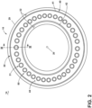
- FIG. 2 depicts a cross-sectional view of the combustion section 14 along line II-II of FIG. 1 .
- the combustion section 14 can include a combustor 30 with an annular arrangement of fuel injectors 31 disposed around the centerline or rotational axis 20 of the turbine engine 10.
- the annular arrangement of fuel injectors 31 can be one or multiple fuel injectors, and one or more of the fuel injectors 31 can have different characteristics.
- multiple fuel injectors 31 can be positioned in a clustered arrangement, such as a single fuel injector or cup having multiple premixer tubes.
- the combustor 30 can have a can, can-annular, or annular arrangement depending on the type of engine in which the combustor 30 is located.
- the combustor 30 can have a combination arrangement located with a casing 29 of the engine 10.
- the combustor 30 can be at least partially defined by a combustor liner 40.
- the combustor liner 40 can include an outer liner 41 and an inner liner 42 concentric with respect to each other and arranged in an annular fashion about the engine centerline or rotational axis 20.
- the combustor liner 40 can have an annular structure about the combustor 30.
- the combustor liner 40 can include multiple segments or portions collectively forming the combustor liner 40.
- a dome assembly 44 together with the combustor liner 40 can at least partially define a combustion chamber 50 arranged annularly about the engine centerline or rotational axis 20.
- a compressed air passageway 32 can be defined at least in part by both the combustor liner 40 and the casing 29.
- FIG. 3 depicts a cross-sectional view taken along line III-III of FIG. 2 illustrating the combustor 30.
- the combustor 30 can include a fuel assembly having a fuel-air mixer 35 configured to provide fuel to the combustor 30.
- the fuel-air mixer 35 can at least partially form the fuel injector 31.
- the fuel-air mixer 35 can include an annular arrangement of fuel nozzles. It should be appreciated that such fuel nozzles can be organized in any suitable arrangement, pattern, grouping, or the like.
- the dome assembly 44 can include a dome wall 46 and a deflector 48.
- the combustor liner 40 and dome assembly 44 can collectively at least partially define the combustion chamber 50 about a longitudinal axis 52.
- the longitudinal axis 52 can extend between a forward direction 52F and an aft direction 52A as shown.
- At least one fuel supply 54 can be fluidly coupled to the combustion chamber 50 to supply fuel to the combustor 30. While only one fuel supply 54 is shown, multiple fuel supplies can be provided, and they can provide the same or different fuels.
- the fuel can include any suitable fuel, including hydrocarbon fuel, hydrogen fuel, or a mixture of differing fuel types, in non-limiting examples.
- the fuel supply 54 can be disposed within the dome assembly 44 to define a fuel outlet 58. It is contemplated that air can also be supplied or provided to the combustion chamber 50 by way of the fuel outlet 58. In this manner, the fuel outlet 58 can provide a fuel-air mixture to the combustion chamber 50.
- a flare cone 56 can be provided downstream of the fuel supply 54 in some examples.
- a swirler 60 can also be provided at the fuel-air mixer 35 to swirl incoming air in proximity to fuel exiting the fuel supply 54 and provide a homogeneous mixture of air and fuel entering the combustor 30. It is also contemplated that the swirler 60 can be integrated into the fuel-air mixer 35.
- a set of dilution holes 62 can be provided in the combustor liner 40 and configured to direct air into the combustion chamber 50 for temperature control, flame shaping, fuel-air mixing, or the like.
- the set of dilution holes 62 is provided in the outer liner 41 and inner liner 42 though this need not be the case. Any number of dilution holes can be provided in the set of dilution holes 62.
- the set of dilution holes 62 can have any suitable patterning or arrangement over the combustor liner 40, including linear rows, irregular groups, variable hole diameters, or the like, or combinations thereof. It is further contemplated that the combustor 30 can be formed without any dilution holes. In some examples, one or more lean premixers can be provided in or adjacent the dome assembly 44.
- the fuel-air mixer 35 can be configured to form multiple, streams of fuel and air into the combustion chamber 50 ( FIG. 3 ).
- the multiple fuel streams can be tailored to the combustion needs.
- the multiple fuel streams can supply different types and/or mixtures of same or different fuel types.
- the fuel-air mixer 35 can include a body 70 having a central axis C as shown. In some examples, the central axis C can be aligned with the longitudinal axis 52 ( FIG. 3 ).
- the body 70 can include a first portion 70A and a second portion 70B.
- the first portion 70A can include or at least partially form the fuel outlet 58 in some examples.
- the body 70 can include an outer wall 71 and a set of inlets 71A in the outer wall 71.
- the set of inlets 71A can have any number, patterning, shape, or arrangement of inlets.
- the set of inlets 71A includes discrete, axially-spaced inlets or apertures configured to direct air into an interior of the body 70 for mixing with fuel therein.
- the set of inlets 71A permit the flow of compressed air, from the compressor section 12 ( FIG. 1 ), into the fuel-air mixer 35.
- FIG. 5 illustrates a front view of the fuel-air mixer 35 with the first portion 70A visible.
- the first portion 70A can include the dome wall 46 though this need not be the case.
- the fuel-air mixer 35 can include one or more outlets forming a set of outlets 78. While six outlets are shown in the set of outlets 78, any number can be provided.
- the set of outlets 78 can collectively form the fuel outlet 58 as shown.
- the set of outlets 78 can have any suitable patterning or arrangement, including linear rows, annular groupings, multiple concentric circles, irregular groupings, or the like, or combinations thereof.
- the set of outlets 78 can be configured to swirl fuel or air exiting the body 70 in some examples.
- the set of outlets 78 can also be configured to emit fuel or air from the body 70 in a jet or otherwise generally straight line in some examples.
- the body 70 can also include multiple internal walls and apertures forming corresponding multiple internal passages configured to direct or mix air and fuel upstream of the fuel outlet 58. Portions of such walls, apertures, and passages are visible through the set of outlets 78 in FIG. 5 . For example, in the view shown, portions of the set of inlets 71A are visible looking through the set of outlets 78.
- FIG. 6 a cross-sectional view of the fuel-air mixer 35 is illustrated along the line VI-VI ( FIG. 5 ).
- the body 70 is illustrated with the first portion 70A and second portion 70B as shown.
- the body 70 can also include an inner wall 72 positioned radially inward of the outer wall 71 with respect to the central axis C.
- An inner set of apertures 72A can be provided in the inner wall 72.
- the body 70 can also include a third wall 73 and a fourth wall 74 having a third set of apertures 73A and a fourth set of apertures 74A, respectively.
- the body 70 can further include a central wall 76 extending along the central axis C as shown.
- the central wall 76 can be in the form of a hollow wall.
- the central wall 76 can be positioned radially inward of the inner wall 72.
- the central wall 76 can also include a central set of apertures 76A as shown.
- outer wall 71, inner wall 72, third wall 73, or fourth wall 74 can extend at least partially along the central axis C, or can extend at least radially with respect to the central axis C, or combinations thereof. In some examples, two or more of the outer wall 71, inner wall 72, third wall 73, or fourth wall 74 can be part of a common wall within the body 70.
- the body 70 can include a set of mixing passages 81, a second set of passages 82, a central fuel passage 85, a central air passage 86, and a set of outlet mixing passages 88.
- the central wall 76 can at least partially form the central fuel passage 85.
- the central wall 76 can separate the central fuel passage 85 and the central air passage 86.
- the central air passage 86 can at least partially surround the central fuel passage 85.
- the set of inlets 71A can be fluidly coupled to the set of mixing passages 81.
- the third set of apertures 73A can fluidly couple the set of mixing passages 81 and the second set of passages 82.
- the inner set of apertures 72A can fluidly couple the central air passage 86 and the set of mixing passages 81.
- the set of outlet mixing passages 88 can be fluidly coupled to at least one of the set of mixing passages 81 or the central air passage 86 by way of the fourth set of apertures 74A.
- the set of outlet mixing passages 88 can be arranged annularly about the central axis C such that, in the illustrated view, portions of multiple passages in the set of outlet mixing passages 88 are shown.
- the central set of apertures 76A can fluidly couple the central fuel passage 85 and the set of outlet mixing passages 88.
- the central set of apertures 76A can form inlets to the set of outlet mixing passages 88 and can have corresponding angles 87 with respect to the central axis C.
- the angle 87 can be between 1-179 degrees, or between 10-150 degrees, or between 20-120 degrees, or the like. Any suitable angle 87 can be provided.
- the central set of apertures 76A can form discrete fuel ports in fluidic connection with the set of outlet mixing passages 88 downstream of the set of mixing passages 81. It is contemplated that the central set of apertures 76A can also include a staggered or varied axial or circumferential position with respect to the central axis C.
- the central set of apertures 76A can be located aft of the inner set of apertures 72A. In this manner, a mixing length can be varied for different fuel streams in a circumferential direction about the fuel-air mixer 35.
- Each outlet in the set of outlets 78 can also define an outlet direction 100 forming an outlet angle 101 with respect to the central axis C.
- the outlet angle 101 can be between -80 degrees and +80 degrees, or between -60 degrees and +60 degrees, or between -20 degrees and +20 degrees, or the like, or combinations thereof. It is further contemplated that the set of outlets 78 can have identical or non-identical outlet angles 101.
- a first fuel flow path 91 can extend sequentially from the second set of passages 82, to the set of mixing passages 81, and to the set of outlet mixing passages 88.
- a second fuel flow path 92 can extend from the central fuel passage 85 to the set of outlet mixing passages 88.
- An inlet flow path 93 can extend through the set of inlets 71A and into the set of mixing passages 81.
- a central air flow path 94 can extend along the central air passage 86 and into the set of mixing passages 81. In this manner, multiple axially-staggered flow paths can be provided in the fuel-air mixer 35.
- air can be supplied into the body 70 along at least one of the inlet flow path 93 or the central air flow path 94, and fuel can be supplied along at least one of the first fuel flow path 91 or the second fuel flow path 92.
- air supplied along the central air passage 86 can be directed or divided into the set of mixing passages 81 and mixed with fuel entering the set of mixing passages 81 from the second set of passages 82.
- Air can also enter the set of mixing passages 81 by way of the set of inlets 71A and mix with fuel or air therein. In this manner, a first fuel-air mixture can be formed within the set of mixing passages 81.
- the first fuel-air mixture can enter the set of outlet mixing passages 88 by way of the fourth set of apertures 74A.
- Additional fuel supplied along the central fuel passage 85 can also be directed into the set of outlet mixing passages 88 by way of the central set of apertures 76A. Such fuel can encounter the first fuel-air mixture supplied from the set of mixing passages 81 and form a second fuel-air mixture or enriched fuel-air mixture within the set of outlet mixing passages 88 exiting the body 70. In this manner, fuel and air can be pre-mixed at multiple axial locations within the body 70 upstream of the set of outlets 78. While described as supplying fuel or air, it will be understood that air, fuel, or mixtures of air and fuel can be supplied by way of any or all of the first fuel flow path 91, second fuel flow path 92, inlet flow path 93, or central air flow path 94.
- Air, fuel, or mixtures thereof can be combined within the set of mixing passages 81 or the set of outlet mixing passages 88. Such mixtures can be directed through the set of outlet mixing passages 88 and provided for combustion within the combustion chamber 50 ( FIG. 3 ) by way of the fuel outlet 58.
- the fuel-air mixer 35 can include 100% hydrogen fuel, a fuel blend with 50-100% hydrogen, a fuel blend with 0-60% hydrogen, a natural gas fuel or fuel blend, a hydrocarbon fuel or fuel blend, a fuel-air mixture with 0-50% fuel or fuel blend and 0-50% air, or the like, or combinations thereof.
- hydrogen fuel can be supplied along the first fuel flow path 91; a fuel blend of 50-100% hydrogen can be supplied along the first fuel flow path 91; a natural gas fuel can be supplied along the second fuel flow path 92; or a fuel blend of 0-60% hydrogen can be supplied along the second fuel flow path 92.
- fuel injection along the central fuel passage 85 can form a pilot during natural gas operation, or for low blends of hydrogen fuel (e.g. 0-50% hydrogen) in some examples.
- the turbine engine 10 can initiate combustion with the fuel-air mixer 35 using a natural gas fuel and later transitioning to other fuels, such as a low-percentage (e.g. 0-50%) hydrogen fuel blend at low power levels and a high-percentage (e.g. 50-100%) hydrogen fuel blend at high power levels.
- the turbine engine 10 ( FIG. 1 ) can initiate combustion with the fuel-air mixer 35 using a natural gas fuel and transition to a 100% hydrogen fuel at max power.
- the turbine engine 10 ( FIG. 1 ) can operate with a high-percentage hydrogen fuel at low power levels and with a natural gas fuel at high power levels.
- FIG. 7 an alternate cross-sectional view of the fuel-air mixer 35 is shown along the line VII-VII ( FIG. 5 ).
- the body 70 having the first portion 70A and second portion 70B is shown.
- the set of outlets 78 can form the fuel outlet 58, as described above.
- the inner wall 72 is shown within the set of mixing passages 81 and having the inner set of apertures 72A.
- An external view of the third wall 73 and third set of apertures 73A is also shown.
- the third wall 73 can be circumferentially offset from either or both of the outer wall 71 or the inner wall 72, with respect to the central axis C, in some examples.
- the inlet flow path 93 is illustrated through the set of inlets 71A.
- the central air flow path 94 is shown extending from the central air passage 86, through the inner set of apertures 72A, and into the set of mixing passages 81.
- the first fuel flow path 91 is shown extending from the second set of passages 82, through the outer set of apertures 73A, and into the set of mixing passages 81.
- the second fuel flow path 92 is shown extending from the central fuel passage 85, through the central set of apertures 76A, and into the set of outlet mixing passages 88.
- fuel, fuel blends, or fuel-air mixtures can be injected along the multiple flow paths at different or staggered axial positions with respect to the central axis C.
- the second fuel flow path 92 can inject fuel downstream of injected fuel from the inner set of apertures 72A.
- Such a staggered arrangement can provide for differences in fuel concentration among the set of outlets 78 which can reduce undesirable combustion dynamics.
- FIG. 8 illustrates a front cross-sectional view of the fuel-air mixer 35 along the line VIII-VIII of FIG. 7 .
- the illustrated view is taken upstream of the set of outlets 78 ( FIG. 7 ).
- portions of the central fuel passage 85, central air passage 86, and the set of outlet mixing passages 88 are shown at one axial position in the body 70 with respect to the central axis C ( FIG. 7 ).
- the set of outlet mixing passages 88 can have constant cross-sectional areas, increasing cross-sectional areas, or decreasing cross-sectional areas, in a direction toward the set of outlets 78 with respect to the central axis C ( FIG. 7 ). It is also contemplated that a geometric profile of the set of outlet mixing passages 88 can be circular, elliptical, or combinations thereof. In some examples, the set of outlet mixing passages 88 can include a circular cross-sectional profile at a first axial position and transition to an elliptical cross-sectional profile at a second axial position with respect to the central axis C ( FIG. 7 ).
- the set of outlet mixing passages 88 can include a first elliptical profile at a first axial position and a second elliptical profile at a second axial position, with the first and second elliptical profiles oriented along different directions.
- the set of outlet mixing passages 88 can be configured to direct outlet streams of fuel, air, or mixtures thereof in multiple directions, including parallel to the central axis C ( FIG. 7 ), circumferentially about the central axis C ( FIG. 7 ), radially with respect to the central axis C ( FIG. 7 ), or combinations thereof.
- Either or both of the set of outlet mixing passages 88 or set of outlets 78 can be configured to provide a swirling fluid flow, a jet, a radial fluid flow, or the like, or combinations thereof, for combustion within the combustion chamber 50 ( FIG. 3 ).
- the fuel-air mixer 35 can have an internal mixer air passage dividing into multiple discrete streams forming multiple discrete outlets (e.g. the set of outlets 78) into the combustion chamber 50 ( FIG. 3 ).
- Fuel can be injected into the multiple discrete streams from multiple discrete apertures (e.g. the inner set of apertures 72A), or from the central fuel passage 85 (e.g. the central set of apertures 76A), or combinations thereof.
- FIG. 9 another fuel-air mixer 135 is shown that can be utilized in the combustor 30 ( FIG. 3 ).
- the fuel-air mixer 135 is similar to the fuel-air mixer 35; therefore, like parts will be identified with like numerals increased by 100, with it being understood that the description of the like parts of the fuel-air mixer 35 applies to the fuel-air mixer 135, except where noted.
- the fuel-air mixer 135 can include a body 170 having a central axis C, a set of inlets 171A, and a set of outlets 178.
- the body 170 can also include a set of mixing passages 181, a second set of passages 182, a central fuel passage 185, a central air passage 186, and a set of outlet mixing passages 188.
- a fourth set of apertures 174A can fluidly couple the set of mixing passages 181 to the set of outlets 178.
- a central set of apertures 176A can fluidly couple the central fuel passage 185 and the set of outlet mixing passages 188.
- the body 170 can define a first length L1, a second length L2, a third length L3, and a fourth length L4.
- the first length L1 can be defined between the set of outlets 178 and the set of inlets 171A.
- the second length L2 can be defined between the set of outlets 178 and the fourth set of apertures 174A.
- the third length L3 can be defined between the set of outlets 178 and the central set of apertures 176A.
- the fourth length L4 can be defined along a portion of the set of outlet mixing passages 188 having at least one flow transition, such as a changing cross-sectional area, shape, or the like.
- any of the first length L1, second length L2, third length L3, or fourth length L4 can be formed with predetermined ratios or relative values with respect to one another.
- the second length L2 can be a predetermined percentage of the first length L1, or the third length L3 can be a predetermined percentage of the first length L1, or the fourth length L4 can be a predetermined percentage of the second length L2.
- the second length L2 can be between 5% and 95% of the first length L1, or between 10% and 90% of the first length L1, or between 20% and 80% of the first length L1, or the like.
- the third length L3 can be between 2% and 100% of the first length L1.
- the fourth length L4 can be between 5% and 100% of the second length L2.
- the body 170 can also define an inner surface 189 and an outer surface 190 along the set of outlet mixing passages 188. Either or both of the inner surface 189 or outer surface 190 can be parallel to the central axis C, or form a positive angle (in some examples, flowing away from the central axis C), or form a negative angle (in some examples, flowing toward the central axis C) with respect to the central axis C. It is also contemplated that a cross-sectional area of an outlet passage in the set of outlet mixing passages 188 can be constant, increasing, or decreasing in a direction toward the set of outlets 178. In this manner, flows can be directed toward the set of outlets 178 with a predetermined velocity and angle.
- the set of outlets 178 can also have an outlet direction 200 forming an outlet angle 201 as shown.
- the outlet angle 201 can be formed with respect to the central axis C, or with respect to a direction along the central fuel passage 185.
- the central fuel passage 185 extends parallel to the central axis C, such that the outlet angle 201 is formed with respect to both the central axis C and central fuel passage 185 though this need not be the case.
- the outlet direction 200 forms a positive outlet angle 201 such that fuel and air diverges radially away from the central axis C upon exiting the body 170. In this manner, a bulk flow direction can be radially outward through the set of outlet mixing passages 188.
- multiple outlets in the set of outlets 178 can have different outlet directions 200, such as alternating outlet directions, multiple groups of identical outlet directions, a randomized arrangement of outlet directions, or the like.
- FIGS. 10 and 11 illustrate a respective front view and a front cross-sectional view of the fuel-air mixer 135 along line XI-XI of FIG. 9 .
- the set of outlets 178 is shown with the set of outlet mixing passages 188.
- the set of outlet mixing passages 188 can have constant cross-sectional areas, increasing cross-sectional areas, or decreasing cross-sectional areas, in a direction toward the set of outlets 178 with respect to the central axis C ( FIG. 9 ). It is also contemplated that a geometric profile of the set of outlet mixing passages 188 can be circular, elliptical, or combinations thereof.
- the set of outlet mixing passages 188 can be configured to direct outlet streams of fuel, air, or mixtures thereof in multiple directions.
- the set of outlet mixing passages 188 can be oriented or extend parallel to the central axis C ( FIG. 9 ), circumferentially about the central axis C ( FIG. 9 ), radially with respect to the central axis C ( FIG. 9 ), or combinations thereof.
- Either or both of the set of outlet mixing passages 188 or set of outlets 178 can be configured to provide a swirling fluid flow, a jet, a radial fluid flow, or the like, or combinations thereof, for combustion within the combustion chamber 50 ( FIG. 3 ).
- FIG. 12 another fuel-air mixer 235 is shown that can be utilized in the combustor 30 ( FIG. 3 ).
- the fuel-air mixer 235 is similar to the fuel-air mixer 35, 135; therefore, like parts will be identified with like numerals further increased by 100, with it being understood that the description of the like parts of the fuel-air mixer 35, 135 applies to the fuel-air mixer 235, except where noted.
- the fuel-air mixer 235 can include a body 270 having a central axis C, a set of inlets 271A, and a set of outlets 278.
- the body 270 can also include a set of mixing passages 281, a second set of passages 282, a central fuel passage 285, a central air passage 286, and a set of outlet mixing passages 288.
- a fourth set of apertures 274A can fluidly couple the set of mixing passages 281 to the set of outlets 278.
- a central set of apertures 276A can fluidly couple the central fuel passage 285 and the set of outlet mixing passages 288.
- the body 270 can define a first length L1, a second length L2, a third length L3, and a fourth length L4.
- the first length L1 can be defined between the set of outlets 278 and the set of inlets 271A.
- the second length L2 can be defined between the set of outlets 278 and the fourth set of apertures 274A.
- the third length L3 can be defined between the set of outlets 278 and the central set of apertures 276A.
- the fourth length L4 can be defined along a portion of the set of outlet mixing passages 288 having at least one flow transition, such as a changing cross-sectional area, shape, or the like.
- any of the first length L1, second length L2, third length L3, or fourth length L4 can be formed with predetermined ratios or relative values with respect to one another.
- the second length L2 can be a predetermined percentage of the first length L1, or the third length L3 can be a predetermined percentage of the first length L1, or the fourth length L4 can be a predetermined percentage of the second length L2.
- the second length L2 can be between 5% and 95% of the first length L1, or between 10% and 90% of the first length L1, or between 20% and 80% of the first length L1, or the like.
- the third length L3 can be between 2% and 100% of the first length L1.
- the fourth length L4 can be between 5% and 100% of the second length L2.
- the body 270 can also define an inner surface 289 and an outer surface 290 along the set of outlet mixing passages 288. Either or both of the inner surface 289 or outer surface 290 can be parallel to the central axis C, form a positive angle with respect to the central axis C, or form a negative angle with respect to the central axis C. In the example shown, the outer surface 290 is parallel to the central axis C and the inner surface 289 forms a negative angle (e.g. converging) with respect to the central axis C.
- a negative angle e.g. converging
- the set of outlets 278 can also have an outlet direction 300 forming an outlet angle 301 as shown.
- the outlet angle 301 can be formed with respect to the central axis C, or with respect to a direction along the central fuel passage 285.
- the outlet direction 300 forms a negative outlet angle 301 such that fuel and air converges toward the central axis C upon exiting the body 270.
- FIGS. 13 and 14 illustrate a respective front view and a front cross-sectional view of the fuel-air mixer 235 along line XIV-XIV of FIG. 12 .
- the set of outlets 278 is shown with the set of outlet mixing passages 288.
- the set of outlet mixing passages 288 can have constant cross-sectional areas, increasing cross-sectional areas, or decreasing cross-sectional areas, in a direction toward the set of outlets 278 with respect to the central axis C ( FIG. 12 ). It is also contemplated that a geometric profile of the set of outlet mixing passages 288 can be circular, elliptical, or combinations thereof.
- the set of outlet mixing passages 288 can be configured to direct outlet streams of fuel, air, or mixtures thereof in multiple directions.
- the set of outlet mixing passages 188 can be oriented or extend parallel to the central axis C ( FIG. 12 ), circumferentially about the central axis C ( FIG. 12 ), radially with respect to the central axis C ( FIG. 12 ), or combinations thereof.
- Either or both of the set of outlet mixing passages 288 or set of outlets 278 can be configured to provide a swirling fluid flow, a jet, a radial fluid flow, or the like, or combinations thereof, for combustion within the combustion chamber 50 ( FIG. 3 ).
- FIG. 15 another fuel-air mixer 335 is shown that can be utilized in the combustor 30 ( FIG. 3 ).
- the fuel-air mixer 335 is similar to the fuel-air mixer 35, 135, 235; therefore, like parts will be identified with like numerals further increased by 100, with it being understood that the description of the like parts of the fuel-air mixer 35, 135, 235 applies to the fuel-air mixer 335, except where noted.
- the fuel-air mixer 335 can include a body 370 having a central axis C, a set of inlets 371A, and a set of outlets 378.
- the body 370 can also include a set of mixing passages 381, a second set of passages 382, a central fuel passage 385, a central air passage 386, and a set of outlet mixing passages 388.
- a fourth set of apertures 374A can fluidly couple the set of mixing passages 381 to the set of outlets 378.
- a central set of apertures 376A can fluidly couple the central fuel passage 385 and the set of outlet mixing passages 388.
- the body 370 can define a first length L1, a second length L2, a third length L3, and a fourth length L4.
- the first length L1 can be defined between the set of outlets 378 and the set of inlets 371A.
- the second length L2 can be defined between the set of outlets 378 and the fourth set of apertures 374A.
- the third length L3 can be defined between the set of outlets 378 and the central set of apertures 376A.
- the fourth length L4 can be defined along a portion of the set of outlet mixing passages 388 having at least one flow transition, such as a changing cross-sectional area, shape, or the like.
- any of the first length L1, second length L2, third length L3, or fourth length L4 can be formed with predetermined ratios or relative values with respect to one another.
- the second length L2 can be a predetermined percentage of the first length L1, or the third length L3 can be a predetermined percentage of the first length L1, or the fourth length L4 can be a predetermined percentage of the second length L2.
- the second length L2 can be between 5% and 95% of the first length L1, or between 10% and 90% of the first length L1, or between 20% and 80% of the first length L1, or the like.
- the third length L3 can be between 2% and 100% of the first length L1.
- the fourth length L4 can be between 5% and 100% of the second length L2.
- the body 370 can also define an inner surface 389 and an outer surface 390 along the set of outlet mixing passages 388. Either or both of the inner surface 389 or outer surface 390 can be parallel to the central axis C, form a positive angle (e.g. diverging) with respect to the central axis C, or form a negative angle (e.g. converging) with respect to the central axis C. In the non-limiting example shown, the outer surface 390 forms a positive angle (e.g. diverging) with respect to the central axis C and the inner surface 389 is parallel to the central axis C.
- the set of outlets 378 can also have an outlet direction 400 forming an outlet angle 401 as shown.
- the outlet angle 401 can be formed with respect to the central axis C, or with respect to a direction along the central fuel passage 385.
- the outlet direction 400 forms a very small, positive outlet angle 401 such that fuel and air is generally parallel to, or diverges slightly from, the central axis C upon exiting the body 370.
- a cross-section along the set of outlet mixing passages 188 can be oriented at least partially along the central axis C and a bulk flow direction can be radially outward from the central axis C.
- FIGS. 16 and 17 illustrate a respective front view and a front cross-sectional view of the fuel-air mixer 335 along line XVII-XVII of FIG. 15 .
- the set of outlets 378 is shown with the set of outlet mixing passages 388.
- the set of outlet mixing passages 388 can have constant cross-sectional areas, increasing cross-sectional areas, or decreasing cross-sectional areas, in a direction toward the set of outlets 378 with respect to the central axis C ( FIG. 15 ). It is also contemplated that a geometric profile of the set of outlet mixing passages 388 can be circular, elliptical, or combinations thereof.
- the set of outlet mixing passages 388 can be configured to direct outlet streams of fuel, air, or mixtures thereof in multiple directions, including parallel to the central axis C ( FIG. 15 ), circumferentially about the central axis C ( FIG. 15 ), radially with respect to the central axis C ( FIG. 15 ), or combinations thereof.
- Either or both of the set of outlet mixing passages 388 or set of outlets 378 can be configured to provide a swirling fluid flow, a jet, a radial fluid flow, or the like, or combinations thereof, for combustion within the combustion chamber 50 ( FIG. 3 ).
- aspects of the disclosure provide for a method of supplying a fuel-air mixture, including an enriched fuel-air mixture, to a turbine engine combustion chamber.
- the method can include supplying air through an air passage, such as the central air passage 86, 186, 286, 386, extending along an axis, such as the central axis (C).
- the method can also include dividing the air from the central air passage 86, 186, 286, 386 among a set of mixing passages, such as the set of mixing passages 81, 181, 281, 381 positioned radially outward of the air passage.
- the method can further include supplying fuel to the set of mixing passages 81, 181, 281, 381 to form a fuel-air mixture within the set of mixing passages 81, 181, 281, 381.
- the method can further include directing the fuel-air mixture to a set of outlet mixing passages 88, 188, 288, 388 extending at least one of axially or radially with respect to the axis (C).
- the method can also include supplying fuel from a second set of passages, such as the second set of passages 82, 182, 282, 382, to the set of mixing passages 81, 181, 281, 381.
- the method can further include supplying additional fuel to at least the set of outlet mixing passages 88, 188, 288, 388, and into the fuel-air mixture therein to form an enriched fuel-air mixture.
- the enriched fuel-air mixture can be supplied to the fuel outlet and into the combustion chamber as described above.
- the above described aspects provide for multiple benefits.
- the internal mixer air passage dividing into multiple discrete streams can provide for improved fuel distribution within the fuel-air mixer, which can increase strain rates and mixing rates. Such an arrangement can provide for a reduction in temperature and a reduction in undesirable combustion byproducts, including NO x .
- Aspects of the present disclosure also provide for a shorter and more compact flame compared to traditional fuel injectors. In one non-limiting example, aspects of the disclosure provide for a flame length less than half the size of a flame in a traditional combustor.
- the multiple discrete streams and staggered axial injection described herein can also provide for improved flow spread within the combustor downstream of the fuel outlet, a shift in flame position away from the combustor liner, and a more uniform fuel-air mixture at the fuel outlet.
- High velocity jets created from discrete outlets can also generate high turbulence within the combustion chamber, providing for better mixing and a more uniform temperature distribution inside the combustor, which can reduce NO x emissions.
- the use of multiple axial lengths for the set of air inlets or set of internal passages can provide for differing mixing lengths within the body of the fuel-air mixer.
- Such an arrangement can provide for selection or tailoring of a fuel-air distribution among the outlets of the fuel-air mixer, driving differences in heat release rates and reducing undesirable combustion dynamics.
- a turbine engine comprising a compressor section, a combustion section, and a turbine section in axial flow arrangement, with the combustion section having a combustor comprising: a combustor liner at least partially defining a combustion chamber, a compressed air passage fluidly coupled to the compressor section and the combustion chamber, at least one fuel supply fluidly coupled to the combustion chamber, and a fuel-air mixer, comprising a body extending along a central axis and having an outer wall, an inner wall located within the body and defining a central air passage fluidly coupled to the compressed air passage, with the inner wall spaced from the outer wall to at least partially define a set of mixing passages between the inner wall and outer wall, with the set of mixing passages spaced radially outward of the central air passage with respect to the central axis, a central wall located radially inward of the inner wall and forming a central fuel passage fluidly coupled to the at least one fuel supply, an inner set of apertures in the inner wall
- the turbine engine of any preceding clause further comprising a set of outlet mixing passages fluidly coupling the set of mixing passages to the combustion chamber, and a central set of apertures in the central wall fluidly coupling the central fuel passage to the set of outlet mixing passages.
- the turbine engine of any preceding clause further comprising a set of inlets in the outer wall of the body and fluidly coupled to the set of mixing passages.
- the turbine engine of any preceding clause further comprising a first fuel flow path extending sequentially from the second set of passages, to the set of mixing passages, and to the set of outlet mixing passages, and a second fuel flow path extending from the central fuel passage to the set of outlet mixing passages.
- the set of inlets comprises axially-spaced inlets with respect to the central axis.
- the turbine engine of any preceding clause further comprising a first length defined between the set of inlets and the set of outlets, a second length defined between the set of outlets and the fourth set of apertures, a third length defined between the set of outlets and the central set of apertures.
- the turbine engine of any preceding clause further defining a fourth length defined along a portion of the set of outlet mixing passages having a flow transition comprising at least one of a changing cross-sectional area or a changing passage shape.
- turbine engine of any preceding clause further comprising an inner surface and an outer surface along an outlet passage in the set of outlet mixing passages.
- a combustor for a turbine engine comprising a combustor liner at least partially defining a combustion chamber, a compressed air passage fluidly coupling a source of compressed air to the combustion chamber, at least one fuel supply fluidly coupled to the combustion chamber, and a fuel-air mixer, comprising: a body extending along a central axis and having an outer wall, an inner wall located within the body and defining a central air passage fluidly coupled to the compressed air passage, with the inner wall spaced from the outer wall to at least partially define a set of mixing passages between the inner wall and outer wall, with the set of mixing passages spaced radially outward of the central air passage with respect to the central axis, a central wall located radially inward of the inner wall and forming a central fuel passage fluidly coupled to the at least one fuel supply, an inner set of apertures in the inner wall fluidly coupling the central air passage to the set of mixing passages, and a central air flow path extending from the central air passage to the set of mixing passages
- combustor of any preceding clause further comprising a set of outlet mixing passages fluidly coupling the set of mixing passages to the combustion chamber, and a central set of apertures in the central wall fluidly coupling the central fuel passage to the set of outlet mixing passages.
- combustor of any preceding clause further comprising a set of inlets in the outer wall of the body and fluidly coupled to the set of mixing passages.
- the combustor of any preceding clause further comprising a first length defined between the set of inlets and the set of outlets, a second length defined between the set of outlets and the fourth set of apertures, a third length defined between the set of outlets and the central set of apertures.
- combustor of any preceding clause further defining a fourth length defined along a portion of the set of outlet mixing passages having a flow transition comprising at least one of a changing cross-sectional area or a changing passage shape.
- a method of supplying a fuel-air mixture to a turbine engine combustion chamber comprising supplying air through an air passage extending along an axis, dividing the air from the air passage among a set of mixing passages positioned radially outward of the air passage, supplying fuel to the set of mixing passages to form a fuel-air mixture within the set of mixing passages, and directing the fuel-air mixture to a set of outlet mixing passages extending at least one of axially or radially with respect to the axis.
- the supplying fuel comprises supplying fuel from a second set of passages to the set of mixing passages.
Landscapes
- Engineering & Computer Science (AREA)
- Chemical & Material Sciences (AREA)
- Combustion & Propulsion (AREA)
- Mechanical Engineering (AREA)
- General Engineering & Computer Science (AREA)
Applications Claiming Priority (2)
| Application Number | Priority Date | Filing Date | Title |
|---|---|---|---|
| US202263311657P | 2022-02-18 | 2022-02-18 | |
| US17/734,469 US12215866B2 (en) | 2022-02-18 | 2022-05-02 | Combustor for a turbine engine having a fuel-air mixer including a set of mixing passages |
Publications (2)
| Publication Number | Publication Date |
|---|---|
| EP4230913A1 true EP4230913A1 (fr) | 2023-08-23 |
| EP4230913B1 EP4230913B1 (fr) | 2024-10-30 |
Family
ID=83506341
Family Applications (1)
| Application Number | Title | Priority Date | Filing Date |
|---|---|---|---|
| EP22197982.6A Active EP4230913B1 (fr) | 2022-02-18 | 2022-09-27 | Moteur à turbine avec mélangeur carburant-air |
Country Status (3)
| Country | Link |
|---|---|
| US (1) | US12215866B2 (fr) |
| EP (1) | EP4230913B1 (fr) |
| CN (1) | CN116624892B (fr) |
Families Citing this family (4)
| Publication number | Priority date | Publication date | Assignee | Title |
|---|---|---|---|---|
| US11692709B2 (en) * | 2021-03-11 | 2023-07-04 | General Electric Company | Gas turbine fuel mixer comprising a plurality of mini tubes for generating a fuel-air mixture |
| US11815269B2 (en) * | 2021-12-29 | 2023-11-14 | General Electric Company | Fuel-air mixing assembly in a turbine engine |
| CN118896307B (zh) * | 2024-08-20 | 2025-09-16 | 厦门大学 | 基于螺旋结构的纯氢燃料的微混旋流喷嘴和燃烧室 |
| US12553611B1 (en) * | 2024-12-06 | 2026-02-17 | Ge Vernova Infrastructure Technology Llc | Hydrogen capable fuel injector assembly |
Citations (5)
| Publication number | Priority date | Publication date | Assignee | Title |
|---|---|---|---|---|
| US20040068973A1 (en) * | 2001-03-09 | 2004-04-15 | Tsutomu Wakabayashi | Burner and gas turbine engine |
| US20180051883A1 (en) * | 2015-04-01 | 2018-02-22 | Siemens Energy, Inc. | Pre-mixing based fuel nozzle for use in a combustion turbine engine |
| US20180128490A1 (en) * | 2016-11-04 | 2018-05-10 | General Electric Company | Multi-point injection mini mixing fuel nozzle assembly |
| US20180128491A1 (en) * | 2016-11-04 | 2018-05-10 | General Electric Company | Multi-point centerbody injector mini mixing fuel nozzle assembly |
| EP4056901A2 (fr) * | 2021-03-11 | 2022-09-14 | General Electric Company | Mélangeur de carburant pur une chambre de combustion de turbine à gaz |
Family Cites Families (200)
| Publication number | Priority date | Publication date | Assignee | Title |
|---|---|---|---|---|
| US2565843A (en) | 1949-06-02 | 1951-08-28 | Elliott Co | Multiple tubular combustion chamber |
| US3917173A (en) | 1972-04-21 | 1975-11-04 | Stal Laval Turbin Ab | Atomizing apparatus for finely distributing a liquid in an air stream |
| US3946552A (en) | 1973-09-10 | 1976-03-30 | General Electric Company | Fuel injection apparatus |
| US3972182A (en) | 1973-09-10 | 1976-08-03 | General Electric Company | Fuel injection apparatus |
| US3980233A (en) | 1974-10-07 | 1976-09-14 | Parker-Hannifin Corporation | Air-atomizing fuel nozzle |
| US4100733A (en) | 1976-10-04 | 1978-07-18 | United Technologies Corporation | Premix combustor |
| GB1581050A (en) | 1976-12-23 | 1980-12-10 | Rolls Royce | Combustion equipment for gas turbine engines |
| US4262482A (en) | 1977-11-17 | 1981-04-21 | Roffe Gerald A | Apparatus for the premixed gas phase combustion of liquid fuels |
| US4215535A (en) | 1978-01-19 | 1980-08-05 | United Technologies Corporation | Method and apparatus for reducing nitrous oxide emissions from combustors |
| US4222232A (en) | 1978-01-19 | 1980-09-16 | United Technologies Corporation | Method and apparatus for reducing nitrous oxide emissions from combustors |
| DE2950535A1 (de) | 1979-11-23 | 1981-06-11 | BBC AG Brown, Boveri & Cie., Baden, Aargau | Brennkammer einer gasturbine mit vormisch/vorverdampf-elementen |
| US4412414A (en) | 1980-09-22 | 1983-11-01 | General Motors Corporation | Heavy fuel combustor |
| DE3361535D1 (en) | 1982-05-28 | 1986-01-30 | Bbc Brown Boveri & Cie | Gas turbine combustion chamber and method of operating it |
| DE3564024D1 (en) | 1984-02-29 | 1988-09-01 | Lucas Ind Plc | Combustion equipment |
| DE3663847D1 (en) | 1985-06-07 | 1989-07-13 | Ruston Gas Turbines Ltd | Combustor for gas turbine engine |
| US5339635A (en) | 1987-09-04 | 1994-08-23 | Hitachi, Ltd. | Gas turbine combustor of the completely premixed combustion type |
| JP2544470B2 (ja) | 1989-02-03 | 1996-10-16 | 株式会社日立製作所 | ガスタ―ビン燃焼器及びその運転方法 |
| US5207064A (en) | 1990-11-21 | 1993-05-04 | General Electric Company | Staged, mixed combustor assembly having low emissions |
| FR2671857B1 (fr) | 1991-01-23 | 1994-12-09 | Snecma | Chambre de combustion, notamment pour turbine a gaz, a paroi deformable. |
| US5235814A (en) | 1991-08-01 | 1993-08-17 | General Electric Company | Flashback resistant fuel staged premixed combustor |
| CA2072275A1 (fr) * | 1991-08-12 | 1993-02-13 | Phillip D. Napoli | Systeme d'alimentation en carburant pour double chambre annulaire de combustion |
| US5263325A (en) | 1991-12-16 | 1993-11-23 | United Technologies Corporation | Low NOx combustion |
| US5307634A (en) | 1992-02-26 | 1994-05-03 | United Technologies Corporation | Premix gas nozzle |
| DE4228816C2 (de) | 1992-08-29 | 1998-08-06 | Mtu Muenchen Gmbh | Brenner für Gasturbinentriebwerke |
| US5251447A (en) | 1992-10-01 | 1993-10-12 | General Electric Company | Air fuel mixer for gas turbine combustor |
| US5265409A (en) | 1992-12-18 | 1993-11-30 | United Technologies Corporation | Uniform cooling film replenishment thermal liner assembly |
| US5404711A (en) * | 1993-06-10 | 1995-04-11 | Solar Turbines Incorporated | Dual fuel injector nozzle for use with a gas turbine engine |
| FR2706534B1 (fr) | 1993-06-10 | 1995-07-21 | Snecma | Diffuseur-séparateur multiflux avec redresseur intégré pour turboréacteur. |
| US5351477A (en) | 1993-12-21 | 1994-10-04 | General Electric Company | Dual fuel mixer for gas turbine combustor |
| US5408830A (en) | 1994-02-10 | 1995-04-25 | General Electric Company | Multi-stage fuel nozzle for reducing combustion instabilities in low NOX gas turbines |
| US5511375A (en) | 1994-09-12 | 1996-04-30 | General Electric Company | Dual fuel mixer for gas turbine combustor |
| DE19510744A1 (de) | 1995-03-24 | 1996-09-26 | Abb Management Ag | Brennkammer mit Zweistufenverbrennung |
| US5619855A (en) | 1995-06-07 | 1997-04-15 | General Electric Company | High inlet mach combustor for gas turbine engine |
| US5791137A (en) | 1995-11-13 | 1998-08-11 | United Technologies Corporation | Radial inflow dual fuel injector |
| US5622054A (en) | 1995-12-22 | 1997-04-22 | General Electric Company | Low NOx lobed mixer fuel injector |
| US5881756A (en) | 1995-12-22 | 1999-03-16 | Institute Of Gas Technology | Process and apparatus for homogeneous mixing of gaseous fluids |
| DE19549143A1 (de) | 1995-12-29 | 1997-07-03 | Abb Research Ltd | Gasturbinenringbrennkammer |
| US5675971A (en) | 1996-01-02 | 1997-10-14 | General Electric Company | Dual fuel mixer for gas turbine combustor |
| GB9607010D0 (en) | 1996-04-03 | 1996-06-05 | Rolls Royce Plc | Gas turbine engine combustion equipment |
| FR2751054B1 (fr) | 1996-07-11 | 1998-09-18 | Snecma | Chambre de combustion anti-nox a injection de carburant de type annulaire |
| US5791562A (en) | 1996-12-20 | 1998-08-11 | United Technologies Corporation | Conical centerbody for a two stream tangential entry nozzle |
| US5816049A (en) | 1997-01-02 | 1998-10-06 | General Electric Company | Dual fuel mixer for gas turbine combustor |
| US5850732A (en) | 1997-05-13 | 1998-12-22 | Capstone Turbine Corporation | Low emissions combustion system for a gas turbine engine |
| JP3448190B2 (ja) | 1997-08-29 | 2003-09-16 | 三菱重工業株式会社 | ガスタービンの燃焼器 |
| US5987889A (en) | 1997-10-09 | 1999-11-23 | United Technologies Corporation | Fuel injector for producing outer shear layer flame for combustion |
| US6176087B1 (en) | 1997-12-15 | 2001-01-23 | United Technologies Corporation | Bluff body premixing fuel injector and method for premixing fuel and air |
| US6038861A (en) | 1998-06-10 | 2000-03-21 | Siemens Westinghouse Power Corporation | Main stage fuel mixer with premixing transition for dry low Nox (DLN) combustors |
| US6286298B1 (en) | 1998-12-18 | 2001-09-11 | General Electric Company | Apparatus and method for rich-quench-lean (RQL) concept in a gas turbine engine combustor having trapped vortex cavity |
| US6295801B1 (en) | 1998-12-18 | 2001-10-02 | General Electric Company | Fuel injector bar for gas turbine engine combustor having trapped vortex cavity |
| EP1070914B1 (fr) | 1999-07-22 | 2003-12-03 | ALSTOM (Switzerland) Ltd | Brûleur à prémélange |
| US6272840B1 (en) | 2000-01-13 | 2001-08-14 | Cfd Research Corporation | Piloted airblast lean direct fuel injector |
| US6609376B2 (en) | 2000-02-14 | 2003-08-26 | Ulstein Turbine As | Device in a burner for gas turbines |
| JP3860952B2 (ja) | 2000-05-19 | 2006-12-20 | 三菱重工業株式会社 | ガスタービン燃焼器 |
| JP2002039533A (ja) | 2000-07-21 | 2002-02-06 | Mitsubishi Heavy Ind Ltd | 燃焼器、ガスタービン及びジェットエンジン |
| US6389815B1 (en) | 2000-09-08 | 2002-05-21 | General Electric Company | Fuel nozzle assembly for reduced exhaust emissions |
| US6367262B1 (en) | 2000-09-29 | 2002-04-09 | General Electric Company | Multiple annular swirler |
| US6442939B1 (en) | 2000-12-22 | 2002-09-03 | Pratt & Whitney Canada Corp. | Diffusion mixer |
| US6438959B1 (en) | 2000-12-28 | 2002-08-27 | General Electric Company | Combustion cap with integral air diffuser and related method |
| US6598584B2 (en) | 2001-02-23 | 2003-07-29 | Clean Air Partners, Inc. | Gas-fueled, compression ignition engine with maximized pilot ignition intensity |
| US6539724B2 (en) | 2001-03-30 | 2003-04-01 | Delavan Inc | Airblast fuel atomization system |
| JP3962554B2 (ja) | 2001-04-19 | 2007-08-22 | 三菱重工業株式会社 | ガスタービン燃焼器及びガスタービン |
| US6564555B2 (en) | 2001-05-24 | 2003-05-20 | Allison Advanced Development Company | Apparatus for forming a combustion mixture in a gas turbine engine |
| JP4610796B2 (ja) | 2001-06-13 | 2011-01-12 | 三菱重工業株式会社 | ガスタービン燃焼器 |
| JP4610800B2 (ja) | 2001-06-29 | 2011-01-12 | 三菱重工業株式会社 | ガスタービン燃焼器 |
| JP3970244B2 (ja) | 2001-07-10 | 2007-09-05 | 三菱重工業株式会社 | 予混合ノズルおよび燃焼器並びにガスタービン |
| US6539721B2 (en) | 2001-07-10 | 2003-04-01 | Pratt & Whitney Canada Corp. | Gas-liquid premixer |
| US6543235B1 (en) | 2001-08-08 | 2003-04-08 | Cfd Research Corporation | Single-circuit fuel injector for gas turbine combustors |
| US6928823B2 (en) | 2001-08-29 | 2005-08-16 | Hitachi, Ltd. | Gas turbine combustor and operating method thereof |
| US6813889B2 (en) | 2001-08-29 | 2004-11-09 | Hitachi, Ltd. | Gas turbine combustor and operating method thereof |
| US6662564B2 (en) | 2001-09-27 | 2003-12-16 | Siemens Westinghouse Power Corporation | Catalytic combustor cooling tube vibration dampening device |
| US20030101729A1 (en) | 2001-12-05 | 2003-06-05 | Honeywell International, Inc. | Retrofittable air assisted fuel injection method to control gaseous and acoustic emissions |
| JP2003194338A (ja) | 2001-12-14 | 2003-07-09 | R Jan Mowill | 可変出口形状を有するガスタービンエンジン用燃料/空気プレミキサ及び出口速度の制御方法 |
| DE10205839B4 (de) | 2002-02-13 | 2011-08-11 | Alstom Technology Ltd. | Vormischbrenner zur Verminderung verbrennungsgetriebener Schwingungen in Verbrennungssystemen |
| GB0219458D0 (en) | 2002-08-21 | 2002-09-25 | Rolls Royce Plc | Fuel injection apparatus |
| US6962055B2 (en) | 2002-09-27 | 2005-11-08 | United Technologies Corporation | Multi-point staging strategy for low emission and stable combustion |
| JP4065947B2 (ja) | 2003-08-05 | 2008-03-26 | 独立行政法人 宇宙航空研究開発機構 | ガスタービン燃焼器用燃料・空気プレミキサー |
| US7284378B2 (en) | 2004-06-04 | 2007-10-23 | General Electric Company | Methods and apparatus for low emission gas turbine energy generation |
| US7017329B2 (en) | 2003-10-10 | 2006-03-28 | United Technologies Corporation | Method and apparatus for mixing substances |
| US7469544B2 (en) | 2003-10-10 | 2008-12-30 | Pratt & Whitney Rocketdyne | Method and apparatus for injecting a fuel into a combustor assembly |
| JP3944609B2 (ja) * | 2003-12-16 | 2007-07-11 | 川崎重工業株式会社 | 燃料ノズル |
| US7013649B2 (en) | 2004-05-25 | 2006-03-21 | General Electric Company | Gas turbine engine combustor mixer |
| WO2005121648A1 (fr) | 2004-06-08 | 2005-12-22 | Alstom Technology Ltd | Bruleur a premelange a alimentation etagee en combustible liquide et procede pour faire fonctionner un bruleur a premelange |
| FR2875854B1 (fr) | 2004-09-29 | 2009-04-24 | Snecma Propulsion Solide Sa | Melangeur pour tuyere a flux separes |
| JP4626251B2 (ja) | 2004-10-06 | 2011-02-02 | 株式会社日立製作所 | 燃焼器及び燃焼器の燃焼方法 |
| EP1817526B1 (fr) | 2004-11-30 | 2019-03-20 | Ansaldo Energia Switzerland AG | Procédé et dispositif de combustion d'hydrogène dans un brûleur a prémelange |
| WO2006069861A1 (fr) | 2004-12-23 | 2006-07-06 | Alstom Technology Ltd | Bruleur de premelange dote d'un parcours de melange |
| WO2006115484A1 (fr) | 2005-04-25 | 2006-11-02 | Williams International Co., L.L.C. | Systeme et procede de refroidissement de moteur a turbine a gaz |
| US7565803B2 (en) | 2005-07-25 | 2009-07-28 | General Electric Company | Swirler arrangement for mixer assembly of a gas turbine engine combustor having shaped passages |
| FR2893390B1 (fr) | 2005-11-15 | 2011-04-01 | Snecma | Fond de chambre de combustion avec ventilation |
| US7762074B2 (en) | 2006-04-04 | 2010-07-27 | Siemens Energy, Inc. | Air flow conditioner for a combustor can of a gas turbine engine |
| EP1867925A1 (fr) | 2006-06-12 | 2007-12-19 | Siemens Aktiengesellschaft | Brûleur |
| US7810333B2 (en) | 2006-10-02 | 2010-10-12 | General Electric Company | Method and apparatus for operating a turbine engine |
| JP2008111651A (ja) | 2006-10-02 | 2008-05-15 | Hitachi Ltd | ガスタービン燃焼器及びガスタービン燃焼器の燃料供給方法 |
| US7908864B2 (en) | 2006-10-06 | 2011-03-22 | General Electric Company | Combustor nozzle for a fuel-flexible combustion system |
| US7770397B2 (en) | 2006-11-03 | 2010-08-10 | Pratt & Whitney Canada Corp. | Combustor dome panel heat shield cooling |
| US7966801B2 (en) | 2006-12-07 | 2011-06-28 | General Electric Company | Apparatus and method for gas turbine active combustion control system |
| GB2444737B (en) | 2006-12-13 | 2009-03-04 | Siemens Ag | Improvements in or relating to burners for a gas turbine engine |
| US7841180B2 (en) | 2006-12-19 | 2010-11-30 | General Electric Company | Method and apparatus for controlling combustor operability |
| EP2225488B1 (fr) | 2007-11-27 | 2013-07-17 | Alstom Technology Ltd | Brûleur à prémélange pour une turbine à gaz |
| JP4906689B2 (ja) | 2007-11-29 | 2012-03-28 | 株式会社日立製作所 | バーナ,燃焼装置及び燃焼装置の改造方法 |
| EP2072899B1 (fr) | 2007-12-19 | 2016-03-30 | Alstom Technology Ltd | Procédé d'injection de carburant |
| US8528337B2 (en) | 2008-01-22 | 2013-09-10 | General Electric Company | Lobe nozzles for fuel and air injection |
| US7926744B2 (en) | 2008-02-21 | 2011-04-19 | Delavan Inc | Radially outward flowing air-blast fuel injector for gas turbine engine |
| EP2107301B1 (fr) | 2008-04-01 | 2016-01-06 | Siemens Aktiengesellschaft | Injection de gaz dans un brûleur |
| EP2107310A1 (fr) | 2008-04-01 | 2009-10-07 | Siemens Aktiengesellschaft | Brûleur |
| EP2107300A1 (fr) | 2008-04-01 | 2009-10-07 | Siemens Aktiengesellschaft | Ensemble de tourbillonnement avec injecteur à gaz |
| US8347630B2 (en) | 2008-09-03 | 2013-01-08 | United Technologies Corp | Air-blast fuel-injector with shield-cone upstream of fuel orifices |
| US8215116B2 (en) | 2008-10-02 | 2012-07-10 | General Electric Company | System and method for air-fuel mixing in gas turbines |
| US8312722B2 (en) | 2008-10-23 | 2012-11-20 | General Electric Company | Flame holding tolerant fuel and air premixer for a gas turbine combustor |
| US8555646B2 (en) | 2009-01-27 | 2013-10-15 | General Electric Company | Annular fuel and air co-flow premixer |
| US8539773B2 (en) | 2009-02-04 | 2013-09-24 | General Electric Company | Premixed direct injection nozzle for highly reactive fuels |
| US8424311B2 (en) | 2009-02-27 | 2013-04-23 | General Electric Company | Premixed direct injection disk |
| US8234871B2 (en) | 2009-03-18 | 2012-08-07 | General Electric Company | Method and apparatus for delivery of a fuel and combustion air mixture to a gas turbine engine using fuel distribution grooves in a manifold disk with discrete air passages |
| CN201408874Y (zh) | 2009-04-21 | 2010-02-17 | 廖述坤 | 易拔插头 |
| US8161751B2 (en) | 2009-04-30 | 2012-04-24 | General Electric Company | High volume fuel nozzles for a turbine engine |
| US8234872B2 (en) | 2009-05-01 | 2012-08-07 | General Electric Company | Turbine air flow conditioner |
| US20110000215A1 (en) | 2009-07-01 | 2011-01-06 | General Electric Company | Combustor Can Flow Conditioner |
| US8607569B2 (en) | 2009-07-01 | 2013-12-17 | General Electric Company | Methods and systems to thermally protect fuel nozzles in combustion systems |
| US20110016866A1 (en) | 2009-07-22 | 2011-01-27 | General Electric Company | Apparatus for fuel injection in a turbine engine |
| US8616002B2 (en) | 2009-07-23 | 2013-12-31 | General Electric Company | Gas turbine premixing systems |
| US8225613B2 (en) | 2009-09-09 | 2012-07-24 | Aurora Flight Sciences Corporation | High altitude combustion system |
| US8276385B2 (en) | 2009-10-08 | 2012-10-02 | General Electric Company | Staged multi-tube premixing injector |
| US8683804B2 (en) | 2009-11-13 | 2014-04-01 | General Electric Company | Premixing apparatus for fuel injection in a turbine engine |
| EP2362148A1 (fr) | 2010-02-23 | 2011-08-31 | Siemens Aktiengesellschaft | Injecteur de carburant et assemblage de tourbillonnement avec mélangeur à lobes |
| US8919673B2 (en) | 2010-04-14 | 2014-12-30 | General Electric Company | Apparatus and method for a fuel nozzle |
| US8590311B2 (en) | 2010-04-28 | 2013-11-26 | General Electric Company | Pocketed air and fuel mixing tube |
| IT1399989B1 (it) | 2010-05-05 | 2013-05-09 | Avio Spa | Gruppo di iniezione per un combustore di una turbina a gas |
| US8943835B2 (en) | 2010-05-10 | 2015-02-03 | General Electric Company | Gas turbine engine combustor with CMC heat shield and methods therefor |
| US8752386B2 (en) | 2010-05-25 | 2014-06-17 | Siemens Energy, Inc. | Air/fuel supply system for use in a gas turbine engine |
| US8671691B2 (en) | 2010-05-26 | 2014-03-18 | General Electric Company | Hybrid prefilming airblast, prevaporizing, lean-premixing dual-fuel nozzle for gas turbine combustor |
| US8850819B2 (en) | 2010-06-25 | 2014-10-07 | United Technologies Corporation | Swirler, fuel and air assembly and combustor |
| US8225591B2 (en) | 2010-08-02 | 2012-07-24 | General Electric Company | Apparatus and filtering systems relating to combustors in combustion turbine engines |
| EP2434221A1 (fr) | 2010-09-22 | 2012-03-28 | Siemens Aktiengesellschaft | Procédé et agencement pour injecter une émulsion dans une flamme |
| EP2434222B1 (fr) | 2010-09-24 | 2019-02-27 | Ansaldo Energia IP UK Limited | Méthode d'opération d'une chambre de combustion |
| EP2436979A1 (fr) | 2010-09-30 | 2012-04-04 | Siemens Aktiengesellschaft | Brûleur pour turbine à gaz |
| US8464537B2 (en) | 2010-10-21 | 2013-06-18 | General Electric Company | Fuel nozzle for combustor |
| US8640974B2 (en) | 2010-10-25 | 2014-02-04 | General Electric Company | System and method for cooling a nozzle |
| US8899048B2 (en) | 2010-11-24 | 2014-12-02 | Delavan Inc. | Low calorific value fuel combustion systems for gas turbine engines |
| US9435537B2 (en) | 2010-11-30 | 2016-09-06 | General Electric Company | System and method for premixer wake and vortex filling for enhanced flame-holding resistance |
| US8322143B2 (en) | 2011-01-18 | 2012-12-04 | General Electric Company | System and method for injecting fuel |
| US8973368B2 (en) | 2011-01-26 | 2015-03-10 | United Technologies Corporation | Mixer assembly for a gas turbine engine |
| GB201107095D0 (en) | 2011-04-28 | 2011-06-08 | Rolls Royce Plc | A head part of an annular combustion chamber |
| US8733106B2 (en) | 2011-05-03 | 2014-05-27 | General Electric Company | Fuel injector and support plate |
| US8938971B2 (en) | 2011-05-11 | 2015-01-27 | Alstom Technology Ltd | Flow straightener and mixer |
| RU2550370C2 (ru) | 2011-05-11 | 2015-05-10 | Альстом Текнолоджи Лтд | Центробежная форсунка с выступающими частями |
| JP5380488B2 (ja) | 2011-05-20 | 2014-01-08 | 株式会社日立製作所 | 燃焼器 |
| US20120308947A1 (en) | 2011-06-06 | 2012-12-06 | General Electric Company | Combustor having a pressure feed |
| US9388985B2 (en) | 2011-07-29 | 2016-07-12 | General Electric Company | Premixing apparatus for gas turbine system |
| US8955327B2 (en) | 2011-08-16 | 2015-02-17 | General Electric Company | Micromixer heat shield |
| US8984887B2 (en) | 2011-09-25 | 2015-03-24 | General Electric Company | Combustor and method for supplying fuel to a combustor |
| US8550809B2 (en) | 2011-10-20 | 2013-10-08 | General Electric Company | Combustor and method for conditioning flow through a combustor |
| US20130101729A1 (en) | 2011-10-21 | 2013-04-25 | John J. Keremes | Real time cap flattening during heat treat |
| US9423137B2 (en) | 2011-12-29 | 2016-08-23 | Rolls-Royce Corporation | Fuel injector with first and second converging fuel-air passages |
| US8438851B1 (en) | 2012-01-03 | 2013-05-14 | General Electric Company | Combustor assembly for use in a turbine engine and methods of assembling same |
| US9182123B2 (en) | 2012-01-05 | 2015-11-10 | General Electric Company | Combustor fuel nozzle and method for supplying fuel to a combustor |
| US9134023B2 (en) | 2012-01-06 | 2015-09-15 | General Electric Company | Combustor and method for distributing fuel in the combustor |
| US9074773B2 (en) | 2012-02-07 | 2015-07-07 | General Electric Company | Combustor assembly with trapped vortex cavity |
| US9303874B2 (en) | 2012-03-19 | 2016-04-05 | General Electric Company | Systems and methods for preventing flashback in a combustor assembly |
| US9212822B2 (en) | 2012-05-30 | 2015-12-15 | General Electric Company | Fuel injection assembly for use in turbine engines and method of assembling same |
| JP5924618B2 (ja) | 2012-06-07 | 2016-05-25 | 川崎重工業株式会社 | 燃料噴射装置 |
| US10253651B2 (en) | 2012-06-14 | 2019-04-09 | United Technologies Corporation | Turbomachine flow control device |
| RU2561956C2 (ru) | 2012-07-09 | 2015-09-10 | Альстом Текнолоджи Лтд | Газотурбинная система сгорания |
| EP2685171B1 (fr) | 2012-07-09 | 2018-03-21 | Ansaldo Energia Switzerland AG | Arrangement de brûleur |
| US8904798B2 (en) | 2012-07-31 | 2014-12-09 | General Electric Company | Combustor |
| US9285121B2 (en) | 2012-08-23 | 2016-03-15 | General Electric Company | Gas turbine cooling circuit including a seal for a perforated plate |
| CN202852884U (zh) | 2012-09-03 | 2013-04-03 | 中国航空动力机械研究所 | 双油路离心雾化喷射装置 |
| US9335050B2 (en) | 2012-09-26 | 2016-05-10 | United Technologies Corporation | Gas turbine engine combustor |
| US9376985B2 (en) | 2012-12-17 | 2016-06-28 | United Technologies Corporation | Ovate swirler assembly for combustors |
| EP2746657A1 (fr) | 2012-12-19 | 2014-06-25 | L'air Liquide, Societe Anonyme Pour L'etude Et L'exploitation Des Procedes Georges Claude | Procédé de combustion d'un combustible et brûleur associé |
| DE102012025375A1 (de) | 2012-12-27 | 2014-07-17 | Rolls-Royce Deutschland Ltd & Co Kg | Verfahren zur Anordnung von Prallkühllöchern und Effusionslöchern in einer Brennkammerwand einer Gasturbine |
| US9416973B2 (en) | 2013-01-07 | 2016-08-16 | General Electric Company | Micromixer assembly for a turbine system and method of distributing an air-fuel mixture to a combustor chamber |
| JP6181997B2 (ja) * | 2013-07-04 | 2017-08-16 | 三菱日立パワーシステムズ株式会社 | ガスタービン燃焼器およびガスタービン燃焼器の燃焼室へ燃料と燃焼用空気を供給する方法 |
| US9476592B2 (en) | 2013-09-19 | 2016-10-25 | General Electric Company | System for injecting fuel in a gas turbine combustor |
| US9482433B2 (en) | 2013-11-11 | 2016-11-01 | Woodward, Inc. | Multi-swirler fuel/air mixer with centralized fuel injection |
| US9435540B2 (en) | 2013-12-11 | 2016-09-06 | General Electric Company | Fuel injector with premix pilot nozzle |
| JP6695801B2 (ja) | 2013-12-23 | 2020-05-20 | ゼネラル・エレクトリック・カンパニイ | 可撓性支持構造体を備えた燃料ノズル |
| US10139111B2 (en) | 2014-03-28 | 2018-11-27 | Siemens Energy, Inc. | Dual outlet nozzle for a secondary fuel stage of a combustor of a gas turbine engine |
| CN105276619B (zh) * | 2014-06-12 | 2018-05-08 | 川崎重工业株式会社 | 适合多种燃料的燃气轮机燃烧器 |
| EP2966350B1 (fr) | 2014-07-10 | 2018-06-13 | Ansaldo Energia Switzerland AG | Dispositif de tourbillonnement axial |
| US20160047316A1 (en) | 2014-08-14 | 2016-02-18 | General Electric Company | Systems and apparatus relating to gas turbine combustors |
| US9964043B2 (en) | 2014-11-11 | 2018-05-08 | General Electric Company | Premixing nozzle with integral liquid evaporator |
| US20160186663A1 (en) * | 2014-12-30 | 2016-06-30 | General Electric Company | Pilot nozzle in gas turbine combustor |
| CN204987087U (zh) | 2015-02-10 | 2016-01-20 | 北京华清燃气轮机与煤气化联合循环工程技术有限公司 | 一种燃气轮机燃烧室直射式双燃料喷嘴 |
| US10101032B2 (en) | 2015-04-01 | 2018-10-16 | General Electric Company | Micromixer system for a turbine system and an associated method thereof |
| US9982892B2 (en) * | 2015-04-16 | 2018-05-29 | General Electric Company | Fuel nozzle assembly including a pilot nozzle |
| US11156117B2 (en) | 2016-04-25 | 2021-10-26 | Raytheon Technologies Corporation | Seal arc segment with sloped circumferential sides |
| US10502425B2 (en) | 2016-06-03 | 2019-12-10 | General Electric Company | Contoured shroud swirling pre-mix fuel injector assembly |
| US10295190B2 (en) * | 2016-11-04 | 2019-05-21 | General Electric Company | Centerbody injector mini mixer fuel nozzle assembly |
| US10690350B2 (en) | 2016-11-28 | 2020-06-23 | General Electric Company | Combustor with axially staged fuel injection |
| US10513987B2 (en) * | 2016-12-30 | 2019-12-24 | General Electric Company | System for dissipating fuel egress in fuel supply conduit assemblies |
| EP3625504B1 (fr) | 2017-05-16 | 2021-11-24 | Siemens Energy Global GmbH & Co. KG | Schéma d'étagement de carburant binaire permettant d'améliorer les émissions de débit dans la combustion d'une turbine à gaz à pré-mélange pauvre |
| US10890329B2 (en) * | 2018-03-01 | 2021-01-12 | General Electric Company | Fuel injector assembly for gas turbine engine |
| CN108844097B (zh) | 2018-03-16 | 2020-04-24 | 南京航空航天大学 | 一种多点贫油直接喷射的低污染燃烧室 |
| US11530650B2 (en) * | 2018-07-13 | 2022-12-20 | Raytheon Technologies Corporation | Gas turbine engine with active variable turbine cooling |
| US10935245B2 (en) * | 2018-11-20 | 2021-03-02 | General Electric Company | Annular concentric fuel nozzle assembly with annular depression and radial inlet ports |
| US11156360B2 (en) * | 2019-02-18 | 2021-10-26 | General Electric Company | Fuel nozzle assembly |
| CN110594786B (zh) | 2019-10-29 | 2021-07-13 | 中国船舶重工集团公司第七0三研究所 | 一种混合分级超低排放燃烧器 |
| US11512853B2 (en) * | 2020-06-30 | 2022-11-29 | General Electric Company | Fuel circuit for a fuel injector |
| EP4426970A2 (fr) * | 2021-11-03 | 2024-09-11 | Power Systems Mfg., LLC | Injecteur pilote multitube ayant un ancrage de flamme pour un moteur à turbine à gaz |
| US12072103B2 (en) * | 2021-12-30 | 2024-08-27 | General Electric Company | Turbine engine fuel premixer |
-
2022
- 2022-05-02 US US17/734,469 patent/US12215866B2/en active Active
- 2022-09-27 EP EP22197982.6A patent/EP4230913B1/fr active Active
- 2022-11-09 CN CN202211399288.5A patent/CN116624892B/zh active Active
Patent Citations (5)
| Publication number | Priority date | Publication date | Assignee | Title |
|---|---|---|---|---|
| US20040068973A1 (en) * | 2001-03-09 | 2004-04-15 | Tsutomu Wakabayashi | Burner and gas turbine engine |
| US20180051883A1 (en) * | 2015-04-01 | 2018-02-22 | Siemens Energy, Inc. | Pre-mixing based fuel nozzle for use in a combustion turbine engine |
| US20180128490A1 (en) * | 2016-11-04 | 2018-05-10 | General Electric Company | Multi-point injection mini mixing fuel nozzle assembly |
| US20180128491A1 (en) * | 2016-11-04 | 2018-05-10 | General Electric Company | Multi-point centerbody injector mini mixing fuel nozzle assembly |
| EP4056901A2 (fr) * | 2021-03-11 | 2022-09-14 | General Electric Company | Mélangeur de carburant pur une chambre de combustion de turbine à gaz |
Also Published As
| Publication number | Publication date |
|---|---|
| CN116624892B (zh) | 2026-01-23 |
| CN116624892A (zh) | 2023-08-22 |
| EP4230913B1 (fr) | 2024-10-30 |
| US20230266009A1 (en) | 2023-08-24 |
| US12215866B2 (en) | 2025-02-04 |
Similar Documents
| Publication | Publication Date | Title |
|---|---|---|
| EP4230913A1 (fr) | Ensemble combustible de chambre de combustion | |
| US12590561B2 (en) | Combustor with lean openings | |
| EP4202305A1 (fr) | Buse de carburant et tourbillonneur | |
| US11649966B1 (en) | Combustor with an ignition tube | |
| EP2241816A2 (fr) | Injecteur de carburant pilote à double orifice | |
| US11725819B2 (en) | Gas turbine fuel nozzle having a fuel passage within a swirler | |
| US12228282B2 (en) | Gas turbine fuel nozzle having an inner air passage and plural outer fuel passages | |
| US11906165B2 (en) | Gas turbine nozzle having an inner air swirler passage and plural exterior fuel passages | |
| US12072103B2 (en) | Turbine engine fuel premixer | |
| US12072099B2 (en) | Gas turbine fuel nozzle having a lip extending from the vanes of a swirler | |
| US11828465B2 (en) | Combustor fuel assembly | |
| CN116498995B (zh) | 涡轮发动机以及用于涡轮发动机的燃烧器 | |
| US12228286B1 (en) | Combustion section with a primary combustion chamber and a secondary combustion chamber | |
| US20230194094A1 (en) | Combustor with a fuel injector | |
| EP4230916A2 (fr) | Chambre de combustion avec un tube d'allumage | |
| US12331932B2 (en) | Turbine engine fuel mixer | |
| US20260009541A1 (en) | Turbine engine with a fuel injector |
Legal Events
| Date | Code | Title | Description |
|---|---|---|---|
| PUAI | Public reference made under article 153(3) epc to a published international application that has entered the european phase |
Free format text: ORIGINAL CODE: 0009012 |
|
| STAA | Information on the status of an ep patent application or granted ep patent |
Free format text: STATUS: THE APPLICATION HAS BEEN PUBLISHED |
|
| AK | Designated contracting states |
Kind code of ref document: A1 Designated state(s): AL AT BE BG CH CY CZ DE DK EE ES FI FR GB GR HR HU IE IS IT LI LT LU LV MC MK MT NL NO PL PT RO RS SE SI SK SM TR |
|
| STAA | Information on the status of an ep patent application or granted ep patent |
Free format text: STATUS: REQUEST FOR EXAMINATION WAS MADE |
|
| 17P | Request for examination filed |
Effective date: 20240213 |
|
| RBV | Designated contracting states (corrected) |
Designated state(s): AL AT BE BG CH CY CZ DE DK EE ES FI FR GB GR HR HU IE IS IT LI LT LU LV MC MK MT NL NO PL PT RO RS SE SI SK SM TR |
|
| GRAP | Despatch of communication of intention to grant a patent |
Free format text: ORIGINAL CODE: EPIDOSNIGR1 |
|
| STAA | Information on the status of an ep patent application or granted ep patent |
Free format text: STATUS: GRANT OF PATENT IS INTENDED |
|
| INTG | Intention to grant announced |
Effective date: 20240506 |
|
| RIC1 | Information provided on ipc code assigned before grant |
Ipc: F23R 3/36 20060101ALI20240422BHEP Ipc: F23R 3/28 20060101AFI20240422BHEP |
|
| GRAS | Grant fee paid |
Free format text: ORIGINAL CODE: EPIDOSNIGR3 |
|
| GRAA | (expected) grant |
Free format text: ORIGINAL CODE: 0009210 |
|
| STAA | Information on the status of an ep patent application or granted ep patent |
Free format text: STATUS: THE PATENT HAS BEEN GRANTED |
|
| P01 | Opt-out of the competence of the unified patent court (upc) registered |
Free format text: CASE NUMBER: APP_51239/2024 Effective date: 20240910 |
|
| AK | Designated contracting states |
Kind code of ref document: B1 Designated state(s): AL AT BE BG CH CY CZ DE DK EE ES FI FR GB GR HR HU IE IS IT LI LT LU LV MC MK MT NL NO PL PT RO RS SE SI SK SM TR |
|
| REG | Reference to a national code |
Ref country code: GB Ref legal event code: FG4D |
|
| REG | Reference to a national code |
Ref country code: CH Ref legal event code: EP |
|
| REG | Reference to a national code |
Ref country code: IE Ref legal event code: FG4D |
|
| REG | Reference to a national code |
Ref country code: DE Ref legal event code: R096 Ref document number: 602022007222 Country of ref document: DE |
|
| REG | Reference to a national code |
Ref country code: LT Ref legal event code: MG9D |
|
| REG | Reference to a national code |
Ref country code: NL Ref legal event code: MP Effective date: 20241030 |
|
| PG25 | Lapsed in a contracting state [announced via postgrant information from national office to epo] |
Ref country code: PT Free format text: LAPSE BECAUSE OF FAILURE TO SUBMIT A TRANSLATION OF THE DESCRIPTION OR TO PAY THE FEE WITHIN THE PRESCRIBED TIME-LIMIT Effective date: 20250228 Ref country code: HR Free format text: LAPSE BECAUSE OF FAILURE TO SUBMIT A TRANSLATION OF THE DESCRIPTION OR TO PAY THE FEE WITHIN THE PRESCRIBED TIME-LIMIT Effective date: 20241030 Ref country code: IS Free format text: LAPSE BECAUSE OF FAILURE TO SUBMIT A TRANSLATION OF THE DESCRIPTION OR TO PAY THE FEE WITHIN THE PRESCRIBED TIME-LIMIT Effective date: 20250228 |
|
| PG25 | Lapsed in a contracting state [announced via postgrant information from national office to epo] |
Ref country code: FI Free format text: LAPSE BECAUSE OF FAILURE TO SUBMIT A TRANSLATION OF THE DESCRIPTION OR TO PAY THE FEE WITHIN THE PRESCRIBED TIME-LIMIT Effective date: 20241030 Ref country code: NL Free format text: LAPSE BECAUSE OF FAILURE TO SUBMIT A TRANSLATION OF THE DESCRIPTION OR TO PAY THE FEE WITHIN THE PRESCRIBED TIME-LIMIT Effective date: 20241030 |
|
| REG | Reference to a national code |
Ref country code: AT Ref legal event code: MK05 Ref document number: 1737192 Country of ref document: AT Kind code of ref document: T Effective date: 20241030 |
|
| PG25 | Lapsed in a contracting state [announced via postgrant information from national office to epo] |
Ref country code: BG Free format text: LAPSE BECAUSE OF FAILURE TO SUBMIT A TRANSLATION OF THE DESCRIPTION OR TO PAY THE FEE WITHIN THE PRESCRIBED TIME-LIMIT Effective date: 20241030 |
|
| PG25 | Lapsed in a contracting state [announced via postgrant information from national office to epo] |
Ref country code: ES Free format text: LAPSE BECAUSE OF FAILURE TO SUBMIT A TRANSLATION OF THE DESCRIPTION OR TO PAY THE FEE WITHIN THE PRESCRIBED TIME-LIMIT Effective date: 20241030 |
|
| PG25 | Lapsed in a contracting state [announced via postgrant information from national office to epo] |
Ref country code: NO Free format text: LAPSE BECAUSE OF FAILURE TO SUBMIT A TRANSLATION OF THE DESCRIPTION OR TO PAY THE FEE WITHIN THE PRESCRIBED TIME-LIMIT Effective date: 20250130 |
|
| PG25 | Lapsed in a contracting state [announced via postgrant information from national office to epo] |
Ref country code: AT Free format text: LAPSE BECAUSE OF FAILURE TO SUBMIT A TRANSLATION OF THE DESCRIPTION OR TO PAY THE FEE WITHIN THE PRESCRIBED TIME-LIMIT Effective date: 20241030 Ref country code: LV Free format text: LAPSE BECAUSE OF FAILURE TO SUBMIT A TRANSLATION OF THE DESCRIPTION OR TO PAY THE FEE WITHIN THE PRESCRIBED TIME-LIMIT Effective date: 20241030 Ref country code: GR Free format text: LAPSE BECAUSE OF FAILURE TO SUBMIT A TRANSLATION OF THE DESCRIPTION OR TO PAY THE FEE WITHIN THE PRESCRIBED TIME-LIMIT Effective date: 20250131 |
|
| PG25 | Lapsed in a contracting state [announced via postgrant information from national office to epo] |
Ref country code: PL Free format text: LAPSE BECAUSE OF FAILURE TO SUBMIT A TRANSLATION OF THE DESCRIPTION OR TO PAY THE FEE WITHIN THE PRESCRIBED TIME-LIMIT Effective date: 20241030 |
|
| PG25 | Lapsed in a contracting state [announced via postgrant information from national office to epo] |
Ref country code: RS Free format text: LAPSE BECAUSE OF FAILURE TO SUBMIT A TRANSLATION OF THE DESCRIPTION OR TO PAY THE FEE WITHIN THE PRESCRIBED TIME-LIMIT Effective date: 20250130 |
|
| PG25 | Lapsed in a contracting state [announced via postgrant information from national office to epo] |
Ref country code: SM Free format text: LAPSE BECAUSE OF FAILURE TO SUBMIT A TRANSLATION OF THE DESCRIPTION OR TO PAY THE FEE WITHIN THE PRESCRIBED TIME-LIMIT Effective date: 20241030 |
|
| PG25 | Lapsed in a contracting state [announced via postgrant information from national office to epo] |
Ref country code: DK Free format text: LAPSE BECAUSE OF FAILURE TO SUBMIT A TRANSLATION OF THE DESCRIPTION OR TO PAY THE FEE WITHIN THE PRESCRIBED TIME-LIMIT Effective date: 20241030 |
|
| PG25 | Lapsed in a contracting state [announced via postgrant information from national office to epo] |
Ref country code: EE Free format text: LAPSE BECAUSE OF FAILURE TO SUBMIT A TRANSLATION OF THE DESCRIPTION OR TO PAY THE FEE WITHIN THE PRESCRIBED TIME-LIMIT Effective date: 20241030 |
|
| PG25 | Lapsed in a contracting state [announced via postgrant information from national office to epo] |
Ref country code: RO Free format text: LAPSE BECAUSE OF FAILURE TO SUBMIT A TRANSLATION OF THE DESCRIPTION OR TO PAY THE FEE WITHIN THE PRESCRIBED TIME-LIMIT Effective date: 20241030 |
|
| PG25 | Lapsed in a contracting state [announced via postgrant information from national office to epo] |
Ref country code: SK Free format text: LAPSE BECAUSE OF FAILURE TO SUBMIT A TRANSLATION OF THE DESCRIPTION OR TO PAY THE FEE WITHIN THE PRESCRIBED TIME-LIMIT Effective date: 20241030 |
|
| PG25 | Lapsed in a contracting state [announced via postgrant information from national office to epo] |
Ref country code: CZ Free format text: LAPSE BECAUSE OF FAILURE TO SUBMIT A TRANSLATION OF THE DESCRIPTION OR TO PAY THE FEE WITHIN THE PRESCRIBED TIME-LIMIT Effective date: 20241030 |
|
| PG25 | Lapsed in a contracting state [announced via postgrant information from national office to epo] |
Ref country code: IT Free format text: LAPSE BECAUSE OF FAILURE TO SUBMIT A TRANSLATION OF THE DESCRIPTION OR TO PAY THE FEE WITHIN THE PRESCRIBED TIME-LIMIT Effective date: 20241030 |
|
| REG | Reference to a national code |
Ref country code: DE Ref legal event code: R097 Ref document number: 602022007222 Country of ref document: DE |
|
| PLBE | No opposition filed within time limit |
Free format text: ORIGINAL CODE: 0009261 |
|
| STAA | Information on the status of an ep patent application or granted ep patent |
Free format text: STATUS: NO OPPOSITION FILED WITHIN TIME LIMIT |
|
| PG25 | Lapsed in a contracting state [announced via postgrant information from national office to epo] |
Ref country code: SE Free format text: LAPSE BECAUSE OF FAILURE TO SUBMIT A TRANSLATION OF THE DESCRIPTION OR TO PAY THE FEE WITHIN THE PRESCRIBED TIME-LIMIT Effective date: 20241030 |
|
| 26N | No opposition filed |
Effective date: 20250731 |
|
| PGFP | Annual fee paid to national office [announced via postgrant information from national office to epo] |
Ref country code: DE Payment date: 20250820 Year of fee payment: 4 |
|
| PGFP | Annual fee paid to national office [announced via postgrant information from national office to epo] |
Ref country code: FR Payment date: 20250821 Year of fee payment: 4 |