EP4230921A1 - Procédé de commande d'une température ambiante, système de chauffage pour commander une température ambiante et dispositif de commande destiné à être utilisé dans un système de chauffage - Google Patents
Procédé de commande d'une température ambiante, système de chauffage pour commander une température ambiante et dispositif de commande destiné à être utilisé dans un système de chauffage Download PDFInfo
- Publication number
- EP4230921A1 EP4230921A1 EP23154637.5A EP23154637A EP4230921A1 EP 4230921 A1 EP4230921 A1 EP 4230921A1 EP 23154637 A EP23154637 A EP 23154637A EP 4230921 A1 EP4230921 A1 EP 4230921A1
- Authority
- EP
- European Patent Office
- Prior art keywords
- room
- temperature
- heat exchange
- determined
- space
- Prior art date
- Legal status (The legal status is an assumption and is not a legal conclusion. Google has not performed a legal analysis and makes no representation as to the accuracy of the status listed.)
- Pending
Links
Images

Classifications
-
- F—MECHANICAL ENGINEERING; LIGHTING; HEATING; WEAPONS; BLASTING
- F24—HEATING; RANGES; VENTILATING
- F24D—DOMESTIC- OR SPACE-HEATING SYSTEMS, e.g. CENTRAL HEATING SYSTEMS; DOMESTIC HOT-WATER SUPPLY SYSTEMS; ELEMENTS OR COMPONENTS THEREFOR
- F24D19/00—Details
- F24D19/10—Arrangement or mounting of control or safety devices
- F24D19/1006—Arrangement or mounting of control or safety devices for water heating systems
- F24D19/1009—Arrangement or mounting of control or safety devices for water heating systems for central heating
- F24D19/1015—Arrangement or mounting of control or safety devices for water heating systems for central heating using a valve or valves
- F24D19/1018—Radiator valves
-
- F—MECHANICAL ENGINEERING; LIGHTING; HEATING; WEAPONS; BLASTING
- F24—HEATING; RANGES; VENTILATING
- F24H—FLUID HEATERS, e.g. WATER OR AIR HEATERS, HAVING HEAT-GENERATING MEANS, e.g. HEAT PUMPS, IN GENERAL
- F24H15/00—Control of fluid heaters
- F24H15/10—Control of fluid heaters characterised by the purpose of the control
- F24H15/174—Supplying heated water with desired temperature or desired range of temperature
- F24H15/175—Supplying heated water with desired temperature or desired range of temperature where the difference between the measured temperature and a set temperature is kept under a predetermined value
-
- F—MECHANICAL ENGINEERING; LIGHTING; HEATING; WEAPONS; BLASTING
- F24—HEATING; RANGES; VENTILATING
- F24H—FLUID HEATERS, e.g. WATER OR AIR HEATERS, HAVING HEAT-GENERATING MEANS, e.g. HEAT PUMPS, IN GENERAL
- F24H15/00—Control of fluid heaters
- F24H15/20—Control of fluid heaters characterised by control inputs
- F24H15/254—Room temperature
-
- F—MECHANICAL ENGINEERING; LIGHTING; HEATING; WEAPONS; BLASTING
- F24—HEATING; RANGES; VENTILATING
- F24H—FLUID HEATERS, e.g. WATER OR AIR HEATERS, HAVING HEAT-GENERATING MEANS, e.g. HEAT PUMPS, IN GENERAL
- F24H15/00—Control of fluid heaters
- F24H15/30—Control of fluid heaters characterised by control outputs; characterised by the components to be controlled
- F24H15/305—Control of valves
- F24H15/31—Control of valves of valves having only one inlet port and one outlet port, e.g. flow rate regulating valves
-
- G—PHYSICS
- G05—CONTROLLING; REGULATING
- G05D—SYSTEMS FOR CONTROLLING OR REGULATING NON-ELECTRIC VARIABLES
- G05D23/00—Control of temperature
- G05D23/19—Control of temperature characterised by the use of electric means
- G05D23/1927—Control of temperature characterised by the use of electric means using a plurality of sensors
- G05D23/193—Control of temperature characterised by the use of electric means using a plurality of sensors sensing the temperaure in different places in thermal relationship with one or more spaces
- G05D23/1932—Control of temperature characterised by the use of electric means using a plurality of sensors sensing the temperaure in different places in thermal relationship with one or more spaces to control the temperature of a plurality of spaces
- G05D23/1934—Control of temperature characterised by the use of electric means using a plurality of sensors sensing the temperaure in different places in thermal relationship with one or more spaces to control the temperature of a plurality of spaces each space being provided with one sensor acting on one or more control means
-
- F—MECHANICAL ENGINEERING; LIGHTING; HEATING; WEAPONS; BLASTING
- F24—HEATING; RANGES; VENTILATING
- F24D—DOMESTIC- OR SPACE-HEATING SYSTEMS, e.g. CENTRAL HEATING SYSTEMS; DOMESTIC HOT-WATER SUPPLY SYSTEMS; ELEMENTS OR COMPONENTS THEREFOR
- F24D2220/00—Components of central heating installations excluding heat sources
- F24D2220/04—Sensors
- F24D2220/042—Temperature sensors
-
- F—MECHANICAL ENGINEERING; LIGHTING; HEATING; WEAPONS; BLASTING
- F24—HEATING; RANGES; VENTILATING
- F24D—DOMESTIC- OR SPACE-HEATING SYSTEMS, e.g. CENTRAL HEATING SYSTEMS; DOMESTIC HOT-WATER SUPPLY SYSTEMS; ELEMENTS OR COMPONENTS THEREFOR
- F24D2220/00—Components of central heating installations excluding heat sources
- F24D2220/20—Heat consumers
- F24D2220/2081—Floor or wall heating panels
Definitions
- the present invention relates to a method for controlling a room temperature, a heating system for controlling a room temperature, and a control device for use in a heating system.
- Said heat exchanger can here z. B. be designed as radiators or underfloor heating and are for the purpose of supplying the energy transport medium via a hydraulic line network with a heat source device usually provided centrally in the building for tempering the energy transport medium, z. B. a heat pump system or an oil / gas / pellet heating system connected.
- the central supply of the energy transport medium results in high demands on the heating system in terms of energy-efficient operation and comfortable control of the room temperatures in each individual room of the large number of rooms to be tempered by the heating system, especially when using a large number of heat exchangers.
- specified target temperatures should be reached as quickly as possible and also kept stable in each individual room, and on the other hand, the heat source device should be operated as energy-efficiently as possible, so that full-load operation of the same is avoided as far as possible.
- a method for controlling a room temperature according to claim 1, a heating system for controlling a room temperature according to claim 14 and a control device for use in a heating system according to claim 15 are provided.
- a method for controlling a room temperature using a heating system based on a hydraulic line network for an energy transport medium assigned first heat exchange device, supplied with the temperature-controlled energy transport medium via the hydraulic line network, which is set up for temperature control of the first space, and a second space assigned to a second space that is separated from the first space and supplied with the temperature-controlled energy transport medium via the hydraulic line network, for temperature control of the second room is furnished.
- the method includes providing a target temperature for the first room and a target temperature for the second room, detecting an actual temperature in the first room and an actual temperature in the second room, determining a first temperature difference between the provided Target temperature for the first room and the detected actual temperature in the first room, determining a second temperature difference between the target temperature provided for the second room and the detected actual temperature in the second room, and controlling a room temperature in the first room by setting an operating parameter of the first heat exchange device that regulates a heat exchange capacity in the first room as a function of the determined first temperature difference and by a Setting an operating parameter of the second heat exchange device, which regulates a heat exchange performance in the second room, as a function of the determined first temperature difference and the determined second temperature difference.
- the room temperature is usually understood to mean the air temperature in the room in question.
- the method according to the invention advantageously enables a comparison of the two rooms with regard to an energy or power requirement in the course of controlling the room temperature, on the basis of which a prioritization of the rooms can be established.
- a higher priority could be assigned to the room with the higher temperature difference between the target and actual temperature, since a higher energy or power requirement is to be expected here to reach the target temperature.
- said prioritization should not be understood as being limited to a direct size comparison of the temperature differences, but can also take place through comparisons on the basis of various reference and/or limit values, as described below.
- the method according to the invention particularly advantageously implements a concept of at least partially diverting an energy flow provided centrally by the heat source device, here in the form of the temperature-controlled energy transport medium, on the basis of said prioritization.
- the flow of energy provided by the heat source device is distributed over the hydraulic line network and is divided among the first and second heat exchange devices according to the operating parameters of the same.
- said energy flow can thus be at least partially diverted from one room to the other by setting the operating parameter that regulates the heat exchange performance on the second heat exchange device.
- the operating parameter of the second heat exchange device that regulates the heat exchange capacity can be set in such a way that a heat exchange capacity in the second room is reduced, which reduces the distribution of the centrally provided Energy flow changes to the effect that now a larger proportion of the energy flow of the first heat exchange device is supplied, so as to promote rapid achievement of the target temperature in the first room.
- the energy flow supplied to the second heat exchange device is reduced in order to increase the energy flow supplied to the first heat immersion device without an operating state of the To change heat source device itself, especially without increasing their operating performance.
- the flow of energy into the second space is at least partially diverted into the first space, which can also be additionally supported by setting the operating parameters on the first heat exchange device itself.
- the heat exchange performance of the second heat exchange device in the second space can be set to zero, so that the energy flow provided is completely supplied to the first heat exchange device.
- the energy flow can be diverted again at least partially from the first room to the second room by adjusting the operating parameters of the second heat exchange device, which not only results in an increase of the second temperature difference is prevented, but also overshooting/undershooting of the room temperature in the first room above/below the desired target temperature is prevented.
- the target temperature in the first room can be reached particularly quickly and conveniently while at the same time energy-efficient operation of the heating system used to control the temperature of a large number of rooms can be achieved by setting the operating parameters of the second heat exchange device as a function of the determined first and second temperature difference is included in controlling the room temperature in the first room.
- the heat source device can be any device that can be used to control the temperature of the energy transport medium, e.g. B. a central oil/gas or pellet heating system or a heat pump system. Tempering can be understood to mean both heating and cooling of the energy transport medium.
- the heat source device can be operated in a heating mode, in the course of which the energy transport medium is heated, so as to supply heat energy to the respective rooms via the heat exchange devices and to increase the room temperature.
- the heat source device is not to be understood as being limited to said heating operation.
- the heat source device can preferably also be operated in a cooling mode (primarily in the form of a heat pump system), in the course of which the energy transport medium is cooled so as to remove thermal energy from the respective rooms via the heat exchange devices and lower the room temperature.
- the method is therefore not limited to the classic case of heating operation, but can be used with regard to a room temperature that is to be lowered, e.g. B. at hot outside temperatures in summer, can also be used in the course of the cooling operation, so that an energy-efficient operation of the heating system is also implemented in this case.
- the heat exchange performance - depending on the operating mode of the heat source device - is a measure of the amount of heat energy supplied to the room (heating operation) or removed from the room (cooling operation) by the respective heat exchange device in the course of a heat exchange between the respective room and to understand the energy transport medium flowing through the respective heat exchange device.
- a positive value of the temperature difference ( ⁇ T) according to Equation 1 means that the target value to be achieved by the respective operation has not yet been reached, whereas a negative value of the temperature difference ( ⁇ T) means that the target value to be achieved by the respective operation has already been reached was exceeded.
- Equation 1 The sign convention according to Equation 1 was selected above only as an example and should not be understood as being limited thereto. Likewise, establishing a sign convention is not a mandatory requirement for the application of the method according to the invention.
- the first and the second heat exchange device are designed as surface heat exchangers, each comprising a heating circuit arranged within a floor and/or within walls and/or within a ceiling of the respective room for the passage of the energy transport medium. At least in the case of the floor, this embodiment is also commonly known as underfloor heating.
- All heat exchange devices of the heating system are preferably designed as surface heat exchangers in the sense of the embodiment described above.
- the operating parameters of the first and second heat exchange devices that regulate the heat exchange performance are flow rates and/or volume flows and/or flow rates of the energy transport medium in the respective heating circuit, in particular it is a degree of opening of one of the heating circuits respective heat exchange device associated control valve.
- control valves here include servomotors, which can be adjusted stepwise or continuously by the control device based on electrical control signals and either on the part of the Can be arranged in advance or on the side of the return of the heating system.
- At least the operating parameter of the second heat exchange device that regulates the heat exchange performance in the second space can be adjusted stepwise with at least one intermediate step or steplessly between a predetermined minimum value and a predetermined maximum value. This preferably also applies to the operating parameter of the first heat exchange device.
- the heat exchange performance in the second room can be adjusted particularly precisely, which means that, compared to a purely binary adjustable operating parameter (e.g. on/off or open/closed), the temperature difference may increase more rapidly when the heat exchange performance is reduced can be avoided.
- a purely binary adjustable operating parameter e.g. on/off or open/closed
- the method according to the invention offers the possibility of also controlling the room temperature in the first room as conveniently as possible by setting the operating parameter of the second heat exchange device, for example in order to prevent overshooting/undershooting of the target temperature (for heating/cooling operation).
- the binary adjustable control valve of the first heat exchange device is fully open, as the room temperature in the first room approaches the target temperature, the flow of energy into the first room can be diverted at least partially into the second room by gradually opening the control valve of the second heat exchange device, whereby said overshoot/undershoot in the first space is eliminated.
- the method further comprises providing a limit value for setting the operating parameter of the second heat exchange device that regulates the heat exchange capacity in the second room, wherein in the course of controlling the room temperature in the first room, the setting of the operating parameter of the second heat exchange device that regulates the heat exchange capacity in the second room takes place in such a way that the heat exchange performance in the second room is reduced if the determined second temperature difference falls below the provided limit value.
- the heat exchange performance of the second heat exchange device is reduced as soon as the room temperature in the second room is within a range predetermined by the limit value around the target temperature of the second room, which means that the energy flow of the heating system can only be at least partially diverted to the first room occurs when the room temperature in the second room is within a predetermined acceptable range of values.
- the limit value provided can be predefined from the outset, or it can be determined in the course of the method as a function of other process variables, in order to provide particularly flexible control even for setpoint temperatures that may change.
- the provision of the limit value for setting the operating parameter of the second heat exchange device that regulates the heat exchange capacity in the second room therefore includes determining the limit value at least as a function of the determined first temperature difference and outputting the determined limit value as a provided limit value.
- the limit value determined corresponds to the first temperature difference, to which a tolerance can optionally be added.
- the energy flow of the heating system is at least partially redirected to the first room as soon as its temperature difference is greater than the temperature difference in the second room, i.e. there is an acute energy requirement (of heating/cooling energy) in the first room
- the determined limit value corresponds to a weighted or an unweighted mean value from the determined first and second temperature differences.
- the method preferably also includes providing a second limit value for setting the operating parameter of the second heat exchange device that regulates the heat exchange capacity in the second room, wherein in the course of controlling the room temperature in the first room, the operating parameter of the second heat exchange device that regulates the heat exchange capacity in the second room is set in such a way that that the heat exchange performance in the second room is increased if the determined first temperature difference falls below the second limit value provided
- Said second limit value is, for example and not by way of limitation, a permanently specified temperature limit which, e.g. B. can be set to 0.5 °C.
- the method further includes specifying a permissible value range for the operating parameter of the second heat exchange device that regulates the heat exchange performance in the second room, which is within a value range between the predetermined maximum value and the predetermined minimum value, wherein in the course of controlling the room temperature in the first room the setting of the operating parameter of the second heat exchange device, which regulates the heat exchange performance in the second room, takes place within the specified permissible value range.
- the determination of the permissible value range for the operating parameter that regulates the heat exchange capacity in the second room includes determining a reference value for setting the operating parameter that regulates the heat exchange capacity in the second room at least as a function of the determined first temperature difference, determining an upper limit of the permissible value range on the basis the determined second temperature difference and the determined reference value, the upper limit in the event that the determined second temperature difference turns out to be less than the determined reference value, is smaller than the predetermined maximum value and the value range between the predetermined minimum value and the determined upper limit is output as the permissible value range for the operating parameter of the second heat exchange device regulating the heat exchange performance in the second room.
- the above-described limitation of the adjustable value range of the operating parameter of the second heat exchange device takes place as a function of the determined temperature differences, in order to enable the room temperature to be controlled as adaptively and flexibly as possible. If the second temperature difference falls below the determined reference value, the maximum value that can be set for the operating parameter on the second heat exchange device in the course of the method is reduced (to said upper limit), as a result of which the maximum heat exchange capacity that can be set for the second heat exchange device is also reduced. Power delta can now be used advantageously on the first heat exchange device, with the second heat exchange device itself still being able to be controlled as part of an individual room control for controlling the room temperature in the second room, but with a reduced value range of the associated operating parameter.
- the reference value can be determined analogously to the limit value described above for setting the operating parameter that regulates the heat exchange capacity in the second room and corresponds, for example, to the first temperature difference or to a mean value of the two temperature differences.
- the upper limit is determined in such a way that the upper limit is reduced relative to the predetermined maximum value as the difference between the determined reference value and the determined second temperature difference increases.
- At least the detection of respective actual temperatures in the first and in the second room, the determination of respective temperature differences between the provided setpoint temperature and the detected actual temperature of the respective first and second room and the control of the room temperature in the first room in predefined repeated at time intervals.
- the heating system additionally comprises N further heat exchange devices supplied with the temperature-controlled energy transport medium via the hydraulic line network, each of which is assigned to one of N further rooms and set up for temperature control of the respective further room, where N ⁇ 1 applies
- the method further comprises providing respective target temperatures for each of the N additional rooms, detecting respective actual temperatures for each of the N additional rooms, determining respective temperature differences between the provided target temperature and the detected actual temperature for each of the N additional rooms Rooms, wherein the control of the room temperature in the first room also includes, for each of the N other rooms, setting an operating parameter of the heat exchange device assigned to the respective room, which regulates a heat exchange performance in the respective additional room, as a function of the determined first and second temperature differences and the determined temperature differences in each of the N includes other rooms.
- the method according to the invention is advantageously expanded for use with a heating system with a large number of heat exchange devices, as a result of which all rooms to be temperature-controlled by the heating system are considered collectively and the energy flow of the heating system is thus redirected particularly efficiently on the basis of said collective consideration takes place in order to be able to operate the heating system in a particularly energy-efficient manner.
- controlling the room temperature in the first room includes setting a temperature of the energy transport medium temperature-controlled by the heat source device for supplying the heat exchange devices and/or setting a volume flow of the energy transport medium temperature-controlled by the heat source device for supplying the heat exchange devices.
- the possible manipulated variables in the course of the method according to the invention for controlling the room temperature are expanded by at least one, in particular by two, further manipulated variables, which can be set in particular as a function of the determined first and second temperature difference.
- the energy flow provided by the heat source device itself can be increased so that, in combination with the already sufficiently described redirection of the energy flow, the desired target temperatures can be reached quickly while at the same time being energy-efficient enable operation of the heating system.
- the method further comprises controlling a room temperature in the second room by setting the operating parameter of the second heat exchange device that regulates the heat exchange capacity in the second room as a function of the determined second temperature difference and by setting the operating parameter of the first heat exchange device that regulates the heat exchange capacity in the first room as a function of the determined first temperature difference and the determined second temperature difference.
- the method according to the invention is therefore not to be understood as being limited to controlling the room temperature in a single room in the building, but can also be advantageously extended to other rooms.
- a heating system for controlling a room temperature, which is based on a hydraulic pipe network for an energy transport medium.
- the heating system comprises at least one heat source device set up for temperature control of the energy transport medium, a first heat exchange device assigned to a first room and supplied with the temperature-controlled energy transport medium via the hydraulic line network, which is set up for temperature control of the first room, and a second room separated from the first room assigned second heat exchange device, which is supplied with the temperature-controlled energy transport medium via the hydraulic line network and is set up for temperature control of the second space, a first temperature sensor arranged in the first space, a second temperature sensor arranged in the second space, and a control device which is connected at least to the first and the second Heat exchange device as well as with the first and the second temperature sensor is coupled.
- the control device is set up to set an operating parameter of the first heat exchange device that regulates heat exchange performance in the first room as a function of a first temperature difference determined by the control device between an actual temperature recorded by the first temperature sensor and one of the set temperature for the first room provided by the control device and an operating parameter of the second heat exchange device that regulates a heat exchange performance in the second room as a function of the determined first temperature difference and as a function of a second temperature difference determined by the control device between an actual temperature detected by the second temperature sensor and a set the target temperature provided by the control device for the second room.
- the heating system according to the second aspect is thus set up to implement the method according to the first aspect and thus offers all the advantages already mentioned in the course of the description of the method, which are not listed again below.
- the target temperatures are preferably provided to the control device by respective target value transmitters of the heating system, which can either be designed as part of the control device and/or can be arranged in the respective room itself.
- residents of the building can set the desired room temperatures directly in the room, e.g. B. via a wall thermostat, or centrally, z. B. via a central user interface of the control device.
- the setpoint adjuster and the temperature sensor of a room are designed together in a uniform thermostat unit.
- the first and second heat exchange devices of the heating system are preferably designed as surface heat exchangers, each of which includes a heating circuit arranged within a floor and/or within walls and/or within a ceiling of the respective room for the passage of the energy transport medium.
- the first and second heat exchange devices designed as surface heat exchangers preferably include a control valve that is assigned to the respective heating circuit and can be adjusted by the control device for adjusting a flow rate and/or a volume flow and/or a flow rate of the energy transport medium in the relevant heating circuit, with the values to be set by the control device
- Operating parameters of the first and second heat exchange devices in the course of controlling the room temperature in the first room are in particular degrees of opening of said control valves
- the heating system preferably additionally comprises N further heat exchange devices which are supplied with the temperature-controlled energy transport medium via the hydraulic line network and are coupled to the control device, each of which is one of N further Rooms are assigned and set up for tempering the respective additional room, as well as N additional temperature sensors coupled to the control device, which are each assigned to one of N additional rooms, where N ⁇ 1 applies.
- the control device is set up to set, in the course of controlling the room temperature in the first room, an operating parameter of the heat exchange device assigned to the respective room, which regulates a heat exchange performance in the respective additional room, as a function of the determined first and second temperature differences and the determined temperature differences in each of the N additional rooms.
- the control device of the heating system is preferably set up, in the course of controlling the room temperature in the first room, to set the operating parameter of the second heat exchange device that regulates the heat exchange capacity in the second room in such a way that the heat exchange capacity in the second room is reduced if the determined second temperature difference is one of the Control device provided limit for setting the heat exchange performance in the second room regulating operating parameters of the second heat exchange device falls below
- control device is also set up to determine said limit value in the course of providing the same at least as a function of the determined first temperature difference, said limit value being in particular the first temperature difference itself or a weighted or an unweighted mean value from the determined first and determined corresponds to the second temperature difference
- the control device of the heating system is preferably set up to define a permissible value range for the operating parameter of the second heat exchange device that regulates the heat exchange performance in the second room, which is within a value range between the predetermined maximum value and the predetermined minimum value, wherein in the course of controlling the room temperature in the first room the setting of the operating parameter of the second heat exchange device, which regulates the heat exchange performance in the second room, is carried out by the control device within the specified permissible value range.
- the control device of the heating system is to determine a reference value for setting the operating parameter that regulates the heat exchange performance in the second room at least as a function of the determined first temperature difference, an upper limit of the permissible value range in the course of determining the permissible value range for the operating parameter that regulates the heat exchange performance in the second room
- the upper limit in the event that the determined second temperature difference turns out to be lower than the determined reference value is smaller than the predetermined maximum value, and the value range between the predetermined minimum value and the determined upper limit as the permissible value range for the operating parameter of the second heat exchange device that regulates the heat exchange performance in the second space.
- control device of the heating system is also coupled to the heat source device and set up, in the course of controlling the room temperature in the first room, to set a temperature and/or a volume flow of the energy transport medium, which is temperature-controlled by the heat source device, for supplying the heat exchange devices, this being in particular dependent on the on the first and second temperature difference present in the control device.
- control device is preferably set up to set the operating parameter of the second heat exchange device that regulates the heat exchange capacity in the second room as a function of the second temperature difference determined by the control device and the operating parameter that regulates the heat exchange capacity in the first room set the first heat exchange device depending on the determined first and the determined second temperature difference.
- a control device for use in a heating system according to the second aspect of the invention.
- FIG. 1 shows a flow chart of an embodiment of the method according to the invention for controlling a room temperature using the heating system based on a hydraulic line network for an energy transport medium with a heat source device, a first heat exchange device assigned to a first room and a second heat exchange device assigned to a second room.
- step S1 a setpoint temperature T setpoint ,1 for the first room and a setpoint temperature T setpoint,2 for the second room are provided.
- step S2 an actual temperature T actual,1 in the first room and an actual temperature T actual,2 in the second room are detected.
- step S3 a first temperature difference ⁇ T 1 is determined between the provided setpoint temperature T setpoint,1 for the first room and the detected actual temperature T actual,1 in the first room.
- step S4 a second temperature difference ⁇ T 2 is determined between the provided setpoint temperature T setpoint,2 for the second room and the detected actual temperature T actual,2 in the second room.
- the temperature differences are determined, for example, in compliance with the sign convention according to Equation 1.
- step S5 a room temperature in the first room is controlled by a combination of step S5.1, setting an operating parameter of the first heat exchange device that regulates a heat exchange performance in the first room as a function of the determined first temperature difference ⁇ T 1 , and step S5.2, one Setting an operating parameter of the second heat exchange device, which regulates a heat exchange performance in the second room, as a function of the ascertained first temperature difference ⁇ T 1 and the ascertained second temperature difference ⁇ T 2 .
- the heat exchange capacity is reduced in step S5.2 by lowering the operating parameter of the second heat exchange device if the second temperature difference ⁇ T 2 from step S4 turns out to be smaller than the first temperature difference ⁇ T 1 from step S3.
- a reduction in the operating parameter corresponds to a reduction in the heat exchange capacity.
- step S5.2 The step of setting the operating parameters of the second heat exchange device according to the method according to the invention is not to be understood as being limited to the exemplary procedure according to step S5.2.
- step S6 there is an optional pause of a predetermined length, before the illustrated sequence is run through again, beginning with step S1.
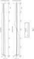
- FIG 2 FIG 2
- FIG 2 and in a diagram for a second room (lower part of 2 ) using a corresponding heating system with two heat exchange devices for the respective temperature control of the first and second room.
- the temperature difference between the target temperature and the actual temperature in the first room is greater than in the second room.
- the operating parameters that regulate the respective heat exchange performance of the heat exchange devices are set, here the relative degrees of opening u 1/2 of the control valves, such that the control valve of the heat exchange device in the first room (first heat exchange device) is maximum is opened, whereas the opening degree u 2 of the control valve of the heat exchange device in the second space (second heat exchange device) is reduced.
- the conceptually described at least partial redirection of an energy flow into the first space takes place in order to cover the higher energy or power requirement there for reaching the setpoint temperature T setpoint,1 .
- the combination of a reduced degree of opening u 2 and an increased degree of opening u 1 leads to an increasing volume flow of the energy transport medium in the first heat exchange device, but also to a reduced volume flow of the energy transport medium in the second heat exchange device, without having to increase the operating performance of the heat source device.
- there is a comparatively sharp increase in the actual temperature T actual,1 in the first room but there is also a drop in the actual temperature T actual,2 in the second room.
- control valves of the first and second heat exchange devices are later throttled at around 1:00 p.m. in the second room and at around 2:00 p.m. in the first room.
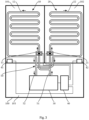
- FIG 3 shows a schematic view of an embodiment of the heating system according to the invention when used in a building 100.
- the building 100 includes three rooms 101, 102, 103, of which a first room 101 and a second room 102 are to be tempered using the heating system.
- the third room 103 serves as a heating room for accommodating one or more components of the heating system.
- the heating system comprises a heat source device designed as a heat pump system 30, a hydraulic line network 50, a first heat exchange device designed as a first surface heat exchanger 10 in the first room 101, a second heat exchange device designed as a second surface heat exchanger 20 in the second room 102, a first temperature sensor 41 arranged in the first room 101 , a second temperature sensor 42 arranged in the second space 102, and a control device 40.
- the heat pump system 30 is set up to control the temperature of an energy transport medium used in the heating system, it being possible for this medium to be heated in the course of a heating operation or to be cooled in the course of a cooling operation.
- the heating system is not limited to said heat pump system 30, but other heat source devices can also be used, such as e.g. B. an oil, gas or pellet heating.
- the heat pump system 30 is usually connected to a geothermal or aerothermal heat source system located outside the building, which is 3 however, is not shown
- the heat pump system 30 is connected to the first surface heat exchanger 10 and the second surface heat exchanger 20 via a hydraulic line network 50 in order to to supply them with the temperature-controlled energy transport medium.
- the respective inlet points of the first and second surface heat exchangers 10, 20 are connected to a central flow 51, via which the energy transport medium, which is tempered by the heat pump system 30, is fed into the hydraulic line network 51.
- the combination of hydraulic line network 50 and surface heat exchangers 10, 20 is usually a closed circuit for the energy transport medium. Consequently, the energy transport medium used for tempering the rooms 101, 102 flows back into the heat pump system via the central return 52, in order to be tempered there again and fed back to the hydraulic line network 50 via the flow 51.
- Flow directions of the energy transport medium are in 3 indicated by the respective arrow directions.
- the first surface heat exchanger 10 comprises a loop-shaped hydraulic heating circuit 12 arranged within the floor of the first room 101 for the passage of the energy transport medium (underfloor heating) and a preferably continuously adjustable control valve 11 upstream of the heating circuit 12 - in relation to the direction of flow
- the energy transport medium flowing through the heating circuit 12 is influenced by a degree of opening of the control valve 11. If the control valve 11 is closed, a volume flow in the heating circuit 12 is equal to zero.
- the position of the control valve 11 is not limited to the supply side, but can also be located on the return side.
- the structure of the second surface heat exchanger 20 in the second space 102 with the associated hydraulic heating circuit 22 and control valve 21 essentially corresponds to that of the first surface heat exchanger 10.
- a volume flow of the energy transport medium provided via the flow 51 is distributed to the two heating circuits 12, 22. If, in the extreme case, one of the two control valves 11 or 21 is closed, the entire energy transport medium flows from the flow 51 directly through the each open heating circuit 22 or 12.
- the temperature sensors 41, 42 are set up to measure a room temperature or an air temperature in the respective room 101, 102 and preferably each include a setpoint generator for entering a desired setpoint temperature in the first and second room 101, 102 by a user.
- the control device 40 is designed to control the heating system and is connected to the heat pump system 30, the control valves 11, 12 and the Temperature sensors 41, 42 coupled In the present case, the coupling is wired, but it can also be based on wireless transmission means.
- control device 40 controlling a room temperature in the first room 101 by means of the heating system, this is set up to determine an opening degree of the control valve 11 of the first surface heat exchanger 10, i.e. an operating parameter of the first surface heat exchanger 10 that regulates a heat exchange capacity in the first room 101, depending on a the first temperature difference determined by the control device 40 between a setpoint temperature provided by the control device 40 for the first room 101 and an actual temperature detected by the first temperature sensor 41 . Furthermore, in the course of controlling the room temperature in the first room 101, the control device is additionally set up to determine an opening degree of the control valve 21 of the second surface heat exchanger 20, i.e.
- an operating parameter of the second surface heat exchanger 20 that regulates a heat exchange capacity in the second room 102, as a function of the determined first temperature difference and in Depending on a second temperature difference determined by the control device 40 between a setpoint temperature provided by the control device 40 for the second room 102 and an actual temperature detected by the second temperature sensor 42 .
- the control device is set up to partially close the control valve 21 of the second surface heat exchanger 20 (i.e. to reduce the degree of opening) in the event that the second temperature difference is less than a provided limit value, which is simplified and not restrictively the determined first temperature difference can act.
- a provided limit value which is simplified and not restrictively the determined first temperature difference can act.
- an energy or power requirement in the first room 101 would have to be classified as greater than in the second room 102, the room temperature of which is already closer to the target temperature.
- the partial closing of the control valve 21 reduces the volume flow in the heating circuit 22 of the second surface heat exchanger 20 and the volume flow in the heating circuit 12 of the first surface heat exchanger 10 increases (e.g.
- the heating system described thus makes it possible to control the room temperature in the first room 101, which not only enables it to be reached as quickly as possible allows the target temperature in the same, but also allows a particularly energy-efficient operation of the heating system.
Landscapes
- Engineering & Computer Science (AREA)
- Physics & Mathematics (AREA)
- Thermal Sciences (AREA)
- Chemical & Material Sciences (AREA)
- Combustion & Propulsion (AREA)
- Mechanical Engineering (AREA)
- General Engineering & Computer Science (AREA)
- Fluid Mechanics (AREA)
- Remote Sensing (AREA)
- General Physics & Mathematics (AREA)
- Automation & Control Theory (AREA)
- Air Conditioning Control Device (AREA)
Applications Claiming Priority (1)
| Application Number | Priority Date | Filing Date | Title |
|---|---|---|---|
| DE102022103778.9A DE102022103778A1 (de) | 2022-02-17 | 2022-02-17 | Verfahren zum Steuern einer Raumtemperatur, Heizungssystem zum Steuern einer Raumtemperatur und Steuervorrichtung zum Einsatz in einem Heizungssystem |
Publications (1)
| Publication Number | Publication Date |
|---|---|
| EP4230921A1 true EP4230921A1 (fr) | 2023-08-23 |
Family
ID=85172587
Family Applications (1)
| Application Number | Title | Priority Date | Filing Date |
|---|---|---|---|
| EP23154637.5A Pending EP4230921A1 (fr) | 2022-02-17 | 2023-02-02 | Procédé de commande d'une température ambiante, système de chauffage pour commander une température ambiante et dispositif de commande destiné à être utilisé dans un système de chauffage |
Country Status (2)
| Country | Link |
|---|---|
| EP (1) | EP4230921A1 (fr) |
| DE (1) | DE102022103778A1 (fr) |
Citations (4)
| Publication number | Priority date | Publication date | Assignee | Title |
|---|---|---|---|---|
| DE4203613A1 (de) * | 1992-02-07 | 1993-08-12 | Sandler Energietechnik | Steuersystem fuer raumheizanlagen |
| WO2009072758A2 (fr) * | 2007-12-04 | 2009-06-11 | Kyungdong Network Co., Ltd. | Procédé de contrôle de système de chauffage |
| EP2175206A2 (fr) | 2008-10-10 | 2010-04-14 | Möhlenhoff Wärmetechnik GmbH | Procédé d'équilibrage des températures de pièces d'un bâtiment |
| EP3470745A1 (fr) * | 2017-10-11 | 2019-04-17 | Jifuh Sheen | Système de commande de chauffage comportant un équilibrage hydraulique |
Family Cites Families (2)
| Publication number | Priority date | Publication date | Assignee | Title |
|---|---|---|---|---|
| DE10312825B4 (de) | 2003-03-22 | 2006-01-12 | Danfoss A/S | Verfahren zum Einstellen mehrerer parallel geschalteter Wärmetauscher |
| DE102017101047B4 (de) | 2017-01-20 | 2023-01-12 | Insta Gmbh | Verfahren zum Betreiben einer Heizungsanlage eines Gebäudes sowie gebäudetechnische Heizungsanlage |
-
2022
- 2022-02-17 DE DE102022103778.9A patent/DE102022103778A1/de active Pending
-
2023
- 2023-02-02 EP EP23154637.5A patent/EP4230921A1/fr active Pending
Patent Citations (4)
| Publication number | Priority date | Publication date | Assignee | Title |
|---|---|---|---|---|
| DE4203613A1 (de) * | 1992-02-07 | 1993-08-12 | Sandler Energietechnik | Steuersystem fuer raumheizanlagen |
| WO2009072758A2 (fr) * | 2007-12-04 | 2009-06-11 | Kyungdong Network Co., Ltd. | Procédé de contrôle de système de chauffage |
| EP2175206A2 (fr) | 2008-10-10 | 2010-04-14 | Möhlenhoff Wärmetechnik GmbH | Procédé d'équilibrage des températures de pièces d'un bâtiment |
| EP3470745A1 (fr) * | 2017-10-11 | 2019-04-17 | Jifuh Sheen | Système de commande de chauffage comportant un équilibrage hydraulique |
Also Published As
| Publication number | Publication date |
|---|---|
| DE102022103778A1 (de) | 2023-08-17 |
Similar Documents
| Publication | Publication Date | Title |
|---|---|---|
| EP2960587B1 (fr) | Procédé de limitation du débit d'alimentation dans un système de transmission de chaleur | |
| EP1606556B1 (fr) | Procede pour assurer le reglage de plusieurs echangeurs de chaleur couples en parallele | |
| EP2354682B1 (fr) | Procédé et dispositif destinés au réglage d'un dispositif de thermorégulation | |
| DE2714511C2 (de) | Vorrichtung zur Regelung der Vorlauftemperatur in einer Sammelheizungsanlage | |
| EP3593055B1 (fr) | Procédé pour faire fonctionner une installation de chauffage | |
| EP3665542B1 (fr) | Dispositif de réglage autorégulé pour une vanne de régulation de fluide, système de thermorégulation et un système de distribution comprenant celui-ci, ainsi que procédé associé | |
| DE102009004319A1 (de) | Verfahren, Computerprogramm und Regelgerät für einen temperaturbasierten hydraulischen Abgleich | |
| EP1936288B1 (fr) | Procédé et système destinés à la détection d'un équilibrage hydraulique d'une installation de chauffage | |
| EP1645928B1 (fr) | Procédé de détermination de l'état d'alimentation d'une surface chauffante et régulateur d'état d'alimentation | |
| DE102012020750A1 (de) | Verfahren zur Optimierung eines thermischen und eines hydraulischen Abgleichs in einer Temperieranlage | |
| DE102010053211A1 (de) | Verfahren zum Betreiben eines Heizungssystems | |
| EP2636959B1 (fr) | Réglage de radiateur | |
| DE2308578C3 (de) | Zentralheizungs- und -kühlanlage | |
| EP2095028B1 (fr) | Système de régulation thermostatique et procédé pour le fonctionnement des modes de chauffage et de refroidissement d'un tel système de régulation thermostatique | |
| EP3473939B1 (fr) | Procédé de fonctionnement d'une installation de chauffage et installation de chauffage | |
| EP3647899A1 (fr) | Procédé de fonctionnement d'une soupape, unité de commande électronique associée et entraînement de soupape | |
| EP1191287A2 (fr) | Système de tuyauterie pour l'échange d'énergie thermique | |
| WO2023186783A1 (fr) | Procédé de commande de système de chauffage, système de chauffage et dispositif de commande | |
| DE10144595B4 (de) | Zentralheizungsanlage | |
| EP4230921A1 (fr) | Procédé de commande d'une température ambiante, système de chauffage pour commander une température ambiante et dispositif de commande destiné à être utilisé dans un système de chauffage | |
| EP3168540A1 (fr) | Procédé d'exécution d'un équilibrage hydraulique automatisé, soupape et installation de chauffage associées | |
| DE102010055080A1 (de) | Verfahren zur Optimierung der Vorlaufsolltemperatur eines Heizfluids und Heizsystem zur Beheizung von zumindest zwei separaten Räumen | |
| DE102015113340A1 (de) | Heizungsanlage und Verfahren zum Betreiben einer Heizungsanlage | |
| DE102024110398A1 (de) | Verfahren zur Steuerung einer Heizungsanlage und Heizungsanlage zur Durchführung des Verfahrens | |
| DE102023103643A1 (de) | Vorrichtung für ein Heizsystem sowie Heizsystem und Verfahren zu dessen Betrieb |
Legal Events
| Date | Code | Title | Description |
|---|---|---|---|
| PUAI | Public reference made under article 153(3) epc to a published international application that has entered the european phase |
Free format text: ORIGINAL CODE: 0009012 |
|
| STAA | Information on the status of an ep patent application or granted ep patent |
Free format text: STATUS: THE APPLICATION HAS BEEN PUBLISHED |
|
| AK | Designated contracting states |
Kind code of ref document: A1 Designated state(s): AL AT BE BG CH CY CZ DE DK EE ES FI FR GB GR HR HU IE IS IT LI LT LU LV MC ME MK MT NL NO PL PT RO RS SE SI SK SM TR |
|
| STAA | Information on the status of an ep patent application or granted ep patent |
Free format text: STATUS: REQUEST FOR EXAMINATION WAS MADE |
|
| 17P | Request for examination filed |
Effective date: 20240223 |
|
| RBV | Designated contracting states (corrected) |
Designated state(s): AL AT BE BG CH CY CZ DE DK EE ES FI FR GB GR HR HU IE IS IT LI LT LU LV MC ME MK MT NL NO PL PT RO RS SE SI SK SM TR |
|
| RAP1 | Party data changed (applicant data changed or rights of an application transferred) |
Owner name: VIESSMANN HOLDING INTERNATIONAL GMBH |
|
| STAA | Information on the status of an ep patent application or granted ep patent |
Free format text: STATUS: EXAMINATION IS IN PROGRESS |
|
| 17Q | First examination report despatched |
Effective date: 20260316 |