EP2960587B1 - Procédé de limitation du débit d'alimentation dans un système de transmission de chaleur - Google Patents
Procédé de limitation du débit d'alimentation dans un système de transmission de chaleur Download PDFInfo
- Publication number
- EP2960587B1 EP2960587B1 EP14173714.8A EP14173714A EP2960587B1 EP 2960587 B1 EP2960587 B1 EP 2960587B1 EP 14173714 A EP14173714 A EP 14173714A EP 2960587 B1 EP2960587 B1 EP 2960587B1
- Authority
- EP
- European Patent Office
- Prior art keywords
- load
- supply
- temperature
- flow
- limiting
- Prior art date
- Legal status (The legal status is an assumption and is not a legal conclusion. Google has not performed a legal analysis and makes no representation as to the accuracy of the status listed.)
- Active
Links
Images



Classifications
-
- F—MECHANICAL ENGINEERING; LIGHTING; HEATING; WEAPONS; BLASTING
- F24—HEATING; RANGES; VENTILATING
- F24D—DOMESTIC- OR SPACE-HEATING SYSTEMS, e.g. CENTRAL HEATING SYSTEMS; DOMESTIC HOT-WATER SUPPLY SYSTEMS; ELEMENTS OR COMPONENTS THEREFOR
- F24D19/00—Details
- F24D19/10—Arrangement or mounting of control or safety devices
- F24D19/1006—Arrangement or mounting of control or safety devices for water heating systems
- F24D19/1009—Arrangement or mounting of control or safety devices for water heating systems for central heating
- F24D19/1012—Arrangement or mounting of control or safety devices for water heating systems for central heating by regulating the speed of a pump
-
- F—MECHANICAL ENGINEERING; LIGHTING; HEATING; WEAPONS; BLASTING
- F24—HEATING; RANGES; VENTILATING
- F24D—DOMESTIC- OR SPACE-HEATING SYSTEMS, e.g. CENTRAL HEATING SYSTEMS; DOMESTIC HOT-WATER SUPPLY SYSTEMS; ELEMENTS OR COMPONENTS THEREFOR
- F24D19/00—Details
- F24D19/10—Arrangement or mounting of control or safety devices
- F24D19/1006—Arrangement or mounting of control or safety devices for water heating systems
- F24D19/1009—Arrangement or mounting of control or safety devices for water heating systems for central heating
- F24D19/1015—Arrangement or mounting of control or safety devices for water heating systems for central heating using a valve or valves
-
- Y—GENERAL TAGGING OF NEW TECHNOLOGICAL DEVELOPMENTS; GENERAL TAGGING OF CROSS-SECTIONAL TECHNOLOGIES SPANNING OVER SEVERAL SECTIONS OF THE IPC; TECHNICAL SUBJECTS COVERED BY FORMER USPC CROSS-REFERENCE ART COLLECTIONS [XRACs] AND DIGESTS
- Y02—TECHNOLOGIES OR APPLICATIONS FOR MITIGATION OR ADAPTATION AGAINST CLIMATE CHANGE
- Y02B—CLIMATE CHANGE MITIGATION TECHNOLOGIES RELATED TO BUILDINGS, e.g. HOUSING, HOUSE APPLIANCES OR RELATED END-USER APPLICATIONS
- Y02B30/00—Energy efficient heating, ventilation or air conditioning [HVAC]
- Y02B30/70—Efficient control or regulation technologies, e.g. for control of refrigerant flow, motor or heating
Definitions
- the invention relates to a method for limiting a supply flow in a heat transfer system and in a heating or air conditioning system and such a heat transfer system.
- a balancing valve in each heating circuit, with which the flow through the respective heating circuit, i. H. in particular the supply current through the heating circuit can be limited.
- the disadvantage of this arrangement is that due to the preset degree of opening of the equalizing valves, the setting is only optimal for one design point of the system. In operating states that deviate from the design point, the setting usually leads to increased energy consumption of the feed pumps. Furthermore, the adjustment of such balancing valves is quite troublesome. Instead of compensating valves that have to be set manually, differential pressure-controlled valves can also be used. However, these are mechanically complex and therefore expensive.
- EP 0 892 223 A1 discloses a controller for a heating system with several parallel consumers or heating circuits.
- the control provides for limiting the volume flow in a common flow line leading to the heating circuits to a size that is adapted to the heat output of a heat generator. This is done in a central controller by recording the volume flows in the individual heating circuits.
- the method according to the invention is used to limit a supply flow in a heat transfer system, such as a heating or cooling system or an air conditioning system.
- the heat transfer system has at least one supply line with a supply flow.
- This supply power supplies a heat transfer medium, for example water, to a load circuit in the supply stream.
- the supply line can be based on a heat source such as a boiler, heat storage or z.
- B. extend a solar thermal system.
- the supply line can extend, for example, from a refrigeration machine.
- the supply line preferably forms part of a circuit, i. H. the heat transfer medium is fed back to the heat source or the cold source via a return line.
- the supply current has a supply input temperature. This is the temperature at which the supply stream is delivered from a heat or cold source.
- the heat transfer system also has at least one load circuit, preferably several, in particular connected in parallel load circuits on.
- the at least one load circuit has a load pump, which further promotes the heat transfer medium, for example a fluid such as water, which is supplied as a supply flow through the supply line, through the load circuit.
- each load circuit preferably has at least one load pump.
- the load pump provides a load current through the load circuit, the load current having a load input temperature and a load output temperature.
- the load input temperature prevails on the input side of the load circuit
- the load output temperature prevails on the output side of the load circuit.
- the load input temperature is adjusted by changing the supply current. That is, the supply flow is regulated, for example by a pump or a valve, in order to supply such an amount of heat transfer medium to the load circuit that the desired load inlet temperature can be provided.
- a certain quantity of heating medium per time ie a certain supply current, is fed to the load circuit in order to set the desired load input temperature.
- the supply current is not only set or regulated as a function of the desired load input temperature, but also that the supply current is limited to a maximum current as a function of at least one temperature detected in the at least one load circuit.
- This function enables hydraulic compensation because, on the one hand, a supply flow can be set as a function of temperature, and, on the other hand, the supply flow is not throttled permanently, as is the case with a balancing valve.
- a more optimal adaptation to different operating states is possible.
- complex valves such as differential pressure valves
- the supply current is not detected directly itself, but instead is determined indirectly on the basis of further values and a temperature detected in the load circuit.
- the supply flow determined or estimated in this way is then compared with a desired maximum value and, if necessary, limited to this maximum value by changing the settings of the heat transfer system. This ensures that a certain maximum supply current is not exceeded for each load circuit, which means that thermal and hydraulic compensation can be achieved between several load circuits.
- the supply current can be limited directly or indirectly by changing the parameters influencing the supply current.
- the heat transfer system preferably has at least one heat exchanger between the supply line and the load circuit.
- a heat exchanger has two flow paths, a first flow path being connected to the supply line and thus being able to form part of a supply circuit, while a second flow path being part of the load circuit. Heat transfer from the first flow path to the second flow path or, in the case of a cooling system, in the opposite direction is then possible in the heat exchanger.
- the supply current and the load current are completely separated from one another by the heat exchanger and a temperature change in the load circuit is possible by changing the flow rate in the supply circuit.
- the supply flow which is supplied to the heat exchanger, can be set or regulated via a valve and/or a pump be used to set the amount of heat that is fed to the heat exchanger.
- the heat transfer system can have at least one mixing device which at least partially mixes a load output current with the supply current.
- a mixing device can also be used to transfer heat from the supply current to the load current, with part of the supply current being converted into the load current for this purpose.
- part of the return i. H. the load output current
- the load input temperature of the supply current can be reduced by using a colder heat transfer medium.
- the temperature at the input of the load circuit can be increased.
- the mixing ratio can be adjusted by direct or indirect regulation of the supply current.
- the supply flow can be adjusted by a pump and/or a valve. If the supply current set in this way is smaller than the load current, the heat transfer medium is admixed via the mixing device from the load output current.
- the supply current is preferably adjusted based on the load current and one or more temperature signals determined in the heat transfer system, in particular based on the supply input temperature, the load input temperature and the load output temperature.
- the supply inlet temperature is the temperature of the supply stream before it enters the load circuit, ie before a heat exchanger and/or a mixing device.
- the load inlet temperature is the inlet temperature on the inlet side, ie preferably on the outlet side of a heat exchanger and/or a mixing device.
- the load output temperature is the temperature at the output side of the load circuit. This temperature can correspond to a supply outlet temperature, ie the temperature in the return of a supply circuit.
- the load current is recorded in the heat transfer system or in the load circuit.
- a flow sensor can be provided for this purpose.
- the load current is preferably determined or recorded via the load pump.
- the load current can be determined indirectly in the load pump, in particular on the basis of electrical variables which are determined in an electric drive motor of the load pump.
- a pressure value in particular the pressure difference across the load pump, can be used to indirectly determine the load current.
- the supply current can be determined indirectly without having to measure it directly.
- a combination of several measures can also be implemented.
- the individual measures mean that a maximum for the supply current is not set directly, but rather a maximum for one of the other variables mentioned, namely, for example, for the thermal power flow in the load circuit, for the load output temperature and/or a difference between the load -Output temperature and the load input temperature is fixed. If one of these maximum values is exceeded, the supply current can then be indirectly reduced accordingly by limiting these variables.
- Such an indirect limitation of the supply current by limiting variables that are dependent on the supply current is regarded as a limitation of the supply current to a maximum current within the meaning of the above definition.
- a maximum supply current or a variable that is monotonically related to the maximum supply current is determined for at least two input variables on the basis of one of the input variables and then one of the maximum supply currents determined in this way is selected to limit the supply current.
- a maximum supply current or a variable that is monotonically dependent on this for example a pump speed for a supply pump or a valve opening degree for a valve in the supply line.
- a number of maximum supply currents or variables monotonically related thereto are first determined using different methods or on the basis of different input parameters. In the next step can then one of these maximum supply currents can be selected in order to actually limit the supply current to this.
- the largest ascertained maximum supply current or the lowest maximum supply current or a variable monotonically related to these can be selected in order to limit the supply current. This can be done in a selection device or a selection step in which one of a number of maximum supply currents that have been determined is selected according to predetermined principles, for example always the largest or always the smallest.
- the supply current is limited by limiting the speed of the load pump, the speed of a supply pump and/or by limiting a degree of opening of a valve.
- the load pump can be used to generate a load current, with the supply current also being able to be influenced by changing the speed of the load pump.
- a mixing device in which the control or regulation ensures a predetermined load input temperature and the supply current is mixed with part of the return flow from the load circuit.
- a mixing line can be present, which connects the output of the load circuit to a mixing point in the supply line.
- a valve may be placed in the supply line upstream of this mixing point or in the return line downstream of the branch of the mixing line to reduce the supply flow.
- a supply pump is arranged in the supply line, for example when using a heat exchanger, the speed of this supply pump can be set directly and the supply current can be limited by limiting the speed. If a valve is used in the supply line instead of a supply pump, it can be limited by limiting the degree of opening of this valve.
- Such a valve or a previously described supply pump can be arranged in the supply line either in the supply line on the inlet side or in the return flow.
- the supply current is not limited directly, but rather indirectly by limiting a manipulated variable of a pressure or temperature controller.
- a pressure or temperature regulator can be provided in order to regulate the load and/or supply current as a function of a pressure or a differential pressure or a temperature or a temperature difference. i.e. the load and/or supply current is varied to maintain a pressure or temperature value at a desired value.
- the output signal of such a controller namely the manipulated variable, can be, for example, the speed of a pump, for example the supply or load pump, or the degree of opening of a valve. This manipulated variable can be limited in order to limit the supply current.
- the supply current is preferably limited by limiting a manipulated variable of a control circuit, which regulates a load temperature and/or a load pressure in the load circuit, in particular a differential pressure across the load pump.
- a control circuit which regulates a load temperature and/or a load pressure in the load circuit, in particular a differential pressure across the load pump.
- the speed of the load pump of the control loops mentioned can be limited in order to limit the supply current in the desired manner.
- the speed of a supply pump and/or the degree of opening of a supply valve in the supply line or in the return flow of the supply line or a supply circuit could also be limited accordingly.
- the subject matter of the invention in addition to the method described above, is also a heat transfer system in which the method described above is optionally used one or more of its preferred forms can be applied.
- the heat transfer system can be a heating system, for example, in which heat is transferred from a heat source, for example a boiler, to a consumer on which a load circuit is arranged.
- a heat source for example a boiler
- it can be an air conditioning or cooling system, in which heat is conversely transferred from a consumer to a cold source via a load circuit located there.
- a combined system is also possible.
- the heat transfer system has a supply line for connection to a fluid supply and a return line for connection to a fluid return.
- the return line and the supply line can together form a supply circuit.
- the fluid is supplied from a heat source or a cold source, depending on whether it is a heating or cooling system.
- a suitable heat transfer medium for example water or possibly also oil or another heat transfer medium or coolant, is provided as the fluid.
- at least one load circuit is provided with a load pump arranged in it.
- the load pump provides a load current through the load circuit.
- several load circuits arranged parallel to one another, each with a load pump, are provided.
- a flow control device is provided for controlling a supply current in a supply line. It should be understood that the flow control device can be provided in the supply line and/or the return line.
- the flow control device is designed in this way and can be, for example, a supply pump or a mixing or supply valve, which controls the flow in the supply line and/or the return line.
- the flow control device is designed in such a way that it regulates a load input temperature at the input of the load circuit by regulating the supply current.
- the amount of heat supplied to the load circuit can be changed, or the amount of heat removed from the load circuit in a cooling system or cooling application can be regulated.
- the supply current can be increased and to decrease the load input temperature, the supply current can be decreased.
- the supply current can be increased.
- At least one temperature sensor is arranged in the load circuit, which detects a temperature of the load current.
- at least one limiting controller is provided, or a limiting device, which is designed in such a way that it limits the supply current directly or indirectly to a predetermined maximum as a function of at least one temperature signal from the at least one temperature sensor.
- the supply current is not detected directly, but only indirectly regulated or adjusted, namely as a function of or on the basis of the signal from the at least one temperature sensor. There is thus an indirect determination of the supply current, which is then optionally limited so that it does not exceed a maximum value, which is preset.
- the heat transfer system essentially does not require any additional mechanical components, in particular no special limiting or balancing valves, and preferably also no means for directly determining the supply flow.
- the heat transfer system has a heat exchanger between the supply line and the load circuit.
- This heat exchanger can have two flow paths, a first flow path running from the supply line to the return line, through which the supply stream flows.
- the load circuit or the load current of the load circuit flows through the second flow path, so that heat can be transferred from the supply current to the load current or, in the case of a cooling system, in the opposite direction.
- the heat transfer system can have a mixing line or a mixing device. In particular, this can be a mixed line which connects the output of the load circuit to the supply line at a mixing point.
- At least part of the load current on the output side can be mixed via the mixing line at the mixing point with the supply current in the supply line, which flows to the input of the load circuit, in order to reduce the temperature at the input of the load circuit, i. H. the load input temperature.
- part of a colder return flow can be mixed into the supply flow in order to lower the flow temperature.
- the flow temperature can be increased by admixing a portion of a warmer return flow.
- the heat transfer system according to the invention also preferably has at least one pressure and/or temperature controller for the load circuit, this controller being coupled to the limiting controller in such a way that a manipulated variable in the pressure and/or temperature controller can be limited to a maximum value by the limiting controller.
- the pressure and/or temperature controller preferably regulates as described above based on a preferred embodiment of the method, for example the speed of a supply pump, the degree of opening of a valve in the supply or return line and/or the speed of the load pump in order to change the speed or change the degree of valve opening to change the pressure or a pressure difference and /or to keep the temperature at a desired value.
- the manipulated variable of the controller for example the pump speed to be set or the degree of valve opening, can be limited to a maximum value by the limiting controller in order to indirectly limit the supply current to a maximum value.
- the limiting controller is designed such that it compares a thermal power flow in the load circuit and/or the load output temperature and/or a difference between the load output and the load input temperature with an associated limit value and a maximum for a variable defined for setting the supply current.
- the limit value is a maximum value and in the case of a cooling system it is a minimum value.
- the supply current can be limited on the basis of different or multiple input variables.
- These input variables can be the thermal power flow or heat flow in the load circuit, the load output temperature and/or a difference between the load output temperature and the load input temperature.
- the temperatures can be determined directly.
- the heat flow or thermal power flow is preferably determined from the load current and the load input temperature and the load output temperature.
- the limiting controller can be designed in such a way that it independently determines the maximum for the supply current or a variable for setting the supply current, ie a maximum of this variable on the basis of a plurality of the input variables mentioned. In this way, a number of maxima for the supply current or for a variable for setting the supply current are determined. Out of these several Maxima, a value for actually limiting the supply current can be selected, namely, for example, the largest specific maximum or the smallest specific maximum. This can be done by a selection device or a selection controller.
- the variable for adjusting the supply current can be, for example, the speed for a pump, for example the supply or load pump, or a degree of valve opening.
- the at least one temperature sensor is a temperature sensor which is arranged at the input of the load circuit and detects a load input temperature or a temperature sensor which is arranged at the output of the load circuit and detects a load output temperature.
- the load input temperature and the load output temperature are temperatures of the fluid in the load stream at the input and output of the load circuit, respectively.
- Two temperature sensors can also be provided in order to record both the load input temperature and the load output temperature.
- the flow control device at least preferably comprises, as already explained above, at least one supply pump that regulates the supply flow and/or a supply valve that regulates the supply flow, which can be arranged either in the supply line or the return line.
- the load pump is designed to detect a flow through the load circuit, ie to detect the load current, and is preferably connected to the flow control device for transmitting a signal corresponding to the detected flow.
- a separate flow measuring device or a flow sensor for directly detecting the load current can thus be dispensed with.
- the load current can rather other variables are derived, for example, from the speed, the pressure difference and the electrical power consumption of the drive motor of the load pump.
- the flow control device and/or the limiting controller are particularly preferably integrated into a load pump unit forming the load pump.
- a separate control device can thus be dispensed with and all the components required for the regulation and in particular the limitation of the supply current, in particular control and regulation components, can be integrated into the load pump unit. This is particularly advantageous when the load current in the load pump assembly itself is also determined or recorded, so that no power connections to external sensors are required here.
- FIG. 1 shows a conventional heat transfer system with four heating circuits, for example heating circuits of underfloor heating.
- the four heating circuits each have heat exchangers for objects to be tempered in the form of load circuits 2 .
- These are supplied by a heat source 4 via a supply 3 or a supply circuit, which has a supply line 6 and a return line 8 .
- Supply lines 10 lead from the feed line 6 to the individual load circuits 2 and correspondingly return lines 12 lead back to the return line 8 of the supply circuit.
- mixing devices are provided in the supply to the load circuits 2 .
- These mixing devices consist of a mixing connection or a mixing line 14 which connects the outputs 16 of the load circuits 2 to a mixing point 18 in the supply line 10 .
- the load circuits each have a load pump 20 which generates a load current through the load circuit 2 , ie conveys the heat transfer medium through the load circuit 2 .
- the load pump 20 is located downstream of the mixing point 18 so that the flow through the load pump 20 includes both the heat transfer medium or fluid from the mixing line 14 and from the supply line 10 . In this way, the supply flow in the supply line 10, which is also generated by the load pump 20, can be admixed with a mixed flow through the mixing line 14 from the output or the return of the load circuit 2 in order to reduce the flow temperature on the input side, i.e. the load input temperature T L to reduce compared to the temperature in the hink 6 of the supply circuit.
- the mixing ratio is adjusted via a mixing valve 22 which is controlled via a temperature controller 24 .
- the mixing valve 22 can be adjusted, for example, by an electric motor in its degree of opening.
- the temperature controller 24 detects a temperature signal corresponding to the load input temperature T L from a temperature sensor 25.
- the mixing valve 22 is arranged in the supply line 10 upstream of the mixing point 18. Alternatively, however, the mixing valve could also be arranged in the return line 12 downstream of the branch of the mixing line 14 . If the load pump 20 delivers a predetermined delivery flow, ie load flow, when the mixing valve 22 is closed, the supply flow in the supply line 10 is reduced and the difference to the load flow is sucked in via the mixing line 14, so that a mixed flow in the mixing line 14 increases. If the load input temperature T L is to be increased, the mixing valve 22 is opened via the temperature controller 24, so that the supply current in the supply line 10 increases and the proportion of the load current that is provided from the return via the mixing line 14 is reduced accordingly.
- balancing valves 26 are also located in the return lines 12 downstream of the branch of the mixing line 14 .
- the balancing valves 26 are used for hydraulic balancing between the multiple load circuits by the maximum supply flow through the supply line 10 and the return line 12 for each Limit load circuit. These valves are adjusted manually. On the one hand, this is complex, on the other hand there is the problem that an optimal setting can only be achieved for one design point and in other operating states there is no optimal setting and the compensation valves 26 act as unnecessary throttles, which increases the performance of the pumps in the system requires.
- the supply current qs does not have to be detected directly, but rather the supply current qs is determined taking into account at least one temperature value detected in the load circuit 2 and then, if necessary, limited to a maximum value.
- the load current q L can, for example, be determined directly in the load pump 20 from operating parameters of the load pump 20, as will be explained further below.
- a supply current determination module 28 is provided, in which the supply current qs is determined from the aforementioned variables according to the equation given above.
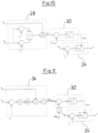
- the supply current qs determined in this way is supplied as an input variable to a limiting controller 30, in which the supply current qs determined in this way is compared with a predetermined maximum supply current q S,max .
- the limiting controller 30 outputs a maximum speed n max , which is fed to a pressure controller 32 as a manipulated variable.
- the pressure regulator 32 regulates the differential pressure across the load pump 20, ie between the inlet and outlet of the load pump 20. This is the differential pressure Dp L across the load circuit 2.
- the pressure regulator 32 regulates this differential pressure to a setpoint differential pressure Dp set .
- the pressure controller 32 outputs a speed n as an output variable, with which the load pump 20, which has a speed-controllable drive motor, is operated.
- the maximum speed n max specified by the limiting controller is taken into account in such a way that the speed n is limited to this maximum value. i.e. the load pump 20 is thus operated at the maximum speed n max specified by the limiting controller 30, so that the load current q L and thus indirectly also the supply current qs are limited.
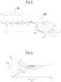
- FIG. 12 shows another example for linking a plurality of controllers, the supply current qs not being used directly here, but instead the heat flow dQ calc in a heat flow determination module 34 .
- the load current q L , the load inlet temperature T L and the load outlet temperature T R are also taken into account to determine the heat flow dQ calc .
- the absolute or total heat flow dQ calc which is supplied via the supply line 10 in the load circuit, can be calculated.
- this heat flow dQ calc is compared with a maximum heat flow dQ max , which is specified.
- the limiting controller 30' outputs a maximum speed n max for the load pump 20, which is then fed to the pressure controller 32, as was described above.
- the supply current qs is limited in this way, since the supply current qs is also indirectly limited by limiting the speed of the load pump 20 .
- c p is the specific heat capacity of the heat transfer medium, ie fluid that flows through the system as a heat transfer medium.
- rho is density or mass density this fluid. From the presentation in 4 it can be seen that the load current q L can be reduced or limited by limiting the heat flow dQ calc .
- T R1 , T R2 and T R3 constant return temperature curves of a radiator or heat exchanger, which z. B. can also be a floor heating circuit. If such a radiator is operated with a specific load-inlet temperature curve T L , the load current q L can be reduced by reducing the heat flow dQ by the amount DdQ and by a relatively large amount Dq L .
- the load current can be determined directly in the load pump 20 . This is done by calculating or estimating based on operating parameters of the load pump 20, namely the current speed n and the differential pressure Dp across the load pump or based on the speed n and the electrical power P consumed by the drive motor of the load pump 20.
- Figure 5a shows a diagram in which the differential pressure Dp is compared to the flow rate q for different speeds n 1 and n 2 . It can be seen that if the speed and the differential pressure Dp are known, the load current q L can be calculated if the pump characteristic curves shown are known. Correspondingly shows Figure 5b the electrical power P is plotted against the flow rate q. Known characteristic curves for the speeds n 1 and n 2 are also plotted in this diagram. Here, too, it can be seen that with known characteristic curves of the pump from the speed n and the electrical power P the load current q L can be determined. A special flow sensor for detecting the load current q L can thus be dispensed with.
- the limiting controller 30" can limit the load output temperature T R at the output 16 of the load circuit 2 to a limit value T R0 .
- the limiting controller 30" outputs a maximum speed n max to the pressure controller 32, which is configured in the same way as it is based on figures 2 and 3 was described.
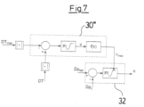
- the controller arrangement which is shown in 7 is shown.
- the temperature difference DT across the load circuit ie the difference between the load inlet temperature T L and the load outlet temperature T R , is kept above or below a predetermined limit value DT max with this controller.
- the load current qL
- the supply current qs will decrease, so that an indirect limitation of the supply current qs for hydraulic compensation is possible.
- the values of the maximum temperature difference DT max and the detected temperature difference DT are taken into account as amounts without a sign, so that this controller can be used in the same configuration for heating as well as for cooling systems. If the temperature difference exceeds that Limit DT max reached, the limiting controller 30 ′′′ outputs a maximum speed n max to the pressure controller 32, as is the case above with reference to the figures 2 , 3 and 6 was described. Here, too, the speed of the pump and thus the load current q L and at the same time the supply current qs are limited.
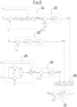
- FIG. 8 now shows a combination of several of the controllers described above. So is up in figure 8 First, the heat flow determination module 34 is shown with the limiting controller 30'. In the middle, the limiter is 30" off 6 shown. In 8 below is the arrangement of the supply current determination module 28 with the limit controller 30 off 2 shown.
- the limiting controller 30' outputs a maximum speed n max1
- the limiting controller 30" outputs a maximum speed n max2
- the limiting controller 30 outputs a maximum speed n max3 for the load pump.
- These three maximum speeds n max1 , n max2 and n max3 are assigned to a selection controller 36 or to a selection device 36, in which one of these several maximum speeds is selected.
- this is the smallest of the three maximum speeds n max1 , n max2 and n max3 figures 2 , 6 and 3 described, transferred to the pressure controller 32 as a manipulated variable or maximum speed, so that the speed n output by the pressure controller 32 is limited to the lowest value of the three maximum speeds n max1 , n max2 and n max3 determined in this way.
- the selection controller 36 it could also be designed so that the largest of these three speeds is selected.
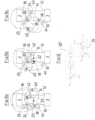
- FIGS 9a - 9c now show three examples of load circuits 2 with associated mixing circuits of a heat transfer system, it being understood that several such arrangements of load circuits can be present in the heat transfer system.
- the arrangement in Figure 9a corresponds essentially to the in 1 arrangement shown.
- the supply 3 includes the feed 6 and the return 8 and are only shown here in simplified form.
- a flow sensor 38 is also arranged here in the inlet to the load circuit 2, which sensor detects the load current q L .
- the load current q L can also be determined directly in the load pump 20, as described above.
- a temperature controller 24 which the load input temperature T L by setting the mixing valve 22 in the basis of 1 described manner regulates.
- the arrangement also contains a compensation controller in the form of a control module 40 for limiting the supply current qs in the manner described above.
- the rule module 40 receives, as in Figure 9a is shown, the input variables are the load current q L , the load input temperature T L , the supply input temperature Ts and the load output temperature T R , which is detected here not directly at the output 16 but in the mixing line 14 by a temperature sensor.
- the temperature sensor 42 for detecting the load output temperature T R could also be arranged at the output 16 .
- the temperature at the outlet 16 essentially corresponds to the temperature in the mixing line 14 .
- the supply inlet temperature Ts is detected by a temperature sensor 44 in the supply line 10 .
- the controller 40 includes a controller arrangement, as shown on the basis of figures 2 , 3 , 6 , 7 and or 8 was described and outputs the speed at which the load pump 20 is operated via the pressure controller 32 also contained in the control module 40 . Since the rotational speed n is limited to a maximum value in the manner described by the control modules mentioned, the supply current qs is also limited to a maximum via the control module 40 in the manner described above.
- Figure 9b shows an alternative arrangement, which differs from the design according to FIG Figure 9a differs in that the mixing valve 22 'as 3/2-way valve is arranged directly in the mixing point 18.
- the temperature regulator 24 controls this mixing valve 22' to regulate the load inlet temperature T L .
- the additional control module 40 corresponds to that shown in FIG Figure 9a described control module.
- the load current q L is not determined via a separate sensor, but via the load pump 20 or its operating parameters, as described above.
- the control module 40 limits the supply current qs by limiting the speed n of the load pump 20, as described above.
- a third variant of the load circuit 2 with a mixing circuit of a heat transfer system according to the invention is in 9c shown.
- the embodiment shown there corresponds to that in Figure 9b shown embodiment with the difference that the mixing valve 22 'is omitted and instead in the supply line 10 a supply pump 46 is arranged.
- the speed of the supply pump 46 is controlled by the temperature controller 24 in order to control the load input temperature T L to a predetermined or desired value. i.e.
- the supply flow qs, which is supplied to the mixing point 18, is regulated via the supply pump 45. If the load current q L which is generated by the load pump 20 is greater than the supply current qs, the load pump 20 additionally generates a mixed current via the mixed line 14 .
- control module 40 causes a limitation of the supply current qs in the manner described above by the speed n of the load pump 20, as based on the figures 2 , 3 , 6 , 7 and/or 8 explained, limited. If the speed n of the load pump 20 is limited or reduced in this way, the load current q L decreases. If the supply pump 46 initially supplies an unchanged supply flow qs, this means that the admixture or the mixed flow via the mixing line decreases and the load input temperature T L therefore increases. This will then cause the temperature controller 24 to decrease the supply current qs again, to lower the temperature. In this way, the supply current qs is also indirectly reduced by limiting the speed n of the load pump 20.
- the manipulated variable of the temperature controller 24 could also be influenced in the same way as based on the Figures 10 - 13 is explained.
- a limiting controller 30 is also arranged on the output side, as is illustrated in FIG 2 was described and limits the supply current qs to a maximum supply current q S,max .
- the limiting controller 30 does not output a maximum speed as the manipulated variable, but rather a maximum manipulated variable u max , which is transferred to the temperature controller 24 .
- the temperature controller 24 is used to regulate the load input temperature to a target temperature T ref .
- T ref For this purpose, it outputs a manipulated variable u, which represents the degree of valve opening of the valve 22, 22' or the speed of the supply pump qs.
- the temperature controller 24 limits the manipulated variable u to the maximum manipulated variable u max specified by the limiting controller 30, so that when the mixing valve 22, 22′ or the supply pump 46 is adjusted accordingly, the supply flow qs is thus indirectly limited.
- FIG 11 shows a controller arrangement, which according to the controller arrangement 3 corresponds, except that the pressure controller 32 is also replaced by the temperature controller 24 here.
- the above based on 3 described limiting controller 30 ', as previously with reference to 10 described, does not output a maximum speed, but a maximum manipulated variable u max , via which temperature controller 24 is described in FIG Way the manipulated variable u is limited to this maximum value u max .
- FIG 12 shows a controller arrangement which corresponds to the controller arrangement which is based on FIG 6 was described, with the difference that here too the pressure controller 32 is replaced by the pressure controller 24, which is supplied by the limiting controller 30" as a limiting manipulated variable, a maximum manipulated variable u max .
- the temperature controller 24 thus limits the manipulated variable u that is output to this value.
- FIG. 13 shows a controller arrangement, which the basis of 7 corresponds to the controller arrangement described, with the difference that here too the pressure controller 32 is replaced by the temperature controller 24, to which a maximum manipulated variable u max is supplied by the limiting controller 30′′′, as above with reference to FIG Figures 10 - 12 was described.
- a selection controller is also provided, which from three maximum manipulated variables u max1 , u max2 and u max3 in the basis of 8 the manner described selects the largest or smallest manipulated variable and transfers it to the temperature controller 24 .
- FIGS. 14a - 14c now show similar to that Figures 9a - 9c three exemplary embodiments of a part of a heat transfer system for the realization of the control principles, which are based on Figures 10 - 13 are described.
- the design corresponds to 14a basically according to the arrangement Figure 9a , the design according to Figure 14b according to the design Figure 9b and the design according to Figure 14c according to the design 9c .
- This relates in particular to the arrangement of the mixing valves 22 and 22′ and the supply pump 46 and the temperature sensors and the flow sensor 38.
- the description according to FIG Figures 9a - 9c referred.
- FIG. 14a - 14c Also with regard to the arrangements contained in Figures 14a - 14c are shown, it is to be understood that in a heat transfer system there are preferably several such arrangements of load circuits 2 with associated mixing devices.
- control principle according to the invention could also be used in heat transfer systems which use a heat exchanger instead of a mixing device.
- a heat exchanger instead of the mixing line 14, a heat exchanger would be provided, with the supply flow qs flowing through the supply line 10 and the return line 12 through a first flow path of the heat exchanger, and the load flow q L flowing through the load circuit 2 through a second flow path preferably both a load pump 20 in the load circuit and a supply pump 46 are provided in the supply circuit.
- control module 40 and/or the temperature controller 24 are particularly preferred preferably integrated into the pump unit forming the load pump 20, in particular in a terminal box or electronics housing of this pump unit.
Landscapes
- Engineering & Computer Science (AREA)
- Physics & Mathematics (AREA)
- Thermal Sciences (AREA)
- Chemical & Material Sciences (AREA)
- Combustion & Propulsion (AREA)
- Mechanical Engineering (AREA)
- General Engineering & Computer Science (AREA)
- Air Conditioning Control Device (AREA)
- Control Of Temperature (AREA)
Claims (17)
- Procédé de limitation du débit d'alimentation (qS) dans un système de transmission de chaleur qui comprend un conduit d'alimentation (10) avec un débit d'alimentation (qS) et une température d'alimentation d'entrée (TS) et au moins un circuit de charge (2) avec une pompe de charge (20) qui produit un débit de charge (qL) passant par ledit au moins un circuit de charge (2) avec une température d'entrée de charge (TL) et une température de sortie de charge (TR), la température d'entrée de charge (TL) étant réglée par un changement du débit d'alimentation (qS),
caractérisé en ce que
le débit d'alimentation (qS) est limité, outre pour le réglage en fonction de la température d'entrée de charge (TL) souhaitée, à un débit maximal (qS,max) en tenant compte d'au moins une température mesurée dans ledit au moins un circuit de charge (2), en ne pas mesurant le débit d'alimentation (qS) directement lui-même, mais en le déterminant de façon indirecte sur la base de la température mesurée dans ledit au moins un circuit de charge (2) et en le comparant avec une valeur maximale souhaitée, si bien que, pour chaque circuit de charge, un débit d'alimentation (qS) maximal déterminé ne soit pas dépassé. - Procédé selon la revendication 1, caractérisé en ce que le système de transmission de chaleur comprend au moins un échangeur thermique entre le conduit d'alimentation (10) et le circuit de charge (2), et que la température dans le circuit de charge (2) est modifié au moyen d'un changement du débit dans le conduit d'alimentation (10).
- Procédé selon la revendication 1 ou 2, caractérisé en ce que le système de transmission de chaleur comprend au moins un dispositif mélangeur (14, 18) qui mélange, au moins en partie, un débit de charge de sortie (qL) avec le débit d'alimentation (qS).
- Procédé selon l'une des revendications précédentes, caractérisé en ce que le débit d'alimentation (qS) est réglé sur la base du débit de charge (qL) et d'un ou de plusieurs signaux de température qui sont déterminés dans le système de transmission de chaleur, notamment sur la base de la température d'entrée d'alimentation (TS), de la température d'entrée de charge (TL) et de la température de sortie de charge (TR).
- Procédé selon l'une des revendications précédentes, caractérisé en ce que le débit d'alimentation (qS) est indirectement limité par au moins une des mesures suivantes :- limitation du circuit de puissance (dQ) thermique dans le circuit de charge (2),- limitation de la température de sortie de charge (TR),- limitation de la différence (DT) entre la température de sortie de charge (TR) et la température d'entrée de charge (TL).
- Procédé selon l'une des revendications précédentes, caractérisé en ce que, pour au moins deux variables d'entrées, un débit d'alimentation maximal (qS) ou une variable (n ; u) se trouvant en rapport monotone par rapport au débit maximal d'alimentation (qS) est déterminé sur la base d'une des variables d'entrée et que, ensuite, un des débits d'alimentation (qS,max) maximaux ainsi déterminés est choisi pour limiter le débit d'alimentation (qS).
- Procédé selon l'une des revendications précédentes, caractérisé en ce que le débit d'alimentation (qS) est limité par la limitation de la vitesse de rotation (n) de la pompe de charge (20) et/ou la vitesse de rotation d'une pompe d'alimentation (46) et/ou par la limitation du degré d'ouverture (u) d'une vanne (22 ; 22')
- Procédé selon l'une des revendications précédentes, caractérisé en ce que le débit d'alimentation (qS) est limité par la limitation d'une variable de réglage (n ; u) d'un régulateur de pression ou de température (32, 24).
- Procédé selon l'une des revendications précédentes, caractérisé en ce que le débit d'alimentation (qS) est limité par une limitation d'une variante de réglage (n ; u) d'une boucle de réglage qui régule une température de charge et/ou une pression de charge dans le circuit de charge (2) notamment une pression différentielle (Dp) à la pompe de charge (20).
- Système de transmission de chaleur comprenantun conduit d'alimentation (10) destiné au raccordement à une alimentation en fluide (6) et un conduit de retour (12) pour un raccordement à un retour de fluide (8),et au moins un circuit de charge (2) avec une pompe de charge (20) installée dans ce dernier, qui engendre un débit de charge (qL) passant par ledit au moins un circuit de charge (2), un dispositif de régulation de débit (24) pour réguler un débit d'alimentation (qS) dans le conduit d'alimentation (10), le dispositif de régulation de débit (24) étant conçu de façon qu'il régule une température d'entrée de charge (TL) à l'entrée dudit au moins un circuit de charge (2) par une régulation du débit d'alimentation (qS),caractérisé parau moins un capteur de température dans ledit au moins un circuit de charge (2) et au moins un régulateur de limitation (30) qui est conçu de façon qu'il limite le débit d'alimentation (qS) directement ou indirectement à un maximum prédéterminé en fonction d'au moins un signal de température provenant dudit au moins un capteur de température, en déterminant le débit d'alimentation (qS) indirectement et en le limitant de façon que le débit d'alimentation (qS) vers un circuit de charge (2) individuel ne dépasse pas une valeur maximale préréglée.
- Système de transmission de chaleur selon la revendication 11, caractérisé par un échangeur de chaleur entre le conduit d'alimentation (10) et le circuit de charge (2) ou par un conduit de mélange (14) qui relie la sortie (16) du circuit de charge (2) au conduit d'alimentation (10) à un point de mélange (18).
- Système de transmission de chaleur selon l'une des revendications 10 ou 11, caractérisé par un régulateur de pression (32) et/ou de température (24) pour le circuit de charge (2), ce régulateur (32, 24) étant accouplé au régulateur de limitation (30) de manière telle qu'une variante de réglage (n, u) puisse être limitée par le régulateur de limitation (30) à une valeur maximale (nmax, umax), dans le régulateur de pression (32) et/ou de température (24).
- Système de transmission de chaleur selon l'une des revendications 10 à 12, caractérisé en ce que le régulateur de limitation (30) est formé de manière telle qu'il compare un débit de puissance thermique (dQ) dans le circuit de charge (2) et/ou la température de sortie de charge (TR) et/ou une différence (DT) entre la température de sortie de charge (TR) et la température d'entrée de charge (TL), avec la valeur limite correspondante, et qu'il définisse un maximum pour une variable (n, u) pour le réglage du débit d'alimentation (qS).
- Système de transmission de chaleur selon l'une des revendications 10 à 13, caractérisé en ce que ledit au moins un capteur de température est un capteur de température (25) qui est placé à l'entrée du circuit de charge (2) et saisit une température d'entrée de charge (TL), ou est un capteur de température qui est placé à la sortie (16) du circuit de charge (2) et saisit une température de sortie de charge (TR).
- Système de transmission de chaleur selon l'une des revendications 10 à 14, caractérisé en ce que le dispositif de régulation de débit comprend au moins une pompe d'alimentation (46) régulant le débit d'alimentation (qS) et/ou une vanne d'alimentation (22, 22') régulant le débit d'alimentation (qS).
- Système de transmission de chaleur selon l'une des revendications 10 à 15, caractérisé en ce que la pompe de charge (20) est formée pour capter un débit (qL) passant par le circuit de charge (2) et est de préférence relié au dispositif de régulation de débit pour la transmission d'un signal correspondant au débit (qL) capté.
- Système de transmission de chaleur selon l'une des revendications 10 à 16, caractérisé en ce que le dispositif de régulation de débit (24, 32) et/ou le régulateur de limitation (30) sont intégrés dans un groupe motopompe de charge formant la pompe de charge (20).
Priority Applications (4)
| Application Number | Priority Date | Filing Date | Title |
|---|---|---|---|
| EP14173714.8A EP2960587B1 (fr) | 2014-06-24 | 2014-06-24 | Procédé de limitation du débit d'alimentation dans un système de transmission de chaleur |
| RU2015124599A RU2682976C2 (ru) | 2014-06-24 | 2015-06-23 | Способ ограничения питающего потока в системе теплопередачи |
| US14/747,370 US10184671B2 (en) | 2014-06-24 | 2015-06-23 | Method for limiting a supply flow in a heat transfer system |
| CN201510355136.9A CN105318772B (zh) | 2014-06-24 | 2015-06-24 | 用于在传热系统中限制供给通量的方法 |
Applications Claiming Priority (1)
| Application Number | Priority Date | Filing Date | Title |
|---|---|---|---|
| EP14173714.8A EP2960587B1 (fr) | 2014-06-24 | 2014-06-24 | Procédé de limitation du débit d'alimentation dans un système de transmission de chaleur |
Publications (3)
| Publication Number | Publication Date |
|---|---|
| EP2960587A1 EP2960587A1 (fr) | 2015-12-30 |
| EP2960587C0 EP2960587C0 (fr) | 2023-06-07 |
| EP2960587B1 true EP2960587B1 (fr) | 2023-06-07 |
Family
ID=50982800
Family Applications (1)
| Application Number | Title | Priority Date | Filing Date |
|---|---|---|---|
| EP14173714.8A Active EP2960587B1 (fr) | 2014-06-24 | 2014-06-24 | Procédé de limitation du débit d'alimentation dans un système de transmission de chaleur |
Country Status (4)
| Country | Link |
|---|---|
| US (1) | US10184671B2 (fr) |
| EP (1) | EP2960587B1 (fr) |
| CN (1) | CN105318772B (fr) |
| RU (1) | RU2682976C2 (fr) |
Families Citing this family (20)
| Publication number | Priority date | Publication date | Assignee | Title |
|---|---|---|---|---|
| US9625222B2 (en) * | 2012-02-02 | 2017-04-18 | Semco Llc | Chilled beam pump module, system, and method |
| KR101577811B1 (ko) * | 2013-08-27 | 2015-12-15 | 주식회사 경동나비엔 | 에어 핸들러 시스템의 난방 중 온수사용 판단방법 |
| US10161639B2 (en) * | 2015-03-10 | 2018-12-25 | Joseph Copeland | Heat transfer apparatus and heat transfer system for masonry heater |
| DE102015014378A1 (de) | 2015-11-09 | 2017-05-11 | Wilo Se | Verfahren zur Regelung einer Kreiselpumpe sowie zugehöriges Pumpensystem |
| US11156371B2 (en) * | 2016-01-22 | 2021-10-26 | The Marley Company Llc | Networked boilers and control method |
| RU2624428C1 (ru) * | 2016-04-04 | 2017-07-03 | Федеральное государственное автономное образовательное учреждение высшего образования "Белгородский государственный национальный исследовательский университет" (НИУ "БелГУ") | Устройство для пофасадного регулирования температуры воздуха в помещении |
| US12044421B2 (en) | 2016-06-08 | 2024-07-23 | Semco Llc | Air conditioning with recovery wheel, dehumidification wheel, cooling coil, and secondary direct-expansion circuit |
| US10697650B2 (en) * | 2016-07-27 | 2020-06-30 | Computime Ltd. | Automatic balance valve control |
| EP3372903A1 (fr) * | 2017-03-07 | 2018-09-12 | E.ON Sverige AB | Ensemble de consommateur d'énergie thermique local et ensemble générateur d'énergie thermique local pour un système de distribution d'énergie thermique de district |
| DE102017116079A1 (de) * | 2017-07-18 | 2019-01-24 | Eisenmann Se | Versorgungskreis für ein Wärmeträgermedium für einen Verbraucher, Industrieanlage und Verfahren zum Betreiben von solchen |
| CN108361987A (zh) * | 2018-02-10 | 2018-08-03 | 高安市清河油脂有限公司 | 一种电加热油炉供热系统 |
| DE102018129617A1 (de) * | 2018-11-23 | 2020-05-28 | SBK Siegfried Böhnisch Kunststofftechnik GmbH | Verfahren zur Regelung von Volumenströmen einer Flüssigkeit in Flüssigkeits-Rohrleitungen von Heizkreisen eines Heiz- und/oder Kühlsystems und Vorrichtung zur Durchführung des Verfahrens |
| EP3734396B1 (fr) * | 2019-04-29 | 2021-09-08 | Grundfos Holding A/S | Système de commande et procédé de commande d'un système de distribution de fluide |
| DE102019004838A1 (de) * | 2019-07-12 | 2021-01-14 | KSB SE & Co. KGaA | Verfahren zur Steuerung einer Anordnung aus Heizungspumpe und Drei-Wege-Mischerventil |
| CA3151866A1 (fr) | 2021-03-12 | 2022-09-12 | Semco Llc | Systeme de poutre climatique multizone et methode avec un module de pompe |
| BE1030935B1 (nl) * | 2022-10-03 | 2024-04-29 | Renson Ventilation Nv | Een verwarmings- en/of koelingssysteem voor collectieve residentiële wooneenheden, een sturingsinrichting daarvoor en een werkwijze voor het aansturen daarvan |
| WO2024105026A1 (fr) * | 2022-11-14 | 2024-05-23 | Grundfos Holding A/S | Procédé et système de commande d'un écoulement de fluide dans une boucle de mélange |
| EP4556800A1 (fr) * | 2023-11-20 | 2025-05-21 | BDR Thermea Group B.V. | Mode d'équilibrage hydronique dans un système de chauffage multi-source |
| EP4664019A1 (fr) * | 2024-06-10 | 2025-12-17 | Siemens Schweiz AG | Commande de chauffage, ventilation, climatisation |
| WO2026104158A1 (fr) * | 2024-11-18 | 2026-05-21 | Grundfos Holding A/S | Procédé de commande d'un système de mélange pour un système hydronique, système de mélange pour un système hydronique et un système hydronique |
Citations (2)
| Publication number | Priority date | Publication date | Assignee | Title |
|---|---|---|---|---|
| EP0892223A2 (fr) * | 1997-07-14 | 1999-01-20 | Electrowatt Technology Innovation AG | Dispositif de commande et de régulation pour système de chauffage |
| DE19842174A1 (de) * | 1998-09-15 | 2000-03-16 | Wilo Gmbh | Pumpenregelung |
Family Cites Families (18)
| Publication number | Priority date | Publication date | Assignee | Title |
|---|---|---|---|---|
| ATE17884T1 (de) * | 1980-05-13 | 1986-02-15 | Trucktonics Ltd | Kommunales heisswasser- versorgungssystem. |
| DE3417935A1 (de) * | 1984-05-15 | 1985-11-21 | Helmut 7100 Heilbronn Bälz | Verfahren zur messung des waermeverbrauches und gegebenenfalls zur begrenzung des massenstroms bei wenigstens einem waermeverbraucher |
| DE19506628A1 (de) * | 1995-02-25 | 1996-08-29 | Tekmar Elektronik Gmbh & Co | Verfahren und Anordnung zur Regelung eines Niedertemperatur-Heizsystems |
| DE19525887C2 (de) * | 1995-07-15 | 2002-06-27 | Grundfos As | Verfahren zur Anpassung des hydraulischen Leistungsfeldes eines Kreiselpumpenaggregates an die Erfordernisse einer Heizungsanlage |
| DE19912588A1 (de) * | 1999-03-20 | 2000-09-21 | Ksb Ag | Fluidtransportsystem |
| RU16673U1 (ru) * | 2000-07-21 | 2001-01-27 | Нижегородский региональный учебно-научный инновационный центр энергосбережения при Нижегородском государственном техническом университете | Система отопления индивидуального теплового пункта |
| US6688129B2 (en) * | 2001-08-01 | 2004-02-10 | Ronald S Ace | Geothermal space conditioning |
| KR101152472B1 (ko) * | 2006-05-19 | 2012-07-03 | 엘지전자 주식회사 | 지열을 이용한 공기조화기 |
| NL1032598C2 (nl) * | 2006-09-29 | 2009-02-25 | Kamstrup B V | Inrichting, systeem en werkwijze voor het besturen van een verwarmingssysteem. |
| JP5055177B2 (ja) * | 2008-03-24 | 2012-10-24 | 矢崎総業株式会社 | 負荷回路の保護装置 |
| US20110114284A1 (en) * | 2009-11-17 | 2011-05-19 | John Siegenthaler | Optimizing the efficiency and energy usage of a geothermal multiple heat pump system |
| US9341396B2 (en) * | 2010-04-16 | 2016-05-17 | Energy Recovery Systems Inc. | Retro-fit energy exchange system for transparent incorporation into a plurality of existing energy transfer systems |
| CN102607146B (zh) * | 2012-04-06 | 2014-09-10 | 谭仲禧 | 一种中央空调系统及其控制方法 |
| JP5984703B2 (ja) * | 2013-01-31 | 2016-09-06 | 三菱重工業株式会社 | 熱源システム及び冷却水供給装置の制御装置並びに制御方法 |
| US9658628B2 (en) * | 2013-03-15 | 2017-05-23 | Schneider Electric Buildings, Llc | Advanced valve actuator with true flow feedback |
| EP2871539B1 (fr) * | 2013-11-07 | 2019-04-17 | Grundfos Holding A/S | Procédé de diagnostic pour le diagnostic du fonctionnement correct d'un système de chauffage et/ou de refroidissement |
| DK2874039T3 (en) * | 2013-11-19 | 2017-07-17 | Grundfos Holding As | Method of controlling a heat transfer system as well as such a heat transfer system |
| DK2985536T3 (en) * | 2014-08-15 | 2018-07-16 | Grundfos Holding As | Method for regulating a pump assembly |
-
2014
- 2014-06-24 EP EP14173714.8A patent/EP2960587B1/fr active Active
-
2015
- 2015-06-23 RU RU2015124599A patent/RU2682976C2/ru active
- 2015-06-23 US US14/747,370 patent/US10184671B2/en active Active
- 2015-06-24 CN CN201510355136.9A patent/CN105318772B/zh active Active
Patent Citations (2)
| Publication number | Priority date | Publication date | Assignee | Title |
|---|---|---|---|---|
| EP0892223A2 (fr) * | 1997-07-14 | 1999-01-20 | Electrowatt Technology Innovation AG | Dispositif de commande et de régulation pour système de chauffage |
| DE19842174A1 (de) * | 1998-09-15 | 2000-03-16 | Wilo Gmbh | Pumpenregelung |
Also Published As
| Publication number | Publication date |
|---|---|
| EP2960587C0 (fr) | 2023-06-07 |
| RU2682976C2 (ru) | 2019-03-25 |
| CN105318772A (zh) | 2016-02-10 |
| RU2015124599A3 (fr) | 2019-01-21 |
| CN105318772B (zh) | 2020-01-07 |
| US10184671B2 (en) | 2019-01-22 |
| RU2015124599A (ru) | 2017-01-10 |
| EP2960587A1 (fr) | 2015-12-30 |
| US20150369494A1 (en) | 2015-12-24 |
Similar Documents
| Publication | Publication Date | Title |
|---|---|---|
| EP2960587A1 (fr) | Procédé de limitation du débit d'alimentation dans un système de transmission de chaleur | |
| EP1163478B1 (fr) | Systeme de transport fluidique | |
| EP2874039B1 (fr) | Procédé de commande pour un système de transmission de chaleur et système de transmission de chaleur de ce type | |
| EP2753999B1 (fr) | Procédé pour faire fonctionner et/ou surveiller une installation hvac | |
| EP2870414B1 (fr) | Procédé pour le fonctionnement d'un échangeur thermique ainsi qu'installation hvac pour la réalisation du procédé | |
| DE102015121418B3 (de) | Verfahren zum automatischen hydraulischen Abgleich von Verbrauchern in einer Heizungs- und/oder Kühlanlage | |
| EP2863134A1 (fr) | Procédé d'adaptation d'une courbe de chauffe | |
| EP2187136A2 (fr) | Procédé de fonctionnement d'un système de transport d'énergie thermique sur un support fluide | |
| EP3026352A1 (fr) | Procede de regulation hydraulique de plusieurs circuits de chauffe sur nourrices de distribution | |
| EP3412978B1 (fr) | Procédé de commande d'un système de refroidissement et/ou de chauffage | |
| EP2636959B1 (fr) | Réglage de radiateur | |
| WO2023170138A1 (fr) | Système de pile à combustible, véhicule, procédé de commande d'un ensemble pile à combustible et programme informatique | |
| EP3101352A1 (fr) | Procede de fonctionnement d'une installation de chauffage et dispositif de regulation comprenant un capteur de difference de pression | |
| EP3369934B1 (fr) | Pompe de circulation | |
| DE3203832A1 (de) | Verfahren und regelvorrichtung zum regeln eines heizungskreises | |
| EP1191287A2 (fr) | Système de tuyauterie pour l'échange d'énergie thermique | |
| WO2023186783A1 (fr) | Procédé de commande de système de chauffage, système de chauffage et dispositif de commande | |
| DE102010055080A1 (de) | Verfahren zur Optimierung der Vorlaufsolltemperatur eines Heizfluids und Heizsystem zur Beheizung von zumindest zwei separaten Räumen | |
| DE10259279B3 (de) | Versorgungssystem für Heiz-oder Kühlwasser sowie Verfahren zum Betreiben desselben | |
| EP3997389B1 (fr) | Procédé de commande d'un ensemble composé d'une pompe de chauffage et d'une vanne mélangeuse à trois voies | |
| EP3025100B1 (fr) | Système de chauffage et procédé de fonctionnement de ce système | |
| EP2638447B1 (fr) | Dispositif de réglage d'une température individuelle de fonctionnement des composants d'une machine-outil | |
| EP1321842B1 (fr) | Système hydraulique | |
| EP4230921A1 (fr) | Procédé de commande d'une température ambiante, système de chauffage pour commander une température ambiante et dispositif de commande destiné à être utilisé dans un système de chauffage | |
| EP3350515B1 (fr) | Procédé et dispositif de régulation de la température d'un milieu porteur fluide |
Legal Events
| Date | Code | Title | Description |
|---|---|---|---|
| PUAI | Public reference made under article 153(3) epc to a published international application that has entered the european phase |
Free format text: ORIGINAL CODE: 0009012 |
|
| AK | Designated contracting states |
Kind code of ref document: A1 Designated state(s): AL AT BE BG CH CY CZ DE DK EE ES FI FR GB GR HR HU IE IS IT LI LT LU LV MC MK MT NL NO PL PT RO RS SE SI SK SM TR |
|
| AX | Request for extension of the european patent |
Extension state: BA ME |
|
| 17P | Request for examination filed |
Effective date: 20160627 |
|
| RBV | Designated contracting states (corrected) |
Designated state(s): AL AT BE BG CH CY CZ DE DK EE ES FI FR GB GR HR HU IE IS IT LI LT LU LV MC MK MT NL NO PL PT RO RS SE SI SK SM TR |
|
| STAA | Information on the status of an ep patent application or granted ep patent |
Free format text: STATUS: EXAMINATION IS IN PROGRESS |
|
| 17Q | First examination report despatched |
Effective date: 20161221 |
|
| GRAP | Despatch of communication of intention to grant a patent |
Free format text: ORIGINAL CODE: EPIDOSNIGR1 |
|
| STAA | Information on the status of an ep patent application or granted ep patent |
Free format text: STATUS: GRANT OF PATENT IS INTENDED |
|
| INTG | Intention to grant announced |
Effective date: 20201113 |
|
| GRAJ | Information related to disapproval of communication of intention to grant by the applicant or resumption of examination proceedings by the epo deleted |
Free format text: ORIGINAL CODE: EPIDOSDIGR1 |
|
| STAA | Information on the status of an ep patent application or granted ep patent |
Free format text: STATUS: EXAMINATION IS IN PROGRESS |
|
| INTC | Intention to grant announced (deleted) | ||
| GRAP | Despatch of communication of intention to grant a patent |
Free format text: ORIGINAL CODE: EPIDOSNIGR1 |
|
| STAA | Information on the status of an ep patent application or granted ep patent |
Free format text: STATUS: GRANT OF PATENT IS INTENDED |
|
| INTG | Intention to grant announced |
Effective date: 20220914 |
|
| GRAS | Grant fee paid |
Free format text: ORIGINAL CODE: EPIDOSNIGR3 |
|
| GRAA | (expected) grant |
Free format text: ORIGINAL CODE: 0009210 |
|
| STAA | Information on the status of an ep patent application or granted ep patent |
Free format text: STATUS: THE PATENT HAS BEEN GRANTED |
|
| AK | Designated contracting states |
Kind code of ref document: B1 Designated state(s): AL AT BE BG CH CY CZ DE DK EE ES FI FR GB GR HR HU IE IS IT LI LT LU LV MC MK MT NL NO PL PT RO RS SE SI SK SM TR |
|
| REG | Reference to a national code |
Ref country code: GB Ref legal event code: FG4D Free format text: NOT ENGLISH |
|
| REG | Reference to a national code |
Ref country code: CH Ref legal event code: EP Ref country code: AT Ref legal event code: REF Ref document number: 1576152 Country of ref document: AT Kind code of ref document: T Effective date: 20230615 Ref country code: DE Ref legal event code: R096 Ref document number: 502014016582 Country of ref document: DE |
|
| U01 | Request for unitary effect filed |
Effective date: 20230707 |
|
| U07 | Unitary effect registered |
Designated state(s): AT BE BG DE DK EE FI FR IT LT LU LV MT NL PT SE SI Effective date: 20230718 |
|
| U1O | Appointed representative for the unitary patent procedure deleted after the registration of the unitary effect | ||
| REG | Reference to a national code |
Ref country code: LT Ref legal event code: MG9D |
|
| U20 | Renewal fee for the european patent with unitary effect paid |
Year of fee payment: 10 Effective date: 20230914 |
|
| PG25 | Lapsed in a contracting state [announced via postgrant information from national office to epo] |
Ref country code: NO Free format text: LAPSE BECAUSE OF FAILURE TO SUBMIT A TRANSLATION OF THE DESCRIPTION OR TO PAY THE FEE WITHIN THE PRESCRIBED TIME-LIMIT Effective date: 20230907 Ref country code: ES Free format text: LAPSE BECAUSE OF FAILURE TO SUBMIT A TRANSLATION OF THE DESCRIPTION OR TO PAY THE FEE WITHIN THE PRESCRIBED TIME-LIMIT Effective date: 20230607 |
|
| PG25 | Lapsed in a contracting state [announced via postgrant information from national office to epo] |
Ref country code: RS Free format text: LAPSE BECAUSE OF FAILURE TO SUBMIT A TRANSLATION OF THE DESCRIPTION OR TO PAY THE FEE WITHIN THE PRESCRIBED TIME-LIMIT Effective date: 20230607 Ref country code: HR Free format text: LAPSE BECAUSE OF FAILURE TO SUBMIT A TRANSLATION OF THE DESCRIPTION OR TO PAY THE FEE WITHIN THE PRESCRIBED TIME-LIMIT Effective date: 20230607 Ref country code: GR Free format text: LAPSE BECAUSE OF FAILURE TO SUBMIT A TRANSLATION OF THE DESCRIPTION OR TO PAY THE FEE WITHIN THE PRESCRIBED TIME-LIMIT Effective date: 20230908 |
|
| PG25 | Lapsed in a contracting state [announced via postgrant information from national office to epo] |
Ref country code: SK Free format text: LAPSE BECAUSE OF FAILURE TO SUBMIT A TRANSLATION OF THE DESCRIPTION OR TO PAY THE FEE WITHIN THE PRESCRIBED TIME-LIMIT Effective date: 20230607 |
|
| PG25 | Lapsed in a contracting state [announced via postgrant information from national office to epo] |
Ref country code: IS Free format text: LAPSE BECAUSE OF FAILURE TO SUBMIT A TRANSLATION OF THE DESCRIPTION OR TO PAY THE FEE WITHIN THE PRESCRIBED TIME-LIMIT Effective date: 20231007 |
|
| PG25 | Lapsed in a contracting state [announced via postgrant information from national office to epo] |
Ref country code: SM Free format text: LAPSE BECAUSE OF FAILURE TO SUBMIT A TRANSLATION OF THE DESCRIPTION OR TO PAY THE FEE WITHIN THE PRESCRIBED TIME-LIMIT Effective date: 20230607 Ref country code: SK Free format text: LAPSE BECAUSE OF FAILURE TO SUBMIT A TRANSLATION OF THE DESCRIPTION OR TO PAY THE FEE WITHIN THE PRESCRIBED TIME-LIMIT Effective date: 20230607 Ref country code: RO Free format text: LAPSE BECAUSE OF FAILURE TO SUBMIT A TRANSLATION OF THE DESCRIPTION OR TO PAY THE FEE WITHIN THE PRESCRIBED TIME-LIMIT Effective date: 20230607 Ref country code: IS Free format text: LAPSE BECAUSE OF FAILURE TO SUBMIT A TRANSLATION OF THE DESCRIPTION OR TO PAY THE FEE WITHIN THE PRESCRIBED TIME-LIMIT Effective date: 20231007 Ref country code: CZ Free format text: LAPSE BECAUSE OF FAILURE TO SUBMIT A TRANSLATION OF THE DESCRIPTION OR TO PAY THE FEE WITHIN THE PRESCRIBED TIME-LIMIT Effective date: 20230607 |
|
| REG | Reference to a national code |
Ref country code: CH Ref legal event code: PL |
|
| PG25 | Lapsed in a contracting state [announced via postgrant information from national office to epo] |
Ref country code: PL Free format text: LAPSE BECAUSE OF FAILURE TO SUBMIT A TRANSLATION OF THE DESCRIPTION OR TO PAY THE FEE WITHIN THE PRESCRIBED TIME-LIMIT Effective date: 20230607 |
|
| REG | Reference to a national code |
Ref country code: DE Ref legal event code: R097 Ref document number: 502014016582 Country of ref document: DE |
|
| PG25 | Lapsed in a contracting state [announced via postgrant information from national office to epo] |
Ref country code: MC Free format text: LAPSE BECAUSE OF FAILURE TO SUBMIT A TRANSLATION OF THE DESCRIPTION OR TO PAY THE FEE WITHIN THE PRESCRIBED TIME-LIMIT Effective date: 20230607 |
|
| REG | Reference to a national code |
Ref country code: IE Ref legal event code: MM4A |
|
| PG25 | Lapsed in a contracting state [announced via postgrant information from national office to epo] |
Ref country code: MC Free format text: LAPSE BECAUSE OF FAILURE TO SUBMIT A TRANSLATION OF THE DESCRIPTION OR TO PAY THE FEE WITHIN THE PRESCRIBED TIME-LIMIT Effective date: 20230607 |
|
| PLBE | No opposition filed within time limit |
Free format text: ORIGINAL CODE: 0009261 |
|
| STAA | Information on the status of an ep patent application or granted ep patent |
Free format text: STATUS: NO OPPOSITION FILED WITHIN TIME LIMIT |
|
| PG25 | Lapsed in a contracting state [announced via postgrant information from national office to epo] |
Ref country code: IE Free format text: LAPSE BECAUSE OF NON-PAYMENT OF DUE FEES Effective date: 20230624 |
|
| PG25 | Lapsed in a contracting state [announced via postgrant information from national office to epo] |
Ref country code: IE Free format text: LAPSE BECAUSE OF NON-PAYMENT OF DUE FEES Effective date: 20230624 Ref country code: CH Free format text: LAPSE BECAUSE OF NON-PAYMENT OF DUE FEES Effective date: 20230630 |
|
| 26N | No opposition filed |
Effective date: 20240308 |
|
| U20 | Renewal fee for the european patent with unitary effect paid |
Year of fee payment: 11 Effective date: 20240625 |
|
| PG25 | Lapsed in a contracting state [announced via postgrant information from national office to epo] |
Ref country code: CY Free format text: LAPSE BECAUSE OF FAILURE TO SUBMIT A TRANSLATION OF THE DESCRIPTION OR TO PAY THE FEE WITHIN THE PRESCRIBED TIME-LIMIT; INVALID AB INITIO Effective date: 20140624 |
|
| U20 | Renewal fee for the european patent with unitary effect paid |
Year of fee payment: 12 Effective date: 20250627 |
|
| PG25 | Lapsed in a contracting state [announced via postgrant information from national office to epo] |
Ref country code: HU Free format text: LAPSE BECAUSE OF FAILURE TO SUBMIT A TRANSLATION OF THE DESCRIPTION OR TO PAY THE FEE WITHIN THE PRESCRIBED TIME-LIMIT; INVALID AB INITIO Effective date: 20140624 |
|
| PG25 | Lapsed in a contracting state [announced via postgrant information from national office to epo] |
Ref country code: TR Free format text: LAPSE BECAUSE OF FAILURE TO SUBMIT A TRANSLATION OF THE DESCRIPTION OR TO PAY THE FEE WITHIN THE PRESCRIBED TIME-LIMIT Effective date: 20230607 |
|
| PGFP | Annual fee paid to national office [announced via postgrant information from national office to epo] |
Ref country code: GB Payment date: 20260625 Year of fee payment: 13 |
|
| U20 | Renewal fee for the european patent with unitary effect paid |
Year of fee payment: 13 Effective date: 20260629 |