EP4233824B1 - Patientenliftvorrichtung - Google Patents
Patientenliftvorrichtung Download PDFInfo
- Publication number
- EP4233824B1 EP4233824B1 EP23179097.3A EP23179097A EP4233824B1 EP 4233824 B1 EP4233824 B1 EP 4233824B1 EP 23179097 A EP23179097 A EP 23179097A EP 4233824 B1 EP4233824 B1 EP 4233824B1
- Authority
- EP
- European Patent Office
- Prior art keywords
- leg
- lift apparatus
- supporting frame
- respect
- patient lift
- Prior art date
- Legal status (The legal status is an assumption and is not a legal conclusion. Google has not performed a legal analysis and makes no representation as to the accuracy of the status listed.)
- Active
Links
Images






Classifications
-
- A—HUMAN NECESSITIES
- A61—MEDICAL OR VETERINARY SCIENCE; HYGIENE
- A61G—TRANSPORT, PERSONAL CONVEYANCES, OR ACCOMMODATION SPECIALLY ADAPTED FOR PATIENTS OR DISABLED PERSONS; OPERATING TABLES OR CHAIRS; CHAIRS FOR DENTISTRY; FUNERAL DEVICES
- A61G7/00—Beds specially adapted for nursing; Devices for lifting patients or disabled persons
- A61G7/10—Devices for lifting patients or disabled persons, e.g. special adaptations of hoists thereto
- A61G7/1013—Lifting of patients by
- A61G7/1017—Pivoting arms, e.g. crane type mechanisms
-
- A—HUMAN NECESSITIES
- A61—MEDICAL OR VETERINARY SCIENCE; HYGIENE
- A61G—TRANSPORT, PERSONAL CONVEYANCES, OR ACCOMMODATION SPECIALLY ADAPTED FOR PATIENTS OR DISABLED PERSONS; OPERATING TABLES OR CHAIRS; CHAIRS FOR DENTISTRY; FUNERAL DEVICES
- A61G7/00—Beds specially adapted for nursing; Devices for lifting patients or disabled persons
- A61G7/10—Devices for lifting patients or disabled persons, e.g. special adaptations of hoists thereto
- A61G7/1038—Manual lifting aids, e.g. frames or racks
-
- A—HUMAN NECESSITIES
- A61—MEDICAL OR VETERINARY SCIENCE; HYGIENE
- A61G—TRANSPORT, PERSONAL CONVEYANCES, OR ACCOMMODATION SPECIALLY ADAPTED FOR PATIENTS OR DISABLED PERSONS; OPERATING TABLES OR CHAIRS; CHAIRS FOR DENTISTRY; FUNERAL DEVICES
- A61G7/00—Beds specially adapted for nursing; Devices for lifting patients or disabled persons
- A61G7/10—Devices for lifting patients or disabled persons, e.g. special adaptations of hoists thereto
- A61G7/104—Devices carried or supported by
- A61G7/1046—Mobile bases, e.g. having wheels
-
- A—HUMAN NECESSITIES
- A61—MEDICAL OR VETERINARY SCIENCE; HYGIENE
- A61G—TRANSPORT, PERSONAL CONVEYANCES, OR ACCOMMODATION SPECIALLY ADAPTED FOR PATIENTS OR DISABLED PERSONS; OPERATING TABLES OR CHAIRS; CHAIRS FOR DENTISTRY; FUNERAL DEVICES
- A61G7/00—Beds specially adapted for nursing; Devices for lifting patients or disabled persons
- A61G7/10—Devices for lifting patients or disabled persons, e.g. special adaptations of hoists thereto
- A61G7/1049—Attachment, suspending or supporting means for patients
- A61G7/1051—Flexible harnesses or slings
-
- A—HUMAN NECESSITIES
- A61—MEDICAL OR VETERINARY SCIENCE; HYGIENE
- A61G—TRANSPORT, PERSONAL CONVEYANCES, OR ACCOMMODATION SPECIALLY ADAPTED FOR PATIENTS OR DISABLED PERSONS; OPERATING TABLES OR CHAIRS; CHAIRS FOR DENTISTRY; FUNERAL DEVICES
- A61G7/00—Beds specially adapted for nursing; Devices for lifting patients or disabled persons
- A61G7/10—Devices for lifting patients or disabled persons, e.g. special adaptations of hoists thereto
- A61G7/1073—Parts, details or accessories
- A61G7/1082—Rests specially adapted for
- A61G7/1096—Knee, upper or lower leg
-
- A—HUMAN NECESSITIES
- A61—MEDICAL OR VETERINARY SCIENCE; HYGIENE
- A61G—TRANSPORT, PERSONAL CONVEYANCES, OR ACCOMMODATION SPECIALLY ADAPTED FOR PATIENTS OR DISABLED PERSONS; OPERATING TABLES OR CHAIRS; CHAIRS FOR DENTISTRY; FUNERAL DEVICES
- A61G2200/00—Information related to the kind of patient or his position
- A61G2200/30—Specific positions of the patient
- A61G2200/34—Specific positions of the patient sitting
Definitions
- the present invention generally relates to a patient lift apparatus employed for lifting and transferring patients, which apparatus is especially intended to be used in the health care industry.
- the patient lift apparatus of the invention is in particular intended to be used for providing safe and comfortable assisted transfers for those patients with limited mobility or rehabilitation needs, especially for the purpose of transferring such patients from a seated position to a standing position, and vice versa.
- the patient lift apparatus of the invention may also be referred to as a stand assist hoist or lifter.
- Patient lift apparatuses are already known in the art and available on the market. Examples thereof include for instance Invacare ® 's Reliant TM 350 and Roze stand assist products.
- WO 2010/017438 A2 discloses a patient lift apparatus as embodied in the form of Invacare ® 's aforementioned Roze product.
- This known patient lift apparatus comprises a supporting frame, a boom portion connected to the supporting frame via a pivot joint to allow the boom portion to pivot with respect to the supporting frame about a pivot axis, and a boom actuator to mechanically assist pivotal movement of the boom portion with respect to the supporting frame.
- a distal end of the boom portion is configured to include hook portions configured to allow attachment of a sling for holding and supporting a patient during lifting and transfer.
- Handle portions are furthermore provided on the boom portions to provide the patient with the option of a manual grip helping stabilization during patient lifting and transfer.
- This patient lift apparatus further comprises a leg/knee support (or “leg/knee pad”) and a foot support (or “foot plate”), both connected to the supporting frame.
- the leg/knee support is configured to be adjustable in height to adjust the position thereof to different needs and patient morphologies. More precisely, the leg/knee support is mounted on a vertical guide and rail mechanism configured to allow positioning of the leg/knee support at any desired vertical position.
- the length of the boom portion is fixed and not adjustable.
- Patient lift apparatuses of the type comprising a length-adjustable boom portion are however known in the art.
- US Patent No. US 5,758,371 A discloses a patient lift apparatus where the boom portion is configured as a telescopic arm comprising an outer member and an inner member that is telescopically received inside the outer member to allow displacement of the inner member with respect to the outer member and adjustment of an effective length of the telescopic arm.
- US Patent Publication No. US 2011/0016628 A1 similarly discloses a patient lift apparatus of the type comprising a boom portion that is configured as a telescopic arm.
- a simple pin-and-hole arrangement is provided to allow adjustment of the inner member of the telescopic arm at any desired one of a plurality of predefined longitudinal positions with respect to the outer member.
- EP 2 524 682 A1 discloses yet another example of a patient lift apparatus of the type comprising a boom portion that is configured as a telescopic arm.
- WO 95/18592 A1 discloses a patient lift apparatus similar to that of WO 2010/017438 A2 where the leg/knee support is additionally configured to be releasable from the supporting frame. In this particular instance, the leg/knee support can be adjusted in height and potentially be released by actuating a simple thumbscrew.
- the guide and rail mechanism includes a guide portion that forms an integral part of the supporting frame and of the locking/unlocking arrangement used to secure the leg/knee support to the supporting frame. More specifically, the guide portion is affixed to an accessory frame portion, or support mount, extending from the supporting frame, and the leg/knee support can be selectively released from the supporting mount by means of release handle provided on the guide portion.
- the leg/knee support of WO 2010/017438 A2 merely comprises a rail portion that is slidably guided inside the guide portion and selectively lockable in position by means of the locking/unlocking arrangement. Furthermore, the leg/knee support of WO 2010/017438 A2 includes a handle, but this handle has no particular locking or unlocking function. As simpler, better integrated solution is therefore desirable.
- Swiss Patent Publication No. CH 704 421 A2 discloses a patient lift apparatus of the type comprising a pair of leg/knee supports mounted on a vertically-adjustable support that is guided along the support frame of the patient lift apparatus.
- Each leg/knee support is mounted on the vertically-adjustable support by means of a guide member that can be locked onto or released from an associated L-shaped support member by actuating a simple thumbscrew/handscrew.
- British Patent Publication GB 2 526 679 A discloses yet another patient lift apparatus comprising a leg/knee support than can potentially be released from the supporting frame of the patient lift apparatus by actuating a retractable locking pin that is configured to cooperate with any one of a plurality of indexing holes (or indents) formed on an arm attached to a read portion of the leg/knee support.
- the retractable locking pin does not form part of the leg/knee support per se, but is provided on a support mount that is secured to the supporting frame.
- WO 96/11658 A1 discloses a patient lift apparatus where the leg/knee support is adapted to pivot about a pivot axis and thereby follow movement of the patient's legs/knees upon standing or sitting.
- Dutch Patent No. NL 1012559 C2 similarly discloses a patient lift apparatus comprising a leg/knee support that can be pivoted about a pivot axis.
- electric motors are provided to cause pivotal movement of the leg/knee support.
- a general aim of the invention is to provide an improved patient lift apparatus.
- an aim of the present invention is to provide such a patient lift apparatus of the type comprising a leg/knee support, which patient lift apparatus does not suffer from the shortcomings of the above-mentioned known solutions.
- Yet another aim of the invention is to provide such a solution which is both robust and easy to handle and operate for the patient and caregiver.
- a further aim of the invention is to provide such a solution which provides greater comfort for the patient during assisted transfer in the area of the leg/knee support.
- Still another aim of the invention is to provide such a solution that is particularly suited to act as stand assist hoist for the purpose of transferring patients from a seated position to a standing position, and vice versa, with improved adjustability to the patient's needs and morphology.
- a patient lift apparatus comprising a supporting frame, a boom portion connected to the supporting frame via a pivot joint to allow the boom portion to pivot with respect to the supporting frame about a pivot axis, a boom actuator to mechanically assist pivotal movement of the boom portion with respect to the supporting frame, and a leg/knee support connected to the supporting frame.
- the leg/knee support comprises:
- a pair of said spring elements may be provided, which pair of spring elements is configured to bring the outer casing to the default position, which default position is a median position between two extreme, tilted positions.
- Each spring element is attached to a corresponding spring mount provided on the outer casing, which spring mount may further act as stop element limiting pivotal movement of the outer casing about the pivot axis.
- Each spring element may in particular be a tension spring.
- a total amplitude of pivoting movement of the leg/knee support with respect to the support mount is preferably of the order of 10 to 30 degrees.
- the boom portion may advantageously be configured as a telescopic arm comprising an outer member and an inner member that is telescopically received inside the outer member to allow displacement of the inner member with respect to the outer member and adjustment of an effective length of the telescopic arm.
- the patient lift apparatus preferably further comprises an indexing mechanism configured to allow positioning of the inner member at a plurality of predefined longitudinal positions with respect to the outer member.
- the invention will be described in relation to various embodiments of a patient lift apparatus, as depicted in Figures 1 to 6A-B .
- the patient lift apparatus shown in Figures 1 and 2 is generally designated by reference numeral 1 and is especially designed to act as stand-assist hoist for the purpose of transferring patients from a seated position to a standing position, and vice versa.
- FIG. 1 and 2 there is shown a perspective view and a side view, respectively, of the patient lift apparatus 1, which apparatus 1 includes a supporting frame 10 comprising a base member 11, a mast 12 and a pair of supporting legs 13 provided at their ends with casters 14.
- An opening angle of the supporting legs 13 is advantageously adjustable by means of an adjustment device located on a rear end of the patient lift apparatus 1, as is known in the art.
- a suitable steering handle 16 is provided on the mast 12 to allow a caregiver to move and position the apparatus 1 according to the needs.
- a boom portion 18 is connected to the supporting frame 10, namely to mast 12, via a pivot joint PJ1 thereby allowing the boom portion 18 to pivot with respect to the mast 12 about a pivot axis PA1.
- Pivot axis PA1 is understood to extend essentially parallel to a horizontal plane in the illustrated example.
- a boom actuator 15 is further provided to mechanically assist pivotal movement of the boom portion 18 with respect to the mast 12, which boom actuator 15 is mounted, at a lower end, on a mast extension 12A extending away from the mast 12.
- An upper end of the boom actuator 15, designated by reference sign 15A is connected to the boom portion 18, namely via a mounting bracket 185 located on a lower portion of the boom portion 18.
- the boom actuator 15 can for instance be an electrically driven screw-type, hydraulic or pneumatic actuator, as is known in the art.
- the boom portion 18 is here configured to exhibit a pair of arms, forming an integral part of the boom portion 18, each arm comprising a handle portion 20 shaped to provide a manual grip for the patient. Also provided on each arm is at least one hook portion 25 for attachment of a sling (not shown).
- the boom portion 18 is configured as a telescopic arm 180 comprising (see especially Figures 2 and 2A ) an outer member 181 and an inner member 182 that is telescopically received inside the outer member 181 to allow displacement of the inner member 182 with respect to the outer member 181 and adjustment of an effective length of the telescopic arm 180, as schematically illustrated by the double arrow in Figure 2 (see also Figure 2A ).
- the patient lift apparatus 1 further comprises a centering system, which centering system is configured to center the inner member 182 with respect to the outer member 181 and reduce or suppress a clearance between the inner member 182 and the outer member 181.
- a centering system is shown in Figures 4A-B (see also Figures 3A-B ), and generally designated by reference numeral 300, which centering system 300 will be described in greater detail hereafter.
- the patient lift apparatus 1 further comprises an indexing mechanism configured to allow positioning of the inner member 182 at a plurality of predefined longitudinal positions with respect to the outer member 181.
- an indexing mechanism configured to allow positioning of the inner member 182 at a plurality of predefined longitudinal positions with respect to the outer member 181.
- leg/knee support (or "leg/knee pad”) 50 connected to the supporting frame 10, which leg/knee support 50 is shaped and advantageously padded to provide support for the patient's legs or knees during transfer of the patient from a seated position to a standing position, and vice versa.
- the leg/knee support 50 is also shown in greater detail on Figure 2B , reference sign 500A designating two support surfaces extending laterally for supporting the patient's legs/knees.
- the leg/knee support 50 is connected to the supporting frame 10, namely to the mast 12, via the aforementioned mast extension 12A.
- foot support 60 which foot support 60 is configured to receive the patient's feet.
- the leg/knee support 50 is preferably configured to be selectively releasable from the supporting frame 10.
- the foot support 60 may likewise be configured to be selectively releasable from the supporting frame 10.
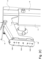
- a support mount 120 is provided on the supporting frame 10, namely at a distal end of the mast extension 12A, to secure the leg/knee support 50 onto the supporting frame. Part of this support mount 120 is visible on Figure 2 and Figure 2B . In the illustrated embodiment, upon being released, the leg/knee support 50 can be removed from the support mount 120 by sliding the leg/knee support 50 upward along the support mount 120, the support mount 120 acting as a guide.
- Figure 2C illustrates the support mount 120, without the leg/knee support 50 connected thereto.
- Figure 3A is an enlarged partial side view of a cross-section of the telescopic arm 180 of the patient lift apparatus 1 of Figure 1 showing a particularly preferred embodiment of the indexing mechanism 200.
- the indexing mechanism 200 comprises a releasable indexing plunger 210 mounted on the outer member 181 and having a retractable end portion 210A configured to engage with any selected positioning hole among a plurality of positioning holes 182A that are distributed longitudinally along a portion of the inner member 182.
- Figure 3A shows the retractable end portion 210A engaged with the second positioning hole 182A provided on the inner member 182 starting from the right. Eight positioning holes 182A are visible in Figure 3A , but it should be appreciated that any number of positioning holes 182A could be provided. The actual number of positioning holes 182A, and the distribution thereof along the length of the inner member 182, will be determined according to the needs, especially the desired overall amplitude of adjustment of the effective length of the telescopic arm 180 and the amplitude of each individual adjustment step.
- the indexing mechanism 200 further comprises a manually-operable release lever 250 that is mechanically linked to the releasable indexing plunger 210 to selectively allow retraction of the retractable end portion 210A of the indexing plunger 210 out of engagement with the selected positioning hole 182A, thereby releasing the inner member 182 and allowing repositioning thereof with respect to the outer member 181 at a different one of the predefined longitudinal positions.
- Figure 3B shows the retractable end portion 210A retracted out of engagement from the positioning hole 182A.
- one end 250A of the manually-operable release lever 250 is coupled to the releasable indexing plunger 210 and an intermediate portion of the manually-operable release lever 250 is configured to act as a pivot 250B about which the manually-operable lever 250 can pivot, upon being manually operated, as illustrated by Figures 3A-B , to cause retraction of the retractable end portion 210A of the indexing plunger 210.
- the relevant pivot axis of the manually-operable lever 250 is shown in Figures 3A-B and designated by reference sign PA2.
- the indexing mechanism 200 is located on a lower portion of the outer member 181.
- the release lever 250 is pivotably supported onto the same mounting bracket 185 as the upper end 15A of the boom actuator 15, which leads to a particularly simple and elegant integration of the indexing mechanism 200.
- the releasable indexing plunger 210 is preferably a spring-loaded indexing plunger whose retractable end portion 210A is configured to be urged towards an inner side of the outer member 181 and to automatically engage with any one of the plurality of positioning holes 182A provided on the inner member 182 upon alignment therewith.
- disengagement of the retractable end portion 210A of the releasable indexing plunger 210 is caused by a slight pivoting movement of the release lever 250 about the pivot axis PA2, namely in a counter-clockwise direction in the illustration of Figures 3A-B (as schematically illustrated by the curved arrow), i.e. by pressing the free end of the release lever 250 upward towards the outer member 181.
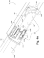
- Figure 4A is an enlarged partial perspective view of a section of the telescopic arm 180 of the patient lift apparatus 1 of Figure 1 showing a particularly preferred embodiment of the centering system 300.
- This centering system 300 is also visible in Figures 3A-B . Part of the outer member 181 has been omitted in the illustration of Figure 4A for the purpose of explanation.
- the centering system 300 includes a first centering element, designated by reference numeral 310, mounted on the outer member 181 and interposed between an inner side 181A of the outer member 181 and an outer periphery 182B of the inner member 182.
- the centering system 300 further comprises a second centering element, designated by reference numeral 320, mounted on the inner member 182 and guided inside the outer member 181.
- the first centering element is configured as a bushing member 310 mounted on a distal end portion of the outer member 181.
- a portion 310A, 310B of this bushing member 310 extends between the inner side 181A of the outer member 181 and the outer periphery 182B of the inner member 182, as this is visible in Figure 4A .
- Figure 4B shows the bushing member 310 with the outer member 181 being entirely omitted for the purpose of explanation.
- the second centering element is configured as a guiding member 320 mounted on a distal end portion of the inner member 182 and guided inside the outer member 181, as likewise shown in Figure 4A .
- Guide surfaces 320A are provided on the periphery of the guide member 320 for guidance against the inner side 181A of the outer member 181.
- the bushing member 310 comprises a plurality of extensions 310A extending longitudinally between the inner side 181A of the outer member 181 and the outer periphery 182B of the inner member 182 and a plurality of flat spring elements 315 located on said extensions 310A.
- a total of eight such extensions 310A and flat spring elements 315 are provided in the illustrated example, disposed in pairs along each of four sides, but it should be appreciated that any number of extensions and spring elements, and geometry, could be contemplated.
- the flat spring elements 315 are interposed between the inner side 181A of the outer member 181 and the extensions 310A to press these extensions 310A inwardly towards the outer periphery of the inner member 182 (see also Figures 3A-B ), thereby suppressing any play between the outer and inner members 181, 182
- Reference sign 310B in Figures 4A-B designates a further extension provided on each lateral side of the bushing member 310 to secure the bushing member 310 to the distal end of the outer member 181.
- This extension 310B is provided with a locking tab designed to engage with a corresponding mounting aperture provided on the outer member 181 (which mounting aperture is visible on Figures 1 , 2 and 2A ).
- the centering system 300 which is mounted on the outer member 181 and the inner member 182, is configured such as not to interfere with operation of the releasable indexing plunger 210 of the aforementioned indexing mechanism 200.
- the aforementioned solution to suppress the clearance between the outer and inner members 181, 182 of the telescopic arm 180 is particularly simple and robust.
- Other solutions could however be contemplated to reduce or suppress the clearance between the outer and inner members 181, 182, including solutions making use of e.g. an adjustable mechanism or an articulated linkage mounted on the inner member 182 and configured to translate a longitudinal displacement of a movable adjustment member into a radial displacement of two or more centering elements cooperating with the inner side 181A of the outer member 181.
- centering of the inner member 182 with respect to the outer member 181 could also be performed by means of a radially-adjustable mandrel device mounted within the inner member 182 and projecting through the inner member 182 toward the inner side 181A of the outer member 181.
- the leg/knee support 50 is configured to be selectively releasable from the supporting frame 10.
- the leg/knee support 50 advantageously comprises a manually-operable release mechanism forming an integral part of the leg/knee support 50, which manually-operable release mechanism is configured to allow selective release of the leg/knee support 50 from the supporting frame 10.
- This manually-operable release mechanism comprises a retaining device 51 configured to cooperate with the support mount 120 provided on the supporting frame 10, namely at a distal end of the mast extension 12A, as again illustrated in Figures 6A-B .
- the manually-operable release mechanism further comprises a manually-operable handle 55 that cooperates with the retaining device 51 to allow selective release of the retaining device 51 from the support mount 120 and thereby allow removal of the leg/knee support 50 from the supporting frame 10.
- the retaining device 51 may in particular comprise first and second retaining members 51A, 51B forming a spacing therebetween and which are configured to act as a guide dimensioned to receive the support mount 120 (see also Figures 2C and 6A-B ). More specifically, the first and second retaining members 51A, 51B are designed in such a way that the leg/knee support 50 can be slid onto the support mount 120, engagement and disengagement of the leg/knee support 50 occurring in the illustrated embodiment along a substantially vertical direction.
- Translation of the movement of the manually-operable handle 55 into a release action of the retaining device 51 can be carried out in different ways.
- One solution may consist in connecting the handle directly to the relevant retaining device or via an articulated linkage.
- a particularly simple and robust solution may consist, as illustrated in Figure 5 , in coupling the handle 55 to the retaining device 51 via a cable 52.
- reference sign 52A designates guide elements guiding the cable 52 from the handle 55 to the retaining device 51.
- This solution is particularly simple and provides great freedom for translating the movement of the handle 55 into the required release action of the retaining device 51.
- movement of the handle 55 and the release action of the retaining device 51 both occur as translational movements, however along different directions.
- the retaining device 51 comprises a releasable indexing plunger 510 having a retractable end portion 510A configured to engage with at least one positioning hole 120A provided on the support mount 120.
- the releasable indexing plunger 510 is mounted on the first retaining member 51A and the retractable end portion 510A extends through the spacing formed between the first and second retaining members 51A, 51B towards the second retaining member 51B.
- the releasable indexing plunger 510 is mechanically coupled to an end of the cable 52 to cause retraction of the retractable end portion 510 upon actuation of the handle 55.
- the releasable indexing plunger 510 is preferably a spring-loaded indexing plunger whose retractable end portion 510A is configured to be urged towards the support mount 120 and to automatically engage with any one of the positioning holes 120A provided on the support mount 120 upon alignment therewith.
- the aforementioned manually-operable release mechanism provides a simple and robust solution ensuring that the leg/knee support 50 is adequately secured to the supporting frame 10, while allowing easy and quick removal of the leg/knee support 50, without this requiring any tool.
- the leg/knee support 50 is configured to be partly pivotable with respect to the support mount 120 about a pivot axis, identified in Figures 5 and 6A-B by reference sign PA3, and within a defined pivoting range. More specifically, the outer casing 500 is configured to be pivotable with respect to the retaining device 51 about the pivot axis PA3 and within said defined pivoting range.
- At least one spring element 511, 512 coupling the outer casing 500 to the retaining device 51 is provided, which at least one spring element 511, 512 is configured to bring the outer casing 500 to a default position with respect to the retaining device 51 when no external force is applied onto the outer casing 500.
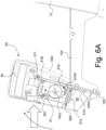
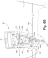
- a pair of spring elements 511, 512 is provided, which pair of spring elements 511, 512 is configured to bring the outer casing 500 to the default position, which default position is a median position between two extreme tilted positions. Such two extreme tilted positions are illustrated in Figure 6A and Figure 6B ..
- each spring element 511, 512 is a tension spring, namely a spring that stretches as load is applied to it.
- One end of each spring element 511, 512 is attached to a corresponding location of the retaining device 51 and the other end of each spring element 511, 512 is attached to a corresponding spring mount 501, respectively 502, provided on the outer casing 500.
- the first and second spring elements 511, 512 are disposed essentially symmetrically about the pivot axis PA3, meaning that one or the other spring element 511, 512 will stretch as the outer casing 500 pivots about the pivot axis PA3.
- FIG. 6A which shows the leg/knee support 50 in a first extreme tilted position where the outer casing 500 is pivoted in the clockwise direction about pivot axis PA3
- pivotal movement of the outer casing 500 causes an extension of the second (lower) spring element 512 compared to the default position illustrated in Figure 5 .
- the first (upper) spring element 511 is relieved from any tension.
- the first (upper) spring mount 501 comes in abutment with a corresponding section of the retaining device 51, preventing further pivotal movement of the outer casing 500 in the clockwise direction.
- the second spring element 512 will automatically pull the outer casing 500 to pivot in the counter-clockwise direction and return to the default position.
- FIG. 6B which shows the leg/knee support 50 in a second extreme tilted position where the outer casing 500 is pivoted in the counter-clockwise direction about pivot axis PA3
- pivotal movement of the outer casing 500 conversely causes an extension of the first (upper) spring element 511 compared to the default position illustrated in Figure 5 .
- the second (lower) spring element 512 is relieved from any tension in this case.
- the second (lower) spring mount 502 comes in abutment with a corresponding section of the retaining device 51, preventing further pivotal movement of the outer casing 500 in the counter-clockwise direction.
- the first spring element 511 will likewise automatically pull the outer casing 500 to pivot in the clockwise direction and return to the default position.
- each spring mount 501, 502 further acts as stop element limiting pivotal movement of the outer casing 500 about the pivot axis PA3.
- the leg/knee support 50 is configured so that a total amplitude of pivoting movement thereof with respect to the support mount 120 is of the order of 10 to 30 degrees.
- the leg/knee support 50 shown in Figures 5 and 6A-B is here configured to have a pivoting range of the order of +/- 8 degrees about de default position, i.e. a total amplitude of pivoting movement of the order of 16 degrees.
- the aforementioned solution allowing pivotal movement of the outer casing 500 with respect to the retaining device 51 is of great advantage to improve comfort for the patient during transfer from a seated position to a standing position, and vice versa, as the outer casing 500 will follow the actual and natural movement of the patient's legs and knees during the assisted transfer.
- the proposed solution is fully integrated and is not made to detriment of the operation of the aforementioned manually-operable release mechanism. In other words, both functions can be implemented, without this leading to a complex arrangement.
Landscapes
- Health & Medical Sciences (AREA)
- Nursing (AREA)
- Life Sciences & Earth Sciences (AREA)
- Animal Behavior & Ethology (AREA)
- General Health & Medical Sciences (AREA)
- Public Health (AREA)
- Veterinary Medicine (AREA)
- Orthopedics, Nursing, And Contraception (AREA)
- Accommodation For Nursing Or Treatment Tables (AREA)
- Invalid Beds And Related Equipment (AREA)
Claims (7)
- Eine Patientenliftvorrichtung (1), umfassend einen Trägerrahmen (10), einen Auslegerabschnitt (18), der mit dem Trägerrahmen (10) über ein Drehgelenk (PJ1) verbunden ist, um es dem Auslegerabschnitt (18) zu ermöglichen, in Bezug auf den Trägerrahmen (10) um eine Schwenkachse (PA1) herum zu schwenken, einen Auslegerstellantrieb (15), um eine Schwenkbewegung des Auslegerabschnitts (18) in Bezug auf den Trägerrahmen (10) mechanisch zu unterstützen, und eine Bein-/Kniestützung (50), der mit dem Trägerrahmen (10) verbunden ist,
dadurch gekennzeichnet, dass die Bein-/Kniestützung (50) umfasst:- eine Haltevorrichtung (51), die konfiguriert ist, um mit einer Trägerhalterung (120) zusammenzuwirken, die an dem Trägerrahmen (10) bereitgestellt ist, um die Bein-/Kniestützung (50) auf dem Trägerrahmen (10) zu befestigen, wobei die Bein-/Kniestützung (50) konfiguriert ist, um in Bezug auf die Trägerhalterung (120) um eine Schwenkachse (PA3) und innerhalb eines definierten Schwenkbereichs teilweise schwenkbar zu sein;- ein Außengehäuse (500), das konfiguriert ist, um in Bezug auf die Haltevorrichtung (51) um die Schwenkachse (PA3) und innerhalb des definierten Schwenkbereichs schwenkbar zu sein; und- mindestens ein Federelement (511, 512), das das Außengehäuse (500) mit der Haltevorrichtung (51) koppelt, wobei das mindestens eine Federelement (511, 512) konfiguriert ist, um das Außengehäuse (500) in eine Standardposition in Bezug auf die Haltevorrichtung (51) zu bringen, wenn keine äußere Kraft auf das Außengehäuse (500) ausgeübt wird. - Die Patientenliftvorrichtung (1) nach Anspruch 1, wobei ein Paar der Federelemente (511, 512) bereitgestellt ist, wobei das Paar der Federelemente (511, 512) konfiguriert ist, um das Außengehäuse (500) in die Standardposition zu bringen, wobei die Standardposition eine mittlere Position zwischen zwei äußersten geneigten Positionen ist,
wobei jedes Federelement (511, 512) an einer entsprechenden Federhalterung (501, 502) angebracht ist, die an dem Außengehäuse (500) bereitgestellt ist. - Die Patientenliftvorrichtung (1) nach Anspruch 2, wobei die Federhalterung (501, 502) ferner als Anschlagelement dient, das eine Schwenkbewegung des Außengehäuses (500) um die Schwenkachse (PA3) herum begrenzt.
- Die Patientenliftvorrichtung (1) nach einem der vorstehenden Ansprüche, wobei jedes Federelement (511, 512) eine Zugfeder ist.
- Die Patientenliftvorrichtung (1) nach einem der vorstehenden Ansprüche, wobei eine Gesamtamplitude der Schwenkbewegung der Bein-/Kniestützung (50) in Bezug auf die Trägerhalterung (120) in der Größenordnung von 10 bis 30 Grad liegt.
- Die Patientenliftvorrichtung (1) nach einem der vorstehenden Ansprüche, wobei der Auslegerabschnitt (18) als ein Teleskoparm (180) konfiguriert ist, umfassend ein Außenelement (181) und ein Innenelement (182), das im Inneren des Außenelements (181) teleskopisch aufgenommen ist, um eine Verschiebung des Innenelements (182) in Bezug auf das Außenelement (181) und die Einstellung einer wirksamen Länge des Teleskoparms (180) zu ermöglichen.
- Die Patientenliftvorrichtung (1) nach Anspruch 6, wobei die Patientenliftvorrichtung ferner einen Indexierungsmechanismus (200) umfasst, der dazu konfiguriert ist, eine Positionierung des Innenelements (182) an einer Vielzahl von vordefinierten Längspositionen in Bezug auf das Außenelement (181) zu ermöglichen.
Applications Claiming Priority (4)
| Application Number | Priority Date | Filing Date | Title |
|---|---|---|---|
| EP19155846.9A EP3692967A1 (de) | 2019-02-06 | 2019-02-06 | Patientenliftvorrichtung |
| EP19155847.7A EP3692968A1 (de) | 2019-02-06 | 2019-02-06 | Patientenliftvorrichtung |
| EP20703551.0A EP3920865B1 (de) | 2019-02-06 | 2020-02-03 | Patientenliftvorrichtung |
| PCT/IB2020/050836 WO2020161594A1 (en) | 2019-02-06 | 2020-02-03 | Patient lift apparatus |
Related Parent Applications (2)
| Application Number | Title | Priority Date | Filing Date |
|---|---|---|---|
| EP20703551.0A Division EP3920865B1 (de) | 2019-02-06 | 2020-02-03 | Patientenliftvorrichtung |
| EP20703551.0A Division-Into EP3920865B1 (de) | 2019-02-06 | 2020-02-03 | Patientenliftvorrichtung |
Publications (3)
| Publication Number | Publication Date |
|---|---|
| EP4233824A2 EP4233824A2 (de) | 2023-08-30 |
| EP4233824A3 EP4233824A3 (de) | 2023-09-06 |
| EP4233824B1 true EP4233824B1 (de) | 2025-01-29 |
Family
ID=69467616
Family Applications (3)
| Application Number | Title | Priority Date | Filing Date |
|---|---|---|---|
| EP20703550.2A Withdrawn EP3920864A1 (de) | 2019-02-06 | 2020-02-03 | Patientenhebevorrichtung |
| EP20703551.0A Active EP3920865B1 (de) | 2019-02-06 | 2020-02-03 | Patientenliftvorrichtung |
| EP23179097.3A Active EP4233824B1 (de) | 2019-02-06 | 2020-02-03 | Patientenliftvorrichtung |
Family Applications Before (2)
| Application Number | Title | Priority Date | Filing Date |
|---|---|---|---|
| EP20703550.2A Withdrawn EP3920864A1 (de) | 2019-02-06 | 2020-02-03 | Patientenhebevorrichtung |
| EP20703551.0A Active EP3920865B1 (de) | 2019-02-06 | 2020-02-03 | Patientenliftvorrichtung |
Country Status (6)
| Country | Link |
|---|---|
| US (2) | US20220133569A1 (de) |
| EP (3) | EP3920864A1 (de) |
| AU (3) | AU2020217901A1 (de) |
| CA (2) | CA3129279A1 (de) |
| NZ (1) | NZ779748A (de) |
| WO (2) | WO2020161594A1 (de) |
Families Citing this family (2)
| Publication number | Priority date | Publication date | Assignee | Title |
|---|---|---|---|---|
| US20230256282A1 (en) * | 2022-02-16 | 2023-08-17 | Omar Santos | Parallel Bar Stand Assistance Device |
| SE547213C2 (en) * | 2023-07-12 | 2025-06-03 | Arjo Ip Holding Ab | Releasable leg support for a flexible leg supporting membrane for supporting against lateral movement of a knee or lower leg resting against the flexible leg supporting membrane |
Family Cites Families (32)
| Publication number | Priority date | Publication date | Assignee | Title |
|---|---|---|---|---|
| US2846091A (en) | 1956-09-28 | 1958-08-05 | Ruth R Heffner | Invalid handling apparatus for vehicles |
| US3059785A (en) * | 1961-03-03 | 1962-10-23 | Kazmere S Buckeye | Crane or jack |
| JPS5332548A (en) * | 1976-09-04 | 1978-03-27 | Nippon Guroobu Kk | Extendable boom reaction support mechanism |
| JPS5335248A (en) | 1976-09-13 | 1978-04-01 | Matsushita Electric Ind Co Ltd | Treatment device for drainage containing heavy metals |
| US4349195A (en) * | 1979-05-15 | 1982-09-14 | Malcolm Johnston | Standing support for handicapped persons |
| US5076448A (en) | 1988-12-08 | 1991-12-31 | Hein-Werner Corporation | Portable hydraulic crane |
| US5054852A (en) * | 1989-08-30 | 1991-10-08 | Tholkes Alan L | Utility station with controlled seating |
| US5489258A (en) * | 1993-05-14 | 1996-02-06 | Bissell Inc. | Multi-position body support |
| US5459891A (en) * | 1993-08-24 | 1995-10-24 | Reeve; Richard J. | Invalid lift and transport apparatus |
| US5459841A (en) | 1993-12-28 | 1995-10-17 | At&T Corp. | Finite state machine with minimized vector processing |
| EP0739194B1 (de) | 1994-01-11 | 2000-07-05 | InterCare Scandinavia A/S | Hebevorrichtung zum bewegen von patienten sowie fusstützplatte zum gebrauch bei einer solchen hebevorrichtung |
| AU3673295A (en) | 1994-10-14 | 1996-05-06 | Ikeda Mohando Co., Ltd. | Posture change system and posture change method |
| US5758371A (en) | 1995-05-18 | 1998-06-02 | Vandyke; John Paul | Self-propelled independent mechanical handling device |
| JP3816173B2 (ja) | 1997-01-10 | 2006-08-30 | 株式会社日本製鋼所 | 介助支援トランスファ装置 |
| US5897101A (en) | 1997-03-13 | 1999-04-27 | Snyder; Ronald Jay | Collapsible engine hoist |
| GB9902466D0 (en) * | 1999-02-05 | 1999-03-24 | Arjo Ltd | An invalid lifting device |
| NL1012559C2 (nl) | 1999-07-09 | 2001-01-19 | Tilcentrum B V T | Tilinrichting. |
| DE20014830U1 (de) | 2000-08-26 | 2000-12-28 | Kranz, Norbert, 34549 Edertal | Zusammenlegbare Hubeinrichtung für Körperbehinderte |
| GB2391536B (en) * | 2002-08-09 | 2004-07-21 | Proto Magic Innovations Ltd | Patient raising device |
| DE20303002U1 (de) * | 2003-02-25 | 2003-06-26 | Sander, Wolfgang, 63679 Schotten | Mobiler Patienten-Aufricht- und Umsetzlift |
| NL1024909C2 (nl) * | 2003-12-01 | 2005-06-02 | Indes Holding Bv | Inrichting en werkwijze voor het verplaatsen van personen van een zittende naar een staande positie. |
| US7921485B2 (en) * | 2007-12-27 | 2011-04-12 | Joerns Healthcare, Llc | Folding patient lift device |
| NL2001474C2 (nl) * | 2008-04-11 | 2009-10-13 | Joyincare Group B V | Kleminrichting ten gebruike in een tillift voor het verplaatsen van personen. |
| CA2809275C (en) * | 2008-08-07 | 2014-11-25 | Invacare Corporation | Patient lift with adjustable knee pads and sling hooks |
| US20110016628A1 (en) | 2009-07-21 | 2011-01-27 | Masterson Jr Russell P | Portable apparatus for moving subjects |
| CH704421A2 (de) | 2011-01-25 | 2012-07-31 | Franco Rezzoli & Georg Zeller | Stehhilfe für Gehbehinderte. |
| DE102011006359B4 (de) * | 2011-03-29 | 2015-03-19 | MATIA ROBOTICS MEKATRONiK SiSTEMLER AR-GE MÜHENDiSLiK YAZILIM SANAYi VE TiCARET ANONiM SiRICETI | Mobilitätsvorrichtung für körperbehinderte Personen und Verfahren zum Aufrichten einer sitzenden körperbehinderten Person und zum Fixieren der Person im Stand auf einer selbstfahrenden Mobilitätsvorrichtung |
| DE202011100758U1 (de) | 2011-05-16 | 2011-09-05 | Leonair Gmbh | Patientenliftvorrichtung |
| ES2421058B1 (es) * | 2012-02-24 | 2014-09-10 | Crea & Ajuda, S.L. | Grúa de bipedestación para personas con condiciones de movilidad reducida. |
| DK178035B1 (en) * | 2013-03-26 | 2015-04-07 | Revac Aps | Apparatus and method for assisting impaired or disabled persons |
| IES20150100A2 (en) | 2014-04-09 | 2015-09-23 | Ardoo Caresafe Ltd | A hoist and stander apparatus |
| US11051906B2 (en) * | 2017-04-24 | 2021-07-06 | American Sterilizer Company | Ergonomic body positioning system |
-
2020
- 2020-02-03 AU AU2020217901A patent/AU2020217901A1/en not_active Abandoned
- 2020-02-03 NZ NZ779748A patent/NZ779748A/en unknown
- 2020-02-03 US US17/428,704 patent/US20220133569A1/en not_active Abandoned
- 2020-02-03 US US17/428,696 patent/US12076286B2/en active Active
- 2020-02-03 AU AU2020218862A patent/AU2020218862B2/en active Active
- 2020-02-03 EP EP20703550.2A patent/EP3920864A1/de not_active Withdrawn
- 2020-02-03 EP EP20703551.0A patent/EP3920865B1/de active Active
- 2020-02-03 CA CA3129279A patent/CA3129279A1/en active Pending
- 2020-02-03 WO PCT/IB2020/050836 patent/WO2020161594A1/en not_active Ceased
- 2020-02-03 EP EP23179097.3A patent/EP4233824B1/de active Active
- 2020-02-03 CA CA3129278A patent/CA3129278A1/en active Pending
- 2020-02-03 WO PCT/IB2020/050835 patent/WO2020161593A1/en not_active Ceased
-
2025
- 2025-10-09 AU AU2025248691A patent/AU2025248691A1/en active Pending
Also Published As
| Publication number | Publication date |
|---|---|
| EP4233824A3 (de) | 2023-09-06 |
| EP3920864A1 (de) | 2021-12-15 |
| AU2025248691A1 (en) | 2025-10-30 |
| AU2020218862B2 (en) | 2025-09-04 |
| EP3920865A1 (de) | 2021-12-15 |
| WO2020161594A1 (en) | 2020-08-13 |
| EP4233824A2 (de) | 2023-08-30 |
| NZ779748A (en) | 2026-03-27 |
| WO2020161593A1 (en) | 2020-08-13 |
| US20220133569A1 (en) | 2022-05-05 |
| US12076286B2 (en) | 2024-09-03 |
| CA3129278A1 (en) | 2020-08-13 |
| CA3129279A1 (en) | 2020-08-13 |
| US20220125654A1 (en) | 2022-04-28 |
| EP3920865B1 (de) | 2023-08-30 |
| AU2020217901A1 (en) | 2021-09-09 |
| AU2020218862A1 (en) | 2021-09-09 |
Similar Documents
| Publication | Publication Date | Title |
|---|---|---|
| US8650676B2 (en) | Patient lift and transfer device | |
| EP1685818B1 (de) | Entbindungstragvorrichtung | |
| US8650677B2 (en) | Hoist provided with a clamping device for moving persons | |
| US8336133B2 (en) | Multi-functional patient transfer device | |
| US20060016008A1 (en) | Stretcher with gear mechanism for adjustable height | |
| EP4233824B1 (de) | Patientenliftvorrichtung | |
| WO2015034372A1 (en) | Folding mechanism for a folding wheelchair, backrest post for wheelchair and wheelchair | |
| EP3692968A1 (de) | Patientenliftvorrichtung | |
| US20180168899A1 (en) | Patient bed with support assist | |
| EP3041448B1 (de) | Haltevorrichtung für eine rollstuhl-beinstütze und eine rückwärtswinkelvorrichtung für einen rollstuhl | |
| EP3692967A1 (de) | Patientenliftvorrichtung | |
| GB2617570A (en) | Intensive care chair | |
| CN105324099B (zh) | 用于滚入式担架床的辅助升降装置 | |
| JP4321851B2 (ja) | サドル着脱昇降式歩行車 | |
| CN216061040U (zh) | 移位装置 | |
| CN112587319A (zh) | 移位装置 | |
| EP3041447A1 (de) | Abnehmbare verbindungsstange eines rollstuhls und kippvorrichtung für den sitz eines rollstuhls |
Legal Events
| Date | Code | Title | Description |
|---|---|---|---|
| PUAI | Public reference made under article 153(3) epc to a published international application that has entered the european phase |
Free format text: ORIGINAL CODE: 0009012 |
|
| STAA | Information on the status of an ep patent application or granted ep patent |
Free format text: STATUS: THE APPLICATION HAS BEEN PUBLISHED |
|
| PUAL | Search report despatched |
Free format text: ORIGINAL CODE: 0009013 |
|
| AC | Divisional application: reference to earlier application |
Ref document number: 3920865 Country of ref document: EP Kind code of ref document: P |
|
| AK | Designated contracting states |
Kind code of ref document: A2 Designated state(s): AL AT BE BG CH CY CZ DE DK EE ES FI FR GB GR HR HU IE IS IT LI LT LU LV MC MK MT NL NO PL PT RO RS SE SI SK SM TR |
|
| AK | Designated contracting states |
Kind code of ref document: A3 Designated state(s): AL AT BE BG CH CY CZ DE DK EE ES FI FR GB GR HR HU IE IS IT LI LT LU LV MC MK MT NL NO PL PT RO RS SE SI SK SM TR |
|
| RIC1 | Information provided on ipc code assigned before grant |
Ipc: A61G 7/10 20060101AFI20230803BHEP |
|
| STAA | Information on the status of an ep patent application or granted ep patent |
Free format text: STATUS: REQUEST FOR EXAMINATION WAS MADE |
|
| 17P | Request for examination filed |
Effective date: 20240222 |
|
| RBV | Designated contracting states (corrected) |
Designated state(s): AL AT BE BG CH CY CZ DE DK EE ES FI FR GB GR HR HU IE IS IT LI LT LU LV MC MK MT NL NO PL PT RO RS SE SI SK SM TR |
|
| GRAP | Despatch of communication of intention to grant a patent |
Free format text: ORIGINAL CODE: EPIDOSNIGR1 |
|
| STAA | Information on the status of an ep patent application or granted ep patent |
Free format text: STATUS: GRANT OF PATENT IS INTENDED |
|
| INTG | Intention to grant announced |
Effective date: 20240823 |
|
| GRAS | Grant fee paid |
Free format text: ORIGINAL CODE: EPIDOSNIGR3 |
|
| GRAA | (expected) grant |
Free format text: ORIGINAL CODE: 0009210 |
|
| STAA | Information on the status of an ep patent application or granted ep patent |
Free format text: STATUS: THE PATENT HAS BEEN GRANTED |
|
| AC | Divisional application: reference to earlier application |
Ref document number: 3920865 Country of ref document: EP Kind code of ref document: P |
|
| AK | Designated contracting states |
Kind code of ref document: B1 Designated state(s): AL AT BE BG CH CY CZ DE DK EE ES FI FR GB GR HR HU IE IS IT LI LT LU LV MC MK MT NL NO PL PT RO RS SE SI SK SM TR |
|
| REG | Reference to a national code |
Ref country code: GB Ref legal event code: FG4D |
|
| REG | Reference to a national code |
Ref country code: CH Ref legal event code: EP |
|
| REG | Reference to a national code |
Ref country code: DE Ref legal event code: R096 Ref document number: 602020045711 Country of ref document: DE |
|
| REG | Reference to a national code |
Ref country code: IE Ref legal event code: FG4D |
|
| PGFP | Annual fee paid to national office [announced via postgrant information from national office to epo] |
Ref country code: CH Payment date: 20250301 Year of fee payment: 6 |
|
| REG | Reference to a national code |
Ref country code: NL Ref legal event code: MP Effective date: 20250129 |
|
| PG25 | Lapsed in a contracting state [announced via postgrant information from national office to epo] |
Ref country code: NL Free format text: LAPSE BECAUSE OF FAILURE TO SUBMIT A TRANSLATION OF THE DESCRIPTION OR TO PAY THE FEE WITHIN THE PRESCRIBED TIME-LIMIT Effective date: 20250129 |
|
| PG25 | Lapsed in a contracting state [announced via postgrant information from national office to epo] |
Ref country code: RS Free format text: LAPSE BECAUSE OF FAILURE TO SUBMIT A TRANSLATION OF THE DESCRIPTION OR TO PAY THE FEE WITHIN THE PRESCRIBED TIME-LIMIT Effective date: 20250429 |
|
| PG25 | Lapsed in a contracting state [announced via postgrant information from national office to epo] |
Ref country code: FI Free format text: LAPSE BECAUSE OF FAILURE TO SUBMIT A TRANSLATION OF THE DESCRIPTION OR TO PAY THE FEE WITHIN THE PRESCRIBED TIME-LIMIT Effective date: 20250129 |
|
| PG25 | Lapsed in a contracting state [announced via postgrant information from national office to epo] |
Ref country code: PL Free format text: LAPSE BECAUSE OF FAILURE TO SUBMIT A TRANSLATION OF THE DESCRIPTION OR TO PAY THE FEE WITHIN THE PRESCRIBED TIME-LIMIT Effective date: 20250129 |
|
| PG25 | Lapsed in a contracting state [announced via postgrant information from national office to epo] |
Ref country code: ES Free format text: LAPSE BECAUSE OF FAILURE TO SUBMIT A TRANSLATION OF THE DESCRIPTION OR TO PAY THE FEE WITHIN THE PRESCRIBED TIME-LIMIT Effective date: 20250129 |
|
| REG | Reference to a national code |
Ref country code: LT Ref legal event code: MG9D |
|
| PG25 | Lapsed in a contracting state [announced via postgrant information from national office to epo] |
Ref country code: IS Free format text: LAPSE BECAUSE OF FAILURE TO SUBMIT A TRANSLATION OF THE DESCRIPTION OR TO PAY THE FEE WITHIN THE PRESCRIBED TIME-LIMIT Effective date: 20250529 Ref country code: NO Free format text: LAPSE BECAUSE OF FAILURE TO SUBMIT A TRANSLATION OF THE DESCRIPTION OR TO PAY THE FEE WITHIN THE PRESCRIBED TIME-LIMIT Effective date: 20250429 |
|
| REG | Reference to a national code |
Ref country code: AT Ref legal event code: MK05 Ref document number: 1762762 Country of ref document: AT Kind code of ref document: T Effective date: 20250129 |
|
| PG25 | Lapsed in a contracting state [announced via postgrant information from national office to epo] |
Ref country code: HR Free format text: LAPSE BECAUSE OF FAILURE TO SUBMIT A TRANSLATION OF THE DESCRIPTION OR TO PAY THE FEE WITHIN THE PRESCRIBED TIME-LIMIT Effective date: 20250129 |
|
| PG25 | Lapsed in a contracting state [announced via postgrant information from national office to epo] |
Ref country code: PT Free format text: LAPSE BECAUSE OF FAILURE TO SUBMIT A TRANSLATION OF THE DESCRIPTION OR TO PAY THE FEE WITHIN THE PRESCRIBED TIME-LIMIT Effective date: 20250529 Ref country code: LV Free format text: LAPSE BECAUSE OF FAILURE TO SUBMIT A TRANSLATION OF THE DESCRIPTION OR TO PAY THE FEE WITHIN THE PRESCRIBED TIME-LIMIT Effective date: 20250129 |
|
| PG25 | Lapsed in a contracting state [announced via postgrant information from national office to epo] |
Ref country code: BG Free format text: LAPSE BECAUSE OF FAILURE TO SUBMIT A TRANSLATION OF THE DESCRIPTION OR TO PAY THE FEE WITHIN THE PRESCRIBED TIME-LIMIT Effective date: 20250129 Ref country code: GR Free format text: LAPSE BECAUSE OF FAILURE TO SUBMIT A TRANSLATION OF THE DESCRIPTION OR TO PAY THE FEE WITHIN THE PRESCRIBED TIME-LIMIT Effective date: 20250430 |
|
| PG25 | Lapsed in a contracting state [announced via postgrant information from national office to epo] |
Ref country code: AT Free format text: LAPSE BECAUSE OF FAILURE TO SUBMIT A TRANSLATION OF THE DESCRIPTION OR TO PAY THE FEE WITHIN THE PRESCRIBED TIME-LIMIT Effective date: 20250129 |
|
| PG25 | Lapsed in a contracting state [announced via postgrant information from national office to epo] |
Ref country code: SE Free format text: LAPSE BECAUSE OF FAILURE TO SUBMIT A TRANSLATION OF THE DESCRIPTION OR TO PAY THE FEE WITHIN THE PRESCRIBED TIME-LIMIT Effective date: 20250129 |
|
| PG25 | Lapsed in a contracting state [announced via postgrant information from national office to epo] |
Ref country code: SM Free format text: LAPSE BECAUSE OF FAILURE TO SUBMIT A TRANSLATION OF THE DESCRIPTION OR TO PAY THE FEE WITHIN THE PRESCRIBED TIME-LIMIT Effective date: 20250129 |
|
| PG25 | Lapsed in a contracting state [announced via postgrant information from national office to epo] |
Ref country code: DK Free format text: LAPSE BECAUSE OF FAILURE TO SUBMIT A TRANSLATION OF THE DESCRIPTION OR TO PAY THE FEE WITHIN THE PRESCRIBED TIME-LIMIT Effective date: 20250129 |
|
| PG25 | Lapsed in a contracting state [announced via postgrant information from national office to epo] |
Ref country code: MC Free format text: LAPSE BECAUSE OF FAILURE TO SUBMIT A TRANSLATION OF THE DESCRIPTION OR TO PAY THE FEE WITHIN THE PRESCRIBED TIME-LIMIT Effective date: 20250129 |
|
| PG25 | Lapsed in a contracting state [announced via postgrant information from national office to epo] |
Ref country code: LU Free format text: LAPSE BECAUSE OF NON-PAYMENT OF DUE FEES Effective date: 20250203 Ref country code: IT Free format text: LAPSE BECAUSE OF FAILURE TO SUBMIT A TRANSLATION OF THE DESCRIPTION OR TO PAY THE FEE WITHIN THE PRESCRIBED TIME-LIMIT Effective date: 20250129 |
|
| PG25 | Lapsed in a contracting state [announced via postgrant information from national office to epo] |
Ref country code: EE Free format text: LAPSE BECAUSE OF FAILURE TO SUBMIT A TRANSLATION OF THE DESCRIPTION OR TO PAY THE FEE WITHIN THE PRESCRIBED TIME-LIMIT Effective date: 20250129 Ref country code: CZ Free format text: LAPSE BECAUSE OF FAILURE TO SUBMIT A TRANSLATION OF THE DESCRIPTION OR TO PAY THE FEE WITHIN THE PRESCRIBED TIME-LIMIT Effective date: 20250129 |
|
| PG25 | Lapsed in a contracting state [announced via postgrant information from national office to epo] |
Ref country code: RO Free format text: LAPSE BECAUSE OF FAILURE TO SUBMIT A TRANSLATION OF THE DESCRIPTION OR TO PAY THE FEE WITHIN THE PRESCRIBED TIME-LIMIT Effective date: 20250129 |
|
| PG25 | Lapsed in a contracting state [announced via postgrant information from national office to epo] |
Ref country code: SK Free format text: LAPSE BECAUSE OF FAILURE TO SUBMIT A TRANSLATION OF THE DESCRIPTION OR TO PAY THE FEE WITHIN THE PRESCRIBED TIME-LIMIT Effective date: 20250129 |
|
| REG | Reference to a national code |
Ref country code: DE Ref legal event code: R097 Ref document number: 602020045711 Country of ref document: DE |
|
| PLBE | No opposition filed within time limit |
Free format text: ORIGINAL CODE: 0009261 |
|
| STAA | Information on the status of an ep patent application or granted ep patent |
Free format text: STATUS: NO OPPOSITION FILED WITHIN TIME LIMIT |
|
| REG | Reference to a national code |
Ref country code: BE Ref legal event code: MM Effective date: 20250228 |
|
| 26N | No opposition filed |
Effective date: 20251030 |
|
| PG25 | Lapsed in a contracting state [announced via postgrant information from national office to epo] |
Ref country code: BE Free format text: LAPSE BECAUSE OF NON-PAYMENT OF DUE FEES Effective date: 20250228 |
|
| PG25 | Lapsed in a contracting state [announced via postgrant information from national office to epo] |
Ref country code: IE Free format text: LAPSE BECAUSE OF NON-PAYMENT OF DUE FEES Effective date: 20250203 |
|
| PGFP | Annual fee paid to national office [announced via postgrant information from national office to epo] |
Ref country code: GB Payment date: 20260227 Year of fee payment: 7 |
|
| PGFP | Annual fee paid to national office [announced via postgrant information from national office to epo] |
Ref country code: DE Payment date: 20260227 Year of fee payment: 7 |
|
| PGFP | Annual fee paid to national office [announced via postgrant information from national office to epo] |
Ref country code: FR Payment date: 20260227 Year of fee payment: 7 |