EP4234093A2 - Pompe à fluide avec un sifflet - Google Patents
Pompe à fluide avec un sifflet Download PDFInfo
- Publication number
- EP4234093A2 EP4234093A2 EP23176739.3A EP23176739A EP4234093A2 EP 4234093 A2 EP4234093 A2 EP 4234093A2 EP 23176739 A EP23176739 A EP 23176739A EP 4234093 A2 EP4234093 A2 EP 4234093A2
- Authority
- EP
- European Patent Office
- Prior art keywords
- air
- sound
- fluid
- forming body
- air chamber
- Prior art date
- Legal status (The legal status is an assumption and is not a legal conclusion. Google has not performed a legal analysis and makes no representation as to the accuracy of the status listed.)
- Pending
Links
Images






















Classifications
-
- A—HUMAN NECESSITIES
- A47—FURNITURE; DOMESTIC ARTICLES OR APPLIANCES; COFFEE MILLS; SPICE MILLS; SUCTION CLEANERS IN GENERAL
- A47K—SANITARY EQUIPMENT; ACCESSORIES THEREFOR, e.g. TOILET ACCESSORIES
- A47K5/00—Holders or dispensers for soap, toothpaste or the like
- A47K5/06—Dispensers for soap
- A47K5/12—Dispensers for soap for liquid or pasty soap
- A47K5/1217—Electrical control means for the dispensing mechanism
-
- G—PHYSICS
- G08—SIGNALLING
- G08B—SIGNALLING SYSTEMS, e.g. PERSONAL CALLING SYSTEMS; ORDER TELEGRAPHS; ALARM SYSTEMS
- G08B3/00—Audible signalling systems, e.g. audible personal calling systems
- G08B3/06—Audible signalling systems, e.g. audible personal calling systems using hydraulic transmission; using pneumatic transmission
-
- A—HUMAN NECESSITIES
- A47—FURNITURE; DOMESTIC ARTICLES OR APPLIANCES; COFFEE MILLS; SPICE MILLS; SUCTION CLEANERS IN GENERAL
- A47K—SANITARY EQUIPMENT; ACCESSORIES THEREFOR, e.g. TOILET ACCESSORIES
- A47K5/00—Holders or dispensers for soap, toothpaste or the like
- A47K5/06—Dispensers for soap
- A47K5/12—Dispensers for soap for liquid or pasty soap
- A47K5/1202—Dispensers for soap for liquid or pasty soap dispensing dosed volume
- A47K5/1204—Dispensers for soap for liquid or pasty soap dispensing dosed volume by means of a rigid dispensing chamber and pistons
- A47K5/1207—Dispensing from the bottom of the dispenser with a vertical piston
-
- A—HUMAN NECESSITIES
- A47—FURNITURE; DOMESTIC ARTICLES OR APPLIANCES; COFFEE MILLS; SPICE MILLS; SUCTION CLEANERS IN GENERAL
- A47K—SANITARY EQUIPMENT; ACCESSORIES THEREFOR, e.g. TOILET ACCESSORIES
- A47K5/00—Holders or dispensers for soap, toothpaste or the like
- A47K5/14—Foam or lather making devices
-
- B—PERFORMING OPERATIONS; TRANSPORTING
- B05—SPRAYING OR ATOMISING IN GENERAL; APPLYING FLUENT MATERIALS TO SURFACES, IN GENERAL
- B05B—SPRAYING APPARATUS; ATOMISING APPARATUS; NOZZLES
- B05B1/00—Nozzles, spray heads or other outlets, with or without auxiliary devices such as valves, heating means
- B05B1/002—Nozzles, spray heads or other outlets, with or without auxiliary devices such as valves, heating means designed to reduce the generation or the transmission of noise or to produce a particular sound; associated with noise monitoring means
-
- B—PERFORMING OPERATIONS; TRANSPORTING
- B05—SPRAYING OR ATOMISING IN GENERAL; APPLYING FLUENT MATERIALS TO SURFACES, IN GENERAL
- B05B—SPRAYING APPARATUS; ATOMISING APPARATUS; NOZZLES
- B05B11/00—Single-unit hand-held apparatus in which flow of contents is produced by the muscular force of the operator at the moment of use
- B05B11/0005—Components or details
- B05B11/0059—Components or details allowing operation in any orientation, e.g. for discharge in inverted position
-
- B—PERFORMING OPERATIONS; TRANSPORTING
- B05—SPRAYING OR ATOMISING IN GENERAL; APPLYING FLUENT MATERIALS TO SURFACES, IN GENERAL
- B05B—SPRAYING APPARATUS; ATOMISING APPARATUS; NOZZLES
- B05B11/00—Single-unit hand-held apparatus in which flow of contents is produced by the muscular force of the operator at the moment of use
- B05B11/01—Single-unit hand-held apparatus in which flow of contents is produced by the muscular force of the operator at the moment of use characterised by the means producing the flow
- B05B11/10—Pump arrangements for transferring the contents from the container to a pump chamber by a sucking effect and forcing the contents out through the dispensing nozzle
- B05B11/1001—Piston pumps
-
- B—PERFORMING OPERATIONS; TRANSPORTING
- B05—SPRAYING OR ATOMISING IN GENERAL; APPLYING FLUENT MATERIALS TO SURFACES, IN GENERAL
- B05B—SPRAYING APPARATUS; ATOMISING APPARATUS; NOZZLES
- B05B11/00—Single-unit hand-held apparatus in which flow of contents is produced by the muscular force of the operator at the moment of use
- B05B11/01—Single-unit hand-held apparatus in which flow of contents is produced by the muscular force of the operator at the moment of use characterised by the means producing the flow
- B05B11/10—Pump arrangements for transferring the contents from the container to a pump chamber by a sucking effect and forcing the contents out through the dispensing nozzle
- B05B11/1087—Combination of liquid and air pumps
-
- F—MECHANICAL ENGINEERING; LIGHTING; HEATING; WEAPONS; BLASTING
- F04—POSITIVE - DISPLACEMENT MACHINES FOR LIQUIDS; PUMPS FOR LIQUIDS OR ELASTIC FLUIDS
- F04B—POSITIVE-DISPLACEMENT MACHINES FOR LIQUIDS; PUMPS
- F04B19/00—Machines or pumps having pertinent characteristics not provided for in, or of interest apart from, groups F04B1/00 - F04B17/00
-
- G—PHYSICS
- G01—MEASURING; TESTING
- G01F—MEASURING VOLUME, VOLUME FLOW, MASS FLOW OR LIQUID LEVEL; METERING BY VOLUME
- G01F11/00—Apparatus requiring external operation adapted at each repeated and identical operation to measure and separate a predetermined volume of fluid or fluent solid material from a supply or container, without regard to weight, and to deliver it
- G01F11/02—Apparatus requiring external operation adapted at each repeated and identical operation to measure and separate a predetermined volume of fluid or fluent solid material from a supply or container, without regard to weight, and to deliver it with measuring chambers which expand or contract during measurement
- G01F11/021—Apparatus requiring external operation adapted at each repeated and identical operation to measure and separate a predetermined volume of fluid or fluent solid material from a supply or container, without regard to weight, and to deliver it with measuring chambers which expand or contract during measurement of the piston type
-
- B—PERFORMING OPERATIONS; TRANSPORTING
- B05—SPRAYING OR ATOMISING IN GENERAL; APPLYING FLUENT MATERIALS TO SURFACES, IN GENERAL
- B05B—SPRAYING APPARATUS; ATOMISING APPARATUS; NOZZLES
- B05B11/00—Single-unit hand-held apparatus in which flow of contents is produced by the muscular force of the operator at the moment of use
- B05B11/01—Single-unit hand-held apparatus in which flow of contents is produced by the muscular force of the operator at the moment of use characterised by the means producing the flow
- B05B11/10—Pump arrangements for transferring the contents from the container to a pump chamber by a sucking effect and forcing the contents out through the dispensing nozzle
- B05B11/1042—Components or details
- B05B11/108—Means for counting the number of dispensing strokes
-
- F—MECHANICAL ENGINEERING; LIGHTING; HEATING; WEAPONS; BLASTING
- F04—POSITIVE - DISPLACEMENT MACHINES FOR LIQUIDS; PUMPS FOR LIQUIDS OR ELASTIC FLUIDS
- F04B—POSITIVE-DISPLACEMENT MACHINES FOR LIQUIDS; PUMPS
- F04B2201/00—Pump parameters
- F04B2201/02—Piston parameters
- F04B2201/0202—Linear speed of the piston
-
- F—MECHANICAL ENGINEERING; LIGHTING; HEATING; WEAPONS; BLASTING
- F04—POSITIVE - DISPLACEMENT MACHINES FOR LIQUIDS; PUMPS FOR LIQUIDS OR ELASTIC FLUIDS
- F04B—POSITIVE-DISPLACEMENT MACHINES FOR LIQUIDS; PUMPS
- F04B2201/00—Pump parameters
- F04B2201/02—Piston parameters
- F04B2201/0206—Length of piston stroke
-
- F—MECHANICAL ENGINEERING; LIGHTING; HEATING; WEAPONS; BLASTING
- F04—POSITIVE - DISPLACEMENT MACHINES FOR LIQUIDS; PUMPS FOR LIQUIDS OR ELASTIC FLUIDS
- F04B—POSITIVE-DISPLACEMENT MACHINES FOR LIQUIDS; PUMPS
- F04B23/00—Pumping installations or systems
- F04B23/02—Pumping installations or systems having reservoirs
-
- G—PHYSICS
- G01—MEASURING; TESTING
- G01F—MEASURING VOLUME, VOLUME FLOW, MASS FLOW OR LIQUID LEVEL; METERING BY VOLUME
- G01F13/00—Apparatus for measuring by volume and delivering fluids or fluent solid materials, not provided for in the preceding groups
Definitions
- the present invention is an improvement over the fluid dispenser and compliance monitoring system as disclosed in U.S. 8,816,860 .
- the improvements include providing at least two sounds in a cycle of operation by providing pressurized air to the same sound generator in temporally separated blasts and/or by providing two or more sound generators each to receive pressurized air in a cycle of operation.
- Producing at least two sounds also creates a richer sound profile, which can be used in at least some embodiments of the invention to calculate the dosage of fluid that was dispensed, and the distance and speed of movement of the actuator. This is useful for improving the detail and comprehensiveness of the compliance monitoring data, and may be useful for other purposes as well.
- the discharge of compressed air through the unsealed air passage reduces or eliminates the air flow through the air whistle during the first intermediate time period, resulting in distinct first and second sounds being produced by the air whistle during the first and second time periods, respectively, with little or no sound being produced in between.
- the air passage is optionally defined between the piston body and the air chamber forming body;
- the sound generator mechanism comprises an air whistle.
- the first sound generator produces the first sound during a first time period and the second sound generator produces the second sound during a second time period, the first time period being different than the second time period, the time period of each sound in the cycle of operation being a function of the relative location of the actuator between the first position and the second position.
- the first sound start position may, for example, be the first position
- the first sound end position may, for example, be the second position
- the second sound start position may, for example, be between the first position and the second position
- the second sound end position may, for example, be the second position.
- the actuator is configured to reduce a volume of air contained within the first air chamber forming body during movement from the first position to the second position, forcing at least some of the air to discharge from the first air chamber forming body through the first sound generator as the first stream of air;
- the outer edge of the piston body may be positioned within the unsealing zone when the piston body is between the first position and the second sound start position, and is positioned within the sealing zone when between the second sound start position and the second position.
- the actuator may, for example, comprise a piston body, wherein movement of the actuator from the first position to the second position comprises an instroke movement of the piston body within the air chamber forming body, thereby pressurizing the air contained within the air chamber forming body and forcing at least some of the air to discharge from the air chamber forming body.
- the third modular port may be configured to receive the third sound generator in both a forwards orientation and a backwards orientation
- the at least one air pump comprises an air chamber forming body in fluid communication with the first sound generator and the second sound generator; wherein the actuator is configured to increase a volume of air contained within the air chamber forming body during movement from the first position to the second position, drawing atmospheric air through the first sound generator as the first stream of air and through the second sound generator as the second stream of air.
- the fluid dispenser may further comprise a resistance generator configured to increase the pressure of the fluid contained within the fluid chamber to provide resistance against movement of the actuator from the first position to the second position, the actuator resisting movement from the first position to the second position as the pressure of the fluid contained within the fluid chamber increases.
- a resistance generator configured to increase the pressure of the fluid contained within the fluid chamber to provide resistance against movement of the actuator from the first position to the second position, the actuator resisting movement from the first position to the second position as the pressure of the fluid contained within the fluid chamber increases.
- the resistance generator may, for example, comprise a pressurizing valve that prevents the fluid from being expelled from the fluid outlet until the pressure within the fluid chamber exceeds a minimum fluid pressure.
- the resistance generator comprises a narrowing body that narrows a fluid pathway between the fluid chamber and the fluid outlet or at the fluid outlet.
- the narrowing body may comprise a plate with one or more apertures, the apertures being sized based on a predetermined fluid viscosity of the fluid, to provide resistance against a flow of the fluid through the apertures.
- the present invention resides in a fluid dispenser comprising:
- the actuator may, for example, comprises a piston body, wherein movement of the actuator from the first position to the second position comprises an instroke movement of the piston body within the air chamber; and wherein movement of the actuator from the second position to the first position comprises an outstroke movement of the piston body within the air chamber.
- the fluid pump optionally comprises the aforementioned fluid dispenser.
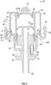
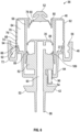
- the pressure within the fluid chamber 60 decreases. This creates a pressure differential between the fluid chamber 60 and the fluid reservoir 34, causing the relatively higher pressure fluid 26 within the reservoir 34 to push the inlet flange 78 of the inlet valve 52 downwards and inwards, allowing the fluid 26 to enter the fluid chamber 60 from the reservoir 34 through the opening 80. This fills the fluid chamber 60 with fluid 26, and thus readies the pump assembly 36 to dispense another allotment of fluid 26 when activated again.
- the air whistle 54 emits little or no sound.
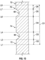
- the second time period as the sealing edge 92 moves along the second portion 74 of the inner surface 70 from location L4 to location L6, travelling distance D4, the air whistle 54 emits the second sound 30.
- the second intermediate time period as the sealing edge 92 moves axially adjacent to the second annular groove 68 from location L6 to location L7, travelling distance D5, the air whistle 54 again emits little or no sound.
- the pump assembly 36 may also be operated multiple times in a row, with incomplete outstroke movements in between. For example, after an initial complete instroke movement, the actuator panel 24 may not be fully released by the user, causing the second instroke movement to begin before the piston body 50 has had a chance to return to the extended first position shown in Figure 4 .
- the sealing edge 92 may, for example, only move from location L9 to location L4 during the incomplete outstroke movements. The subsequent instroke movements would thus only move from location L4 to location L9, causing the air whistle 54 to emit only the second 30 and third sounds 32, without emitting the first sound 28. Again, the amount of fluid 26 dispensed during these abbreviated instroke movements would be less than that dispensed during a complete instroke movement.
- the air pump 37 delivers both of the two streams of air through the sound generator mechanism 702 on movement of the actuator 700 in the cycle of operation in the first stroke.
- the sound generator mechanism 702 produces the two sounds 28, 30 as the actuator 700 is moved in the first stroke, with each sound 28, 30 produced in a different non-overlapping time period during the first stroke than the time period of the other sound 28, 30.
- the time period of each sound 28, 30 in the first stroke is a function of the relative location of the actuator 700 between the first position and the second position.
- the sound sensing mechanism 14 is spaced from the fluid dispenser 12 in a facility where the monitoring of hand cleaning activities is desired, such as a hospital, clinic, long term care facility, restaurant, or day care.
- the sound sensing mechanism 14 incorporates a sound sensor 15 that is configured to detect the first 28, second 30, and third sounds 32 emitted by the air whistle 54 when the fluid dispenser 12 is activated.
- the sound sensing mechanism 14 is communicatively linked to the remote computer 16, and is configured to transmit data representative of the detected sounds 28, 30, 32 to the computer 16.
- the sound sensing mechanism 14 is preferably wirelessly connected to the computer 16 via a Wi-Fi connection or the like, but could also use a wired connection.
- the computer 16 may be located within the same facility as the sound detecting mechanism 14, or could be located in a different area altogether and connected to the sound sensing mechanism 14 through the internet.
- the computer 16 is configured to analyze the detection data transmitted by the sound sensing mechanism 14 in order to distinguish detection data that represents an activation of the fluid dispenser 12 from detection data that represents other environmental sounds detected by the sound sensing mechanism 14.
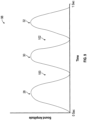
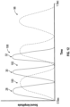
- activation of the fluid dispenser 12 produces a distinct sound profile 98, consisting of the first 28, second 30, and third sounds 32 temporally spaced from one another, with first 100 and second quiet periods 102 in between.
- This distinctive sound profile 98 is used by the computer 16 to distinguish activations of the fluid dispenser 12 from other sounds, such as the environmental sound profile 104 shown in Figure 10 .
- This sound profile 104 could be produced, for example, by a cough, a toilet flushing, or a door closing in the vicinity of the sound sensing mechanism 14.
- the computer 16 can also distinguish activations of the fluid dispenser 12 from environmental sounds when the dispenser 12 is operated with shortened or incomplete strokes, without requiring the precise sound profile 98 shown in Figure 9 .
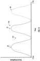
- a partial depression of the actuator panel 24 producing the modified sound profile 108 shown in Figure 11 , in which the third sound 32 is omitted could be distinguished from the environmental sound profile 104 shown in Figure 10 based on the presence of distinct first 28 and second sounds 30, with quiet period 100 there between.
- the computer 16 can be configured to recognize the modified sound profile 106, and to calculate or estimate various parameters based on the resulting detection data. For example, the number and timing of the detected sounds 28, 30, 32 can be used to estimate the movement distance of the piston body 50. This, in turn, can be used to estimate the volume of fluid 26 that was dispensed.
- the movement of the air displacement body 84 in an instroke movement at the faster speed may furthermore increase the pressure within the air chamber 64 compared to that when the actuator panel 24 is moved at the predetermined normal speed, thus delivering streams of air through the air whistle 54 at higher pressures.
- the computer 16 can be configured to recognize one or more of these effects in the detection data received from the sound sensing mechanism 14, and to calculate or estimate parameters such as the speed of the instroke movement or the pressure change within the air chamber 64 based thereon.
- the computer 16 is programmed to recognize different sound profiles 98, even when the sound profiles 98 are not uniform.
- the computer 16 may, for example, be programmed to recognize a set of predetermined threshold parameters that are found in a wide range of possible sound profiles 98 as indicating that the dispenser 12 has been activated, the parameters being selected to nonetheless distinguish activations of the dispenser 12 from other environmental sounds.
- the computer 16 may be programmed to recognize individual users and/or types of users based on their sound profiles 98. For example, individual users may operate the dispenser 12 in a unique and recognizable manner that produces a distinct sound profile 98.
- a first user might, for example, always dispense two allotments of fluid 26 using two complete instroke movements, pressing the actuator panel 24 at a uniform and moderate pace.
- a second user might always dispense five allotments of fluid 26 using five partial instroke movements at a rapid pace.
- These uses of the dispenser 12 will produce different sound profiles 98, which could be used to associate the compliance data with particular individuals.
- the data could also be used to generate general information about how the dispenser 12 is used, including information about the frequency of partial strokes, rapid strokes, slow strokes, and multiple strokes.
- the compliance monitoring system 10 would normally incorporate multiple fluid dispensers 12, multiple sound sensing mechanisms 14, and, in some embodiments, multiple computers 16.
- the system 10 could include, for example, a separate sound sensing mechanism 14 in each room of a monitored facility, each sound sensing mechanism 14 being positioned to detect the activation of multiple fluid dispensers 12 located nearby.
- the detection data from each sound sensing mechanism 14 could then be compiled by one or more computers 16 to produce compliance data representative of the entire facility.
- the data from the sound sensing mechanisms 14 could furthermore be combined with data from other compliance monitoring devices, such as hand cleaning devices that electronically record and transmit their own activation data.
- different fluid dispensers 12 could be configured to produce different sound profiles 98, so that the computer 16 could identify the specific fluid dispenser 12 that was activated based on the resulting detection data.
- the system 10 could include both manually operated and touchlessly operated dispensers 12, with the touchlessly operated dispensers 12 producing recognizable sound profiles 98 because of their uniform and predictable instroke speeds, and thus being distinguishable from the sound profiles 98 of the manually operated dispensers 12. Being able to identify the specific dispenser 12 that has been activated allows the computer 16 to produce more specific compliance data. This data may be used, for example, to help determine whether an infrequently used dispenser 12 should be relocated or more prominently displayed.
- the actuation flange 42 is movable relative to the piston body 50, and can be secured to the body 50 at different axial heights relative to the sealing edge 92.
- the actuation flange 42 could be provided as a separate movable element that is threaded to the lower end of the piston body 50, rather than being integrally formed therewith as shown.
- the actuation flange 42 could be provided with a central opening about the axis 59, with a radially inwardly facing surface of the opening having a helical thread that extends radially towards the axis 59 for engagement with a complementary thread formed on the outer surface of the piston body 50.
- the actuation flange 42 By turning the threaded actuation flange 42 in a clockwise or a counterclockwise direction about the axis 59, the actuation flange 42 could be displaced upwards or downwards relative to the piston body 50. The actuation flange 42 could then be locked in place at the selected axial height using a lock nut or the like.
- the location of the sealing edge 92 relative to the inner surface 70 of the outer wall 62 can be altered, thereby causing the dispenser 12 to produce a different sound profile 98 during activation.
- the edge 92 will sit at the higher location L2 when the piston body 50 is in the extended first position, rather than the lower location L1. This will cause the sealing edge 92 to move a reduced distance along the inner wall 70 during the instroke movement, from location L2 to location L9 instead of from location L1 to location L9.
- the dispensers 12 can be made to produce different sound profiles 98 when activated. This would allow the computer 16 to identify the specific dispenser 12 that has been activated, and thereby produce more specific compliance data as described above. Other modifications could be used to achieve much the same effect, such as by adjusting the support assembly 38 so that the movable seat 40 cycles through a different set of heights during the activation of different dispensers 12. Touchlessly operated dispensers 12 could also be configured to move the piston body 50 at different speeds, to produce uniquely identifiable sound profiles 98.
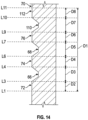
- the first annular groove 66 has been relocated axially outwards
- the second annular groove 68 has been relocated axially inwards.
- This configuration of the grooves 66, 68 shortens the distance D2 that the sealing edge 92 travels along the first portion 72 of the inner surface 70 when moving from location L1 to location L3 during the instroke movement. It also increases the distance D4 between location L4 and location L6, and decreases the distance D6 between location L7 and location L9.
- the shortened distance D2 causes the first sound 28 to have a shorter duration than in the first embodiment. Furthermore, since the sealing edge 92 reaches the first annular groove 66 earlier than in the first embodiment, the air within the air chamber 64 does not become as pressurized as in the first embodiment. This causes the first sound 28 to have a lower sound amplitude.
- the lengthened distance D4 likewise causes the second sound 30 to have a longer duration and a higher amplitude, while the shortened distance D6 causes the third sound 32 to have a shorter duration and a lower amplitude, in comparison with the first embodiment.
- a third annular groove 110 has been added, and the first 66 and second annular grooves 68 have been relocated axially outwards and positioned closer together.
- This configuration shortens the distances D2, D4, and D6, and further divides the inner surface 70 of the outer wall 62 into a fourth portion 112, located above the third annular groove 110.
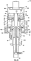
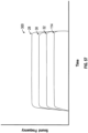
- the sealing edge 92 moves axially inwards and upwards along the inner surface 70 of the outer wall 62 from location L1 to location L11, producing the third sound profile 118 shown in Figure 17 .
- the pump assembly 36 produces the first 28, second 30, and third sounds 32, in a similar manner as in the first embodiment, with the shortened distances D2, D4, and D6 causing the first 28, second 30, and third sounds 32 to have a shortened duration and lower amplitude than in the first embodiment.
- the sealing edge 92 reaches and moves axially past the fourth annular groove 110 from location L9 to location L10, travelling distance D7, the air whistle 54 again emits little or no sound, producing the third quiet period 122 shown in Figure 17 .
- the air whistle 54 emits a fourth sound 114. Additional grooves could also be added to cause the pump assembly 36 to emit additional sounds.
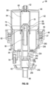
- the number of grooves could also be reduced, as in the fourth embodiment shown in Figure 15 .
- the second annular groove 68 has been removed, and the first annular groove 66 has been relocated axially inwards.
- This configuration lengthens the distances D2 and D4, and causes the pump assembly 36 to emit only the first 28 and second sounds 30, producing the fourth sound profile 120 shown in Figure 18 .
- the lengthened distances D2 and D4 cause the first 28 and second sounds 30 to have a longer duration and a higher amplitude than in the first embodiment.
- the piston chamber forming body 48 could be configured so that the air chamber 64 expands during the instroke movement and contracts during the outstroke movement. This could be achieved, for example, by defining the air chamber 64 axially outwards and downwards from the sealing edge 92, so that the instroke movement of the sealing edge 92 expands the air chamber 64 instead of compressing it.
- the air whistle 54 could also be configured to emit the first 28, second 30, and third sounds 32 while the air is moving into the air chamber 64 through the whistle 54, instead of while the air is being expelled. This could be achieved, for example, by reversing the orientation of an air whistle 54 that only produces sounds when air flows through the whistle 54 in a single direction, or by using an air whistle 54 that produces sounds when air flows through the whistle 54 in either direction.
- the line graph shown in Figure 9 depicts the instroke movement as having a duration of approximately one second, the invention is in no way limited to this duration. Different users may push the actuator panel 24 at significantly different speeds, causing the instroke movement to be much shorter or much longer than one second.
- the computer 16 is preferably configured to recognize a wide range of sound profiles 98 corresponding to different instroke speeds and durations, so as to produce accurate compliance data. In some embodiments of the invention, a typical duration of the instroke movement may be much longer or much shorter than 1 second.
- the fluid dispenser 12 is not limited to the specific construction that has been described and illustrated herein. Any fluid dispenser 12 that is operable to produce at least two sounds while dispensing fluid 26 could be used instead.
- the pump assembly 36 has been described and illustrated as having a construction similar to the pump disclosed in United States Patent No. 5,373,970 to Ophardt , other constructions such as those described in U.S. Patent No. 8,816,860 to Ophardt et al., issued August 26, 2014 ; U.S. Patent No. 8,976,031 to Ophardt, issued March 10, 2015 ; U.S. Patent Application Publication No. 2016/0097386 to Ophardt et al., published April 7, 2016 ; U.S. Patent Application Publication No.
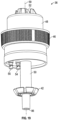
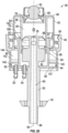
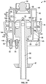
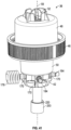
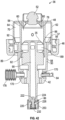
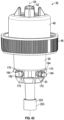
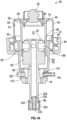
- FIG. 19 to 22 An example of an alternative construction is the fifth embodiment of the invention shown in Figures 19 to 22 , which provides a fluid pump 35 and two air pumps 37 and 137.
- the pump assembly 36 shown in Figures 19 to 22 is identical to the pump assembly 36 shown in Figure 4 , except for the following notable differences: the grooves 66, 68 are omitted; the outer wall 62 of the piston chamber forming body 48 has a lower section 144 that extends downwardly from the gripping collar 46; the piston body 50 includes both a first air displacement body 84 and a second air displacement body 85; and the piston body 50 uses two distinct air whistles 54 and 55 to produce the first 28 and second 30 sounds, respectively.
- Like numerals are used to identify like features.
- the piston body 50 has two air displacement bodies 84 and 85 for displacing the air within the first air chamber 64 and the second air chamber 65, respectively, and also respectively forming the first air pump 37 to draw and discharge air through the first air whistle 54 and the second air pump 137 to draw and discharge air through the second air whistle 55.
- the first air displacement body 84 extends upwards towards the upper section 140 of the outer wall 62 and has a first sealing edge 92 that is configured to sealingly engage with the inner surface 60 of the upper section 140.
- the second air displacement body 85 extends radially outwardly from the first air displacement body 84 towards the lower section 144 of the outer wall 62 and has a second sealing edge 93.
- the upwards movement of the fluid displacement body 82 within the fluid chamber 60 pressurizes the fluid 26 and forces the fluid 26 out through the fluid outlet 86.
- the upwards movement of the first air displacement body 84 within the first air chamber 64 also pressurizes the air within the first air chamber 64, thus delivering a first stream of pressurized air though the first air whistle 54, and causing the first air whistle 54 to emit the first sound 28.
- the first sealing edge 92 remains engaged with the inner surface 70 of the upper section 140 during the entire instroke movement.
- the first air whistle 54 therefore emits the first sound 28 during a first time period that spans the entire instroke movement, as the piston body 50 moves from the extended first position shown in Figure 20 to the retracted second position shown in Figure 22 .
- the pump assembly 36 can be used for dispensing fluid 26 from a housing 18 similar to the one shown in the first embodiment of the invention.
- the piston body 50 moves coaxially inwardly and upwards relative to the piston chamber forming body 48 in an instroke movement, as in the previously described embodiments.
- This moves the fluid displacement body 82 upwards and axially inwardly within the fluid chamber 60 and moves the air displacement body 84 upwards and axially inwardly within the air chamber 64.
- the upwards movement of the fluid displacement body 82 within the fluid chamber 60 pressurizes the fluid 26 and forces the fluid 26 out through the fluid outlet 86.
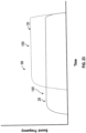
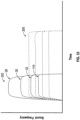
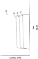
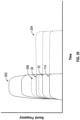
- the sounds 30, 32, 114 remain closer to the same frequencies even when the instroke movement is very rapid can be used to assist the computer 16 to recognize the sound profile 206 as an activation of the pump assembly 36. Since the air exits the air chamber 64 more rapidly during a rapid instroke, the sounds 30, 32, 114 have a shorter duration than in the sound profile 204 produced during a normal instroke.
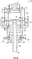
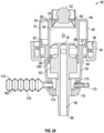
- the pressure relief valve 176 has been replaced by a modular air accumulating bellows 178.
- the bellows 178 has an accordion-like shape and is resiliently expandable from the contracted state shown in Figure 27 to the expanded state shown in Figure 28 .
- the bellows 178 define an internal air cavity 180 that is in fluid communication with the air chamber 64.
- the air cavity 180 has a larger volume in the expanded state than in the contracted state.
- the bellows 178 is resiliently biased towards the contracted state, and only expands towards the expanded state when the air pressure within the air chamber 64 exceeds a preselected threshold adequate to overcome the bias.
- the bellows 178 is configured to return to the contracted state, releasing the collected pressurized air back into the air chamber 64.
- the accumulation of pressurized air within the bellows 178 can assist in keeping the pressure within the air chamber 64 at or below the threshold pressure, and thus acts to moderate fluctuations in the frequencies of the sounds 30, 32, 114 produced by the air whistles 55, 172, 164 when the pump assembly 36 is activated at different velocities, similarly to the pressure relief valve 176. Furthermore, the return of the accumulated pressurized air from the bellows 178 to the air chamber 64 may help to moderate fluctuations in the durations of the sounds 30, 32, 114, since the pressurized air from the bellows 178 is forced out through the air whistles 55, 172, 174 at the end of the instroke rather than bypassing the whistles 55, 172, 174 as in the previous configuration.
- the bellows 178 is configured so that it expands minimally before the threshold pressure is reached, and expands rapidly once the threshold pressure is reached. This helps to keep the pressure within air chamber 64 at or below the threshold pressure, since the entire volume of the expanded bellows 178 is available to accumulate air displaced from the chamber 64 at or near the threshold pressure.
- the resistance of the bellows 178 to expansion may significantly increase as the bellows 178 expands, so that the fully expanded state is only reached at well above the threshold pressure.
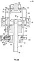
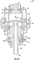
- the modular air whistles 54, 55, 172, 174 and the ports 170 are configured so that the whistles 54, 55, 172, 174 can be received within the ports 170 in the forwards orientation shown in Figures 24 to 28 , or alternatively, in the backwards orientation shown in Figure 29 .
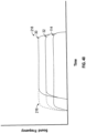
- the whistles 54, 55, 172, 174 produce the sounds 28, 30, 32, 114 as air is drawn from the atmosphere into the air chamber 64 through the whistles 54, 55, 172, 174, rather than when air is expelled from the air chamber 64 out through the whistles 54, 55, 172, 174.
- the air whistles 54, 55, 172, 174 each have an air channel 190 that delivers air to a sound generating portion 188.
- the configuration shown in Figure 29 produces the sound profile 212 shown in Figure 38 .
- the sound profile 212 is generally similar to that shown in Figure 34 , with the exception that the sounds 30, 32, 114 are produced during the outstroke movement rather than the instroke.
- the pump assembly 36 may be configured to draw air into the air chamber 64 through the whistles 55, 172, 174 to produce the sounds 30, 32, 114 during the instroke movement rather than the outstroke movement.
- the configuration shown in Figure 29 produces three sounds 30, 32, 114 instead of four because a plug 182 has been inserted into the remaining port 170.
- the plug 182 forces more air to pass through each whistle 55, 172, 174, in comparison with a configuration using four whistles 54, 55, 172, 174 instead of three, and thus helps to ensure that the air streams passing through the whistles 55, 172, 174 are forceful enough to generate the sounds 30, 32, 114.
- Plugs 182 can also be used to alter the sound profile 200 produced by the pump assembly 36 by removing one or more of the sounds 28, 30, 32, 114, and thus allow for an even greater variety of unique sound profiles 200 for the purpose of compliance monitoring.
- a very slow instroke movement may cause the air passing through the air whistles 54, 55, 172, 174 to pass through at a rate that is too slow to generate the sounds 28, 20, 32, 114.
- This problem becomes more severe as the number of air whistles 54, 55, 172, 174 increases, since each whistle 54, 55, 172, 174 expels a smaller share of the air displaced by the air displacement body 84 as the number of whistles 54, 55, 172, 174 increases.
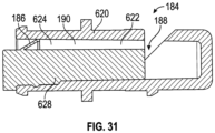
- the pressure opening air whistle 184 has a generally cylindrical whistle chamber forming body 620 defining an internal whistle chamber 622.
- the whistle chamber 622 has an air channel forming portion 624 that is open to the air chamber 64 and a sound generating portion 188 that is open to the atmosphere.
- An air channel narrowing body 628 is inserted into the air channel forming portion 624.
- the pressure opening valves 186 could be configured to open at different threshold pressures. This would cause the sounds 28, 30, 32, 114 to begin at different times during the instroke movement, when the whistles 184 are oriented forwardly, as the pressure within the air chamber 64 reaches and is maintained at or above each respective threshold pressure.
- a wide variety of sound profiles 200 could be produced for uniquely identifying different pump assemblies 36 and collecting more detailed compliance monitoring data.
- the sound profiles 200 could also be used to gather additional information about the operation of the pump assemblies 36, with the number and frequency of the sounds 28, 30, 32, 114 being used to determine the air pressure that was reached within the air chamber 64 during activation.
- the resistance generator 220 comprises a molded pressurizing valve 228 in place of the spring-loaded valve 222.
- This embodiment is otherwise identical to the previous embodiment (although different modular components are shown in the ports 170).
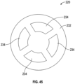
- the molded pressurizing valve 228 is fixed within the outlet channel 90 by being secured at its outer end in an inwardly extending central socket of the aperture plate 232.
- the valve 228 has an annular resiliently deformable pressurizing flange 230 that is angled axially downwards and radially outwards into fluid tight engagement with the annular inner surface of the outlet channel 90.
- the size of the apertures 234 may, for example, be selected to provide significant resistance against the flow of fluid 26 through the aperture plate 232 above a preselected threshold flow rate, while providing minimal resistance below that flow rate, with the preselected threshold flow rate corresponding to a preselected velocity of the piston body 50 during the instroke movement. This arrangement helps to keep the instroke movement at or below the preselected velocity, even when the actuator panel 24 is depressed forcefully, and thus leads to more consistent sound profiles 200 for compliance monitoring.
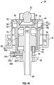
- a pump assembly 36 in accordance with a ninth embodiment of the invention is shown in Figure 46 .
- This embodiment is identical to the pump assembly 36 shown in Figure 27 , but lacks the modular ports 170 and incorporates only a single air whistle 54 in fluid communication with the air chamber 64.
- the pump assembly 36 is operated in an identical manner as the configuration shown in Figure 27 , with the bellows 178 expanding when the pressure within the air chamber 64 exceeds a preselected threshold, to moderate fluctuations in the sound 28 produced by the air whistle 54.
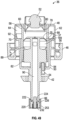
- the pump assembly 36 includes two air whistles 54, 55 that produce the first and second sounds 28, 30 simultaneously, with each air stream coming from a separate air chamber 64, 65.
- the first annular air chamber 64 is defined between the inner wall 58 and the outer wall 62 of the piston chamber forming body 48.
- the first air whistle 54 is positioned adjacent to the fluid displacement body 82, and is in fluid communication with the first air chamber 64.
Landscapes
- Health & Medical Sciences (AREA)
- Public Health (AREA)
- Physics & Mathematics (AREA)
- General Physics & Mathematics (AREA)
- Engineering & Computer Science (AREA)
- Fluid Mechanics (AREA)
- Mechanical Engineering (AREA)
- General Engineering & Computer Science (AREA)
- Containers And Packaging Bodies Having A Special Means To Remove Contents (AREA)
- Reciprocating Pumps (AREA)
Priority Applications (1)
| Application Number | Priority Date | Filing Date | Title |
|---|---|---|---|
| EP26160588.5A EP4725614A2 (fr) | 2018-04-04 | 2019-04-03 | Pompe à fluide avec sifflet |
Applications Claiming Priority (2)
| Application Number | Priority Date | Filing Date | Title |
|---|---|---|---|
| CA3000244A CA3000244A1 (fr) | 2018-04-04 | 2018-04-04 | Pompe de fluide equipee d'un sifflet |
| EP19167011.6A EP3549498B1 (fr) | 2018-04-04 | 2019-04-03 | Pompe à fluide avec un sifflet |
Related Parent Applications (2)
| Application Number | Title | Priority Date | Filing Date |
|---|---|---|---|
| EP19167011.6A Division-Into EP3549498B1 (fr) | 2018-04-04 | 2019-04-03 | Pompe à fluide avec un sifflet |
| EP19167011.6A Division EP3549498B1 (fr) | 2018-04-04 | 2019-04-03 | Pompe à fluide avec un sifflet |
Related Child Applications (1)
| Application Number | Title | Priority Date | Filing Date |
|---|---|---|---|
| EP26160588.5A Division EP4725614A2 (fr) | 2018-04-04 | 2019-04-03 | Pompe à fluide avec sifflet |
Publications (2)
| Publication Number | Publication Date |
|---|---|
| EP4234093A2 true EP4234093A2 (fr) | 2023-08-30 |
| EP4234093A3 EP4234093A3 (fr) | 2023-10-18 |
Family
ID=66092039
Family Applications (3)
| Application Number | Title | Priority Date | Filing Date |
|---|---|---|---|
| EP19167011.6A Active EP3549498B1 (fr) | 2018-04-04 | 2019-04-03 | Pompe à fluide avec un sifflet |
| EP26160588.5A Pending EP4725614A2 (fr) | 2018-04-04 | 2019-04-03 | Pompe à fluide avec sifflet |
| EP23176739.3A Pending EP4234093A3 (fr) | 2018-04-04 | 2019-04-03 | Pompe à fluide avec un sifflet |
Family Applications Before (2)
| Application Number | Title | Priority Date | Filing Date |
|---|---|---|---|
| EP19167011.6A Active EP3549498B1 (fr) | 2018-04-04 | 2019-04-03 | Pompe à fluide avec un sifflet |
| EP26160588.5A Pending EP4725614A2 (fr) | 2018-04-04 | 2019-04-03 | Pompe à fluide avec sifflet |
Country Status (3)
| Country | Link |
|---|---|
| US (3) | US11545011B2 (fr) |
| EP (3) | EP3549498B1 (fr) |
| CA (1) | CA3000244A1 (fr) |
Families Citing this family (6)
| Publication number | Priority date | Publication date | Assignee | Title |
|---|---|---|---|---|
| CN113287958A (zh) * | 2015-10-30 | 2021-08-24 | 金伯利-克拉克环球有限公司 | 产品使用情况声学确定系统 |
| EP3683188B1 (fr) | 2019-01-16 | 2023-12-13 | OP-Hygiene IP GmbH | Méthode de surveillance de la production d'ozone par un générateur d'ozone doté d'un capteur |
| US11084052B2 (en) * | 2019-12-31 | 2021-08-10 | Op-Hygiene Ip Gmbh | Stationary outlet stem pump |
| US20250018411A1 (en) * | 2021-11-19 | 2025-01-16 | Rieke Packaging Systems Limited | Single-polymer, reciprocating dispenser for foam products |
| CN118197323A (zh) * | 2022-11-04 | 2024-06-14 | 荣耀终端有限公司 | 一种语音交互方法及相关电子设备 |
| CA3275441A1 (en) * | 2024-06-06 | 2026-01-19 | Op-Hygiene Ip Gmbh | Foam Dispenser with Moveable Foam Generator |
Citations (11)
| Publication number | Priority date | Publication date | Assignee | Title |
|---|---|---|---|---|
| US5373970A (en) | 1993-10-29 | 1994-12-20 | Hygiene-Technik Inc. | Liquid soap dispenser for simplified replacement of soap reservoir |
| US5836482A (en) | 1997-04-04 | 1998-11-17 | Ophardt; Hermann | Automated fluid dispenser |
| US7267251B2 (en) | 2004-06-09 | 2007-09-11 | Hygiene-Technik Inc. | Draw back pump |
| US7984825B2 (en) | 2007-06-18 | 2011-07-26 | Gotohti.Com Inc. | Optically keyed dispenser |
| US8113388B2 (en) | 2008-12-08 | 2012-02-14 | Heiner Ophardt | Engagement flange for removable dispenser cartridge |
| US8684236B2 (en) | 2009-02-27 | 2014-04-01 | Gotohti.Com Inc. | Manual fluid dispenser with piezoelectric generator |
| US8816860B2 (en) | 2011-04-08 | 2014-08-26 | Gotohti.Com Inc. | Dispenser with sound generators |
| US8976031B2 (en) | 2011-04-08 | 2015-03-10 | Gotohti.Com Inc. | Personal compliance dispenser |
| US20150190827A1 (en) | 2014-01-06 | 2015-07-09 | Op-Hygiene Ip Gmbh | Dispenser Cover Retention Arrangement |
| US20160097386A1 (en) | 2014-10-03 | 2016-04-07 | Op-Hygiene Ip Gmbh | Displacement Pump |
| US20160256015A1 (en) | 2014-08-29 | 2016-09-08 | Op-Hygiene Ip Gmbh | Pump Assembly Carrying Rasp |
Family Cites Families (13)
| Publication number | Priority date | Publication date | Assignee | Title |
|---|---|---|---|---|
| US110547A (en) * | 1870-12-27 | Improvement in annunciators | ||
| US2199404A (en) * | 1937-10-13 | 1940-05-07 | Sperry Gyroscope Co Inc | Sound locator apparatus |
| US4674654A (en) | 1982-11-24 | 1987-06-23 | Mituru Fujii | Liquid dispenser having sound generating mechanism |
| CA1206442A (fr) | 1982-11-24 | 1986-06-24 | Mituru Fujii | Debiteur de liquide a dispositif sonore |
| US4798313A (en) * | 1987-07-27 | 1989-01-17 | Farley Brent L | Elastomeric bladder for dispensing ice cream |
| US5810201A (en) * | 1996-07-22 | 1998-09-22 | Ecolab Inc. | Interactive dispenser for personal use chemical or personal care chemical that provides a message prompted by user proximity |
| US6065639A (en) * | 1999-02-26 | 2000-05-23 | Gojo Industries, Inc. | Multiple use wash counter and timer |
| US20060249530A1 (en) * | 2005-05-06 | 2006-11-09 | Allure Home Creations Co., Inc. | Dispenser with sound and motion |
| US20090261123A1 (en) | 2007-07-30 | 2009-10-22 | International Product Solutions, Inc. | Pump assembly with sound emitting device |
| DK2478502T3 (en) | 2009-09-16 | 2016-08-29 | Nobak Danmark Aps | A system and method for motivating and / or encourage people to wash hands |
| CA2770704A1 (fr) | 2012-03-06 | 2013-09-06 | Heiner Ophardt | Distributeurs munis de generateurs de son |
| CN113287958A (zh) | 2015-10-30 | 2021-08-24 | 金伯利-克拉克环球有限公司 | 产品使用情况声学确定系统 |
| AU2017331740B2 (en) * | 2016-09-21 | 2023-03-30 | Smart Wave Technologies Inc. | Universal dispenser monitor |
-
2018
- 2018-04-04 CA CA3000244A patent/CA3000244A1/fr active Pending
-
2019
- 2019-04-03 US US16/373,899 patent/US11545011B2/en active Active
- 2019-04-03 EP EP19167011.6A patent/EP3549498B1/fr active Active
- 2019-04-03 EP EP26160588.5A patent/EP4725614A2/fr active Pending
- 2019-04-03 EP EP23176739.3A patent/EP4234093A3/fr active Pending
-
2022
- 2022-11-29 US US18/059,828 patent/US11954997B2/en active Active
-
2024
- 2024-03-01 US US18/593,250 patent/US12361800B2/en active Active
Patent Citations (11)
| Publication number | Priority date | Publication date | Assignee | Title |
|---|---|---|---|---|
| US5373970A (en) | 1993-10-29 | 1994-12-20 | Hygiene-Technik Inc. | Liquid soap dispenser for simplified replacement of soap reservoir |
| US5836482A (en) | 1997-04-04 | 1998-11-17 | Ophardt; Hermann | Automated fluid dispenser |
| US7267251B2 (en) | 2004-06-09 | 2007-09-11 | Hygiene-Technik Inc. | Draw back pump |
| US7984825B2 (en) | 2007-06-18 | 2011-07-26 | Gotohti.Com Inc. | Optically keyed dispenser |
| US8113388B2 (en) | 2008-12-08 | 2012-02-14 | Heiner Ophardt | Engagement flange for removable dispenser cartridge |
| US8684236B2 (en) | 2009-02-27 | 2014-04-01 | Gotohti.Com Inc. | Manual fluid dispenser with piezoelectric generator |
| US8816860B2 (en) | 2011-04-08 | 2014-08-26 | Gotohti.Com Inc. | Dispenser with sound generators |
| US8976031B2 (en) | 2011-04-08 | 2015-03-10 | Gotohti.Com Inc. | Personal compliance dispenser |
| US20150190827A1 (en) | 2014-01-06 | 2015-07-09 | Op-Hygiene Ip Gmbh | Dispenser Cover Retention Arrangement |
| US20160256015A1 (en) | 2014-08-29 | 2016-09-08 | Op-Hygiene Ip Gmbh | Pump Assembly Carrying Rasp |
| US20160097386A1 (en) | 2014-10-03 | 2016-04-07 | Op-Hygiene Ip Gmbh | Displacement Pump |
Also Published As
| Publication number | Publication date |
|---|---|
| EP3549498B1 (fr) | 2023-07-12 |
| US20240203218A1 (en) | 2024-06-20 |
| US11954997B2 (en) | 2024-04-09 |
| US20190311587A1 (en) | 2019-10-10 |
| US11545011B2 (en) | 2023-01-03 |
| EP3549498A1 (fr) | 2019-10-09 |
| CA3000244A1 (fr) | 2019-10-04 |
| EP4234093A3 (fr) | 2023-10-18 |
| US20230086466A1 (en) | 2023-03-23 |
| US12361800B2 (en) | 2025-07-15 |
| EP4725614A2 (fr) | 2026-04-15 |
Similar Documents
| Publication | Publication Date | Title |
|---|---|---|
| US11954997B2 (en) | Fluid pump with whistle | |
| US6540117B2 (en) | Dosing pump for liquid dispensers | |
| US8313308B2 (en) | Medical infusion pump with closed loop stroke feedback system and method | |
| JP5205645B2 (ja) | 改良された低流量医療用ポンプ吐出のためのシステムおよび方法 | |
| US20020074355A1 (en) | Dosing pump for liquid dispensers | |
| US4762475A (en) | Thrust piston pump for the discharge of media | |
| US9062667B2 (en) | Variable volume bore piston pump | |
| JP5828181B2 (ja) | 一回転で作動する持続性噴霧ポンプ機構 | |
| JPH08511988A (ja) | 伸縮自在のポンプチャンバを備えた、一体の輸送シールを持つポンプ装置 | |
| JPH11500661A (ja) | 作動力を低減した高圧手動スプレイポンプ | |
| EP0450267A2 (fr) | Distributeur à pompe à actionnement manuel pour usage pharmaceutique | |
| US4231493A (en) | Lever pump with button actuator | |
| EP3556472B1 (fr) | Pompe à mousse à deux étages et procédé de production de mousse | |
| MXPA05004073A (es) | Metodo para elegir entre condiciones de operacion en bomba medica. | |
| EP0867232A2 (fr) | Micropompe munie d'une valve doseuse pour la nébulisation de fluides | |
| US20070295756A1 (en) | Pump for Dispensing Fluid Products | |
| CN101534958B (zh) | 流体产品分配装置 | |
| NL2035602B1 (en) | Device and system for dispensing a liquid | |
| JP6421207B2 (ja) | 機械的に付勢された持続性噴霧機構による製品放出方法 | |
| JP2007000738A (ja) | ポンプディスペンサ | |
| AU2002235223A1 (en) | Dosing pump for liquid dispensers | |
| HK1206810B (en) | One turn actuated duration spray pump mechanism | |
| MXPA98004541A (en) | High pressure and manual drive spraying pump that requires reduced force of action. |
Legal Events
| Date | Code | Title | Description |
|---|---|---|---|
| PUAI | Public reference made under article 153(3) epc to a published international application that has entered the european phase |
Free format text: ORIGINAL CODE: 0009012 |
|
| STAA | Information on the status of an ep patent application or granted ep patent |
Free format text: STATUS: THE APPLICATION HAS BEEN PUBLISHED |
|
| AC | Divisional application: reference to earlier application |
Ref document number: 3549498 Country of ref document: EP Kind code of ref document: P |
|
| AK | Designated contracting states |
Kind code of ref document: A2 Designated state(s): AL AT BE BG CH CY CZ DE DK EE ES FI FR GB GR HR HU IE IS IT LI LT LU LV MC MK MT NL NO PL PT RO RS SE SI SK SM TR |
|
| REG | Reference to a national code |
Ref country code: DE Ref legal event code: R079 Free format text: PREVIOUS MAIN CLASS: B05B0001000000 Ipc: A47K0005120000 |
|
| PUAL | Search report despatched |
Free format text: ORIGINAL CODE: 0009013 |
|
| AK | Designated contracting states |
Kind code of ref document: A3 Designated state(s): AL AT BE BG CH CY CZ DE DK EE ES FI FR GB GR HR HU IE IS IT LI LT LU LV MC MK MT NL NO PL PT RO RS SE SI SK SM TR |
|
| RIC1 | Information provided on ipc code assigned before grant |
Ipc: B05B 1/00 20060101ALI20230912BHEP Ipc: G01F 11/02 20060101ALI20230912BHEP Ipc: B05B 11/00 20230101ALI20230912BHEP Ipc: A47K 5/14 20060101ALI20230912BHEP Ipc: A47K 5/12 20060101AFI20230912BHEP |
|
| STAA | Information on the status of an ep patent application or granted ep patent |
Free format text: STATUS: REQUEST FOR EXAMINATION WAS MADE |
|
| 17P | Request for examination filed |
Effective date: 20240327 |
|
| RBV | Designated contracting states (corrected) |
Designated state(s): AL AT BE BG CH CY CZ DE DK EE ES FI FR GB GR HR HU IE IS IT LI LT LU LV MC MK MT NL NO PL PT RO RS SE SI SK SM TR |
|
| GRAP | Despatch of communication of intention to grant a patent |
Free format text: ORIGINAL CODE: EPIDOSNIGR1 |
|
| STAA | Information on the status of an ep patent application or granted ep patent |
Free format text: STATUS: GRANT OF PATENT IS INTENDED |
|
| INTG | Intention to grant announced |
Effective date: 20260305 |