EP4234189B1 - Dispositif de maintien pour un dispositif de formage, procédé de formage d'un matériau d'emballage au moyen du dispositif de formage ainsi que machine de production dotée d'un tel dispositif de formage - Google Patents
Dispositif de maintien pour un dispositif de formage, procédé de formage d'un matériau d'emballage au moyen du dispositif de formage ainsi que machine de production dotée d'un tel dispositif de formage Download PDFInfo
- Publication number
- EP4234189B1 EP4234189B1 EP23158585.2A EP23158585A EP4234189B1 EP 4234189 B1 EP4234189 B1 EP 4234189B1 EP 23158585 A EP23158585 A EP 23158585A EP 4234189 B1 EP4234189 B1 EP 4234189B1
- Authority
- EP
- European Patent Office
- Prior art keywords
- cutting
- hold
- packaging material
- forming
- down element
- Prior art date
- Legal status (The legal status is an assumption and is not a legal conclusion. Google has not performed a legal analysis and makes no representation as to the accuracy of the status listed.)
- Active
Links
Images



Classifications
-
- B—PERFORMING OPERATIONS; TRANSPORTING
- B26—HAND CUTTING TOOLS; CUTTING; SEVERING
- B26F—PERFORATING; PUNCHING; CUTTING-OUT; STAMPING-OUT; SEVERING BY MEANS OTHER THAN CUTTING
- B26F1/00—Perforating; Punching; Cutting-out; Stamping-out; Apparatus therefor
- B26F1/38—Cutting-out; Stamping-out
- B26F1/44—Cutters therefor; Dies therefor
-
- B—PERFORMING OPERATIONS; TRANSPORTING
- B29—WORKING OF PLASTICS; WORKING OF SUBSTANCES IN A PLASTIC STATE IN GENERAL
- B29C—SHAPING OR JOINING OF PLASTICS; SHAPING OF MATERIAL IN A PLASTIC STATE, NOT OTHERWISE PROVIDED FOR; AFTER-TREATMENT OF THE SHAPED PRODUCTS, e.g. REPAIRING
- B29C51/00—Shaping by thermoforming, i.e. shaping sheets or sheet like preforms after heating, e.g. shaping sheets in matched moulds or by deep-drawing; Apparatus therefor
- B29C51/26—Component parts, details or accessories; Auxiliary operations
- B29C51/261—Handling means, e.g. transfer means, feeding means
- B29C51/262—Clamping means for the sheets, e.g. clamping frames
-
- B—PERFORMING OPERATIONS; TRANSPORTING
- B29—WORKING OF PLASTICS; WORKING OF SUBSTANCES IN A PLASTIC STATE IN GENERAL
- B29C—SHAPING OR JOINING OF PLASTICS; SHAPING OF MATERIAL IN A PLASTIC STATE, NOT OTHERWISE PROVIDED FOR; AFTER-TREATMENT OF THE SHAPED PRODUCTS, e.g. REPAIRING
- B29C51/00—Shaping by thermoforming, i.e. shaping sheets or sheet like preforms after heating, e.g. shaping sheets in matched moulds or by deep-drawing; Apparatus therefor
- B29C51/26—Component parts, details or accessories; Auxiliary operations
- B29C51/30—Moulds
- B29C51/32—Moulds having cutting means
- B29C51/325—Moulds having cutting means combined with means for forming a rim
-
- B—PERFORMING OPERATIONS; TRANSPORTING
- B31—MAKING ARTICLES OF PAPER, CARDBOARD OR MATERIAL WORKED IN A MANNER ANALOGOUS TO PAPER; WORKING PAPER, CARDBOARD OR MATERIAL WORKED IN A MANNER ANALOGOUS TO PAPER
- B31B—MAKING CONTAINERS OF PAPER, CARDBOARD OR MATERIAL WORKED IN A MANNER ANALOGOUS TO PAPER
- B31B50/00—Making rigid or semi-rigid containers, e.g. boxes or cartons
- B31B50/14—Cutting, e.g. perforating, punching, slitting or trimming
- B31B50/142—Cutting, e.g. perforating, punching, slitting or trimming using presses or dies
-
- B—PERFORMING OPERATIONS; TRANSPORTING
- B31—MAKING ARTICLES OF PAPER, CARDBOARD OR MATERIAL WORKED IN A MANNER ANALOGOUS TO PAPER; WORKING PAPER, CARDBOARD OR MATERIAL WORKED IN A MANNER ANALOGOUS TO PAPER
- B31B—MAKING CONTAINERS OF PAPER, CARDBOARD OR MATERIAL WORKED IN A MANNER ANALOGOUS TO PAPER
- B31B50/00—Making rigid or semi-rigid containers, e.g. boxes or cartons
- B31B50/59—Shaping sheet material under pressure
- B31B50/592—Shaping sheet material under pressure using punches or dies
-
- B—PERFORMING OPERATIONS; TRANSPORTING
- B26—HAND CUTTING TOOLS; CUTTING; SEVERING
- B26F—PERFORATING; PUNCHING; CUTTING-OUT; STAMPING-OUT; SEVERING BY MEANS OTHER THAN CUTTING
- B26F1/00—Perforating; Punching; Cutting-out; Stamping-out; Apparatus therefor
- B26F1/38—Cutting-out; Stamping-out
- B26F1/40—Cutting-out; Stamping-out using a press, e.g. of the ram type
-
- B—PERFORMING OPERATIONS; TRANSPORTING
- B26—HAND CUTTING TOOLS; CUTTING; SEVERING
- B26F—PERFORATING; PUNCHING; CUTTING-OUT; STAMPING-OUT; SEVERING BY MEANS OTHER THAN CUTTING
- B26F1/00—Perforating; Punching; Cutting-out; Stamping-out; Apparatus therefor
- B26F1/38—Cutting-out; Stamping-out
- B26F1/44—Cutters therefor; Dies therefor
- B26F2001/4427—Cutters therefor; Dies therefor combining cutting and forming operations
Definitions
- the invention relates to a hold-down device for a forming device intended for producing three-dimensional shaped bodies from packaging material.
- the hold-down device comprises at least one hold-down element and at least one further hold-down element, which are mounted so as to be movable relative to one another and are intended to hold the packaging material during a forming process.
- the hold-down device comprises at least one cutting device, which is intended to sever and/or cut the packaging material at least partially.
- a hold-down device for a forming device is already known, wherein the hold-down device comprises a hold-down element and a further hold-down element, which are mounted so as to be movable relative to one another and are provided for holding the packaging material during a forming process, as well as a cutting device which is provided for severing the packaging material at least in places.
- a partial cutting of the packaging material by the cutting device takes place after the packaging material has been fixed by means of the hold-down device.
- two process steps must be carried out before a resulting blank is formed by the forming device in a further process step.
- the cutting device of the known holding-down devices is arranged on the holding-down element and/or on the further holding-down element in such a way that the cutting device is movable at least substantially synchronously with a relative movement of the holding-down element and the further holding-down element.
- the DE 10 2007 050637 A1 discloses a device and a method according to the preambles of claims 1 and 10.
- the object of the invention is, in particular, to provide a generic hold-down device, a generic method, and a generic production machine with improved properties with regard to a structural design and/or process sequence. According to the invention, this object is achieved in particular by the features of claims 1, 8, and/or 10, while advantageous embodiments and further developments of the invention can be found in the subclaims.
- the invention is based on a hold-down device for a forming device, which is provided for the production of three-dimensional shaped bodies from packaging material, with at least one hold-down element and with at least one further hold-down element, which are mounted so as to be movable relative to one another and are provided for holding the packaging material during a forming process, as well as with at least one cutting device, which, in particular before forming the packaging material, is used to is provided to sever and/or cut the packaging material at least in places, wherein the cutting device is arranged on the hold-down element and/or on the further hold-down element in such a way that the cutting device is movable, in particular is moved, at least substantially synchronously with a relative movement of the hold-down element and the further hold-down element.
- the cutting device comprises at least one cutting element, in particular arranged at least largely circumferentially around a through-opening, which cutting element comprises at least one cutting segment and at least one further cutting segment, wherein the cutting segment has a maximum height that is different from a maximum height of the further cutting segment.
- the cutting device is movable together with the hold-down element and/or with the further hold-down element.
- the cutting device is preferably moved together with the hold-down element and/or with the further hold-down element.
- a coated packaging material it is advantageous to specifically cut through a layer, in particular a barrier layer, a polymer layer or the like, of the packaging material that has a high resistance to tearing, in order in particular to enable precise forming. It is also possible to specifically cut through only a paper layer of the Packaging material can be severed without the barrier layer, the polymer layer or the like being severed in order to maintain an advantageous connection between the blank and the packaging material web, while the blank is drawn into a cavity during forming.
- a constructive linking of a cutting function and a hold-down function can advantageously be enabled.
- a cutting function and a hold-down function can advantageously take place in one process step.
- Cost-optimized assembly and/or a cost-optimized production process can advantageously be achieved by means of the hold-down device according to the invention.
- Precise positioning of the packaging material for producing a three-dimensional shaped body can advantageously be made possible, in particular since an introduction of a cut or a weakening into the packaging material takes place at least substantially simultaneously with the holding down of the packaging material before forming by means of the forming device.
- an at least substantially simultaneous introduction of a cut or a weakening into the packaging material and a holding down of the packaging material in a single production station of a production machine comprising the hold-down device according to the invention can be made possible in a structurally simple manner.
- the forming device is preferably intended for forming with forming tools. However, it is also conceivable that the forming device is intended for forming by means of active media. "Intended” should be understood in particular as specially set up, specially designed, specially equipped, and/or specially programmed. The fact that an object is intended for a specific function should be understood in particular as meaning that the object fulfills and/or performs this specific function in at least one application and/or operating state.
- the forming device can be designed as a pneumatic, hydraulic, or hydromechanical forming device.
- the forming device particularly when configured for forming with forming tools, comprises at least one punch and at least one die, which are mounted so as to be movable relative to one another, in particular in a manner already known to a person skilled in the art.
- the hold-down device is preferably attached to the forming device. arranged, in particular on the die.
- the hold-down device is mounted at least partially movable relative to the die. It is conceivable that only the hold-down element is mounted movable and the further hold-down element is stationary, that the hold-down element and the further hold-down element are mounted movable, or that the further hold-down element is mounted movable and the hold-down element is stationary.
- the hold-down element is mounted movable relative to the die.
- the further hold-down element is preferably arranged, in particular in a fixed position, on the die.
- the further hold-down element is mounted movable relative to the die and the hold-down element is arranged, in particular in a fixed position, on the die.
- the punch is preferably mounted movable relative to the hold-down device and relative to the die, in particular in a manner already known to a person skilled in the art.
- the forming device and the hold-down device are preferably intended for processing packaging material for food.
- the cutting device is arranged on the hold-down element and/or on the further hold-down element in such a way that the cutting device is movable, in particular is moved, at least substantially synchronously with a relative movement of the hold-down element and the further hold-down element.
- the at least substantially synchronous, in particular completely synchronous, movement of the cutting device with the relative movement of the hold-down element and the further hold-down element can be achieved by the cutting device being at least partially fixed to the hold-down element and/or at least partially to the further hold-down element and being movable, in particular moved, together with the hold-down element and/or the further hold-down element, or by a drive for moving the cutting device being controllable or regulated, in particular being controlled or regulated, in such a way that a movement of the cutting device with a relative movement of the hold-down element and the further hold-down element takes place at least substantially synchronously, in particular completely synchronously.
- a cutting element of the cutting device is arranged on the hold-down element.
- At least one The counter-cutting element of the cutting device is preferably arranged on the hold-down element.
- the cutting element is movable together with the hold-down element relative to the counter-cutting element arranged on the further hold-down element.
- the cutting element is moved together with the hold-down element relative to the counter-cutting element arranged on the further hold-down element.
- An "at least substantially synchronous movement” is to be understood in particular as a movement of at least two elements or units, wherein a time delay between the start of movement of one of the elements or one of the units and the start of movement of the other element of the elements or the other unit of the units is in particular less than 1 s, preferably less than 0.8 s, preferably less than 0.5 s, and particularly preferably less than 0.1 s.
- a closing movement or an opening movement of the cutting device preferably occurs together with a closing movement or an opening movement of the hold-down device.
- the cutting element and/or the counter-cutting element preferably perform a closing movement together with the hold-down element and/or the further hold-down element.
- the cutting element and/or the counter-cutting element can have, in particular form, a single cutting edge, or the cutting element and/or the counter-cutting element can have a plurality of cutting edges that are spaced from one another, for example, by interruptions, in particular grooves or the like.
- the cutting edge(s) can have any grind(s) and/or shape deemed appropriate by a person skilled in the art, such as a serrated grind, a Scandi grind, a flat grind, a spherical grind, a single-sided grind, a hollow grind, or the like, in particular depending on an application or a desired severing cut/incision.
- the cutting element and the counter-cutting element are intended to completely sever the packaging material at least in places, at least along a contact line or a contact surface between the cutting device and the packaging material, in particular by shearing.
- the cutting element and the counter-cutting element interact with one another, for example, like the cutting edges of scissors.
- the Cutting element and the counter-cutting element can be used to create a perforation in the packaging material at least along a contact line or a contact surface between the cutting device and the packaging material, an unevenly distributed arrangement of cuts can be created in the packaging material through the entire material thickness of the packaging material, wherein in particular webs are retained between the cuts in some places, or the like.
- the cutting element and the counter-cutting element are provided to only partially cut through or emboss, in particular cut, the packaging material at least along a contact line or a contact surface between the cutting device and the packaging material.
- the cutting element only partially penetrates into the packaging material at least along a contact line or a contact surface between the cutting device and the packaging material and only individual layers of the packaging material are cut through, but in particular not through the entire material thickness of the packaging material.
- the cutting element comprises additional cutting segments, wherein in particular the total number of cutting segments depends on the field of application of the cutting device and preferably corresponds to a number that appears reasonable to a person skilled in the art.
- the cutting segments that together form the cutting element can be formed separately from one another and detachably connected to one another, in particular arranged on the hold-down element, or formed integrally with one another and non-detachably connected to one another, in particular arranged on the hold-down element.
- the cutting segments can be attached to the hold-down element by means of a material, force-locking and/or form-locking connection.
- the maximum height of the cutting segment and/or the maximum height of the further cutting segment runs along a direction extending at least substantially perpendicular to a hold-down surface of the hold-down element.
- substantially perpendicular is intended in particular to define an orientation of a direction relative to a reference direction, wherein the direction and the reference direction, particularly viewed in a projection plane, enclose an angle of 90° and the angle has a maximum deviation of in particular less than 8°, advantageously less than 5°, and particularly advantageously less than 2°.
- the maximum height of the cutting segment and/or the maximum height of the further cutting segment runs along a direction extending at least substantially parallel to a direction of movement of the hold-down element relative to the further hold-down element.
- substantially parallel is to be understood in particular as an alignment of a direction relative to a reference direction, in particular in a plane, wherein the direction has a deviation from the reference direction, in particular less than 8°, advantageously less than 5°, and particularly advantageously less than 2°.
- the maximum height of the cutting segment is greater than the maximum height of the further cutting segment. However, it is also conceivable that the maximum height of the cutting segment is less than the maximum height of the further cutting segment.
- the maximum height of the further cutting segment corresponds to more than 25%, preferably more than 50%, and most preferably less than 90% of the maximum height of the cutting segment.
- the cutting element is provided for cutting into the packaging material.
- the cutting segment and the further cutting segment are provided for cutting into the packaging material, wherein the packaging material is not completely severed, in particular not along the entire material thickness, by the cutting segment and/or the further cutting segment.
- the maximum height of the cutting segment and/or the maximum height of the further Cutting segments correspond in particular to less than 95%, preferably less than 90% and particularly preferably less than 80% of a maximum material thickness of the packaging material.
- the cutting device be designed such that the packaging material, in particular through the interaction of the cutting element and the counter-cutting element, is severed at least in places and/or cut at least in places such that a blank that can be produced from the packaging material and from which a three-dimensional shaped body, in particular a food receptacle, can be produced by means of the forming device, is connected to the packaging material via more than two connecting sections, in particular connecting webs.
- the hold-down device is designed, in an alternative embodiment, independently of the synchronous movement of the cutting device with the hold-down element or with the further hold-down element.
- the hold-down device comprises at least one hold-down element and at least one further hold-down element, which are mounted so as to be movable relative to one another and are provided for holding the packaging material during a forming process, as well as at least one cutting device which, in particular before forming the packaging material, is provided for severing and/or cutting the packaging material at least in places, wherein the cutting device is designed such that the packaging material is severed and/or cut at least in places in such a way that a blank which can be produced from the packaging material and from which a three-dimensional shaped body, in particular a food receptacle, can be produced by means of the forming device, is connected to the packaging material via at least two, in particular more than two, connecting sections, in particular connecting webs.
- the cutting device in particular in at least one embodiment, is designed such that the cutting element and/or the counter-cutting element has a plurality of cutting edges, which, for example, by interruptions, in particular grooves or the like, are spaced from one another, in particular in order to produce a blank which is connected to the packaging material via more than two connecting sections, in particular connecting webs.
- the design according to the invention can advantageously ensure a continued flow of packaging material during forming and, at the same time, a displacement or offset of the blank relative to the remaining packaging material that is not to be formed can be advantageously counteracted.
- a displacement of a center point of the blank during forming of the blank can advantageously be counteracted, in particular in that the blank can be held relative to the remaining packaging material that is not to be formed via the at least two connecting sections, in particular arranged on different sides or in diametrically opposite positions.
- a constructive linking of a cutting function and a hold-down function can advantageously be enabled.
- a cutting function and a hold-down function can advantageously take place in one process step.
- a cost-optimized assembly and/or a cost-optimized production process can be achieved by means of the hold-down device according to the invention.
- precise positioning of the packaging material for the production of a three-dimensional molded body can be enabled.
- an at least substantially simultaneous introduction of a cut or a weakening into the packaging material and the holding down of the packaging material in a single production station of a production machine comprising the hold-down device according to the invention can be enabled in a structurally simple manner.
- the cutting device comprises at least the cutting element and at least one, in particular the aforementioned, counter-cutting element, wherein the cutting element is fixed to the hold-down element and the counter-cutting element is fixed to the further hold-down element.
- the cutting element can be fixed to the hold-down element by means of a material, force-locking and/or form-locking connection, such as by means of a screw connection, a clamp connection, a rivet connection, a welded connection or the like.
- the cutting element is replaceable, in particular non-destructively separable, and fixed to the hold-down element.
- the cutting element is permanently fixed to the hold-down element, for example by a welded connection or by a combination of a welded connection and a positive and/or material connection, for example by a welded screw connection, by a welded rivet connection or the like.
- the counter-cutting element can be fixed to the further hold-down element by means of a material, force and/or positive connection, for example by means of a screw connection, a clamp connection, a rivet connection, a welded connection or the like.
- the counter-cutting element is preferably fixed to the further hold-down element in an exchangeable manner, in particular in a non-destructive manner.
- the counter-cutting element can be permanently fixed to the further hold-down element, for example by a welded connection or by a combination of a welded connection and a positive and/or material-locking connection, for example by a welded screw connection, a welded rivet connection, or the like.
- a structurally simple integration of a cutting function into the hold-down device can advantageously be enabled.
- a maintenance function can advantageously be achieved by simply replacing a worn cutting edge of the cutting device, in particular with a detachable fixation of the cutting device to the hold-down device. Cost-effective replacement can be made possible, since only the cutting device can be replaced in the event of high wear, without having to replace the entire hold-down device.
- the design according to the invention advantageously enables a structurally simple combination of a cutting function and a hold-down function.
- a cutting function and a hold-down function can be performed in one process step.
- Cost-optimized assembly and/or time-optimized maintenance can advantageously be achieved.
- precise positioning of the packaging material for producing a three-dimensional shaped body can be enabled, particularly since the introduction of a cut or a weakening into the packaging material occurs at least substantially simultaneously with the holding down of the packaging material prior to forming by means of the forming device.
- the introduction of a cut or a weakening into the packaging material and the holding down of the packaging material at least substantially simultaneously can be enabled in a structurally simple manner in a single production station of a production machine comprising the hold-down device according to the invention.
- the cutting device comprises at least the cutting element and at least one, in particular the one already mentioned, Has a counter-cutting element, wherein the cutting element is fixed to the hold-down element and extends at least largely around a through-opening of the hold-down element, in particular the one already mentioned above, and wherein the counter-cutting element is fixed to the further hold-down element and extends at least largely around a through-opening of the further hold-down element.
- the additional hold-down element can be arranged at the bottom and the additional hold-down element can be arranged at the top, wherein the positions are interchangeable, in particular due to the at least substantially congruent, in particular identical, through-openings.
- an arrangement of the hold-down element with the cutting element arranged thereon at the top and an arrangement of the additional hold-down element with the counter-cutting element arranged thereon at the bottom may be expedient, whereas with an alternative process requirement for the cuts to be made, an arrangement of the hold-down element with the cutting element arranged thereon at the bottom and an arrangement of the additional hold-down element with the counter-cutting element arranged thereon at the top may be expedient.
- the packaging material 14, in particular the packaging paper web can be designed as a rolled-up material web, in particular as a rolled-up paper web, which is intended to be unwound in the form of a roll in order to be fed to a manufacturing process or further processing process that can be carried out by means of the production machine 44, or the packaging material 14, in particular the packaging paper web, can be designed as cut-to-size material web sections, in particular as cut-to-size paper web sections, which are intended to be fed individually to the manufacturing process or the further processing process.
- the hold-down device 10 for the forming device 12 comprises at least one hold-down element 16 and at least one further hold-down element 18, which are mounted so as to be movable relative to one another and are provided for holding the packaging material 14 during a forming process. Furthermore, the hold-down device 10 comprises at least the cutting device 20, which, in particular before forming the packaging material 14, is provided to sever and/or cut the packaging material 14 at least in places.
- the hold-down device 10 is preferably arranged on the forming device 12, in particular on the die 48.
- the hold-down device 10 is preferably mounted so as to be at least partially movable relative to the die 48.
- the at least substantially synchronous, in particular completely synchronous, movement of the cutting device 20 with the relative movement of the hold-down element 16 and the further hold-down element 18 can take place in that the cutting device 20 is at least partially fixed to the hold-down element 16 and/or at least partially to the further hold-down element 18 and is accordingly movable, in particular is moved, together with the hold-down element 16 and/or the further hold-down element 18, or, in particular alternatively or additionally, in that a drive (not shown in more detail here) of the hold-down device 10 for moving the cutting device 20 is controllable or regulated in such a way, in particular is controlled or regulated in such a way that a movement of the cutting device 20 with a relative movement of the hold-down element 16 and the further hold-down element 18 takes place at least substantially synchronously, in particular completely synchronously.
- control or regulating unit 50 of the production machine 44 is configured to control or regulate an at least substantially synchronous movement of the hold-down element 16 and a cutting element 30 of the cutting device 20 and/or an at least substantially synchronous movement of the further hold-down element 18 and a counter-cutting element 32 of the cutting device 20, in particular in the alternative or additional embodiment of the hold-down device 10.
- the cutting edge(s) 42 can have any grind(s) and/or shape deemed appropriate by a person skilled in the art, such as a serrated grind, a Scandi grind, a flat grind, a spherical grind, a one-sided grind, a hollow grind or the like, in particular depending on an application or a desired severing cut/incision 76, 78.
- the cutting element 30 and the counter-cutting element 32 are provided to completely sever the packaging material 14 at least in places, at least along a contact line or a contact surface between the cutting device 20 and the packaging material 14, in particular by shearing.
- the cutting element 30 and the counter-cutting element 32 interact with each other, for example, like the cutting edges of scissors.
- the cutting element 30 and the counter-cutting element 32 interact in a different way that appears appropriate to a person skilled in the art, in order to weaken the packaging material 14 in a targeted manner at desired locations, in particular to sever, cut, emboss, perforate, or the like.
- a perforation can be introduced into the packaging material 14
- an unevenly distributed arrangement of cuts through the entire material thickness of the packaging material 14 can be introduced into the packaging material 14, wherein in particular connecting sections 24, 26, 28, such as webs or the like (cf.
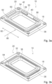
- the cutting device 20 preferably has at least the cutting element 30 and at least the counter-cutting element 32, wherein the cutting element 30 is fixed to the hold-down element 16 and extends at least largely around a through-opening 34 of the hold-down element 16 (cf. Figures 3a and 4 ).
- the counter-cutting element 32 is preferably fixed to the further hold-down element 18 and extends at least largely around a through-opening 36 of the further hold-down element 18 (cf. Figure 3b ).
- the cutting element 30 can be fixed to the hold-down element 16 by means of a material, force-locking and/or form-fitting connection, such as by means of a screw connection, a clamp connection, a rivet connection, a welded connection or the like.
- the cutting element 30, in particular in an alternative embodiment of the hold-down device 10, is fixed to the hold-down element 16 in an exchangeable manner, in particular in a non-destructively separable manner.
- the cutting element 30 can be exchangeable as a whole from the hold-down element 16, or the cutting element 30 can have individually detachable cutting segments 56, 58, 60 (in Figures 3a and 4 (indicated by dashed lines, for example, by the subdivision of the cutting element 30), which together form the cutting element 30 and are individually, in particular individually, separable from the hold-down element 16, in particular are individually fixed to the hold-down element 16.
- a single one of the cutting segments 56, 58, 60 or a plurality of cutting segments 56, 58, 60 can be individually, in particular individually, detached from the hold-down element 16 and removed therefrom depending on a requirement for a cut or incision 76, 78 to be made. It is advantageously possible to constructively easily adapt the cutting, embossing, or severing cut path on the packaging material 14.
- the cutting element 30 is permanently fixed to the hold-down element 16, for example by a welded connection or by a combination of a welded connection and a form-fitting and/or material-fitting connection, such as for example, by a welded screw connection, by a welded rivet connection, or the like.
- the cutting element 30 may be formed from individual cutting segments 56, 58, 60, wherein at least one or more of the cutting segments 56, 58, 60 is or are arranged on the hold-down element 16 and one or more of the cutting segments 56, 58, 60 is or are arranged on the further hold-down element 18.
- Other arrangements of the cutting segments 56, 58, 60 or configurations of the cutting element 30 that appear appropriate to a person skilled in the art are also conceivable.
- the counter-cutting element 32 can be fixed to the further hold-down element 18 by means of a material, force-locking and/or form-fitting connection, such as by means of a screw connection, a clamp connection, a rivet connection, a welded connection or the like.
- the counter-cutting element 32 is permanently fixed to the further hold-down element 18, such as by a welded connection or by a combination of a welded connection and a form-locking and/or material-locking connection, such as by a welded screw connection, a welded rivet connection or the like.
- the counter-cutting element 32 may be formed from individual counter-cutting segments, wherein at least one or more of the counter-cutting segments is or are arranged on the further hold-down element 18 and one or more of the counter-cutting segments is or are arranged on the hold-down element 16, in particular depending on an arrangement of individual cutting segments 56, 58, 60 of the cutting element 30 on the hold-down element 16 and/or on the further hold-down element 18.
- the cutting element 30 is formed in one piece with the hold-down element 16 and the counter-cutting element 32 is formed in one piece with the further hold-down element 18.
- the Figures 3a and 4 The hold-down elements 16 shown differ fundamentally only in the arrangement and/or design of the cutting element 30 on the respective hold-down element 16.
- the description of the hold-down elements 16 given here therefore relates to both exemplary embodiments, with a specific reference to the corresponding figure being given with regard to the cutting elements 30.
- the cutting element 30 preferably extends over a hold-down surface 62 of the hold-down element 16.
- the cutting element 30 preferably extends along an at least substantially vertical direction over the hold-down surface 62, in particular in the manner of a cutting extension.
- the counter-cutting element 32 is preferably designed as a groove, the boundary edge of which cooperates with the cutting element 30 to sever or cut into the packaging material 14 in a manner already known to a person skilled in the art.
- the cutting element 30 extends into the counter-cutting element 32.
- the packaging material 14 is cut or severed, in particular sheared, at least in places in a manner already known to a person skilled in the art by means of a cooperation of the cutting edge 42 and the boundary edge.
- Figure 2 For example, this interaction can be seen.
- the cutting element 30, particularly in an alternative embodiment of the hold-down device 10 comprises at least one cutting segment 56, 58 and at least one further cutting segment 60, wherein the cutting segment 56, 58 has a maximum height that is different from a maximum height of the further cutting segment 60.
- the maximum height of the cutting segment 56, 58 and/or the maximum height of the further cutting segment 60 extends along a direction extending at least substantially perpendicular to the hold-down surface 62 of the hold-down element 16.
- the maximum height of the cutting segment 56, 58 and/or the maximum height of the further cutting segment 60 extends along a direction extending at least substantially parallel to a direction of movement of the hold-down element 16 relative to the further hold-down element 18.
- the maximum height of the cutting segment 56, 58 is greater than the maximum height of the further cutting segment 60. However, it is also conceivable that the maximum height of the cutting segment 56, 58 is less than the maximum height of the further cutting segment 60. Preferably, the maximum height of the further cutting segment 60 corresponds to more than 25%, preferably more than 50% and most preferably less than 90% of the maximum height of the cutting segment 56, 58.
- the cutting element 30 is provided in a configuration with cutting segments 56, 58, 60 of different heights for cutting into the packaging material 14, in particular for not completely severing the packaging material 14 (cf.
- FIG. 6c and 6d in which incisions 76, 78 with different maximum cutting depths are shown in the packaging material 14 by means of the cutting segments 56, 58, 60).
- the maximum height of the cutting segment 56, 58 and/or the maximum height of the further cutting segment 60 correspond in particular to less than 95%, preferably less than 90% and particularly preferably less than 80% of a maximum material thickness of the packaging material 14 (cf. for example Figures 6c and 6d , in which a dashed center line schematically indicates a 50% mark of a maximum material thickness of the packaging material 14).
- the hold-down device 10 can have at least one surface structure unit 38 (indicated by dashed lines in Figures 3a and 3b), in particular comprising a plurality of grooves and/or webs, which is arranged at least between the through-opening 34 of the hold-down element 16 and the cutting element 30 of the cutting device 20 arranged on the hold-down element 16 and/or between the through-opening 36 of the further hold-down element 18 and the counter-cutting element 32 of the cutting device 20 arranged on the further hold-down element 18.
- the surface structure unit 38 is arranged at least partially on the hold-down surface 62 of the hold-down element 16 and/or at least partially on the hold-down surface 64 of the further hold-down element 18, in particular formed by them.
- the surface structure unit 38 can be designed as a ribbing, a grid, or any other surface structure that appears appropriate to a person skilled in the art and that controls or influences the formation of wrinkles. It is also conceivable that the hold-down device 10 is designed independently of the surface structure unit 38, in particular is designed without a surface structure unit 38.
- Figure 4 shows an embodiment of the hold-down element 16, in which the cutting device 20 is designed such that the packaging material 14 is severed at least in places and/or cut at least in places such that a blank 22 that can be produced from the packaging material 14 and from which a three-dimensional shaped body, in particular a food receptacle, can be produced by means of the forming device 12, is connected to the packaging material 14 via at least, in particular more than, two connecting sections 24, 26, 28, in particular connecting webs.
- the cutting device 20 has at least the cutting element 30, which is arranged at least largely around the through-opening 34, and a plurality of cutting-free regions 40, wherein the cutting-free regions 40 are arranged irregularly distributed on the cutting element 30, in particular to subdivide the cutting edge 42 of the cutting element 30.
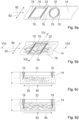
- Figures 5a to 5d show possible weakenings of the packaging material 14 with the hold-down device 10, whereby, depending on the application, the cutting device 20 is designed according to the weakenings to be introduced.
- Figure 5a For example, embossings or cuts 76, 78 extending completely around the blank 22 or the blanks 22, which do not completely pass through the material thickness of the packaging material 14, are shown.
- Figure 5b For example, weakenings in the form of separating cuts that do not extend completely around the blank 22 or the blanks 22 are shown, so that the blank 22 or the blanks 22 is or are still connected to the packaging material 14 via at least one connecting section 24. This is for example by means of a cutting element 30, as shown in Figure 3a shown, is feasible.
- weakenings are shown in the form of grid-shaped or transverse separating cuts, wherein the blank 22 or the blanks 22 are still connected to the packaging material 14 via at least two connecting sections 24, 26.
- weakenings are shown in the form of separating cuts that do not completely extend around the blank 22 or the blanks 22, so that the blank 22 or the blanks 22 are still connected to the packaging material 14 via at least three connecting sections 24, 26, 28. This is, in particular, up to a precise arrangement of the cut-free areas 40 and a geometric shape, for example by means of a cutting element 30, as shown in Figure 4 shown, which has several cutting-free areas 40, but otherwise extends largely around the through-opening 34 of the hold-down element 16.
- Figures 6a to 6d show possible weakenings of the packaging material 14 with the hold-down device 10, whereby, depending on the application, the cutting device 20 is designed according to the weakenings to be introduced.
- the weakenings are shown in the Figures 6a to 6d preferably formed by incisions 76, 78 which do not completely extend through the maximum material thickness of the packaging material 14 and which can be introduced into the packaging material 14 with different maximum heights, in particular by the cutting segments 56, 58, 60.
- Figure 6a partial section of a packaging material web of the packaging material 14 is shown schematically with, for example, incisions 76, 78 made therein for forming blanks 22.
- Incisions 76 which extend largely along a fiber direction of the packaging material 14 and/or along the conveying direction 80 of the production machine 44, are shown in the Figures 6a and 6b shown with thin lines. Further cuts 78, which extend mostly along a transverse direction 82 running transversely, in particular at least substantially perpendicularly, to the fiber direction and/or the conveying direction 80, are shown in the Figures 6a and 6b shown with thick lines.
- the incisions 76 can preferably be made in the packaging material 14 by means of the further cutting segments 60 of the cutting element 30, whose cutting edges 42 extend for the most part at least substantially parallel to the conveying direction 80.
- the further incisions 78 can preferably be made in the packaging material 14 by means of the cutting segments 56, 58 of the cutting element 30, whose cutting edges 42 extend for the most part at least substantially perpendicular to the conveying direction 80.
- Figures 6b to 6d Fibers of the packaging material 14 are shown schematically, in particular to allow an illustration of an alignment of the fiber direction.
- Figure 6c is a sectional view along the line VIc - VIc Figure 6b shown, wherein a cutting plane preferably runs at least substantially perpendicular to the fiber direction and/or the conveying direction 80.
- Figure 6d is a sectional view along the line VId - Vld from Figure 6b shown, wherein a cutting plane preferably runs at least substantially parallel to the fiber direction and/or the conveying direction 80, in particular contains the fiber direction and/or the conveying direction 80.
- the packaging material 14 comprises, for example, two layers, in particular a paper layer (thick layer) and a polymer layer (thin layer). However, it is also conceivable for the packaging material 14 to comprise only a single layer, in particular a paper layer or the like, wherein the incision 76 and the further incision 78 can be made in a similar manner.
- the incision 76 is also conceivable for the incision 76 to be made in the packaging material 14 on a side of the packaging material 14 facing away from the further incision 78, in particular depending on an arrangement of the cutting segments 56, 58, 60 on the hold-down element 16 and/or on the further hold-down element 18.
- Figure 7 shows a schematic process sequence of a process 52 for forming the packaging material 14 by means of the forming device 12, on which the hold-down device 10 is arranged.
- the packaging material 14 is fed to the forming device 12.
- the hold-down device 10 is closed.
- at least the hold-down element 16 and the cutting element 30 of the cutting device 20 are moved at least substantially synchronously, in particular before the packaging material 14 is formed by the forming device 12.
- the packaging material 14 is severed and/or cut at least in places by closing the hold-down device 10, in particular before the packaging material 14 is formed by the forming device 12.
- the cutting device 20 severes and/or cuts the packaging material 14 in places such that the blank(s) 22 produced from the packaging material 14, from which a three-dimensional shaped body, in particular a food receptacle, is produced by means of the forming device 12, has at least in particular more than two connecting sections 24, 26, 28, in particular connecting webs, is/are connected to the packaging material 14.
- the forming device 12 is closed in order to produce one or more shaped bodies from the blank(s) 22 during one stroke of the punch 46.
- the produced shaped body can be further processed.
- the shaped body can be filled with food
- method step 74 the shaped body filled with food can be closed.
- the packaging material 14, in particular for producing the blank 22 from which a three-dimensional shaped body, in particular a food receptacle, can be produced by means of the forming device 12, is cut at least in places, in particular not completely severed, wherein a maximum cutting depth of at least one of the cuts 76, 78 depends on the fiber direction of the packaging material 14 and/or on the conveying direction 80.
- the cut 76 made in the packaging material 14 by means of the cutting element 30, which extends largely along the fiber direction and/or along the conveying direction 80, has a maximum cutting depth which, in particular with respect to a numerical value, is smaller, in particular smaller, than a maximum cutting depth of the further cut 78 made in the packaging material 14 by means of the cutting element 30, which extends largely along a direction transverse, in particular at least substantially perpendicular, to the fiber direction and/or to the Conveying direction 80 extending transverse direction 82 (cf. Figures 6c and 6d ).
- the method 52 may also include further or alternative method steps of the method 52, which appear to be useful to a person skilled in the art. With regard to further features of the method 52, reference is generally made to the description of Figures 1 to 5d which are to be read analogously to Procedure 52.
Landscapes
- Engineering & Computer Science (AREA)
- Mechanical Engineering (AREA)
- Life Sciences & Earth Sciences (AREA)
- Forests & Forestry (AREA)
- Auxiliary Devices For And Details Of Packaging Control (AREA)
Claims (14)
- Dispositif de serre-flanc pour un dispositif de formage (12), qui est prévu pour une fabrication de corps moulés tridimensionnels à partir de matériau d'emballage (14), comportant au moins un élément de serre-flanc (16) et comportant au moins un autre élément de serre-flanc (18), qui sont montés mobiles l'un par rapport à l'autre et sont prévus pour un maintien du matériau d'emballage (14) pendant une opération de formage, ainsi que comportant au moins un dispositif de coupe (20) qui, en particulier avant un formage du matériau d'emballage (14), est prévu pour couper au moins par endroits le matériau d'emballage (14) et/ou pour l'entailler au moins par endroits, dans lequel le dispositif de coupe (20) est disposé de telle sorte sur l'élément de serre-flanc (16) et/ou sur l'autre élément de serre-flanc (18), que le dispositif de coupe (20) peut être déplacé, en particulier est déplacé, au moins sensiblement de manière synchrone par rapport à un mouvement relatif de l'élément de serre-flanc (16) et de l'autre élément de serre-flanc (18), caractérisé en ce que le dispositif de coupe (20) comprend au moins un élément de coupe (30), en particulier disposé au moins en grande partie autour d'une ouverture de passage (34), lequel élément de coupe comprend au moins un segment de coupe (56, 58) et au moins un autre segment de coupe (60), dans lequel le segment de coupe (56, 58) présente une hauteur maximale qui est différente d'une hauteur maximale de l'autre segment de coupe (60), pour pratiquer une entaille (76) dans le matériau d'emballage (14) et une autre entaille (78) dans le matériau d'emballage (14), dans lequel une profondeur de coupe maximale de l'entaille (76) est différente d'une profondeur de coupe maximale de l'autre entaille (78).
- Dispositif de serre-flanc selon la revendication 1, caractérisé en ce que le dispositif de coupe (20) est réalisé de telle sorte que le matériau d'emballage (14) est coupé au moins par endroits et/ou est entaillé au moins par endroits de telle sorte qu'une découpe (22) pouvant être produite à partir du matériau d'emballage (14), à partir de laquelle un corps moulé tridimensionnel, en particulier un récipient de réception de denrées alimentaires, peut être fabriqué à l'aide du dispositif de formage (12), est reliée au matériau d'emballage (14) par au moins, en particulier plus de, deux sections de liaison (24, 26, 28), en particulier des barrettes de liaison.
- Dispositif de serre-flanc selon la revendication 1 ou 2, caractérisé en ce que le dispositif de coupe (20) présente au moins l'élément de coupe (30) et au moins un contre-élément de coupe (32), dans lequel l'élément de coupe (30) est fixé à l'élément de serre-flanc (16) et le contre-élément de coupe (32) est fixé à l'autre élément de serre-flanc (18).
- Dispositif de serre-flanc selon l'une des revendications précédentes, caractérisé en ce que le dispositif de coupe (20) présente au moins l'élément de coupe (30) et au moins un contre-élément de coupe (32), dans lequel l'élément de coupe (30) est réalisé d'une seule pièce avec l'élément de serre-flanc (16) et le contre-élément de coupe (32) est réalisé d'une seule pièce avec l'autre élément de serre-flanc (18).
- Dispositif de serre-flanc selon l'une des revendications précédentes, caractérisé en ce que le dispositif de coupe (20) présente au moins l'élément de coupe (30) et au moins un contre-élément de coupe (32), dans lequel l'élément de coupe (30) est fixé à l'élément de serre-flanc (16) et s'étend au moins en grande partie autour d'une ouverture de passage (34) de l'élément de serre-flanc (16), et dans lequel le contre-élément de coupe (32) est fixé à l'autre élément de serre-flanc (18) et s'étend au moins en grande partie autour d'une ouverture de passage (36) de l'autre élément de serre-flanc (18).
- Dispositif de serre-flanc selon l'une des revendications précédentes, caractérisé par au moins une unité de structure de surface (38), comprenant en particulier une pluralité de rainures et/ou de nervures, qui est disposée au moins entre une ouverture de passage (34) de l'élément de serre-flanc (16) et l'élément de coupe (30) du dispositif de coupe (20) disposé sur l'élément de serre-flanc (16) et/ou entre une ouverture de passage (36) de l'autre élément de serre-flanc (18) et un contre-élément de coupe (32) du dispositif de coupe (20) disposé sur l'autre élément de serre-flanc (18).
- Dispositif de serre-flanc selon l'une des revendications précédentes, caractérisé en ce que le dispositif de coupe (20) présente au moins l'élément de coupe (30), disposé en particulier au moins en grande partie autour d'une ouverture de passage (34), et une pluralité de zones sans coupe (40), dans lequel les zones sans coupe (40) sont disposées réparties de manière irrégulière sur l'élément de coupe (30), en particulier pour une subdivision d'une arête de coupe (42) de l'élément de coupe (30).
- Machine de production pour un traitement de matériau d'emballage (14), en particulier de matériau d'emballage (14) comprenant un matériau fibreux, comportant au moins un dispositif de formage (12) présentant en particulier au moins un poinçon (46) et une matrice (48), et comportant au moins un dispositif de serre-flanc selon l'une des revendications précédentes disposé sur le dispositif de formage (12).
- Machine de production selon la revendication 8, caractérisée par au moins une unité de commande ou de régulation (50) qui est conçue pour commander ou réguler un mouvement au moins sensiblement synchrone de l'élément de serre-flanc (16) et de l'élément de coupe (30) du dispositif de coupe (20) et/ou un mouvement au moins sensiblement synchrone de l'autre élément de serre-flanc (18) et d'un contre-élément de coupe (32) du dispositif de coupe (20).
- Procédé pour un formage de matériau d'emballage (14), en particulier de matériau d'emballage (14) comprenant un matériau fibreux, à l'aide d'un dispositif de formage (12) sur lequel est disposé un dispositif de serre-flanc selon l'une des revendications 1 à 7, dans lequel au moins l'élément de serre-flanc (16) et l'élément de coupe (30) du dispositif de coupe (20) sont déplacés au moins sensiblement de manière synchrone, en particulier avant qu'un formage du matériau d'emballage (14) ne soit effectué avec le dispositif de formage (12), caractérisé en ce qu'une entaille (76) est pratiquée dans le matériau d'emballage (14) à l'aide de l'au moins un segment de coupe (56, 58) et une autre entaille (78) est pratiquée dans le matériau d'emballage (14) à l'aide de l'au moins un autre segment de coupe (60), dans lequel une profondeur de coupe maximale de l'entaille (76) est différente d'une profondeur de coupe maximale de l'autre entaille (78).
- Procédé selon la revendication 10, dans lequel le matériau d'emballage (14) est coupé et/ou entaillé au moins par endroits par une fermeture du dispositif de serre-flanc, en particulier avant qu'un formage du matériau d'emballage (14) ne soit effectué avec le dispositif de formage (12).
- Procédé selon la revendication 10 ou 11, dans lequel le dispositif de coupe (20) coupe le matériau d'emballage (14) par endroits et/ou l'entaille au moins par endroits de telle sorte qu'une découpe (22) produite à partir du matériau d'emballage (14), à partir de laquelle un corps moulé tridimensionnel, en particulier un récipient de réception de denrées alimentaires, est fabriqué à l'aide du dispositif de formage (12), est reliée au matériau d'emballage (14) par au moins, en particulier plus de, deux sections de liaison (24, 26, 28), en particulier des barrettes de liaison.
- Procédé selon l'une des revendications 10 à 12, dans lequel le matériau d'emballage (14) est entaillé au moins par endroits et une profondeur de coupe maximale d'au moins une entaille (76, 78) dépend d'une direction de fibres du matériau d'emballage (14) et/ou d'une direction de transport (80) d'une machine de production comprenant le dispositif de serre-flanc, en particulier d'une orientation par rapport à cette direction.
- Procédé selon l'une des revendications 10 à 13, dans lequel le matériau d'emballage (14) est entaillé au moins par endroits, dans lequel au moins l'entaille (76) s'étendant en grande partie le long d'une direction de fibres du matériau d'emballage (14) et/ou le long d'une direction de transport (80) d'une machine de production comprenant le dispositif de serre-flanc et au moins l'autre entaille (78) s'étendant en grande partie le long d'une direction transversale (82) s'étendant transversalement, en particulier au moins sensiblement perpendiculairement, à la direction de fibres et/ou à la direction de transport (80) sont pratiquées dans le matériau d'emballage (14).
Applications Claiming Priority (1)
| Application Number | Priority Date | Filing Date | Title |
|---|---|---|---|
| DE102022104583.8A DE102022104583A1 (de) | 2022-02-25 | 2022-02-25 | Niederhaltervorrichtung für eine Umformvorrichtung, Verfahren zu einer Umformung von Verpackungsmaterial mittels der Umformvorrichtung sowie Produktionsmaschine mit einer derartigen Umformvorrichtung |
Publications (3)
| Publication Number | Publication Date |
|---|---|
| EP4234189A2 EP4234189A2 (fr) | 2023-08-30 |
| EP4234189A3 EP4234189A3 (fr) | 2023-10-11 |
| EP4234189B1 true EP4234189B1 (fr) | 2025-07-09 |
Family
ID=85382643
Family Applications (1)
| Application Number | Title | Priority Date | Filing Date |
|---|---|---|---|
| EP23158585.2A Active EP4234189B1 (fr) | 2022-02-25 | 2023-02-24 | Dispositif de maintien pour un dispositif de formage, procédé de formage d'un matériau d'emballage au moyen du dispositif de formage ainsi que machine de production dotée d'un tel dispositif de formage |
Country Status (2)
| Country | Link |
|---|---|
| EP (1) | EP4234189B1 (fr) |
| DE (1) | DE102022104583A1 (fr) |
Families Citing this family (1)
| Publication number | Priority date | Publication date | Assignee | Title |
|---|---|---|---|---|
| WO2025257804A1 (fr) * | 2024-06-13 | 2025-12-18 | Tecnoform S.R.L. | Système et procédé de production de corps façonnés |
Family Cites Families (9)
| Publication number | Priority date | Publication date | Assignee | Title |
|---|---|---|---|---|
| US4104349A (en) * | 1976-02-04 | 1978-08-01 | Hillgenberg David E | Method of making a perforated, molded container |
| DE3037050A1 (de) * | 1980-10-01 | 1982-05-27 | Basf Ag, 6700 Ludwigshafen | Verfahren und vorrichtung zum herstellen eines flaechigen profilierten verbundkoerpers |
| JPS58217318A (ja) * | 1982-06-11 | 1983-12-17 | Matsushita Refrig Co | 合成樹脂品の裁断面バリ処理方法 |
| DE4304951C2 (de) * | 1993-02-18 | 1997-09-11 | Wachsmuth & Co Werkzeugbau | Werkzeug zum Stanzen von Einfach- und Mehrfachbehältern aus Kunststoffolie |
| DE20116769U1 (de) | 2001-10-12 | 2001-12-20 | Marbach Werkzeugbau GmbH, 74080 Heilbronn | Niederhalter für ein Thermoformwerkzeug |
| DE102007050637B4 (de) | 2007-10-23 | 2013-10-10 | Rpc Bebo-Plastik Gmbh | Verfahren zur Herstellung thermogeformter Artikel sowie Werkzeug zu deren Herstellung |
| JP6101000B2 (ja) | 2012-01-30 | 2017-03-22 | 東洋製罐株式会社 | 紙成形体を製造する方法及びその装置 |
| DE102014106427A1 (de) | 2014-05-08 | 2015-11-12 | Technische Universität Dresden | Verfahren und Vorrichtung zur Herstellung von Formteilen aus einer Faserwerkstoffbahn |
| DE102018113512A1 (de) | 2018-06-06 | 2019-12-12 | Progress Packaging Gmbh | Vorrichtung und Verfahren zum Herstellen von Füllmaterial mit Presseinrichtung |
-
2022
- 2022-02-25 DE DE102022104583.8A patent/DE102022104583A1/de active Pending
-
2023
- 2023-02-24 EP EP23158585.2A patent/EP4234189B1/fr active Active
Also Published As
| Publication number | Publication date |
|---|---|
| EP4234189A3 (fr) | 2023-10-11 |
| DE102022104583A1 (de) | 2023-08-31 |
| EP4234189A2 (fr) | 2023-08-30 |
Similar Documents
| Publication | Publication Date | Title |
|---|---|---|
| EP3140200B1 (fr) | Procédé et dispositif de fabrication de pièces moulées à partir d'une bande de matière fibreuse | |
| EP2125542B1 (fr) | Dispositif de fermeture en plastique pourvu d'un tube coupant | |
| DE102007014314A1 (de) | Bogenstanz- und -prägemaschine mit hydraulischem Antrieb | |
| DE19543860A1 (de) | Verfahren und Vorrichtung zum Formen geschlitzter und gefalzter Kartonformteile | |
| DE102007050637B4 (de) | Verfahren zur Herstellung thermogeformter Artikel sowie Werkzeug zu deren Herstellung | |
| EP2858798B1 (fr) | Dispositif et procédé de décorticage et de séparation de découpes | |
| EP0100016B1 (fr) | Dispositif d'ouverture pour un récipient parallèlépipédique contenant un fluide | |
| EP0813954B1 (fr) | Procédé et dispositif pour la fabrication de matériaux de rembourrage et matériaux de rembourrage ainsi fabriqués | |
| EP1103369B1 (fr) | Procédé et dispositif pour la fabrication de collerettes pour des boítes avec un couvercle à charnière | |
| EP2844572B1 (fr) | Emballage pour cigarettes | |
| EP4234189A2 (fr) | Dispositif de maintien pour un dispositif de formage, procédé de formage d'un matériau d'emballage au moyen du dispositif de formage ainsi que machine de production dotée d'un tel dispositif de formage | |
| DE102022117737A1 (de) | Verfahren zur Herstellung mindestens eines Verpackungselements | |
| DE102008011051A1 (de) | Bogenstanz- und -prägemaschine | |
| EP2522472B1 (fr) | Unité de perforation d'une machine d'emballage | |
| DE102015011399B4 (de) | Vorrichtung und Verfahren zum Rillen, Perforieren, Schneiden und Ritzen von flächigen Elementen | |
| EP3403782B1 (fr) | Outil et procédé de fabrication d'un objet utile en feuille de carton | |
| EP2289660B1 (fr) | Dispositif et procédé de découpe pour des matériels TDS ou ODF avec deux paires de rouleaux d'entraînement | |
| EP0698454A1 (fr) | Procédé et dispositif ainsi que poinçon de découpe pour la réalisation de perforations de déchirement sur des produits en carton ondulé | |
| EP3919215B1 (fr) | Dispositif de soudage, ainsi que procédé de soudage d'un élément de sortie sur une matière d'emballage | |
| EP4368382A1 (fr) | Dispositif et procédé de formage d'un élément d'emballage | |
| DE102008034764A1 (de) | Werkzeug für eine Bogenstanzmaschine | |
| EP3915772B1 (fr) | Dispositif et procédé de liaison détachable des couches chevauchées de carton ou de stratifié en matière plastique | |
| EP3330070A2 (fr) | Dispositif et procédé destiné à rainurer du carton ondulé ou du carton homogène | |
| DE102004001758B4 (de) | Vorrichtung zum Schneiden von bahnartigem Material sowie Verfahren zur Erzeugung von Querschnitten in einem bahnartigen Material | |
| EP1882565A2 (fr) | Procédé de döcoupe et presse de découpage et de rainurage |
Legal Events
| Date | Code | Title | Description |
|---|---|---|---|
| PUAI | Public reference made under article 153(3) epc to a published international application that has entered the european phase |
Free format text: ORIGINAL CODE: 0009012 |
|
| STAA | Information on the status of an ep patent application or granted ep patent |
Free format text: STATUS: THE APPLICATION HAS BEEN PUBLISHED |
|
| AK | Designated contracting states |
Kind code of ref document: A2 Designated state(s): AL AT BE BG CH CY CZ DE DK EE ES FI FR GB GR HR HU IE IS IT LI LT LU LV MC ME MK MT NL NO PL PT RO RS SE SI SK SM TR |
|
| PUAL | Search report despatched |
Free format text: ORIGINAL CODE: 0009013 |
|
| AK | Designated contracting states |
Kind code of ref document: A3 Designated state(s): AL AT BE BG CH CY CZ DE DK EE ES FI FR GB GR HR HU IE IS IT LI LT LU LV MC ME MK MT NL NO PL PT RO RS SE SI SK SM TR |
|
| RIC1 | Information provided on ipc code assigned before grant |
Ipc: B29C 51/32 20060101ALI20230905BHEP Ipc: B29C 51/26 20060101ALI20230905BHEP Ipc: B26F 1/44 20060101AFI20230905BHEP |
|
| STAA | Information on the status of an ep patent application or granted ep patent |
Free format text: STATUS: REQUEST FOR EXAMINATION WAS MADE |
|
| 17P | Request for examination filed |
Effective date: 20240410 |
|
| RBV | Designated contracting states (corrected) |
Designated state(s): AL AT BE BG CH CY CZ DE DK EE ES FI FR GB GR HR HU IE IS IT LI LT LU LV MC ME MK MT NL NO PL PT RO RS SE SI SK SM TR |
|
| GRAP | Despatch of communication of intention to grant a patent |
Free format text: ORIGINAL CODE: EPIDOSNIGR1 |
|
| STAA | Information on the status of an ep patent application or granted ep patent |
Free format text: STATUS: GRANT OF PATENT IS INTENDED |
|
| INTG | Intention to grant announced |
Effective date: 20250410 |
|
| GRAS | Grant fee paid |
Free format text: ORIGINAL CODE: EPIDOSNIGR3 |
|
| GRAA | (expected) grant |
Free format text: ORIGINAL CODE: 0009210 |
|
| STAA | Information on the status of an ep patent application or granted ep patent |
Free format text: STATUS: THE PATENT HAS BEEN GRANTED |
|
| AK | Designated contracting states |
Kind code of ref document: B1 Designated state(s): AL AT BE BG CH CY CZ DE DK EE ES FI FR GB GR HR HU IE IS IT LI LT LU LV MC ME MK MT NL NO PL PT RO RS SE SI SK SM TR |
|
| REG | Reference to a national code |
Ref country code: GB Ref legal event code: FG4D Free format text: NOT ENGLISH |
|
| REG | Reference to a national code |
Ref country code: CH Ref legal event code: EP |
|
| REG | Reference to a national code |
Ref country code: IE Ref legal event code: FG4D Free format text: LANGUAGE OF EP DOCUMENT: GERMAN |
|
| REG | Reference to a national code |
Ref country code: DE Ref legal event code: R096 Ref document number: 502023001292 Country of ref document: DE |
|
| REG | Reference to a national code |
Ref country code: DE Ref legal event code: R081 Ref document number: 502023001292 Country of ref document: DE Owner name: SYNTEGON TECHNOLOGY GMBH, DE Free format text: FORMER OWNER: SYNTEGON TECHNOLOGY GMBH, 71332 WAIBLINGEN, DE Ref country code: DE Ref legal event code: R081 Ref document number: 502023001292 Country of ref document: DE Owner name: HESSER PACKAGING GMBH, DE Free format text: FORMER OWNER: SYNTEGON TECHNOLOGY GMBH, 71332 WAIBLINGEN, DE |
|
| REG | Reference to a national code |
Ref country code: CH Ref legal event code: W10 Free format text: ST27 STATUS EVENT CODE: U-0-0-W10-W00 (AS PROVIDED BY THE NATIONAL OFFICE) Effective date: 20251006 |
|
| RAP4 | Party data changed (patent owner data changed or rights of a patent transferred) |
Owner name: SYNTEGON TECHNOLOGY GMBH |
|
| REG | Reference to a national code |
Ref country code: NL Ref legal event code: MP Effective date: 20250709 |
|
| PG25 | Lapsed in a contracting state [announced via postgrant information from national office to epo] |
Ref country code: PT Free format text: LAPSE BECAUSE OF FAILURE TO SUBMIT A TRANSLATION OF THE DESCRIPTION OR TO PAY THE FEE WITHIN THE PRESCRIBED TIME-LIMIT Effective date: 20251110 |
|
| PG25 | Lapsed in a contracting state [announced via postgrant information from national office to epo] |
Ref country code: NL Free format text: LAPSE BECAUSE OF FAILURE TO SUBMIT A TRANSLATION OF THE DESCRIPTION OR TO PAY THE FEE WITHIN THE PRESCRIBED TIME-LIMIT Effective date: 20250709 |
|
| PG25 | Lapsed in a contracting state [announced via postgrant information from national office to epo] |
Ref country code: IS Free format text: LAPSE BECAUSE OF FAILURE TO SUBMIT A TRANSLATION OF THE DESCRIPTION OR TO PAY THE FEE WITHIN THE PRESCRIBED TIME-LIMIT Effective date: 20251109 |
|
| PG25 | Lapsed in a contracting state [announced via postgrant information from national office to epo] |
Ref country code: NO Free format text: LAPSE BECAUSE OF FAILURE TO SUBMIT A TRANSLATION OF THE DESCRIPTION OR TO PAY THE FEE WITHIN THE PRESCRIBED TIME-LIMIT Effective date: 20251009 |
|
| REG | Reference to a national code |
Ref country code: LT Ref legal event code: MG9D |
|
| PG25 | Lapsed in a contracting state [announced via postgrant information from national office to epo] |
Ref country code: FI Free format text: LAPSE BECAUSE OF FAILURE TO SUBMIT A TRANSLATION OF THE DESCRIPTION OR TO PAY THE FEE WITHIN THE PRESCRIBED TIME-LIMIT Effective date: 20250709 |
|
| PG25 | Lapsed in a contracting state [announced via postgrant information from national office to epo] |
Ref country code: HR Free format text: LAPSE BECAUSE OF FAILURE TO SUBMIT A TRANSLATION OF THE DESCRIPTION OR TO PAY THE FEE WITHIN THE PRESCRIBED TIME-LIMIT Effective date: 20250709 |
|
| PG25 | Lapsed in a contracting state [announced via postgrant information from national office to epo] |
Ref country code: GR Free format text: LAPSE BECAUSE OF FAILURE TO SUBMIT A TRANSLATION OF THE DESCRIPTION OR TO PAY THE FEE WITHIN THE PRESCRIBED TIME-LIMIT Effective date: 20251010 |
|
| PG25 | Lapsed in a contracting state [announced via postgrant information from national office to epo] |
Ref country code: SE Free format text: LAPSE BECAUSE OF FAILURE TO SUBMIT A TRANSLATION OF THE DESCRIPTION OR TO PAY THE FEE WITHIN THE PRESCRIBED TIME-LIMIT Effective date: 20250709 |
|
| PG25 | Lapsed in a contracting state [announced via postgrant information from national office to epo] |
Ref country code: LV Free format text: LAPSE BECAUSE OF FAILURE TO SUBMIT A TRANSLATION OF THE DESCRIPTION OR TO PAY THE FEE WITHIN THE PRESCRIBED TIME-LIMIT Effective date: 20250709 |
|
| PG25 | Lapsed in a contracting state [announced via postgrant information from national office to epo] |
Ref country code: BG Free format text: LAPSE BECAUSE OF FAILURE TO SUBMIT A TRANSLATION OF THE DESCRIPTION OR TO PAY THE FEE WITHIN THE PRESCRIBED TIME-LIMIT Effective date: 20250709 Ref country code: PL Free format text: LAPSE BECAUSE OF FAILURE TO SUBMIT A TRANSLATION OF THE DESCRIPTION OR TO PAY THE FEE WITHIN THE PRESCRIBED TIME-LIMIT Effective date: 20250709 |
|
| PG25 | Lapsed in a contracting state [announced via postgrant information from national office to epo] |
Ref country code: RS Free format text: LAPSE BECAUSE OF FAILURE TO SUBMIT A TRANSLATION OF THE DESCRIPTION OR TO PAY THE FEE WITHIN THE PRESCRIBED TIME-LIMIT Effective date: 20251009 |
|
| PG25 | Lapsed in a contracting state [announced via postgrant information from national office to epo] |
Ref country code: ES Free format text: LAPSE BECAUSE OF FAILURE TO SUBMIT A TRANSLATION OF THE DESCRIPTION OR TO PAY THE FEE WITHIN THE PRESCRIBED TIME-LIMIT Effective date: 20250709 |
|
| PG25 | Lapsed in a contracting state [announced via postgrant information from national office to epo] |
Ref country code: SM Free format text: LAPSE BECAUSE OF FAILURE TO SUBMIT A TRANSLATION OF THE DESCRIPTION OR TO PAY THE FEE WITHIN THE PRESCRIBED TIME-LIMIT Effective date: 20250709 |
|
| PG25 | Lapsed in a contracting state [announced via postgrant information from national office to epo] |
Ref country code: DK Free format text: LAPSE BECAUSE OF FAILURE TO SUBMIT A TRANSLATION OF THE DESCRIPTION OR TO PAY THE FEE WITHIN THE PRESCRIBED TIME-LIMIT Effective date: 20250709 |
|
| PGFP | Annual fee paid to national office [announced via postgrant information from national office to epo] |
Ref country code: DE Payment date: 20260217 Year of fee payment: 4 |
|
| PGFP | Annual fee paid to national office [announced via postgrant information from national office to epo] |
Ref country code: AT Payment date: 20260301 Year of fee payment: 4 |
|
| PGFP | Annual fee paid to national office [announced via postgrant information from national office to epo] |
Ref country code: IT Payment date: 20260228 Year of fee payment: 4 |
|
| REG | Reference to a national code |
Ref country code: DE Ref legal event code: R081 Ref document number: 502023001292 Country of ref document: DE Owner name: HESSER PACKAGING GMBH, DE Free format text: FORMER OWNER: SYNTEGON TECHNOLOGY GMBH, 70372 STUTTGART, DE |
|
| PG25 | Lapsed in a contracting state [announced via postgrant information from national office to epo] |
Ref country code: CZ Free format text: LAPSE BECAUSE OF FAILURE TO SUBMIT A TRANSLATION OF THE DESCRIPTION OR TO PAY THE FEE WITHIN THE PRESCRIBED TIME-LIMIT Effective date: 20250709 |
|
| PG25 | Lapsed in a contracting state [announced via postgrant information from national office to epo] |
Ref country code: SK Free format text: LAPSE BECAUSE OF FAILURE TO SUBMIT A TRANSLATION OF THE DESCRIPTION OR TO PAY THE FEE WITHIN THE PRESCRIBED TIME-LIMIT Effective date: 20250709 Ref country code: EE Free format text: LAPSE BECAUSE OF FAILURE TO SUBMIT A TRANSLATION OF THE DESCRIPTION OR TO PAY THE FEE WITHIN THE PRESCRIBED TIME-LIMIT Effective date: 20250709 |
|
| PLBE | No opposition filed within time limit |
Free format text: ORIGINAL CODE: 0009261 |
|
| STAA | Information on the status of an ep patent application or granted ep patent |
Free format text: STATUS: NO OPPOSITION FILED WITHIN TIME LIMIT |