EP3330070A2 - Dispositif et procédé destiné à rainurer du carton ondulé ou du carton homogène - Google Patents
Dispositif et procédé destiné à rainurer du carton ondulé ou du carton homogène Download PDFInfo
- Publication number
- EP3330070A2 EP3330070A2 EP17204457.0A EP17204457A EP3330070A2 EP 3330070 A2 EP3330070 A2 EP 3330070A2 EP 17204457 A EP17204457 A EP 17204457A EP 3330070 A2 EP3330070 A2 EP 3330070A2
- Authority
- EP
- European Patent Office
- Prior art keywords
- corrugated
- station
- corrugated cardboard
- expansion
- cardboard
- Prior art date
- Legal status (The legal status is an assumption and is not a legal conclusion. Google has not performed a legal analysis and makes no representation as to the accuracy of the status listed.)
- Withdrawn
Links
- 238000000034 method Methods 0.000 title claims abstract description 16
- 239000007787 solid Substances 0.000 title claims description 9
- 239000011090 solid board Substances 0.000 claims description 9
- 238000005507 spraying Methods 0.000 claims description 5
- 238000004590 computer program Methods 0.000 claims 1
- 239000011324 bead Substances 0.000 description 5
- 238000002788 crimping Methods 0.000 description 3
- 239000007921 spray Substances 0.000 description 3
- 238000004519 manufacturing process Methods 0.000 description 2
- 230000013011 mating Effects 0.000 description 2
- 206010040954 Skin wrinkling Diseases 0.000 description 1
- 238000005520 cutting process Methods 0.000 description 1
- 238000003754 machining Methods 0.000 description 1
- 238000004806 packaging method and process Methods 0.000 description 1
- 238000011144 upstream manufacturing Methods 0.000 description 1
Images


Classifications
-
- B—PERFORMING OPERATIONS; TRANSPORTING
- B31—MAKING ARTICLES OF PAPER, CARDBOARD OR MATERIAL WORKED IN A MANNER ANALOGOUS TO PAPER; WORKING PAPER, CARDBOARD OR MATERIAL WORKED IN A MANNER ANALOGOUS TO PAPER
- B31F—MECHANICAL WORKING OR DEFORMATION OF PAPER, CARDBOARD OR MATERIAL WORKED IN A MANNER ANALOGOUS TO PAPER
- B31F1/00—Mechanical deformation without removing material, e.g. in combination with laminating
- B31F1/08—Creasing
- B31F1/10—Creasing by rotary tools
-
- B—PERFORMING OPERATIONS; TRANSPORTING
- B31—MAKING ARTICLES OF PAPER, CARDBOARD OR MATERIAL WORKED IN A MANNER ANALOGOUS TO PAPER; WORKING PAPER, CARDBOARD OR MATERIAL WORKED IN A MANNER ANALOGOUS TO PAPER
- B31B—MAKING CONTAINERS OF PAPER, CARDBOARD OR MATERIAL WORKED IN A MANNER ANALOGOUS TO PAPER
- B31B50/00—Making rigid or semi-rigid containers, e.g. boxes or cartons
- B31B50/25—Surface scoring
- B31B50/256—Surface scoring using tools mounted on a drum
Definitions
- the invention relates to a device for corrugating corrugated board or solid board and a method for corrugating corrugated board or board according to the independent claims 1 and 14.
- the device according to the invention and the method according to the invention can be used in the same way for the corrugated board or solid board. Therefore, protection for corrugated cardboard and solid board is claimed. Everything that is revealed in connection with the corrugated board is therefore also valid for the corrugation of solid board. For reasons of linguistic simplification, sometimes only corrugated board is used, although solid board is also meant.
- FIG. 1 is a commercial corrugated cardboard with a shaft exemplified as a section.
- the corrugated cardboard 1 comprises an upper layer 3, a shaft 5 and a lower layer 7.
- This corrugated cardboard 1 is very stable in terms of its own weight and is therefore widely used for the manufacture of boxes or other packaging.
- FIG. 2 is a flat blank 9 shown from cardboard from which a box or the like can be folded later.
- the blank 9 has a plurality of slots 11 and score lines 13.
- the cardboard was severed, while the cardboard in the region of the score line 13 was compressed only locally, to allow easier folding, buckling or folding of the corrugated cardboard.
- the width of the slots 11 is in the FIG. 2 denoted by "B".
- the creasing lines 13 are produced by a creasing body and a counterbody or a mating gear. The quality and precision of folding along the crease lines reaches its limits when cardboard comes along low quality is used. Then it can happen even when grooving that the cover layer 3 or the lower layer 7 of the corrugated cardboard tears, which is undesirable. When folding by angles greater than 130 °, it may happen that the outer layer (3 or 5 in FIG. 1 ) and / or the folding edge on the inside is "dirty". In this context, the patent EP 2 845 724 B1 referred to the applicant. There you will find further explanations on the basics of the production of folding cartons.
- a device for corrugating a corrugated cardboard is known, which is to be folded afterwards.
- FIG. 6 (a) In this document, a scoring station is shown simplified, the scoring station comprising a scoring body 10 and a counter-wheel 12.
- the corrugated body 10 has an approximately cylindrical outer contour and has a groove web 10a. This Rillsteg 10a is relatively strongly rounded.
- the counter-wheel 12 has two identically shaped webs 12a and 12b, which are arranged symmetrically to the groove web 10a.
- a device for grooving and crimping corrugated board is known.
- the actual device for grooving comprises at least two corrugated bodies arranged on a shaft. Because the crimping of the corrugated board changes the spacing of the corrugations in the corrugated board, a roller arrangement is provided which gives the corrugated board a wavy contour (see FIGS. 4 and 7 of the DE 24 8514 A ). This compensates for the change in pitch during crimping.
- the invention is therefore based on the object to provide devices and methods which allows a more precise and process-reliable folding of corrugated cardboard or corrugated cardboard blanks.
- two stations are arranged one behind the other, so that the cardboard in a first station, for. B. a creasing station, is grooved on one side and then in a second station, the Dehnstation, on the opposite side of the top layer of corrugated board is stretched.
- the order of treatment can also be changed.
- the stretching station will in many cases arrange in front of the grooving station.
- the corrugated board processed according to the invention has no bead projecting beyond the one side of the corrugated cardboard. Rather, on the first page of corrugated cardboard is a relatively narrow Rillline molded.
- On the opposite side two recesses are formed, which have approximately the shape of a wavy line. These recesses do not protrude beyond the undeformed areas of the corrugated board.
- Such a corrugated cardboard cut is always folded so that the crease line is inside.
- the corrugated side of the corrugated board represents the outer edge of a fold.
- the creasing station and stretching station according to the invention can also be subsequently integrated into folding carton machines already on the market, since such machines usually have a squeeze station and then a creasing station. It is often possible to replace these stations by a scoring station according to the invention and an expansion station according to the invention.
- An inventive corrugated body has a cylindrical or crowned lateral surface and a circumferential groove web with two flanks, wherein a tip is formed between the flanks.
- the tip has a radius of less than two millimeters. Radii of 1.5 mm or even only 1 mm are preferred. The radius may not be too small, otherwise there is a risk that this very sharp tip of the groove web cuts the top layer of the corrugated cardboard on the first side, which is undesirable. It has proven to be advantageous in practical experiments when the flanks form an angle alpha 1 of less than 90 °.
- a height H groove web of the groove web is smaller than the thickness of the cardboard to be corrugated.
- the expansion station on a rotating expansion body and a rotating counter body.
- the expansion body comprises two circumferential expansion webs, each with two flanks. Between the flanks a rounding is provided.
- the radius of this rounding is preferably greater than two millimeters. It has proved in practical experiments to be particularly advantageous when the rounding has a radius of 3 mm.
- the flank angle between the flanks of the Dehnstege can be about 90 °. There are also flank angles greater than 90 °, for example, 100 °, 110 ° or 120 ° useful and advantageous. It is important that the tip between the flanks of the groove web has a smaller radius than the rounding between the flanks of the expansion webs.
- a feed direction for the solid or corrugated board is present. It is also advantageous if a distance and / or a contact force between the scoring body and the counter body and / or between the expansion body and the counter body is adjustable. Then the device according to the invention can be optimally adjusted to the respective solid or corrugated cardboard to be processed.
- a spraying device for locally moistening the corrugated board is present.
- This spraying device can be seen in the transport direction of the corrugated board, arranged in front of the grooving station or in front of the stretching station. It is also possible that in each case a spray device is arranged in front of both stations.
- the scoring station can also be arranged behind the stretching station when viewed in the transport direction of the corrugated board.
- the scoring station is designed in the manner of a rotary punch.
- a rotary die cutter is known to those skilled in the art. In particular, it will be explained at www.wellpappe- Giveaway.de.
- FIG. 3 is shown schematically a device according to the invention.
- the transport direction of the corrugated cardboard (not shown) through the device is indicated by the arrow 29.
- a scoring station 25 is arranged in front of an expansion station 27 according to the invention in the transport direction.
- This means that the corrugated board in the FIG. 3 Coming from the left is first transported through the Rillstation 25 and grooved there on a first page. Subsequently, the corrugated cardboard is transported through the expansion station 27. There the corrugated cardboard on the opposite side ( second side, in the FIG. 3 the underside of the corrugated cardboard) according to the invention stretched.
- the creasing station 25 comprises a creasing body 31 and an oppositely arranged counter body 33.
- the corrugated board reaches the expansion station 27, which has an expansion body 35 and a counter body 37.
- the expanding body 35 and the corrugated body 31 act on the opposite sides of the corrugated board.
- the counter body 33 of the scoring station 25 and the counter body 37 of the expansion station 27 are arranged on opposite sides of the corrugated board.
- the counter-bodies 33 and 37 have the task of preventing the corrugated board from deflecting when the corrugated board on the first side is processed by the corrugated body 31 and is subsequently stretched by the expansion body 35 on the second side.
- FIG. 3 two optional spray devices 59 are shown.
- a spraying device 59 is arranged in front of the scoring station 25 in the transport direction and the other scoring station 59 is arranged in front of the stretching station 27.
- Both sprayers 59 humidify the first side of the corrugated board. It is of course also possible that one or more spray stations 59 are arranged so that they are the opposite second Moisten the side of the corrugated board. Then the corrugated board is moistened where it is then stretched in the expansion station 27. The spraying stations directed to the second side of the board are in the FIG. 3 not shown.
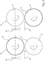
- the corrugated body 31 has a substantially cylindrical lateral surface 41.
- This lateral surface 41 may also be slightly convex or frustoconical. It is important, however, that over the lateral surface 41, a circumferential groove web 43 protrudes in the radial direction. The ribbed web 43 penetrates into the cover layer of the corrugated cardboard and deforms it without cutting it. This creates a crease line 13, such as in the FIG. 2 indicated.
- the mating body 33 has a cylindrical lateral surface 45.
- the lateral surface 45 can also be slightly convex.
- the geometry of the groove web 43 is shown enlarged in the detail X. It is clear that the groove web 43 has two flanks 45. The two flanks 45 enclose an angle alpha 1 of less than 90 °.
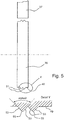
- FIG. 5 also schematically an expansion station 27 is shown. It should be pointed out again that the stretching of the corrugated cardboard takes place on the other side, as the grooves or the introduction of a score line 13 in the scoring station 25th
- the expansion station 27 comprises an expansion body 35 and a counter body 37. Formed on the lateral surface 49 of the expansion body 35 are two expansion webs 51 which project beyond the lateral surface 49 in the radial direction.
- the two expansion webs 51 are shown enlarged in detail Y.
- the expansion webs 51 each have two flanks 53. Between the flanks 53 there is a rounding 55 which has a radius of more than 2 mm. In practical experiments, it has proved to be advantageous if the radius of the rounding 55 is about 3 mm.
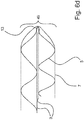
- FIG. 6 In the FIG. 6 is shown how a corrugated board is processed, first in the scoring station 25 and then in the stretching station 27th
- the corrugated cardboard processed on both sides is then folded in several steps. This process of folding is shown in further figures.
- FIGS. 6a to 6d is shown in various steps, as a crease line 13 and a Dehn Siemens is introduced into a corrugated cardboard.
- FIG. 6a is the first processing step, the introduction of a score line 13 is shown.
- the corrugated cardboard is stretched on the opposite second side.
- the stretched area (stretching area) is in the FIG. 6b designated by the reference numeral 49.
- the stretching region 49 is approximately as wide as the Width B of a slot 11 (see FIG. 2 ). It can also be about 1 to 2 mm wider than the width B.
- the corrugated and stretched corrugated cardboard according to the invention is folded.
- FIG. 6c an intermediate stage of folding is shown.
- the corrugated board is folded at an angle of about 80 ° along the score line 13.
- the stretched area 49 has already stretched a bit.
- FIG. 6d is shown by 180 ° folded corrugated cardboard.
- the two waves of Dehn Schemes 49 have disappeared almost completely. It results in a very clean folding and on the outside or the second side of the corrugated cardboard occur no cracks. This is due to the expansion of the invention upstream of the folding.
Landscapes
- Engineering & Computer Science (AREA)
- Mechanical Engineering (AREA)
- Machines For Manufacturing Corrugated Board In Mechanical Paper-Making Processes (AREA)
- Making Paper Articles (AREA)
Applications Claiming Priority (1)
| Application Number | Priority Date | Filing Date | Title |
|---|---|---|---|
| DE102016123374.9A DE102016123374A1 (de) | 2016-12-02 | 2016-12-02 | Vorrichtung und Verfahren zum Rillen von Wellpappe und Vollpappe |
Publications (2)
| Publication Number | Publication Date |
|---|---|
| EP3330070A2 true EP3330070A2 (fr) | 2018-06-06 |
| EP3330070A3 EP3330070A3 (fr) | 2018-08-29 |
Family
ID=60515227
Family Applications (1)
| Application Number | Title | Priority Date | Filing Date |
|---|---|---|---|
| EP17204457.0A Withdrawn EP3330070A3 (fr) | 2016-12-02 | 2017-11-29 | Dispositif et procédé destiné à rainurer du carton ondulé ou du carton homogène |
Country Status (2)
| Country | Link |
|---|---|
| EP (1) | EP3330070A3 (fr) |
| DE (1) | DE102016123374A1 (fr) |
Families Citing this family (2)
| Publication number | Priority date | Publication date | Assignee | Title |
|---|---|---|---|---|
| DE102024107249A1 (de) * | 2024-03-14 | 2025-09-18 | Knüppel Verpackung GmbH & Co. KG | Verfahren und Vorrichtung zur Verringerung der Biegesteifigkeit von Wellpappe und flexibilisierte Wellpappe |
| DE102024127390A1 (de) * | 2024-09-23 | 2026-03-26 | G. Kraft Maschinenbau Gesellschaft mit beschränkter Haftung | Bearbeitungseinrichtung zum Rillen einer Kartonbahn sowie Maschine zur Bearbeitung einer Kartonbahn sowie Verfahren zur Bearbeitung einer Kartonbahn |
Family Cites Families (10)
| Publication number | Priority date | Publication date | Assignee | Title |
|---|---|---|---|---|
| DE462229C (de) * | 1928-07-06 | Cartonnagenindustrie Ag F | Walzenriller fuer Pappen und Wellpappen | |
| DE248514C (fr) * | ||||
| DE29605073U1 (de) * | 1996-03-19 | 1996-05-23 | Essmann & Schaefer GmbH & Co. KG., 42369 Wuppertal | Rillwerkzeug zum Prägen von Faltrillen bei faltbaren Materialien |
| DE19838514C1 (de) * | 1998-08-25 | 2000-05-04 | Essmann & Schaefer | Rillwerkzeug zum Prägen von Faltrillen bei faltbaren Materialien |
| JP3717167B2 (ja) * | 2003-02-13 | 2005-11-16 | 株式会社イソワ | スリッタスコアラの制御方法 |
| US20090120263A1 (en) | 2007-11-12 | 2009-05-14 | Kabushiki Kaisha Isowa | Scorer apparatus for corrugated paperboard sheet |
| ITUD20110047A1 (it) * | 2011-03-30 | 2012-10-01 | Panotec Srl | Dispositivo di cordonatura e relativo metodo |
| AT512357B1 (de) * | 2012-01-12 | 2013-09-15 | Flatz Verpackungen Styropor Gmbh | Verfahren zur faltung von aus wellpappe bestehenden zuschnitten für die herstellung von faltschachteln und anlage hierfür |
| JP6247475B2 (ja) * | 2013-08-23 | 2017-12-13 | ザ・パック株式会社 | 段ボール包装材及び段ボール包装材の製造方法 |
| DE102013223854A1 (de) | 2013-09-09 | 2015-03-12 | Wilhelm B a h m ü l l e r Maschinenbau Präzisionswerkzeuge GmbH | Vorrichtung und Verfahren zum Rillen von Wellpappe und Vollpappe |
-
2016
- 2016-12-02 DE DE102016123374.9A patent/DE102016123374A1/de not_active Withdrawn
-
2017
- 2017-11-29 EP EP17204457.0A patent/EP3330070A3/fr not_active Withdrawn
Also Published As
| Publication number | Publication date |
|---|---|
| DE102016123374A1 (de) | 2018-06-07 |
| EP3330070A3 (fr) | 2018-08-29 |
Similar Documents
| Publication | Publication Date | Title |
|---|---|---|
| EP2845724B1 (fr) | Dispositif et procédé destiné à rainurer du carton ondulé ou du carton homogène | |
| EP2743071B1 (fr) | Procédé et dispositif de fabrication d'un produit de rembourrage et produit de rembourrage | |
| DE4400185B4 (de) | Verfahren und Vorrichtung zur Herstellung einer zwei Flansche und einen Steg aufweisenden Schiene für Hängedecken | |
| EP2700583B1 (fr) | Section destinée à fabriquer un emballage ou analogue ainsi que procédé de fabrication d'une telle section | |
| DE3614458A1 (de) | Verfahren und vorrichtung zum rillen | |
| EP3144133A1 (fr) | Dispositif destine au rainurage de feuilles de materiau | |
| EP2844572B1 (fr) | Emballage pour cigarettes | |
| DE10356037A1 (de) | Schneid-Vorrichtung | |
| EP3330070A2 (fr) | Dispositif et procédé destiné à rainurer du carton ondulé ou du carton homogène | |
| DE102015011399B4 (de) | Vorrichtung und Verfahren zum Rillen, Perforieren, Schneiden und Ritzen von flächigen Elementen | |
| EP0698454A1 (fr) | Procédé et dispositif ainsi que poinçon de découpe pour la réalisation de perforations de déchirement sur des produits en carton ondulé | |
| EP4234189B1 (fr) | Dispositif de maintien pour un dispositif de formage, procédé de formage d'un matériau d'emballage au moyen du dispositif de formage ainsi que machine de production dotée d'un tel dispositif de formage | |
| DD207357B5 (de) | Verfahren zur Herstellung von Erzeugnissen aus bahnfoermigem Material | |
| DE4319300A1 (de) | Verfahren zum Herstellen von mit ausgestanzten Laschen versehenen Blechteilen | |
| EP3228446B1 (fr) | Station de compression de lignes formant des rainures | |
| EP2228207B1 (fr) | Procédé de fabrication de lignes de pliage dans une feuille de matériau et dispositif d'exécution du procédé | |
| EP2311611A2 (fr) | Procédé et outil de production de pièces découpées de matériau en forme de bande | |
| DE102004001758B4 (de) | Vorrichtung zum Schneiden von bahnartigem Material sowie Verfahren zur Erzeugung von Querschnitten in einem bahnartigen Material | |
| WO2017207554A1 (fr) | Outil combiné d'estampage et d'entaillage/de coupe, et utilisation dudit outil | |
| DE60216738T2 (de) | Verfahren und werkzeug zum stanzen einer biegekante in einem verpackungsmaterial | |
| DE102008010588A1 (de) | Vorrichtung zur Herstellung eines Kantenschutzes | |
| EP4011574B1 (fr) | Machine à coller les fenêtres et dispositif de coupe à longueur et d'alimentation de matière | |
| EP4725687A2 (fr) | Dispositif de traitement destiné à rainurer une bande de carton ainsi que machine de traitement d'une bande de carton ainsi que procédé de traitement d'une bande de carton | |
| DE102018102718A1 (de) | Verfahren zum maschinellen Laserrillen von Nutzen sowie damit herstellbare dreidimensionale Struktur | |
| EP4461485A1 (fr) | Dispositif de fabrication de flans pour colliers de paquets de produits de l'industrie des cigarettes |
Legal Events
| Date | Code | Title | Description |
|---|---|---|---|
| PUAI | Public reference made under article 153(3) epc to a published international application that has entered the european phase |
Free format text: ORIGINAL CODE: 0009012 |
|
| AK | Designated contracting states |
Kind code of ref document: A2 Designated state(s): AL AT BE BG CH CY CZ DE DK EE ES FI FR GB GR HR HU IE IS IT LI LT LU LV MC MK MT NL NO PL PT RO RS SE SI SK SM TR |
|
| AX | Request for extension of the european patent |
Extension state: BA ME |
|
| PUAL | Search report despatched |
Free format text: ORIGINAL CODE: 0009013 |
|
| AK | Designated contracting states |
Kind code of ref document: A3 Designated state(s): AL AT BE BG CH CY CZ DE DK EE ES FI FR GB GR HR HU IE IS IT LI LT LU LV MC MK MT NL NO PL PT RO RS SE SI SK SM TR |
|
| AX | Request for extension of the european patent |
Extension state: BA ME |
|
| RIC1 | Information provided on ipc code assigned before grant |
Ipc: B31F 1/10 20060101AFI20180724BHEP Ipc: B31B 50/25 20170101ALI20180724BHEP |
|
| STAA | Information on the status of an ep patent application or granted ep patent |
Free format text: STATUS: THE APPLICATION IS DEEMED TO BE WITHDRAWN |
|
| 18D | Application deemed to be withdrawn |
Effective date: 20190301 |