EP4234391A1 - Anschlag für rudersteven mit gleitendem schaft und zugehörigem boot - Google Patents
Anschlag für rudersteven mit gleitendem schaft und zugehörigem boot Download PDFInfo
- Publication number
- EP4234391A1 EP4234391A1 EP23158285.9A EP23158285A EP4234391A1 EP 4234391 A1 EP4234391 A1 EP 4234391A1 EP 23158285 A EP23158285 A EP 23158285A EP 4234391 A1 EP4234391 A1 EP 4234391A1
- Authority
- EP
- European Patent Office
- Prior art keywords
- shaft
- base
- orifice
- rudder
- gudgeon
- Prior art date
- Legal status (The legal status is an assumption and is not a legal conclusion. Google has not performed a legal analysis and makes no representation as to the accuracy of the status listed.)
- Withdrawn
Links
- 241001125879 Gobio Species 0.000 claims description 59
- 230000001360 synchronised effect Effects 0.000 claims description 50
- 230000000295 complement effect Effects 0.000 claims description 6
- 241001125877 Gobio gobio Species 0.000 abstract 1
- -1 polyethylene terephthalate Polymers 0.000 description 3
- 229920000139 polyethylene terephthalate Polymers 0.000 description 3
- 239000005020 polyethylene terephthalate Substances 0.000 description 3
- 239000007787 solid Substances 0.000 description 3
- XAGFODPZIPBFFR-UHFFFAOYSA-N aluminium Chemical compound [Al] XAGFODPZIPBFFR-UHFFFAOYSA-N 0.000 description 2
- 229910052782 aluminium Inorganic materials 0.000 description 2
- 238000006073 displacement reaction Methods 0.000 description 2
- 230000003014 reinforcing effect Effects 0.000 description 2
- 239000011888 foil Substances 0.000 description 1
- 238000003780 insertion Methods 0.000 description 1
- 230000037431 insertion Effects 0.000 description 1
- 229910001220 stainless steel Inorganic materials 0.000 description 1
- 239000010935 stainless steel Substances 0.000 description 1
- XLYOFNOQVPJJNP-UHFFFAOYSA-N water Substances O XLYOFNOQVPJJNP-UHFFFAOYSA-N 0.000 description 1
Images



Classifications
-
- B—PERFORMING OPERATIONS; TRANSPORTING
- B63—SHIPS OR OTHER WATERBORNE VESSELS; RELATED EQUIPMENT
- B63H—MARINE PROPULSION OR STEERING
- B63H25/00—Steering; Slowing-down otherwise than by use of propulsive elements; Dynamic anchoring, i.e. positioning vessels by means of main or auxiliary propulsive elements
- B63H25/06—Steering by rudders
- B63H25/08—Steering gear
- B63H25/10—Steering gear with mechanical transmission
-
- B—PERFORMING OPERATIONS; TRANSPORTING
- B63—SHIPS OR OTHER WATERBORNE VESSELS; RELATED EQUIPMENT
- B63B—SHIPS OR OTHER WATERBORNE VESSELS; EQUIPMENT FOR SHIPPING
- B63B1/00—Hydrodynamic or hydrostatic features of hulls or of hydrofoils
- B63B1/16—Hydrodynamic or hydrostatic features of hulls or of hydrofoils deriving additional lift from hydrodynamic forces
- B63B1/24—Hydrodynamic or hydrostatic features of hulls or of hydrofoils deriving additional lift from hydrodynamic forces of hydrofoil type
- B63B1/242—Mounting, suspension of the foils
-
- B—PERFORMING OPERATIONS; TRANSPORTING
- B63—SHIPS OR OTHER WATERBORNE VESSELS; RELATED EQUIPMENT
- B63B—SHIPS OR OTHER WATERBORNE VESSELS; EQUIPMENT FOR SHIPPING
- B63B1/00—Hydrodynamic or hydrostatic features of hulls or of hydrofoils
- B63B1/16—Hydrodynamic or hydrostatic features of hulls or of hydrofoils deriving additional lift from hydrodynamic forces
- B63B1/24—Hydrodynamic or hydrostatic features of hulls or of hydrofoils deriving additional lift from hydrodynamic forces of hydrofoil type
- B63B1/28—Hydrodynamic or hydrostatic features of hulls or of hydrofoils deriving additional lift from hydrodynamic forces of hydrofoil type with movable hydrofoils
- B63B1/283—Hydrodynamic or hydrostatic features of hulls or of hydrofoils deriving additional lift from hydrodynamic forces of hydrofoil type with movable hydrofoils movable around a vertical axis, e.g. for steering
-
- B—PERFORMING OPERATIONS; TRANSPORTING
- B63—SHIPS OR OTHER WATERBORNE VESSELS; RELATED EQUIPMENT
- B63B—SHIPS OR OTHER WATERBORNE VESSELS; EQUIPMENT FOR SHIPPING
- B63B1/00—Hydrodynamic or hydrostatic features of hulls or of hydrofoils
- B63B1/16—Hydrodynamic or hydrostatic features of hulls or of hydrofoils deriving additional lift from hydrodynamic forces
- B63B1/24—Hydrodynamic or hydrostatic features of hulls or of hydrofoils deriving additional lift from hydrodynamic forces of hydrofoil type
- B63B1/28—Hydrodynamic or hydrostatic features of hulls or of hydrofoils deriving additional lift from hydrodynamic forces of hydrofoil type with movable hydrofoils
- B63B1/285—Hydrodynamic or hydrostatic features of hulls or of hydrofoils deriving additional lift from hydrodynamic forces of hydrofoil type with movable hydrofoils changing the angle of attack or the lift of the foil
-
- B—PERFORMING OPERATIONS; TRANSPORTING
- B63—SHIPS OR OTHER WATERBORNE VESSELS; RELATED EQUIPMENT
- B63B—SHIPS OR OTHER WATERBORNE VESSELS; EQUIPMENT FOR SHIPPING
- B63B1/00—Hydrodynamic or hydrostatic features of hulls or of hydrofoils
- B63B1/02—Hydrodynamic or hydrostatic features of hulls or of hydrofoils deriving lift mainly from water displacement
- B63B1/10—Hydrodynamic or hydrostatic features of hulls or of hydrofoils deriving lift mainly from water displacement with multiple hulls
- B63B1/12—Hydrodynamic or hydrostatic features of hulls or of hydrofoils deriving lift mainly from water displacement with multiple hulls the hulls being interconnected rigidly
- B63B1/121—Hydrodynamic or hydrostatic features of hulls or of hydrofoils deriving lift mainly from water displacement with multiple hulls the hulls being interconnected rigidly comprising two hulls
- B63B2001/123—Hydrodynamic or hydrostatic features of hulls or of hydrofoils deriving lift mainly from water displacement with multiple hulls the hulls being interconnected rigidly comprising two hulls interconnected by a plurality of beams, or the like members only
-
- B—PERFORMING OPERATIONS; TRANSPORTING
- B63—SHIPS OR OTHER WATERBORNE VESSELS; RELATED EQUIPMENT
- B63B—SHIPS OR OTHER WATERBORNE VESSELS; EQUIPMENT FOR SHIPPING
- B63B35/00—Vessels or similar floating structures specially adapted for specific purposes and not otherwise provided for
- B63B2035/009—Wind propelled vessels comprising arrangements, installations or devices specially adapted therefor, other than wind propulsion arrangements, installations, or devices, such as sails, running rigging, or the like, and other than sailboards or the like or related equipment
-
- B—PERFORMING OPERATIONS; TRANSPORTING
- B63—SHIPS OR OTHER WATERBORNE VESSELS; RELATED EQUIPMENT
- B63H—MARINE PROPULSION OR STEERING
- B63H25/00—Steering; Slowing-down otherwise than by use of propulsive elements; Dynamic anchoring, i.e. positioning vessels by means of main or auxiliary propulsive elements
- B63H25/02—Initiating means for steering, for slowing down, otherwise than by use of propulsive elements, or for dynamic anchoring
- B63H2025/024—Handle-bars; Posts for supporting handle-bars, e.g. adjustable posts
Definitions
- the present invention relates to a boat stem and an associated boat.
- a gudgeon ensures the connection between a corresponding rudder and the rest of the boat.
- a gudgeon is, for example, a simple piece of fittings attached to the rest of the boat, in which the corresponding pintle of the rudder fits.
- Such a femelot allows a solid connection between the rudder and the rest of the boat.
- the rudder is provided with a substantially horizontal plane at its base, such a plane helping the longitudinal stability of the boat.
- a gudgeon as described previously does not make it possible to modify the orientation of the rudder so as to allow such adjustment of the orientation of the plane at the base of the rudder.
- An object of the invention is therefore to provide a gudgeon adapted to provide a solid connection between a rudder and the rest of a boat, while allowing adjustment of the orientation of the corresponding rudder, in particular allowing the orientation of the a possible plane at the base of the rudder in relation to the horizontal.
- the invention relates to a femelot for a boat comprising a base adapted to be fixed to a hull of the boat and a shaft provided to be secured to a rudder of the boat, the base having an orifice, the shaft being movable in the orifice in a direction of translation.
- the invention further relates to a boat comprising at least one hull, at least one rudder and at least one gudgeon of the preceding type, the at least one gudgeon connecting one of the at least one hull and one of the at least one rudder, the base being fixed to the corresponding hull, the shaft being integral with the corresponding rudder.
- the boat can also have the following characteristic: the boat comprises a plurality of rudders and at least one upper gudgeon and one lower gudgeon per rudder, the upper gudgeon and the lower gudgeon connecting the corresponding rudder to a corresponding hull, the upper gudgeons being synchronized with each other.
- the longitudinal and transverse directions are understood relative to the normal direction of movement of the boat.
- the vertical direction corresponds to the direction perpendicular to the surface on which the boat is moving. Up and down are understood relative to the vertical direction.
- Boat 10, shown here on the figure 1 comprises at least one, here two, hulls 12 and at least one, here two, rudders 14.
- Boat 10 is here a sailboat.
- Boat 10 comprises as many rudders 14 as hulls 12.
- the boat 10 is, for example, of the “foiler” type in English “foil”, that is to say it comprises at least one submerged carrier plane 16 forming a bearing surface.
- the hull or hulls emerge at least partially from the water, in particular thanks to the bearing surface.
- Each hull 12 has a rear surface 18, also called a transom.
- the rear surface 18 extends substantially along a vertical and transverse plane.
- Each rudder 14 is connected to a corresponding hull 12 by at least one gudgeon, here by two gudgeons 20, 22.
- each rudder 14 is connected to a corresponding hull 12 by an upper gudgeon 20 and a lower gudgeon 22.
- the upper gudgeon 20 and the lower gudgeon 22 of the same rudder 14 are aligned in the vertical direction.
- the gudgeon(s) 20, 22 are, for example, fixed to the hull 12, so that the corresponding rudder 14 extends in a median position with respect to the hull 12.
- the gudgeon(s) 20, 22 are fixed to the hull 12, so that the corresponding rudder 14 extends in a position offset transversely with respect to the hull 12.
- Each rudder 14 has here, for example, a substantially horizontal plane at its base.
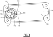
- gudgeon 110 An example of gudgeon 110 will now be described in more detail with regard to the figure 2 , 3 And 4 .
- the stem 110 includes a base 112 and a shaft 114.
- the gudgeon further comprises a synchronous pinion 116 and/or at least one cylindrical bearing 118.
- the gudgeon 110 comprises, for example, an axial stop 120.
- the base 112 is adapted to be fixed to a hull of the boat, more particularly to the rear surface of the hull.
- the base 112 comprises a base 122 intended to be in contact with the corresponding hull of the boat.
- the base 122 is substantially planar.
- the base 122 has a generally rectangular shape.
- the rectangular shape is oriented such that the shorter side extends vertically.
- the longer side runs transversely.
- the base 122 is provided with a recess 123.
- the base 122 has through holes, here tapped, 124 for fixing the base 122 to the corresponding shell, for example using screws.
- the holes 124 are, for example, arranged at the corners of the base 122.
- Base 112 further includes support 126.
- Bracket 126 serves as a guide for shaft 114 as will be described below.
- the support 126 projects in relation to the base 122, here perpendicular to the base 122.
- Support 126 is centered with respect to base 122 in the vertical direction and offset in the transverse direction.
- Support 126 has a distal end 127 opposite base 122.
- a reinforcing rib 128 connects support 126 to base 122.
- the reinforcing rib 128 extends along a transverse and longitudinal plane.
- the base 112 has an orifice 130.
- the orifice 130 here passes through the base 112, more particularly the entire support 126, in a main direction of extension.
- the orifice 130 is delimited by a side wall, the side wall being included in the support 126.
- the orifice 130 extends from the distal end 127 of the support 126 and opens into the base 122.
- Orifice 130 has a shoulder 132 at distal end 127.
- the orifice 130 has, for example, an invariance by rotation around a main axis of extension of the orifice.
- the orifice 130 has, for example, a cylindrical shape, here a straight cylinder, in sections.
- the orifice 130 comprises here, more particularly consists of, a front portion 134, a central portion 136 and the shoulder 132, in this order according to the main direction of extension.
- An intermediate shoulder 135 is formed between the front portion 134 and the central portion 136, more particularly by changing the size between the front portion 134 and the central portion 136.
- Each of the front portion, the middle portion and the rear shoulder has a straight cylinder shape.
- the front portion 134 has a diameter strictly greater than that of the central portion 136, which is strictly greater than the diameter of the shoulder 132.
- the orifice is at least partially threaded.
- the front portion 134 of the orifice that is to say the side wall delimiting the front portion 134, is at least partially threaded.
- the base 112 more particularly the support 126, has a window 138 opening into the orifice 130, more particularly at the level of the front portion 134.
- Window 138 passes through the side wall.
- the base 112 further has a secondary opening 140 adjacent to the orifice 130.
- the secondary opening 140 communicates with the orifice 130, here at the level of an overlap zone 142 between the orifice 130 and the secondary opening 140.
- the assembly formed by the secondary opening 140 and the orifice 130 has symmetry with respect to a plane of symmetry.
- the entire femelot has symmetry with respect to the plane of symmetry.
- the plane of symmetry is a plane perpendicular to the vertical.
- the secondary opening 140 communicates with the orifice 130 at the front portion 134 and the central portion 136.
- the secondary opening 140 extends parallel to the orifice 130.
- the main extension axis of the secondary opening 140 is parallel to the main extension axis of the orifice 130.
- the secondary opening 140 has an invariance by translation along the main direction of extension.
- the secondary opening 140 is, for example, here a cylinder having an oblong base as its base.
- the oblong shape has a preferred axis, corresponding to the axis along which the shape is elongated.
- the preferential axis is here included in the plane of symmetry.
- the stem includes at least one screw 143, here two screws, extending across the secondary opening 140, between opposite edges 144, 146 of the secondary opening 140.
- the or each screw 143 extends here in a direction perpendicular to the main direction of extension.
- the or each screw 143 here extends perpendicular to the plane of symmetry.
- the or each screw 143 extends in a tangential direction with respect to the orifice 130.
- the tangential direction corresponds to the local tangential direction of the wall delimiting the orifice 130 at a median of the overlap zone 142.
- the base 112 is here made of aluminum.
- the shaft 114 is designed to be integral with a rudder of the boat.
- Shaft 114 is movable in orifice 130 in a direction of translation.
- the direction of translation here is the main direction of extension.
- Shaft 114 extends primarily between an inner end 148 and an outer end 150.
- Shaft 114 is designed to be integral with the rudder at the outer end 150.
- the main axis of the shaft coincides with the main axis of the orifice 130.
- Shaft 114 extends partially into port 130.
- the shaft 114 is, for example, made of stainless steel.
- the shaft 114 comprises, here consists of, an inner portion 152, an intermediate portion 154 and an outer portion 156, in this order according to the direction of translation.
- Internal portion 152 extends within orifice 130.
- the internal portion 152 here has the shape of a right cylinder.
- the shaft 114 is at least partially threaded.
- the intermediate portion 154 has the shape of a right cylinder, having a diameter strictly greater than that of the internal portion 152.
- Outer portion 156 extends outside of orifice 130.
- the outer portion 156 has the shape of a right cylinder with two opposite flats.
- the two flats are opposed to each other in the transverse direction.
- Each flat extends horizontally.
- Each flat has an increasing dimension towards the outer end 150.
- the shaft 114 more particularly the outer portion 156, has a through hole 158.
- the through hole 158 extends in the vertical direction.
- the through hole 158 opens on either side at the level of the flats.
- Through hole 158 is threaded.
- the shaft 114 is provided with at least one, here two, aspherical bearings 160 at least partially inserted in the through hole 158, more particularly an upper bearing and a lower bearing.
- the or each bearing has an angular variation of plus or minus 2°.
- Each bearing 160 here has the shape of a hollow cylinder provided with a flange 162.
- the outer face of the hollow cylinder here has a complementary thread to the thread of the through hole 158.
- Each bearing is partially inserted, here screwed, into the through-hole 158, opposite one another.
- each bearing is inserted into the through hole 158 except for the collar.
- the collar here bears against the corresponding flat.
- the upper bearing is inserted, here screwed, into the through hole 158 from an upper side of the through hole, while the lower bearing is inserted, here screwed, into the through hole from a lower side of the through hole, opposite the upper side.
- the through hole 158 and the bearing(s) 160 do not have threads.
- the bearing(s) are, for example, glued in the through-hole.
- the hollow cylinder delimits an internal passage allowing the passage of a rudder shaft.
- the internal passage has, for example, an evolving profile allowing the precession of the rudder axis, then a parabolic profile emerging at the level of the flange 162.
- Each bearing is made of polyethylene terephthalate.
- the synchronous pinion 116 is integral with the shaft 114, more particularly with the internal portion 152 of the shaft 114, so that a rotation of the synchronous pinion 116 causes a translation of the shaft 114 according to the direction of translation.
- the synchronous pinion 116 extends into the hole 130 of the base 112, more particularly in the front portion 134 of the hole 130.
- the synchronous pinion 116 has a toothed cylindrical outer surface 164.
- the synchronous pinion 116 has a through hole delimited by a cylindrical inner surface, here tapped, 166.
- the cylindrical outer surface and the cylindrical inner surface are coaxial.
- the shaft 114 more particularly the inner portion 152 of the shaft, has a thread complementary to the inner surface of the synchronous pinion 116.
- the shaft 114 passes through the through hole of the synchronous pinion 116, the complementary thread cooperating with the internal threaded surface 166.
- the synchronous pinion 116 more particularly the outer toothed surface 164, extends partially opposite the window 138.
- the synchronous pinion 116 is accessible from the exterior of the base 112 through the window 138, more particularly for a user's hand or a tool.
- the synchronous pinion 116 is made of aluminum.
- the gudgeon comprises, for example, furthermore a synchronous belt capable of entering into rotation, the synchronous belt then driving the synchronous pinion 116 in rotation.
- the synchronous belt and the synchronous pinion 116 are integral in rotation.
- the rotational synchronous belt drives the pinion 116 in rotation, which in turn drives the shaft 114 in translation.
- the synchronous belt is extended in a loop, so that the belt can be driven continuously.
- the at least one cylindrical bearing 118 extends into the orifice 130, between the shaft 114 and the side wall of the orifice 130.
- the at least one cylindrical bearing 118 extends over the whole of the central portion 136 of the orifice.
- the at least one pad 118 is, for example, made of polyethylene terephthalate.
- the at least one cylindrical bearing 118 has an internal through passage, in which the shaft 114 partially extends.
- the at least one cylindrical bearing 118 partially surrounds the shaft.
- the at least one cylindrical bearing 118 has an invariance by rotation around an axis corresponding to the main axis of the orifice 130.
- the at least one cylindrical pad 118 extends between a distal end and a proximal end.
- the distal end extends here in contact with the shoulder 132.
- the proximal end is provided with an indexing element 168, here a shoulder.
- the indexing element 168 extends in contact with the intermediate shoulder 135.
- the at least one cylindrical bearing 118 has the general shape of a straight hollow cylinder provided with the indexing element.
- the hollow cylinder has an outer diameter equal to the diameter of the central portion 136 of the orifice 130.
- the hollow cylinder has an internal diameter equal to the diameter of the intermediate portion 154 of the shaft.
- the indexing element 168 abuts against the intermediate shoulder 135.
- the shaft 114 is in contact with the wall delimiting the internal through passage of the at least one cylindrical bearing 118.
- the at least one pad 118 is, for example, formed of a plurality of pads placed one after the other along the main axis of extension.
- the at least one bearing 118 makes it possible in particular to limit the wear of the shaft.
- the gudgeon does not include such a bearing, the shaft extending in direct contact with the orifice, the constriction of the orifice thus enclosing the shaft.
- the screw or screws are, for example, loosened at the time of assembly of the gudgeon, and in particular the insertion of the shaft 114 into the orifice 130.
- the synchronous pinion 116 is in contact against the proximal end of the at least one bearing 118.
- the axial stop 120 is in contact with the synchronous pinion 116 opposite the at least one bearing 118, here along the main axis, so that the synchronous pinion 116 is kept fixed in the direction of translation relative to base 112.
- the axial stop 120 is, for example, made of polyethylene terephthalate.
- the synchronous pinion 116 drives the shaft 114 by cooperation between the internally threaded cylindrical surface 166 and the complementary thread of the shaft 114.
- the synchronous pinion 116 being fixed with respect to the base 112 according to the direction of translation, the rotation of the synchronous pinion 116 causes a displacement in translation of the shaft 114 according to the direction of translation.
- the screw or screws are, for example, at least partially loosened during the translational movement of the shaft, then retightened after the translational movement of the shaft.
- Tightening the screws also makes it possible to take up any play that may be due to wear of the parts.
- Such a system therefore allows movement of the outer portion of the shaft 114, more particularly of the through-hole 158, through which a rudder shaft passes.
- all of the gudgeons 20, 22 is, for example, made according to the invention.
- the gudgeons are fixed to the corresponding hull, so that the corresponding rudder is in the desired alignment.
- the gudgeons of the right hull are fixed symmetrically to the gudgeons of the left hull.
- stems being symmetrical with respect to a horizontal plane of symmetry, the same model of stem is likely to be used on the right and on the left by turning the stem accordingly.
- the upper gudgeons 20 are synchronized with each other, so that any movement of the shaft of an upper gudgeon is carried out on the other or the other upper gudgeons.
- the upper stems are, for example, initialized, so that the extension of the upper stems 20 between the hull and the corresponding rudder is equal between the upper stems 20.
- the lower gudgeons 22 are also synchronized and initialized with each other.
- the lower gudgeons 22 are blocked in a given extension identical to each other.
- Such a configuration is particularly advantageous for synchronizing the rudders with each other.
- the boat comprises two hulls and two rudders, each rudder being connected to the corresponding hull by an upper gudgeon and a lower gudgeon, the upper gudgeon of a first of the rudders being synchronized with the lower gudgeon of the second of the rudders, the lower gudgeon of the first rudder being synchronized with the upper gudgeon of the second rudder.
- Such a configuration offers the possibility of putting more impact on one rudder, by removing it in the other, so as to add lift on one side of the boat and downforce on the other. This makes it possible in particular to exert a righting torque opposing the thrust in the sails.
- the gudgeon according to the invention therefore allows adjustment of the rudder by translation of the shaft relative to the base.
- the parts are linked together in a solid and robust way.
- Adjusting the screw by tightening also makes it possible to eliminate any residual play, so that there is no vibration phenomenon within the stem.
Landscapes
- Physics & Mathematics (AREA)
- Fluid Mechanics (AREA)
- Chemical & Material Sciences (AREA)
- Engineering & Computer Science (AREA)
- Combustion & Propulsion (AREA)
- Mechanical Engineering (AREA)
- Ocean & Marine Engineering (AREA)
- Manufacture And Refinement Of Metals (AREA)
- Transmission Devices (AREA)
- Measurement Of Force In General (AREA)
Applications Claiming Priority (1)
| Application Number | Priority Date | Filing Date | Title |
|---|---|---|---|
| FR2201648A FR3132898B1 (fr) | 2022-02-24 | 2022-02-24 | Fémelot à arbre coulissant et bateau associé |
Publications (1)
| Publication Number | Publication Date |
|---|---|
| EP4234391A1 true EP4234391A1 (de) | 2023-08-30 |
Family
ID=81448520
Family Applications (1)
| Application Number | Title | Priority Date | Filing Date |
|---|---|---|---|
| EP23158285.9A Withdrawn EP4234391A1 (de) | 2022-02-24 | 2023-02-23 | Anschlag für rudersteven mit gleitendem schaft und zugehörigem boot |
Country Status (2)
| Country | Link |
|---|---|
| EP (1) | EP4234391A1 (de) |
| FR (1) | FR3132898B1 (de) |
Citations (1)
| Publication number | Priority date | Publication date | Assignee | Title |
|---|---|---|---|---|
| JPS5231494A (en) * | 1975-06-17 | 1977-03-09 | Knoos Stellan P | Steering gear of ship that use hydraulic power servoomechanism |
-
2022
- 2022-02-24 FR FR2201648A patent/FR3132898B1/fr active Active
-
2023
- 2023-02-23 EP EP23158285.9A patent/EP4234391A1/de not_active Withdrawn
Patent Citations (1)
| Publication number | Priority date | Publication date | Assignee | Title |
|---|---|---|---|---|
| JPS5231494A (en) * | 1975-06-17 | 1977-03-09 | Knoos Stellan P | Steering gear of ship that use hydraulic power servoomechanism |
Non-Patent Citations (1)
| Title |
|---|
| ANONYMOUS: "The new DNA F1x A-class catamaran is unveiled! | International A-Division Catamaran Association", 30 March 2018 (2018-03-30), pages 1 - 13, XP093032283, Retrieved from the Internet <URL:https://www.a-cat.org/node/1204> [retrieved on 20230316] * |
Also Published As
| Publication number | Publication date |
|---|---|
| FR3132898A1 (fr) | 2023-08-25 |
| FR3132898B1 (fr) | 2024-02-23 |
Similar Documents
| Publication | Publication Date | Title |
|---|---|---|
| EP2939917A1 (de) | Modulare foil-vorrichtung | |
| FR2941395A1 (fr) | Mandrin porte-outil pour l'equipement d'une machine tournante. | |
| EP4234391A1 (de) | Anschlag für rudersteven mit gleitendem schaft und zugehörigem boot | |
| EP0098257B1 (de) | Drehbeschläge für Flügel wie Fensterläden, Türen oder dergleichen | |
| FR2823230A1 (fr) | Assemblage angulaire de lame | |
| EP0325074B1 (de) | Rollsegeleinrichtung mit parallel zum Mast angeordnetem Segelroller | |
| EP4100309B1 (de) | Vorrichtung zum verbinden zweier teile eines schiffsrumpfes und schiffsrumpf mit einer solchen vorrichtung | |
| EP2163703A1 (de) | Verbindung bzw. Gelenk zwischen zwei Hohlprofilen mit einstellbarem Winkel | |
| EP0609174B1 (de) | Vorrichtung zum Fräsen von Nuten | |
| EP2495458B1 (de) | Gefräster Schraubenkopf für die Befestigung von Zubehörteilen und Eisenwaren an einer Metallwand | |
| EP0992316B1 (de) | Handbetätigte Vorrichtung zur Richtigstellung der Position einer Elektrospindel bezüglich eines Trägers | |
| FR3122203A1 (fr) | Paumelle avec articulation deportee. | |
| FR2897120A1 (fr) | Pivot d'aube a angle de calage variable de turbomachine et dispositif de commande d'une telle aube | |
| WO2003084703A1 (fr) | Dispositif de bridage d'une plaquette de coupe amovible et outil support d'un tel dispositif | |
| FR3132129A1 (fr) | Boulon comprenant un écrou permettant d’exercer un effort de traction, outil de serrage permettant d’appliquer une précharge au boulon et procédé de serrage du boulon | |
| WO2012140379A1 (fr) | Quille de bateau escamotable | |
| FR2797657A1 (fr) | Systeme de volet comportant un volet roulant | |
| FR3120050A1 (fr) | Poignée pour un manche, du type manche d’aviron, et aviron comprenant une telle poignée | |
| FR2627740A1 (fr) | Dispositif pour le pliage et demontage d'un multicoque | |
| WO2018127631A1 (fr) | Mécanisme d'actionnement et de réglage quatre degrés de liberté d'un foil de bateau | |
| EP3835510A1 (de) | Handlaufvorrichtung für geländer | |
| FR2771374A1 (fr) | Dispositif de reglage des bras de levier d'un aviron sur la dame de nage d'une embarcation et aviron equipe d'un tel dispositif | |
| WO1999037930A1 (fr) | Charniere pour application en micromecanique | |
| EP4551453A1 (de) | Folienanordnung mit hohlem t-förmigen verbinder | |
| FR2697299A1 (fr) | Dispositif de raccord bout à bout de deux éléments profilés tubulaires de section au moins partiellement elliptique ou ovoïde. |
Legal Events
| Date | Code | Title | Description |
|---|---|---|---|
| PUAI | Public reference made under article 153(3) epc to a published international application that has entered the european phase |
Free format text: ORIGINAL CODE: 0009012 |
|
| STAA | Information on the status of an ep patent application or granted ep patent |
Free format text: STATUS: THE APPLICATION HAS BEEN PUBLISHED |
|
| AK | Designated contracting states |
Kind code of ref document: A1 Designated state(s): AL AT BE BG CH CY CZ DE DK EE ES FI FR GB GR HR HU IE IS IT LI LT LU LV MC ME MK MT NL NO PL PT RO RS SE SI SK SM TR |
|
| STAA | Information on the status of an ep patent application or granted ep patent |
Free format text: STATUS: REQUEST FOR EXAMINATION WAS MADE |
|
| 17P | Request for examination filed |
Effective date: 20240129 |
|
| RBV | Designated contracting states (corrected) |
Designated state(s): AL AT BE BG CH CY CZ DE DK EE ES FI FR GB GR HR HU IE IS IT LI LT LU LV MC ME MK MT NL NO PL PT RO RS SE SI SK SM TR |
|
| STAA | Information on the status of an ep patent application or granted ep patent |
Free format text: STATUS: THE APPLICATION HAS BEEN WITHDRAWN |
|
| 18W | Application withdrawn |
Effective date: 20250213 |