EP4234401A1 - Procédé d'atterrissage d'un système de cerf-volant et système de cerf-volant - Google Patents
Procédé d'atterrissage d'un système de cerf-volant et système de cerf-volant Download PDFInfo
- Publication number
- EP4234401A1 EP4234401A1 EP22159173.8A EP22159173A EP4234401A1 EP 4234401 A1 EP4234401 A1 EP 4234401A1 EP 22159173 A EP22159173 A EP 22159173A EP 4234401 A1 EP4234401 A1 EP 4234401A1
- Authority
- EP
- European Patent Office
- Prior art keywords
- kite
- partial
- gondola
- connection
- normal operation
- Prior art date
- Legal status (The legal status is an assumption and is not a legal conclusion. Google has not performed a legal analysis and makes no representation as to the accuracy of the status listed.)
- Withdrawn
Links
Images

Classifications
-
- B—PERFORMING OPERATIONS; TRANSPORTING
- B64—AIRCRAFT; AVIATION; COSMONAUTICS
- B64C—AEROPLANES; HELICOPTERS
- B64C31/00—Aircraft intended to be sustained without power plant; Powered hang-glider-type aircraft; Microlight-type aircraft
- B64C31/06—Kites
-
- F—MECHANICAL ENGINEERING; LIGHTING; HEATING; WEAPONS; BLASTING
- F03—MACHINES OR ENGINES FOR LIQUIDS; WIND, SPRING, OR WEIGHT MOTORS; PRODUCING MECHANICAL POWER OR A REACTIVE PROPULSIVE THRUST, NOT OTHERWISE PROVIDED FOR
- F03D—WIND MOTORS
- F03D5/00—Other wind motors
- F03D5/015—Other wind motors of the tethered aircraft type, e.g. kites, with traction and retraction of the tether
-
- F—MECHANICAL ENGINEERING; LIGHTING; HEATING; WEAPONS; BLASTING
- F05—INDEXING SCHEMES RELATING TO ENGINES OR PUMPS IN VARIOUS SUBCLASSES OF CLASSES F01-F04
- F05B—INDEXING SCHEME RELATING TO WIND, SPRING, WEIGHT, INERTIA OR LIKE MOTORS, TO MACHINES OR ENGINES FOR LIQUIDS COVERED BY SUBCLASSES F03B, F03D AND F03G
- F05B2240/00—Components
- F05B2240/90—Mounting on supporting structures or systems
- F05B2240/91—Mounting on supporting structures or systems on a stationary structure
- F05B2240/917—Mounting on supporting structures or systems on a stationary structure attached to cables
- F05B2240/9172—Mounting on supporting structures or systems on a stationary structure attached to cables of kite type with traction and retraction
Definitions
- the invention relates to a method for landing a kite system.
- the kite system comprises a kite and a gondola, with the kite being held on the gondola by a line boom.
- the gondola is held at an earth-bound articulation point via a traction cable.
- the invention also relates to a kite system.
- the kite can be moved along trajectories which are essentially perpendicular to the towing cable, and in this way exert a pulling force on the towing cable.
- Safety mechanisms are desirable for the operation of such a kite, with which the kite can still be controlled even if normal operation cannot be maintained. It could be the case, for example, that an operating state occurs in which the control fails and the kite can no longer be controlled in a targeted manner. If the kite exerts a high tensile force on the towing rope in this state, it may not be possible to retrieve the towing rope. A failure of the towing winch can also result in a situation in which it is impossible to retrieve the kite. In the event that the pull rope breaks, it's over EP 3 456 630 A1 , Known to bridge the breaking point with a capture device. Since the arresting device needs a certain distance in order to be able to absorb the high forces, part of the flight altitude that can be used in normal operation is lost.
- the invention is based on the object of presenting a method and a kite system so that the kite system can be landed reliably and safely even after normal operation has been abandoned. Based on the prior art mentioned, the object is achieved with the features of the independent claims. Advantageous embodiments are specified in the dependent claims.
- a sail surface of the kite is spanned by a first part kite and a second part kite.
- a connection between the first partial kite and the second partial kite located in the sail area is separated so that the kite changes to a different aerodynamic state and sinks to the ground with the gondola.
- the invention has recognized that the separation of a connection between the first partial kite and the second partial kite located in the sail surface opens up a way of quickly and reliably changing the aerodynamic state of the kite in such a way that the tensile force decreases.
- an aerodynamic state is established in which the lift exerted by the kite is no longer sufficient to keep the kite system in the air.
- the kite and associated gondola descend to the ground, with the kite acting as a parachute.
- the kite can act as a braking parachute in this state, so that the tension energy in the rope is dissipated when there are high rope loads without the rope experiencing a shock-like relief. Shock-like relief is undesirable because the traction cable can jump off the deflection pulleys at the ground station. If the tow rope is prevented from jumping off, the tow rope can still be pulled in despite the emergency landing system being triggered.
- the procedure is carried out in such a way that the kite rotates around the axis of the pull rope after it has been released, so that the kite sinks to the ground with little load but with the pull rope taut.
- the sail area is the surface of the kite along which the air flows when the kite is moved along flight paths.
- the sail surface may include an inner surface facing the nacelle and an outer surface facing away from the nacelle.
- the inner surface and the outer surface can be spaced apart and span an airfoil.
- the connection can extend in the direction of the airfoil, so that before the separation both the first part kite and the second part kite form a complete airfoil.
- the direction of the airfoil is called the longitudinal direction of the kite. Viewed in the transverse direction, the first part kite can be arranged next to the second part kite.
- a pivot point is grounded if it is not lifted off the ground by the pulling force of the kite.
- a ground-based pivot point can be firmly connected to the ground.
- ground-based pivot points on a ship, on a floating pontoon or on a mobile system on land are also possible.
- connection between the first partial kite and the second partial kite is formed in the sail area.
- the connection can form a continuous transition between the first part kite and the second part kite.
- the connection can be designed in such a way that the sail surface and/or the airfoil profile have no interruption in the area of the connection.
- the method can be carried out in such a way that the first part kite and the second part kite are completely separated from one another, so that after the separation within the sail area there is no longer any connection between the first and the second part kite.
- the first part kite and the second part kite are partially separated from one another, so that even after the separation there is still a connection between the first part kite and the second part kite in the sail area.
- the first part kite and the second part kite can be the same size so that the separation occurs in the middle of the kite. Two different sized dividing kites are also possible, so that the kite is separated off-centre.
- the kite can include more than two sub-kites.
- two of the participating kites each span a sail surface of the kite.
- the partial kites can be arranged next to one another in the transverse direction of the kite, so that a central partial kite is enclosed between two partial kites that are adjacent in the transverse direction.
- a connection can be formed between each two adjacent partial kites, which is separated when the method according to the invention is carried out. By dividing it into more than two part kites, even larger kites can be landed reliably.
- the separation of the partial kites can be triggered by a release element.
- the kite system can be set up in such a way that the triggering element triggers automatically if the normal operation of the kite system cannot be maintained.
- the trigger element can be triggered as a result of an exceptional event.
- the exceptional event as a result of which normal operation cannot be maintained, can be, for example, that a line of the line boom or the towing rope breaks or that an overload is acting on a line of the line boom or on the towing rope.
- the exceptional event can also consist in a state being determined in a control unit in which one or more operating parameters of the kite system are outside the normal range.
- the triggering element is triggered by an external intervention.
- the intervention can take place, for example, when an operator observes that the kite system is changing to an irregular state.
- the intervention can consist, for example, in the operator making an entry or actuating a switch.
- the triggering signal can be transmitted to the triggering element mechanically.
- the triggering element can be mechanically coupled to a cable, so that the triggering element triggers when the cable breaks or is overloaded.
- the triggering signal can also be a control signal that is transmitted electronically to the triggering element.
- the control signal can be transmitted to the triggering element by cable or via a radio link.
- the kite can have a predetermined separation point at which the connection between the first part kite and the second part kite is separated.
- the predetermined separation point can be provided with a safety device so that the connection between the first part kite and the second part kite is maintained as long as the safety device is active.
- the intended separation point can be designed in such a way that the connection between the first partial kite and the second partial kite under the influence of the aerodynamic forces acting on the sail surface forces is separated when the safety device is no longer active.
- the predetermined separation point can include a zip fastener through which the first part kite and the second part kite are connected to one another.
- the zipper can be kept in the closed state by the safety device. By releasing the securing device, a portion of the zipper can be released, allowing the zipper to open lengthwise. The opening of the zipper can proceed from the released portion in one direction or in both directions.
- the zipper is designed so that a number of teeth are absent or disengaged in the area where the securing device is located.
- the partial kites can be connected to a material at the intended separation point that is less tear-resistant than the adjacent material of the sail surface, so that the material of the intended separation point tears after the safety device has been released.
- a seam that comes loose lengthwise after the release of the safety device is also possible.
- a detonating cord that is ignited with the triggering element extends along the intended separation point. The fuse can weaken the material of the kite at the intended separation point so much that it tears.
- the intended separation point can be designed in such a way that it is separated after the safety device has been released under the influence of the aerodynamic forces occurring during normal operation of the kite system.
- the kite in order to separate the connection, is brought into a state in which higher aerodynamic forces act at the desired separation point than during normal operation of the kite system.
- the method can be carried out in such a way that the higher aerodynamic forces lead directly to a separation of the intended separation point.
- the intended separation point can be separated by releasing a safety device and the higher aerodynamic forces in combination.
- the line tree between the nacelle and the kite can comprise a plurality of lines via which the tensile forces are transmitted from the kite to the nacelle.
- the line boom can include lines designed as active control lines, the free length of which can be adjusted between the gondola and the kite. By operating the active steering lines, the kite can be controlled to move along the desired trajectories.
- the line boom can include lines designed as fixed lines with which sections of the kite are kept at a fixed distance from the gondola.
- the line boom can comprise lines designed as passive control lines, which extend between a first pivot point on the kite and a second pivot point on the kite and which are deflected between the pivot points on a pulley connected to the gondola.
- the fixed lines can be arranged in a central section of the kite in relation to the transverse direction.
- the steering lines can be located in a peripheral section of the kite.
- the passive control lines can be arranged in a section of the kite which lies between the central section and the peripheral section in relation to the transverse direction.
- the kite system can be set up in such a way that when the triggering element is triggered, a line of the line boom is severed.
- the line or a holding element connected to the line can be provided, for example, with a pyrocutter or with a compressed air shackle. If there is no longer any traction on the section of the kite in question, the section moves away from the gondola.
- the relevant movement of the kite can be used to release the safety device.
- a safety line can extend from the nacelle over the relevant section of the kite to the safety device, so that the movement in the kite exerts a tensile force on the safety device.
- the line that is severed with the release element can be a fixed line.
- the kite can be designed in such a way that a cavity surrounded by an outer skin is enclosed between the outer surface and the inner surface of the kite.
- an overpressure can be present in the cavity which is, for example, 50 mbar to 1000 mbar, preferably 100 mbar to 500 mbar higher than the ambient pressure.
- the overpressure can be fed by the airflow flowing along the sail surface when the kite is moving along flight paths.
- the kite may have an inlet port located between the outer surface and the inner surface of the kite.
- the inlet opening can be arranged in a front face of the kite that points in the direction of movement.
- an opening can be created in the outer skin of the kite, through which an overpressure present in the interior of the kite escapes.
- the escape of overpressure can change the aerodynamic state of the kite so that the drag force acting in the direction of the nacelle is reduced.
- the invention also relates to a kite system with a kite and a gondola.
- the kite is held to the gondola by a line boom.
- a sail surface of the kite is spanned by a first part kite and a second part kite.
- a connection between the first part kite and the second part kite is formed in the sail area.
- the kite system includes a release element for separating the connection, so that the kite changes to a different aerodynamic state after the connection has been separated and sinks to the ground with the gondola.
- the kite system may include a towing cable that extends between the nacelle and a ground-based pivot point.
- the pivot point can be part of a component of the kite system that is firmly connected to the ground.
- the kite system can be an element of a device for generating electrical energy.
- the device can include a generator which is driven by a traction cable winch. It is also possible that the kite system is connected to a pivot point of a ship, so that a propulsion force for the ship can be generated with the kite system.
- a pivot point of a ship is a ground-based pivot point within the meaning of the invention.
- the kite system can be developed with additional features that are described in connection with the method according to the invention.
- the method can be developed with further features that are described in connection with the kite system according to the invention.
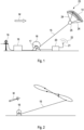
- An inventive device for generating electrical energy comprises according to 1 a kite system 23 according to the invention, which is connected to a towing cable winch 16 via a towing cable 15 .
- the kite system 23 includes a kite 14 which is connected to a gondola 25 via a line boom 24 .
- Coupled with the cable winch 16 is an electric power machine 17, which works as a generator in a first operating state and as a motor in a second operating state.
- the prime mover is connected to a public transmission grid 19 via an electrical power train 18, which includes a converter and a transformer, so that either electrical energy generated by the prime mover 17 can be fed into the transmission grid 19, or the prime mover 17 can also be fed from the transmission grid 19 extracted electrical energy can be operated as a motor.
- the device includes a Control unit 20, which is designed to control the interaction of the components of the device.
- the control unit 20 includes an antenna 21 so that control signals can be exchanged with the gondola 25 via a radio link 22 .
- control signals are sent from the control unit 20 to the nacelle 25 to control the trajectory of the kite 14 .
- the length of the control lines of the line boom 24 is changed, thereby influencing the direction of flight of the kite 14 .
- the kite 14 is guided along a figure eight that is essentially aligned transversely to the wind direction W. While the kite 14 follows the trajectory, a pulling force is exerted on the pull cable 15, with which the working machine 17 is driven via the pull cable winch 16. With the working machine 17 operated as a generator in this operating state, the mechanical energy is converted into electrical energy and fed into the public transmission network 19 via the power train 18 . It is also possible to store part of the energy generated in electrical form in an energy store of the power train 18 . In this way, electrical energy can be generated until the length of the traction cable 15 has been exhausted and the traction cable 15 has been completely released from the traction cable winch 16 . The traction cable 15 is then caught up with the working machine 17 operated as a motor before electrical energy can be generated again.
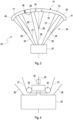
- the line tree 24 of the kite system 23 comprises according to 3 active control lines 26, passive control lines 27 and fixed lines 28, each posted on the gondola 25 and which branch out from nodes 29 into a plurality of ends attached to the kite 14 .
- the fixed lines 28 extend from an end in fixed connection with the pod 25 to a central portion of the kite 14.
- the active control lines 26, the length of which is adjustable, extend from the pod 25 to two peripheral portions of the kite 14.
- the passive control lines 27, which are deflected on the gondola 25 via rollers 30, are attached to the kite 14 between the fixed lines 28 and the active control lines 26.
- the direction of movement of the kite 14 can be controlled.
- the passive control lines 27 are carried along via the rollers 30, with the length of the passive control lines 27 from the kite 14 via the rollers 30 back to the kite 14 remaining unchanged.
- the kite 14 forms an airfoil that extends in the longitudinal direction from an in 3 visible end face 31 via an outer surface 32 and an inner surface 33 up to an in 3 not visible rear end extends. Inside the kite 14 there is a hollow space which is under overpressure during normal operation of the kite system.
- the kite 14 includes openings 34 formed in the end face 31, through which air can enter the interior and through which the overpressure is built up when the kite 14 is in motion.
- a zip fastener 36 is formed in the outer skin 35 of the kite 14 and, starting from the end face 31 , extends both over the outer surface 32 and over the inner surface 33 over the length of the airfoil profile to the rear end of the kite 14 .
- the Zipper 36 closed.
- the kite 14 can be separated into a first partial kite 40 and a second partial kite 41 by opening the zipper 36 .
- the zipper 36 connects the first part kite 40 and the second part kite 41 and forms a predetermined separation point between the first part kite 40 and the second part kite 41.
- the zipper 36 includes according to figure 5 a portion where a plurality of teeth are removed and which is secured with a securing device 37 .
- the securing device 37 extends over the zipper 36 and keeps it closed despite the missing teeth.
- the securing device 37 can be removed, with the result that the zipper 36 can be released lengthwise by forces acting transversely to the zipper 36.
- 6 1 shows a state of the zipper 36 just after the removal of the securing device 37, in which the zipper 36 starts to open.
- the zip fastener 36 can be opened over its entire length, as a result of which the first partial kite 41 and the second partial kite 41 are separated from one another.
- the release line 38 extends according to FIG 3 from the gondola 25 via a pivot point 39 formed on the kite 14 to the safety device 37. If the fixed line 28 is released, the central section of the kite 14 moves away from the gondola 25, so that the release line 38 is put under tension, whereby the Safety device 37 is released. As a result, the zipper 36 opens lengthwise so that the kite 14 separates into the first part kite 40 and the second part kite 41 . Opening the zipper 36 creates an opening in the outer skin 35 of the kite 14 through which the overpressure escapes. The first In this state, partial kite 40 and the second partial kite 41 each act as a parachute, on which the gondola 25 sinks to the ground.
- a pyrocutter 42 is arranged in a section of the fixed line 28 adjacent to the gondola 25 .
- the pyrocutter 42 can be triggered by an electrical signal, causing the mooring line 28 to be severed.
- the pyrocutter 42 forms a triggering element within the meaning of the invention.
- the electrical signal for triggering the pyrocutter 42 can be given by the control unit 20 and generated when an exceptional event occurs, as a result of which the kite system can no longer be operated in normal operation.
- the central portion of the kite 14 rises away from the nacelle 25, thereby putting the release line 38 under tension.
- the safety device 37 is removed and the zipper 36 is opened, so that the gondola with the two partial kites 40, 41 acting as a parachute sinks to the ground.
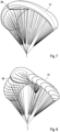
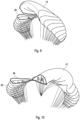
- FIG. 7-10 The process in question is in Figures 7-10 shown.
- the kite system 23 is shown in normal operation.
- the mooring line 28 has been severed so that the central section of the kite 14 rises and the securing device 37 is released from the zipper 36.
- the zipper 36 is partially released.
- the two partial kites 40, 41 are separated from one another. With the escape of the excess pressure from the interior, the partial kites 40, 41 lose their aerodynamic profile and only act as a parachute.
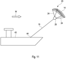
- kite system 23 according to the invention is used to generate a propulsion force for a ship 43 .
Landscapes
- Engineering & Computer Science (AREA)
- Aviation & Aerospace Engineering (AREA)
- Life Sciences & Earth Sciences (AREA)
- Sustainable Development (AREA)
- Sustainable Energy (AREA)
- Chemical & Material Sciences (AREA)
- Combustion & Propulsion (AREA)
- Mechanical Engineering (AREA)
- General Engineering & Computer Science (AREA)
- Toys (AREA)
- Wind Motors (AREA)
Priority Applications (8)
| Application Number | Priority Date | Filing Date | Title |
|---|---|---|---|
| EP22159173.8A EP4234401A1 (fr) | 2022-02-28 | 2022-02-28 | Procédé d'atterrissage d'un système de cerf-volant et système de cerf-volant |
| AU2023225089A AU2023225089A1 (en) | 2022-02-28 | 2023-02-21 | Method for landing a kite system, and kite system |
| EP23707038.8A EP4486648A1 (fr) | 2022-02-28 | 2023-02-21 | Procédé d'atterrissage d'un système de cerf-volant et système de cerf-volant |
| US18/841,892 US12552532B2 (en) | 2022-02-28 | 2023-02-21 | Method for landing a kite system, and kite system |
| CN202380023549.XA CN118695993A (zh) | 2022-02-28 | 2023-02-21 | 用于降落风筝系统的方法和风筝系统 |
| JP2024544864A JP2025507516A (ja) | 2022-02-28 | 2023-02-21 | 凧システムを着陸させるための方法、および凧システム |
| PCT/EP2023/054290 WO2023161216A1 (fr) | 2022-02-28 | 2023-02-21 | Procédé d'atterrissage d'un système de cerf-volant et système de cerf-volant |
| TW112106692A TW202415591A (zh) | 2022-02-28 | 2023-02-23 | 降落風帆系統的方法及風帆系統 |
Applications Claiming Priority (1)
| Application Number | Priority Date | Filing Date | Title |
|---|---|---|---|
| EP22159173.8A EP4234401A1 (fr) | 2022-02-28 | 2022-02-28 | Procédé d'atterrissage d'un système de cerf-volant et système de cerf-volant |
Publications (1)
| Publication Number | Publication Date |
|---|---|
| EP4234401A1 true EP4234401A1 (fr) | 2023-08-30 |
Family
ID=80595569
Family Applications (2)
| Application Number | Title | Priority Date | Filing Date |
|---|---|---|---|
| EP22159173.8A Withdrawn EP4234401A1 (fr) | 2022-02-28 | 2022-02-28 | Procédé d'atterrissage d'un système de cerf-volant et système de cerf-volant |
| EP23707038.8A Pending EP4486648A1 (fr) | 2022-02-28 | 2023-02-21 | Procédé d'atterrissage d'un système de cerf-volant et système de cerf-volant |
Family Applications After (1)
| Application Number | Title | Priority Date | Filing Date |
|---|---|---|---|
| EP23707038.8A Pending EP4486648A1 (fr) | 2022-02-28 | 2023-02-21 | Procédé d'atterrissage d'un système de cerf-volant et système de cerf-volant |
Country Status (7)
| Country | Link |
|---|---|
| US (1) | US12552532B2 (fr) |
| EP (2) | EP4234401A1 (fr) |
| JP (1) | JP2025507516A (fr) |
| CN (1) | CN118695993A (fr) |
| AU (1) | AU2023225089A1 (fr) |
| TW (1) | TW202415591A (fr) |
| WO (1) | WO2023161216A1 (fr) |
Citations (4)
| Publication number | Priority date | Publication date | Assignee | Title |
|---|---|---|---|---|
| US7287481B1 (en) * | 2006-08-15 | 2007-10-30 | Skysails Gmbh & Co. Kg | Launch and retrieval arrangement for an aerodynamic profile element and an aerodynamic profile element |
| DE202011107010U1 (de) * | 2011-10-20 | 2012-02-13 | Heiko Herrmann | Kiteverlängerung |
| CN207550464U (zh) * | 2017-12-14 | 2018-06-29 | 浙江海洋大学 | 一种船用筝帆及船舶 |
| EP3456630A1 (fr) | 2017-09-15 | 2019-03-20 | SkySails Power GmbH | Système d'aile |
Family Cites Families (8)
| Publication number | Priority date | Publication date | Assignee | Title |
|---|---|---|---|---|
| US3534931A (en) * | 1968-03-28 | 1970-10-20 | Rogallo Francis J | Variable area flexible wings |
| GB1503738A (en) * | 1975-03-05 | 1978-03-15 | Irvin Ltd | Parachutes |
| US6845948B2 (en) * | 2002-02-08 | 2005-01-25 | Paul J. Thomas | Adaptable kite/airfoil |
| DE102004018814A1 (de) * | 2004-04-19 | 2005-11-03 | Skysails Gmbh | Setzsystem für ein ausfliegendes drachenartiges Windangriffselement bei einem Wasserfahrzeug mit Windantrieb |
| SG194257A1 (en) * | 2012-04-26 | 2013-11-29 | Yik Hei Sia | Power generating windbags and water-bags |
| US10336412B2 (en) * | 2015-10-01 | 2019-07-02 | Clayton Morris | Adjustable area kite or wing |
| US9908609B1 (en) * | 2016-06-02 | 2018-03-06 | X Development Llc | Explosive strip for venting gas from a balloon |
| US11084564B1 (en) * | 2020-02-03 | 2021-08-10 | Space Perspective Inc. | Aerospace vehicle system and method of operation |
-
2022
- 2022-02-28 EP EP22159173.8A patent/EP4234401A1/fr not_active Withdrawn
-
2023
- 2023-02-21 EP EP23707038.8A patent/EP4486648A1/fr active Pending
- 2023-02-21 US US18/841,892 patent/US12552532B2/en active Active
- 2023-02-21 WO PCT/EP2023/054290 patent/WO2023161216A1/fr not_active Ceased
- 2023-02-21 CN CN202380023549.XA patent/CN118695993A/zh active Pending
- 2023-02-21 JP JP2024544864A patent/JP2025507516A/ja active Pending
- 2023-02-21 AU AU2023225089A patent/AU2023225089A1/en active Pending
- 2023-02-23 TW TW112106692A patent/TW202415591A/zh unknown
Patent Citations (4)
| Publication number | Priority date | Publication date | Assignee | Title |
|---|---|---|---|---|
| US7287481B1 (en) * | 2006-08-15 | 2007-10-30 | Skysails Gmbh & Co. Kg | Launch and retrieval arrangement for an aerodynamic profile element and an aerodynamic profile element |
| DE202011107010U1 (de) * | 2011-10-20 | 2012-02-13 | Heiko Herrmann | Kiteverlängerung |
| EP3456630A1 (fr) | 2017-09-15 | 2019-03-20 | SkySails Power GmbH | Système d'aile |
| CN207550464U (zh) * | 2017-12-14 | 2018-06-29 | 浙江海洋大学 | 一种船用筝帆及船舶 |
Also Published As
| Publication number | Publication date |
|---|---|
| JP2025507516A (ja) | 2025-03-21 |
| WO2023161216A1 (fr) | 2023-08-31 |
| TW202415591A (zh) | 2024-04-16 |
| US20250171140A1 (en) | 2025-05-29 |
| AU2023225089A1 (en) | 2024-08-08 |
| CN118695993A (zh) | 2024-09-24 |
| US12552532B2 (en) | 2026-02-17 |
| EP4486648A1 (fr) | 2025-01-08 |
Similar Documents
| Publication | Publication Date | Title |
|---|---|---|
| DE10007430B4 (de) | Großflächige Fallschirmvorrichtung mit einem Reißnahtstoßdämpfer zur Steuerung des ersten Entfaltens | |
| DE102011050630B4 (de) | Rettungsverfahren und Rettungsvorrichtung | |
| EP1747990A2 (fr) | Aéronef avec un système d'atterrissage de secours | |
| DE10241585B4 (de) | Lastengleitfallschirm-System | |
| EP2729357B1 (fr) | Procédé et dispositif de commande d'un élément volant amarré | |
| EP1359091B1 (fr) | Système de largage de charges avec parachute | |
| DE3406693C2 (fr) | ||
| DE2544989C3 (de) | Vorrichtung zum Abtrennen der Aufziehvorrichtung eines Fallschirmes | |
| EP4234401A1 (fr) | Procédé d'atterrissage d'un système de cerf-volant et système de cerf-volant | |
| DE2356922A1 (de) | Netzanordnung zum abfangen von flugzeugen | |
| WO2017013205A1 (fr) | Unité de coupe de câble pour un treuil, système de coupe de câble pour un treuil et procédé pour faire fonctionner une unité de coupe de câble destinée à un treuil | |
| EP3456630B1 (fr) | Système d'aile | |
| EP4486642B1 (fr) | Système de cerf-volant | |
| DE2233901C3 (de) | Sicherheitsgurtsystem für Fahrzeuge, insbesondere Kraftfahrzeuge | |
| DE102011108348A1 (de) | Zugmittel, Gassackmodul mit Zugmittel und Verfahren zur Herstellung eines Zugmittels | |
| DE102008004439B4 (de) | Pyrotechnische Trennvorrichtung und Fallschirmsystem mit einer solchen | |
| EP1066196A1 (fr) | Procede pour l'ouverture d'un parachute de sauvetage et systeme de parachute muni d'un parachute actionne selon ce procede | |
| EP4467451A1 (fr) | Système de kit et procédé de fonctionnement d'un système de kit | |
| EP3453608A1 (fr) | Procédé et système d'arrimage d'un élément soumis à l'action du vent | |
| DE202024101890U1 (de) | Trennvorrichtung zur Trennung einer Leitungsführungseinheit von einem Anschluss und System bestehend aus einer Trennvorrichtung und einer Leitungsführungseinheit | |
| DE3429196A1 (de) | Verfahren zum verlegen eines zwischen weit auseinanderliegenden auflagern wie freileitungs- oder seilbahnmasten laufenden seils, kabels od.dgl. | |
| DE1935255A1 (de) | Doppelt wirksame Fallschirmanordnung | |
| DE102024127361A1 (de) | Sicherheitsvorrichtung und Verfahren für Fallschirmspringer beim Abspringen | |
| DE202024001325U1 (de) | Schleppklinke | |
| WO2025180768A1 (fr) | Procédé de démarrage d'un système de cerf-volant, unité de commande pour un dispositif de cerf-volant, et dispositif de cerf-volant |
Legal Events
| Date | Code | Title | Description |
|---|---|---|---|
| PUAI | Public reference made under article 153(3) epc to a published international application that has entered the european phase |
Free format text: ORIGINAL CODE: 0009012 |
|
| STAA | Information on the status of an ep patent application or granted ep patent |
Free format text: STATUS: THE APPLICATION HAS BEEN PUBLISHED |
|
| AK | Designated contracting states |
Kind code of ref document: A1 Designated state(s): AL AT BE BG CH CY CZ DE DK EE ES FI FR GB GR HR HU IE IS IT LI LT LU LV MC MK MT NL NO PL PT RO RS SE SI SK SM TR |
|
| STAA | Information on the status of an ep patent application or granted ep patent |
Free format text: STATUS: THE APPLICATION IS DEEMED TO BE WITHDRAWN |
|
| 18D | Application deemed to be withdrawn |
Effective date: 20240301 |