EP4467451A1 - Système de kit et procédé de fonctionnement d'un système de kit - Google Patents
Système de kit et procédé de fonctionnement d'un système de kit Download PDFInfo
- Publication number
- EP4467451A1 EP4467451A1 EP23174818.7A EP23174818A EP4467451A1 EP 4467451 A1 EP4467451 A1 EP 4467451A1 EP 23174818 A EP23174818 A EP 23174818A EP 4467451 A1 EP4467451 A1 EP 4467451A1
- Authority
- EP
- European Patent Office
- Prior art keywords
- kite
- branching block
- tension cord
- gondola
- point
- Prior art date
- Legal status (The legal status is an assumption and is not a legal conclusion. Google has not performed a legal analysis and makes no representation as to the accuracy of the status listed.)
- Withdrawn
Links
Images




Classifications
-
- B—PERFORMING OPERATIONS; TRANSPORTING
- B64—AIRCRAFT; AVIATION; COSMONAUTICS
- B64C—AEROPLANES; HELICOPTERS
- B64C31/00—Aircraft intended to be sustained without power plant; Powered hang-glider-type aircraft; Microlight-type aircraft
- B64C31/06—Kites
-
- B—PERFORMING OPERATIONS; TRANSPORTING
- B63—SHIPS OR OTHER WATERBORNE VESSELS; RELATED EQUIPMENT
- B63H—MARINE PROPULSION OR STEERING
- B63H9/00—Marine propulsion provided directly by wind power
- B63H9/04—Marine propulsion provided directly by wind power using sails or like wind-catching surfaces
- B63H9/06—Types of sail; Constructional features of sails; Arrangements thereof on vessels
- B63H9/069—Kite-sails for vessels
- B63H9/072—Control arrangements, e.g. for launching or recovery
-
- F—MECHANICAL ENGINEERING; LIGHTING; HEATING; WEAPONS; BLASTING
- F03—MACHINES OR ENGINES FOR LIQUIDS; WIND, SPRING, OR WEIGHT MOTORS; PRODUCING MECHANICAL POWER OR A REACTIVE PROPULSIVE THRUST, NOT OTHERWISE PROVIDED FOR
- F03D—WIND MOTORS
- F03D5/00—Other wind motors
- F03D5/015—Other wind motors of the tethered aircraft type, e.g. kites, with traction and retraction of the tether
-
- Y—GENERAL TAGGING OF NEW TECHNOLOGICAL DEVELOPMENTS; GENERAL TAGGING OF CROSS-SECTIONAL TECHNOLOGIES SPANNING OVER SEVERAL SECTIONS OF THE IPC; TECHNICAL SUBJECTS COVERED BY FORMER USPC CROSS-REFERENCE ART COLLECTIONS [XRACs] AND DIGESTS
- Y02—TECHNOLOGIES OR APPLICATIONS FOR MITIGATION OR ADAPTATION AGAINST CLIMATE CHANGE
- Y02E—REDUCTION OF GREENHOUSE GAS [GHG] EMISSIONS, RELATED TO ENERGY GENERATION, TRANSMISSION OR DISTRIBUTION
- Y02E10/00—Energy generation through renewable energy sources
- Y02E10/70—Wind energy
Definitions
- the invention relates to a kite system and a method for operating a kite system.
- a kite that is held by a tow rope can be moved along flight paths that are essentially perpendicular to the tow rope by appropriately adjusting the aerodynamic properties. As the kite moves along the flight paths, a pulling force is exerted on the tow rope.
- the pulling force can be used, for example, to generate electrical energy or as propulsion power for a ship.
- the kite In normal operation of the kite system, where a high pulling force is desired, the kite is controlled so that it moves within a wind window within which the wind exerts a strong force on the kite.
- the kite it has been common practice to control the kite to the edge of the wind window for retrieval, where the force exerted by the wind on the kite is significantly smaller.
- WO 2007/112 993 A1 This is associated with a loss of time because the kite must first travel the distance to the edge of the wind window before it can be retrieved.
- the invention is based on the object of presenting a kite system and a method for operating a kite system with which these disadvantages are avoided.
- the object is achieved with the features of the independent claims.
- Advantageous embodiments are specified in the subclaims.
- a kite system comprises a kite, a gondola and a line tree.
- the kite is connected to the gondola via the line tree.
- the line tree comprises a branching block, which is connected to the gondola via a control cable.
- the line tree comprises a first tension cord extending between the branch block and a first pivot point of the kite.
- the line tree comprises a second tension cord extending between the branch block and a second pivot point of the kite.
- the kite system is equipped with a control mechanism to change the length of the control cable between the gondola and the branch block.
- the kite system is equipped with a trim mechanism to change the length of the first tension cord between the branch block and the first pivot point.
- the invention proposes coupling a trim mechanism to the control mechanism of the kite system.
- the control mechanism can be designed to influence the direction of flight of the kite.
- the trim mechanism can be designed to influence the angle of attack of the kite.
- the coupling between the control mechanism and the trim mechanism makes it possible to change the angle of attack while at the same time maintaining the ability to control it. For example, the kite can be brought into a different angle of attack and controlled in this state along predetermined flight paths without the control mechanism having to be adjusted to the changed angle of attack.
- the kite system may comprise a traction cable extending from the gondola to a force receiving point on the ground.
- the force receiving point may be arranged on a ship, for example, so that a traction force acting on the force receiving point acts as a propulsion force for the ship.
- the traction force of the kite acts via the force receiving point on a generator to generate electrical energy.
- the kite may extend from the force receiving point while generating electrical energy so that the generator is driven by a movement of the tow rope. If the kite system is used to operate a ship, the distance between the gondola and the power absorption point can remain constant.
- the current flight direction of the kite can form a right angle with the direction of the pull rope, i.e. the direction in which the pull rope pulls on the gondola.
- the control cable can be arranged in a plane that is orthogonal to the current flight direction. Operating the control cable can trigger a rolling movement of the kite, with which the kite as a whole or a section of the kite is pivoted around an axis parallel to the flight direction. Such a rolling movement of the kite results in the kite's flight path bending, i.e. the kite flying in a curve. Flying through the curve is accompanied by a rotation of the kite around the direction of the pull rope.
- the kite system comprises a first control cable and a second control cable, the first control cable acting on a different section of the kite than the second control cable.
- Each of the control cables can have the features mentioned of the one control cable.
- the first control cable and the second control cable can be arranged on two sides of a longitudinal center plane of the kite spanned by the pull rope and the direction of flight.
- the control mechanism can be set up such that the first control cable and the second control cable are coupled to one another.
- the coupling can be designed such that the first control cable is shortened when the second control cable is lengthened, and vice versa.
- the kite system can be set up so that the kite performs a rolling movement.
- the trim mechanism can be designed to trigger a pitching movement of the kite about a pitch axis.
- a pitching movement is a movement in which the kite or part of the kite is rotated about a pitch axis that forms a right angle with the direction of flight.
- the pitch axis can also form a right angle with the direction of pull, i.e. the direction in which tensile forces are transmitted between the kite and the branching block. Due to the curved shape of the kite, the local direction of pull depends on the distance to the longitudinal center plane of the kite. The angle between the direction of the pull rope and the local direction of pull becomes larger the greater the distance between the pivot point and the longitudinal center plane.
- the pitching movement therefore refers to a local pitch axis that applies to the longitudinal plane of the kite, within which the pivot points involved in the pitching movement are arranged.
- the pitch axis may be at a constant distance from the branch block.
- the kite system may comprise a line extending between a pivot point located at the pitch axis and the branch block.
- the line may form a fixed length connection between the branch block and the pivot point of the kite.
- the trim mechanism may be designed to change both the length of the first tension cord between the branch block and the first pivot point and the length of the second tension cord between the branch block and the second pivot point. If the first pivot point and the second pivot point are located on two sides of the pitch axis, a pitching movement can be initiated by lengthening the first tension cord and shortening the second tension cord or vice versa. There may be a line extending between the branch block and a third pivot point of the Kite.
- the first articulation point, the second articulation point and the third articulation point can form a set of articulation points.
- Several articulation points form a set if they are arranged in a plane that is parallel to a plane that is spanned by the current flight direction and the local pulling direction.
- the articulation points of a set of articulation points can be controlled in a coordinated manner with the trimming device in order to trigger the pitching movement of the kite.
- the first tension cord and the second tension cord can be mechanically coupled to
- a set of articulation points comprises a first articulation point and a second articulation point, wherein the first articulation point is connected to the branching block via a first tension cord, wherein the second articulation point is connected to the branching block via a second tension cord, wherein the first articulation point and the second articulation point are arranged on one side of the pitch axis, and wherein the second articulation point is at a greater distance from the pitch axis than the first articulation point.
- the trimming device can be configured such that the first tension cord and the second tension cord are actuated in a coordinated manner, wherein the actuation path of the first tension cord is smaller than the actuation path of the second tension cord. In this way, a pitching movement of the kite can be triggered.
- the kite system may be designed such that a set of articulation points comprises one or more articulation points arranged on one side of the pitch axis and one or more articulation points arranged on the other side of the pitch axis. In one embodiment, at least three articulation points are arranged on one side of the pitch axis.
- the pitch axis may be arranged adjacent to the pressure point of the kite.
- the pressure point viewed in the longitudinal direction of the kite may be Distance between the pressure point of the kite and the pitch axis should be less than 20%, preferably less than 10%, more preferably less than 5% of the distance between the front edge of the kite and the rear edge of the kite in the relevant section of the kite. If the pitch axis is located near the pressure point, only a small amount of force is required to operate the trim mechanism. This is particularly advantageous if the energy required to operate the trim mechanism is provided from the nacelle.
- the invention also encompasses embodiments in which all tension cords are attached in front of the pitch axis or behind the pitch axis. In these embodiments, a higher force is required to actuate the trim mechanism.
- the coordinated control of the articulation points of a set of articulation points with the trimming mechanism can be carried out in such a way that the geometric shape of the kite is maintained within the longitudinal plane of the kite.
- the longitudinal plane is spanned by the set of articulation points and the local direction of pull. This can be achieved by ensuring that the actuation path over which the articulation points are moved during the trimming process is essentially proportional to the distance that the respective articulation point has from the pitch axis.
- the coordinated control of the articulation points of a set of articulation points with the trimming mechanism is carried out in such a way that the geometric shape of the kite within the set of articulation points is changed by the trimming process. This can be achieved by ensuring that there is a significant deviation from the proportional relationship between the articulation points of the set of articulation points. For example, the trimming process can give the kite a more curved shape.
- kite develops a high lift force despite a lower flight speed. It is also possible to give the kite a less curved shape so that flight resistance is reduced and a higher flight speed is possible.
- the position of the kite changes relative to the position of the gondola. If the movement is considered within the reference system of the kite, i.e. a coordinate system within which the position of the kite remains unchanged, the movement can be described as a pivoting movement of the gondola relative to the kite.
- the adjustment range of the trim mechanism can be so large that the pivoting movement extends over an angle of at least 20°, preferably an angle of at least 30°, more preferably an angle of at least 45°.
- the center of the pivoting movement corresponds to the pitch axis.
- the length of a pull cord can be changed by pulling in or releasing an actuating line.
- the coordinated control of several pull cords of a kite system can be achieved by assigning an actuating line to each pull cord and adjusting the length of the actuating lines separately. For example, each actuating line can be assigned its own actuator.
- a mechanical coupling between a first traction cord and a second traction cord is also possible, so that the length of the first traction cord cannot be changed without simultaneously changing the length of the second traction cord.
- This can be achieved, for example, by leading an actuating line of a first traction cord and an actuating line of a second traction cord to a common actuator, so that when the actuator is actuated, both actuating lines be changed in length.
- the actuation path of the first actuation line can be the same as the actuation path of the second actuation line or can differ from the actuation path of the second actuation line.
- the latter can be achieved, for example, by driving the actuation line via a shaft with a stepped diameter and by guiding the first actuation line over a different diameter of the shaft than the second actuation line. If there are more than two actuation lines, the same procedure can be followed.
- the trim mechanism can couple two tension cords that belong to one set of articulation points. It is also possible for tension cords that belong to several sets of articulation points to be coupled together. In one embodiment, the trim mechanism couples two tension cords that are arranged on two sides of a longitudinal center plane of the kite.
- the trim mechanism may comprise a single control line that operates a first pulley and a second pulley.
- the control line may be guided over a pulley of the first pulley and over a pulley of the second pulley, so that the length of the first pulley and the second pulley are changed by pulling in or releasing the control line. If there are more than two pulleys, the same procedure can be used.
- An operating line of the trim mechanism which is guided over a roller, can be equipped with a travel limiter so that the operating line no longer runs over the roller as soon as the travel limiter hits the roller. In this way, by operating a single operating line, different Effects are triggered. Equipping an actuating line with a travel limiter can be particularly useful when several traction cords are coupled to an actuating line. These can be traction cords from one set of pivot points or traction cords from several sets of pivot points.
- the kite system may comprise a first set of articulation points and a second set of articulation points. If there are two or more sets of articulation points, each set may have the features described in connection with the first set of articulation points.
- the sets of articulation points may each be arranged parallel to the direction of flight.
- the kite system may include two or more sets of articulation points located on a first side of the longitudinal center plane of the kite.
- the kite system may include two or more sets of articulation points located on a second side of the longitudinal center plane of the kite. All of the tension cords extending to the first branch block may be located on the first side of the longitudinal center plane. All of the tension cords extending to the second branch block may be located on the second side of the longitudinal center plane.
- the trimming mechanism may be arranged such that several sets of articulation points are coupled so that the pitching movement can be initiated with a single actuation.
- the coupling may include sets of articulation points arranged on two sides of the longitudinal center plane of the kite.
- the invention also relates to a device which comprises a force absorption point on the earth and in which a force The tensile force transmitted via the traction cable of the kite system according to the invention acts on the force absorption point.
- the device can be designed to generate electrical energy.
- the kite system can be connected to a power machine via the traction cable, so that in a first operating state the power machine acts as a generator that is driven by the traction cable, and in a second operating state the power machine acts as a motor with which the traction cable is pulled in.
- kite system it is also possible for the kite system to be connected to a force absorption point on a ship, so that the kite system can generate a propulsion force for the ship.
- a force absorption point on a ship is a force absorption point on the earth within the meaning of the invention.
- the invention also relates to a method for operating a kite system in which a kite is connected to a gondola via a line tree, in which the line tree comprises a branching block, wherein the branching block is connected to the gondola via a control cable, wherein the line tree comprises a first tension cord which extends between the branching block and a first articulation point of the kite, wherein the line tree comprises a second tension cord which extends between the branching block and a second articulation point of the kite, wherein the length of the control cable between the gondola and the branching block is changed using a control mechanism and wherein the length of the first tension cord between the branching block and the first articulation point is changed using a trimming mechanism.
- the method may include a phase in which the kite system is retrieved using a tow rope.
- the retrieve may be carried out at a speed between 8 m/s and 20 m/s, preferably between 10 m/s and 15 m/s.
- the tow rope can be pulled in while the kite is positioned within the wind window.
- the disclosure includes further developments of the method with features that are described in connection with the kite system according to the invention.
- the disclosure includes further developments of the kite system that are described in connection with the method according to the invention.
- the device shown is designed to generate electrical energy using a kite system 23 according to the invention.
- the kite system 23 comprises a kite 14 which is connected to a gondola 25 via a line tree 24.
- the gondola 25 is connected to a traction cable winch 16 via a traction cable 15.
- the point on the traction cable winch 16 on which the traction cable 15 coming from the gondola 25 rests forms a force absorption point 44 on the ground.
- Coupled to the traction cable winch 16 is an electric power machine 17 which operates as a generator in a first operating state and as a motor in a second operating state.
- the power machine is connected to a public transmission network 19 via an electrical power train 18 which comprises a converter and a transformer, so that either electrical energy generated by the power machine 17 can be fed into the transmission network 19 or the power machine 17 can be operated as a motor with electrical energy taken from the transmission network 19.
- the device comprises a control unit 20 which is designed to control the interaction of the components of the device.
- the control unit 20 comprises an antenna 21 so that control signals can be exchanged with the gondola 25 via a radio connection 22.
- control signals are sent from the control unit 20 to the gondola 25 in order to control the flight direction of the kite 14.
- the length of control lines of the line tree 24 is changed, which influences the flight direction of the Kite 14.
- the kite 14 is guided along a figure of eight that is aligned essentially transversely to the wind direction W.
- the figure of eight lies completely within a wind window 29, in which the wind W acts on the kite 14 with high force.
- a tensile force is exerted on the towing cable 15, which is used to drive the power machine 17 via the towing cable winch 16.
- the power machine 17 operated as a generator in this operating state, the mechanical energy is converted into electrical energy and fed into the public transmission network 19 via the power train 18. It is also possible to store part of the energy generated in electrical form in an energy storage device in the power train 18.
- the invention opens up the possibility of retrieving the kite 14 in the middle of the wind window 29 with greatly reduced energy and time expenditure.
- the line tree 24 of the kite system 23 comprises Fig. 3 a plurality of lines 30, via which tensile forces are transmitted between the kite 14 and the gondola 25.
- Each line 30 extends to a pivot point 31 on the underside of the kite 14.
- the pivot points 31 are evenly distributed over the surface of the kite 14 is distributed and arranged symmetrically to a longitudinal center plane 34 of the kite 14, which is spanned by the current flight direction 33 and the direction 32 of the towing cable 15.
- a first control cable 35 extends between the first branching block 27 and the gondola 25.
- a second control cable 36 extends between the second branching block 28 and the gondola 25.
- the first control cable 35 and the second control cable 36 are coupled to one another via a first drive roller 38.
- the new aerodynamic state of the kite 14 causes the kite 14 to fly a curve and rotate around the tow rope 15.
- the kite system further comprises a trim mechanism 40, in which a trim cable 41 is guided over a second drive roller 42.
- a first end of the trim cable 41 is coupled to two rear actuating lines 45, a second end of the trim cable 41 is coupled to two front actuating lines 46.
- Each actuating line 45, 46 is connected with its one end to one of the Branch blocks 27, 28 and with their other end connected to the trim cable 41.
- a tensile force acting between the relevant articulation point 31 and the associated branch block 27, 28 is transmitted via a tension cord which extends from the articulation point 31 via a roller 47 and a section of the associated actuating line 45, 46 to the associated branch block 27, 28.
- a tension cord which extends from the articulation point 31 via a roller 47 and a section of the associated actuating line 45, 46 to the associated branch block 27, 28.
- one of the tension cords 48, 49 is shortened and the other tension cord 48, 49 is lengthened.
- the articulation point 31 located between the tension cords 48, 49 has a fixed distance to the associated branch block 27, 28, so that the lengthening and shortening of the tension cords 48, 49 leads to a pitching movement of the kite 14.
- the middle of the three in Fig. 4 shown longitudinal sections of the kite 14 is directly coupled to the trim line 41, so that the central area of the kite 14 also performs a pitching movement.
- the pitch axis 51 in the central area of the kite 14 is aligned perpendicular to the direction 32 of the towing cable 15 and perpendicular to the current flight direction 33. Due to the curved shape of the kite 14, the local pitch axes 51 differ in their direction. In the areas of the kite 14 that are at a distance from the longitudinal center plane 34, the local pitch axis 51 is perpendicular to the flight direction 33 and to the local Tension direction 52, 53 as it results from the tension strands 48, 49.
- the pitching movement changes the angle of attack of the kite 14.
- the angle of attack can be changed so that the kite 14 only exerts a small pulling force on the pull rope 15.
- the kite 14 can be retrieved with the pull rope winch 16 within the wind window 29 without the pull rope winch 16 having to apply a high force. This enables the kite 14 to be retrieved quickly at a speed of, for example, more than 10 m/s.
- the retrieval leads to an additional relative movement between the kite 14 and the air, which stabilizes the flight state of the kite 14.
- the trim mechanism 40 has a large adjustment range 54.
- Two extreme positions of the trim mechanism 40 are in Fig. 8 using a coordinate system within which the kite 14 has a fixed position.
- the adjustment range 54 extends over more than 40° in the embodiment.
- the kite 14 can still be controlled with the control mechanism 39. This is the case because all of the tension cords 48, 49 that are involved in a local pitching movement of the kite 14 are routed to the same branching block 27, 28. If the control mechanism 39 is actuated, this causes a rolling movement of the kite 14 regardless of the state to which the trim mechanism 40 is set.
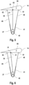
- the trim mechanism 39 in Fig. 4 The underlying principle is Fig. 5 once again using a simplified Schematic diagram explained. Shown is the Fig. 4 The longitudinal section shown on the left through the kite 14, which is connected to the first branching block 27.
- the front tension cord 48 can be shortened and the rear tension cord 49 can be lengthened.
- the middle articulation point 31 of the three articulation points 31, 61, 62 is connected to the first branching block 27 via a line 55 of fixed length, a pitching movement results, the local pitch axis 51 of which coincides with the middle articulation point 31.
- the articulation points 31, 61, 62 arranged in a common longitudinal plane of the kite 14 form a set 56 of articulation points.
- the kite 14 can be connected to the branching blocks 27, 28 or to the gondola 25 via a larger number of sets 56 of articulation points lying parallel to one another.
- the middle pivot point 31 is located near the pressure point 63 of the kite, so that no great force is required to change the angle of attack of the kite 14.
- the middle pivot point 31 is arranged centrally between the front pivot point 61 and the rear pivot point 62.
- the set 56 of articulation points 31 is designed in such a way that the pitching movement about the local pitch axis 51 simultaneously causes a change in the local geometric shape of the kite 14.
- the middle articulation point has a smaller distance to the rear articulation point than to the front articulation point.
- shortening the front pull cord 48 and lengthening the rear pull cord 49 leads to an increased curvature of the kite 14.
- An increased curvature may be desired, for example, so that the kite 14 maintains a stable flight condition despite low flight speed.
- the front articulation point 31 is connected to the first branching block 27 via a line 55 of fixed length.
- the two rear articulation points 61, 62 are coupled to the first branching block 27 via the trim pulley 41 in the manner of a pulley.
- the trim cable 41 is released in the state shown, the rear pivot point 62 moves upwards faster than the middle pivot point 61. This results in a pitching movement, the local pitch axis 51 of which lies in front of the two pivot points 61, 62 that have moved upwards.
- the local geometric shape of the kite 14 is maintained during the pitching movement.
- the trim cable 41 forms the tension cord for the two moving pivot points 31 between the kite 14 and the first branching block 27, the length of which can be changed.
- the kite system in Fig. 4 is designed so that the front actuating line 45 and the rear actuating line 46 have identical actuating paths. If this is not desired, a drive roller 42 having a stepped diameter can be used for the trim mechanism 40. In Fig. 9 an embodiment of such a stepped drive roller 42 is shown, over which a third actuating line 57 is guided in addition to the front actuating line 45 and the rear actuating line 46. Due to the three different diameters of the drive roller 42, the actuating paths of the three actuating lines differ from one another.
- kite system 23 according to the invention is used to generate a propulsion force for a ship 43.
Landscapes
- Engineering & Computer Science (AREA)
- Aviation & Aerospace Engineering (AREA)
- Life Sciences & Earth Sciences (AREA)
- Sustainable Development (AREA)
- Sustainable Energy (AREA)
- Chemical & Material Sciences (AREA)
- Combustion & Propulsion (AREA)
- Mechanical Engineering (AREA)
- General Engineering & Computer Science (AREA)
- Ocean & Marine Engineering (AREA)
- Toys (AREA)
- Wind Motors (AREA)
Priority Applications (5)
| Application Number | Priority Date | Filing Date | Title |
|---|---|---|---|
| EP23174818.7A EP4467451A1 (fr) | 2023-05-23 | 2023-05-23 | Système de kit et procédé de fonctionnement d'un système de kit |
| CN202480034432.6A CN121368557A (zh) | 2023-05-23 | 2024-05-07 | 风筝系统和用于操作风筝系统的方法 |
| EP24723891.8A EP4716654A1 (fr) | 2023-05-23 | 2024-05-07 | Système de cerf-volant et procédé pour faire fonctionner un système de cerf-volant |
| PCT/EP2024/062526 WO2024240486A1 (fr) | 2023-05-23 | 2024-05-07 | Système de cerf-volant et procédé pour faire fonctionner un système de cerf-volant |
| AU2024276287A AU2024276287A1 (en) | 2023-05-23 | 2024-05-07 | Kite system and method for operating a kite system |
Applications Claiming Priority (1)
| Application Number | Priority Date | Filing Date | Title |
|---|---|---|---|
| EP23174818.7A EP4467451A1 (fr) | 2023-05-23 | 2023-05-23 | Système de kit et procédé de fonctionnement d'un système de kit |
Publications (1)
| Publication Number | Publication Date |
|---|---|
| EP4467451A1 true EP4467451A1 (fr) | 2024-11-27 |
Family
ID=86609630
Family Applications (2)
| Application Number | Title | Priority Date | Filing Date |
|---|---|---|---|
| EP23174818.7A Withdrawn EP4467451A1 (fr) | 2023-05-23 | 2023-05-23 | Système de kit et procédé de fonctionnement d'un système de kit |
| EP24723891.8A Pending EP4716654A1 (fr) | 2023-05-23 | 2024-05-07 | Système de cerf-volant et procédé pour faire fonctionner un système de cerf-volant |
Family Applications After (1)
| Application Number | Title | Priority Date | Filing Date |
|---|---|---|---|
| EP24723891.8A Pending EP4716654A1 (fr) | 2023-05-23 | 2024-05-07 | Système de cerf-volant et procédé pour faire fonctionner un système de cerf-volant |
Country Status (4)
| Country | Link |
|---|---|
| EP (2) | EP4467451A1 (fr) |
| CN (1) | CN121368557A (fr) |
| AU (1) | AU2024276287A1 (fr) |
| WO (1) | WO2024240486A1 (fr) |
Citations (7)
| Publication number | Priority date | Publication date | Assignee | Title |
|---|---|---|---|---|
| US20010004097A1 (en) * | 1999-12-15 | 2001-06-21 | Hans-Jurgen Schwarzler | Actuation system and method for a load-bearing paraglider |
| WO2007112993A1 (fr) | 2006-03-31 | 2007-10-11 | Skysails Gmbh & Co. Kg | Installation à énergie éolienne à cerf-volant pouvant être commandé |
| US20100282153A1 (en) * | 2006-09-14 | 2010-11-11 | Skysails Gmbh & Co. Kg | Steering Unit for Free Flying, Confined Wing Element |
| WO2011076270A1 (fr) * | 2009-12-22 | 2011-06-30 | Philippe Dubois | Mécanismes de commande de stabilisation et d'orientation pour ailes ou voiles de traction comprenant une aile |
| US8607722B2 (en) * | 2007-12-19 | 2013-12-17 | Skysails Gmbh & Co. Kg | Aerodynamic wind propulsion device having active and passive steering lines and method for controlling of such a device |
| US9046072B2 (en) * | 2010-08-05 | 2015-06-02 | Crosswind Power Systems Inc. | Method and system for harnessing wind energy using a tethered airfoil |
| WO2021239975A1 (fr) * | 2020-05-29 | 2021-12-02 | Enevate B.V. | Cerf-volant de traction et système de bride |
-
2023
- 2023-05-23 EP EP23174818.7A patent/EP4467451A1/fr not_active Withdrawn
-
2024
- 2024-05-07 CN CN202480034432.6A patent/CN121368557A/zh active Pending
- 2024-05-07 AU AU2024276287A patent/AU2024276287A1/en active Pending
- 2024-05-07 WO PCT/EP2024/062526 patent/WO2024240486A1/fr not_active Ceased
- 2024-05-07 EP EP24723891.8A patent/EP4716654A1/fr active Pending
Patent Citations (7)
| Publication number | Priority date | Publication date | Assignee | Title |
|---|---|---|---|---|
| US20010004097A1 (en) * | 1999-12-15 | 2001-06-21 | Hans-Jurgen Schwarzler | Actuation system and method for a load-bearing paraglider |
| WO2007112993A1 (fr) | 2006-03-31 | 2007-10-11 | Skysails Gmbh & Co. Kg | Installation à énergie éolienne à cerf-volant pouvant être commandé |
| US20100282153A1 (en) * | 2006-09-14 | 2010-11-11 | Skysails Gmbh & Co. Kg | Steering Unit for Free Flying, Confined Wing Element |
| US8607722B2 (en) * | 2007-12-19 | 2013-12-17 | Skysails Gmbh & Co. Kg | Aerodynamic wind propulsion device having active and passive steering lines and method for controlling of such a device |
| WO2011076270A1 (fr) * | 2009-12-22 | 2011-06-30 | Philippe Dubois | Mécanismes de commande de stabilisation et d'orientation pour ailes ou voiles de traction comprenant une aile |
| US9046072B2 (en) * | 2010-08-05 | 2015-06-02 | Crosswind Power Systems Inc. | Method and system for harnessing wind energy using a tethered airfoil |
| WO2021239975A1 (fr) * | 2020-05-29 | 2021-12-02 | Enevate B.V. | Cerf-volant de traction et système de bride |
Also Published As
| Publication number | Publication date |
|---|---|
| EP4716654A1 (fr) | 2026-04-01 |
| AU2024276287A1 (en) | 2026-01-08 |
| CN121368557A (zh) | 2026-01-20 |
| WO2024240486A1 (fr) | 2024-11-28 |
Similar Documents
| Publication | Publication Date | Title |
|---|---|---|
| DE1475819C3 (de) | Verfahren zum Verlegen einer Rohrleitung auf dem Boden eines Gewässers | |
| DE19960332C1 (de) | Stellantriebssystem und Verfahren für einen Lastengleitschirm | |
| DE3046940C2 (fr) | ||
| WO2005102803A1 (fr) | Systeme de store pour toit de vehicule | |
| DE1771114A1 (de) | Glasschneidegeraet | |
| EP0070793A1 (fr) | Dispositif pour le câblage SZ avec une disque de toronnage et un accumulateur en forme de tube | |
| WO2014040716A1 (fr) | Éolienne volante multicâbles à fonctionnement en yoyo | |
| EP4514671A1 (fr) | Système de transport par cordes, en particulier pour un système de sport de loisirs | |
| DE3319950A1 (de) | Manuelle fernschaltvorrichtung | |
| EP4716654A1 (fr) | Système de cerf-volant et procédé pour faire fonctionner un système de cerf-volant | |
| DE1781191A1 (de) | Schublenk- bzw. -richteinrichtung | |
| DE10113561B4 (de) | Vorschubvorrichtung für eine Ramm- und/oder Bohrvorrichtung | |
| DE2855593C2 (de) | Vorrichtung zum reversierenden Verseilen schwer verformbarer Starkstromkabeladern | |
| DE2117093A1 (de) | Kabelverseilvorrichtung | |
| EP3453608B1 (fr) | Procédé et système d'arrimage d'un élément soumis à l'action du vent | |
| DE102021101419A1 (de) | Sonnenschutzanlage mit einem Zugsystem | |
| DE2658164A1 (de) | Vorrichtung zum ausziehen von mehrfachbuendelleitern | |
| DE1953479A1 (de) | Verfahren und Anlage zur kontinuierlichen Herstellung vieladriger Kabel | |
| EP1388637B1 (fr) | Rouleau | |
| DE102022121973B4 (de) | Seilfördersystem, insbesondere für eine Funsportanlage | |
| WO2025180768A1 (fr) | Procédé de démarrage d'un système de cerf-volant, unité de commande pour un dispositif de cerf-volant, et dispositif de cerf-volant | |
| DE2751989A1 (de) | Vorrichtung zum aufwickeln von biegbarem, langgestrecktem gut | |
| DE2031729C3 (de) | Verfahren zum Verlegen von Schaltdrähten in Verdrahtungsfeldern | |
| DE10323382A1 (de) | Verfahren zum Erzeugen einer Musterkette und Musterkettenschärmaschine | |
| EP4234401A1 (fr) | Procédé d'atterrissage d'un système de cerf-volant et système de cerf-volant |
Legal Events
| Date | Code | Title | Description |
|---|---|---|---|
| PUAI | Public reference made under article 153(3) epc to a published international application that has entered the european phase |
Free format text: ORIGINAL CODE: 0009012 |
|
| STAA | Information on the status of an ep patent application or granted ep patent |
Free format text: STATUS: THE APPLICATION HAS BEEN PUBLISHED |
|
| AK | Designated contracting states |
Kind code of ref document: A1 Designated state(s): AL AT BE BG CH CY CZ DE DK EE ES FI FR GB GR HR HU IE IS IT LI LT LU LV MC ME MK MT NL NO PL PT RO RS SE SI SK SM TR |
|
| STAA | Information on the status of an ep patent application or granted ep patent |
Free format text: STATUS: THE APPLICATION IS DEEMED TO BE WITHDRAWN |
|
| 18D | Application deemed to be withdrawn |
Effective date: 20250528 |