EP4234764B1 - Procédé de fabrication d'un séparateur asymétrique - Google Patents
Procédé de fabrication d'un séparateur asymétrique Download PDFInfo
- Publication number
- EP4234764B1 EP4234764B1 EP23168166.9A EP23168166A EP4234764B1 EP 4234764 B1 EP4234764 B1 EP 4234764B1 EP 23168166 A EP23168166 A EP 23168166A EP 4234764 B1 EP4234764 B1 EP 4234764B1
- Authority
- EP
- European Patent Office
- Prior art keywords
- manufacturing
- max
- separator
- porous
- vips
- Prior art date
- Legal status (The legal status is an assumption and is not a legal conclusion. Google has not performed a legal analysis and makes no representation as to the accuracy of the status listed.)
- Active
Links
Images

Classifications
-
- C—CHEMISTRY; METALLURGY
- C25—ELECTROLYTIC OR ELECTROPHORETIC PROCESSES; APPARATUS THEREFOR
- C25B—ELECTROLYTIC OR ELECTROPHORETIC PROCESSES FOR THE PRODUCTION OF COMPOUNDS OR NON-METALS; APPARATUS THEREFOR
- C25B13/00—Diaphragms; Spacing elements
- C25B13/02—Diaphragms; Spacing elements characterised by shape or form
-
- B—PERFORMING OPERATIONS; TRANSPORTING
- B01—PHYSICAL OR CHEMICAL PROCESSES OR APPARATUS IN GENERAL
- B01D—SEPARATION
- B01D67/00—Processes specially adapted for manufacturing semi-permeable membranes for separation processes or apparatus
- B01D67/0002—Organic membrane manufacture
- B01D67/0009—Organic membrane manufacture by phase separation, sol-gel transition, evaporation or solvent quenching
-
- B—PERFORMING OPERATIONS; TRANSPORTING
- B01—PHYSICAL OR CHEMICAL PROCESSES OR APPARATUS IN GENERAL
- B01D—SEPARATION
- B01D67/00—Processes specially adapted for manufacturing semi-permeable membranes for separation processes or apparatus
- B01D67/0002—Organic membrane manufacture
- B01D67/0009—Organic membrane manufacture by phase separation, sol-gel transition, evaporation or solvent quenching
- B01D67/00091—Organic membrane manufacture by phase separation, sol-gel transition, evaporation or solvent quenching by evaporation
-
- B—PERFORMING OPERATIONS; TRANSPORTING
- B01—PHYSICAL OR CHEMICAL PROCESSES OR APPARATUS IN GENERAL
- B01D—SEPARATION
- B01D67/00—Processes specially adapted for manufacturing semi-permeable membranes for separation processes or apparatus
- B01D67/0002—Organic membrane manufacture
- B01D67/0009—Organic membrane manufacture by phase separation, sol-gel transition, evaporation or solvent quenching
- B01D67/0016—Coagulation
-
- B—PERFORMING OPERATIONS; TRANSPORTING
- B01—PHYSICAL OR CHEMICAL PROCESSES OR APPARATUS IN GENERAL
- B01D—SEPARATION
- B01D67/00—Processes specially adapted for manufacturing semi-permeable membranes for separation processes or apparatus
- B01D67/0079—Manufacture of membranes comprising organic and inorganic components
- B01D67/00793—Dispersing a component, e.g. as particles or powder, in another component
-
- B—PERFORMING OPERATIONS; TRANSPORTING
- B01—PHYSICAL OR CHEMICAL PROCESSES OR APPARATUS IN GENERAL
- B01D—SEPARATION
- B01D69/00—Semi-permeable membranes for separation processes or apparatus characterised by their form, structure or properties; Manufacturing processes specially adapted therefor
- B01D69/10—Supported membranes; Membrane supports
- B01D69/107—Organic support material
- B01D69/1071—Woven, non-woven or net mesh
-
- B—PERFORMING OPERATIONS; TRANSPORTING
- B01—PHYSICAL OR CHEMICAL PROCESSES OR APPARATUS IN GENERAL
- B01D—SEPARATION
- B01D69/00—Semi-permeable membranes for separation processes or apparatus characterised by their form, structure or properties; Manufacturing processes specially adapted therefor
- B01D69/10—Supported membranes; Membrane supports
- B01D69/108—Inorganic support material
-
- B—PERFORMING OPERATIONS; TRANSPORTING
- B01—PHYSICAL OR CHEMICAL PROCESSES OR APPARATUS IN GENERAL
- B01D—SEPARATION
- B01D69/00—Semi-permeable membranes for separation processes or apparatus characterised by their form, structure or properties; Manufacturing processes specially adapted therefor
- B01D69/14—Dynamic membranes
- B01D69/141—Heterogeneous membranes, e.g. containing dispersed material; Mixed matrix membranes
- B01D69/148—Organic/inorganic mixed matrix membranes
-
- C—CHEMISTRY; METALLURGY
- C25—ELECTROLYTIC OR ELECTROPHORETIC PROCESSES; APPARATUS THEREFOR
- C25B—ELECTROLYTIC OR ELECTROPHORETIC PROCESSES FOR THE PRODUCTION OF COMPOUNDS OR NON-METALS; APPARATUS THEREFOR
- C25B1/00—Electrolytic production of inorganic compounds or non-metals
- C25B1/01—Products
- C25B1/02—Hydrogen or oxygen
- C25B1/04—Hydrogen or oxygen by electrolysis of water
-
- C—CHEMISTRY; METALLURGY
- C25—ELECTROLYTIC OR ELECTROPHORETIC PROCESSES; APPARATUS THEREFOR
- C25B—ELECTROLYTIC OR ELECTROPHORETIC PROCESSES FOR THE PRODUCTION OF COMPOUNDS OR NON-METALS; APPARATUS THEREFOR
- C25B1/00—Electrolytic production of inorganic compounds or non-metals
- C25B1/01—Products
- C25B1/02—Hydrogen or oxygen
- C25B1/04—Hydrogen or oxygen by electrolysis of water
- C25B1/044—Hydrogen or oxygen by electrolysis of water producing mixed hydrogen and oxygen gas, e.g. Brown's gas [HHO]
-
- C—CHEMISTRY; METALLURGY
- C25—ELECTROLYTIC OR ELECTROPHORETIC PROCESSES; APPARATUS THEREFOR
- C25B—ELECTROLYTIC OR ELECTROPHORETIC PROCESSES FOR THE PRODUCTION OF COMPOUNDS OR NON-METALS; APPARATUS THEREFOR
- C25B11/00—Electrodes; Manufacture thereof not otherwise provided for
- C25B11/02—Electrodes; Manufacture thereof not otherwise provided for characterised by shape or form
- C25B11/03—Electrodes; Manufacture thereof not otherwise provided for characterised by shape or form perforated or foraminous
- C25B11/031—Porous electrodes
- C25B11/032—Gas diffusion electrodes
-
- C—CHEMISTRY; METALLURGY
- C25—ELECTROLYTIC OR ELECTROPHORETIC PROCESSES; APPARATUS THEREFOR
- C25B—ELECTROLYTIC OR ELECTROPHORETIC PROCESSES FOR THE PRODUCTION OF COMPOUNDS OR NON-METALS; APPARATUS THEREFOR
- C25B13/00—Diaphragms; Spacing elements
- C25B13/04—Diaphragms; Spacing elements characterised by the material
- C25B13/08—Diaphragms; Spacing elements characterised by the material based on organic materials
-
- C—CHEMISTRY; METALLURGY
- C25—ELECTROLYTIC OR ELECTROPHORETIC PROCESSES; APPARATUS THEREFOR
- C25B—ELECTROLYTIC OR ELECTROPHORETIC PROCESSES FOR THE PRODUCTION OF COMPOUNDS OR NON-METALS; APPARATUS THEREFOR
- C25B9/00—Cells or assemblies of cells; Constructional parts of cells; Assemblies of constructional parts, e.g. electrode-diaphragm assemblies; Process-related cell features
- C25B9/01—Electrolytic cells characterised by shape or form
-
- C—CHEMISTRY; METALLURGY
- C25—ELECTROLYTIC OR ELECTROPHORETIC PROCESSES; APPARATUS THEREFOR
- C25B—ELECTROLYTIC OR ELECTROPHORETIC PROCESSES FOR THE PRODUCTION OF COMPOUNDS OR NON-METALS; APPARATUS THEREFOR
- C25B9/00—Cells or assemblies of cells; Constructional parts of cells; Assemblies of constructional parts, e.g. electrode-diaphragm assemblies; Process-related cell features
- C25B9/17—Cells comprising dimensionally-stable non-movable electrodes; Assemblies of constructional parts thereof
- C25B9/19—Cells comprising dimensionally-stable non-movable electrodes; Assemblies of constructional parts thereof with diaphragms
- C25B9/21—Cells comprising dimensionally-stable non-movable electrodes; Assemblies of constructional parts thereof with diaphragms two or more diaphragms
-
- C—CHEMISTRY; METALLURGY
- C25—ELECTROLYTIC OR ELECTROPHORETIC PROCESSES; APPARATUS THEREFOR
- C25B—ELECTROLYTIC OR ELECTROPHORETIC PROCESSES FOR THE PRODUCTION OF COMPOUNDS OR NON-METALS; APPARATUS THEREFOR
- C25B9/00—Cells or assemblies of cells; Constructional parts of cells; Assemblies of constructional parts, e.g. electrode-diaphragm assemblies; Process-related cell features
- C25B9/70—Assemblies comprising two or more cells
- C25B9/73—Assemblies comprising two or more cells of the filter-press type
-
- C—CHEMISTRY; METALLURGY
- C25—ELECTROLYTIC OR ELECTROPHORETIC PROCESSES; APPARATUS THEREFOR
- C25B—ELECTROLYTIC OR ELECTROPHORETIC PROCESSES FOR THE PRODUCTION OF COMPOUNDS OR NON-METALS; APPARATUS THEREFOR
- C25B9/00—Cells or assemblies of cells; Constructional parts of cells; Assemblies of constructional parts, e.g. electrode-diaphragm assemblies; Process-related cell features
- C25B9/70—Assemblies comprising two or more cells
- C25B9/73—Assemblies comprising two or more cells of the filter-press type
- C25B9/77—Assemblies comprising two or more cells of the filter-press type having diaphragms
-
- B—PERFORMING OPERATIONS; TRANSPORTING
- B01—PHYSICAL OR CHEMICAL PROCESSES OR APPARATUS IN GENERAL
- B01D—SEPARATION
- B01D61/00—Processes of separation using semi-permeable membranes, e.g. dialysis, osmosis or ultrafiltration; Apparatus, accessories or auxiliary operations specially adapted therefor
- B01D61/42—Electrodialysis; Electro-osmosis ; Electro-ultrafiltration; Membrane capacitive deionization
-
- Y—GENERAL TAGGING OF NEW TECHNOLOGICAL DEVELOPMENTS; GENERAL TAGGING OF CROSS-SECTIONAL TECHNOLOGIES SPANNING OVER SEVERAL SECTIONS OF THE IPC; TECHNICAL SUBJECTS COVERED BY FORMER USPC CROSS-REFERENCE ART COLLECTIONS [XRACs] AND DIGESTS
- Y02—TECHNOLOGIES OR APPLICATIONS FOR MITIGATION OR ADAPTATION AGAINST CLIMATE CHANGE
- Y02E—REDUCTION OF GREENHOUSE GAS [GHG] EMISSIONS, RELATED TO ENERGY GENERATION, TRANSMISSION OR DISTRIBUTION
- Y02E60/00—Enabling technologies; Technologies with a potential or indirect contribution to GHG emissions mitigation
- Y02E60/30—Hydrogen technology
- Y02E60/36—Hydrogen production from non-carbon containing sources, e.g. by water electrolysis
Definitions
- the present invention relates to a method of manufacturing an asymmetric separator for alkaline water electrolysis.
- Hydrogen is being considered an important future energy carrier, which means it can store and deliver energy in a usable form. Energy is released by an exothermic combustion reaction with oxygen thereby forming water. During such combustion reaction, no greenhouse gases containing carbon are emitted.
- hydrogen is not an energy source itself; it can only be produced from other sources of energy, such as fossil fuels, renewable sources or nuclear power by different energy conversion processes.
- Alkaline water electrolysis is an important manufacturing process of hydrogen.
- a so-called separator or diaphragm is used to separate the electrodes of different polarity to prevent a short circuit between these electronic conducting parts (electrodes) and to prevent the recombination of H 2 (formed at the cathode) and O 2 (formed at the anode) by avoiding gas crossover. While serving in all these functions, the separator should also be a highly ionic conductor for transportation of OH- ions from the cathode to the anode.
- EP232923 discloses an ion-permeable diaphragm prepared by immersing an organic fabric in a dope solution, which is applied on a glass sheet. After phase inversion, the diaphragm is then removed from the glass sheet. There is however a large difference between the maximum pore diameters of both sides of a separator prepared according to the method disclosed in EP-A 232923 .
- EP-A 1776490 discloses a process of preparing an ion-permeable web-reinforced separator membrane.
- the process leads to a membrane with symmetrical characteristics.
- the process includes the steps of providing a web and a suitable paste, guiding the web in a vertical position, equally coating both sides of the web with the paste to produce a paste coated web, and applying a symmetrical surface pore formation step and a symmetrical coagulation step to the paste coated web to produce a web-reinforced membrane.
- WO2009/147084 discloses manufacturing technology to produce a membrane with symmetrical characteristics as described in EP-A 1776490 .
- WO 2016/203701 A1 discloses a diaphragm for water elecrolysis.
- the separator disclosed in the above mentioned patent applications has identical pore sizes on both sides of the separator, herein referred to as a symmetric separator.
- the separator preferably has "small" pore sizes.
- a disadvantage of a symmetric separator having such "small” pore sizes is the occurrence of the so-called "bubble trap". Gas solubilized in the electrolyte may separate from the electrolyte due to a higher temperature inside the separator. Such gas cannot leave the separator due to the small pores on each side of the separator, resulting in a loss of efficiency.
- Another object of the invention is to provide a manufacturing method to produce such a separator.
- the present invention relates to the method of manufacturing an asymmetric separator for alkaline water electrolysis in accordance with claim 1. Specific embodiments are the subject-matter of the dependent claims.
- the reinforced separator for alkaline hydrolysis (1) manufactured according to the present invention comprises a porous support (10), a first porous polymer layer (20) contiguous with one side of the support and a second porous polymer layer (30) contiguous with the other side of the support, characterized in that the maximum pore diameter at the outer surface of the first porous polymer layer (PD max (1)) and of the second porous polymer layer (PD max (2)) are different from each other and wherein a ratio PDmax(2)/PDmax(1) is between 1.25 and 10.
- the ratio PDmax(2)/PDmax(1) is preferably between 2 and 7.5, more preferably between 2.5 and 5.
- PD max (1) is preferably between 0.05 ⁇ m and 0.3 ⁇ m, more preferably between 0.08 ⁇ m and 0.25 ⁇ m, most preferably between 0.1 ⁇ m and 0.2 ⁇ m.
- PD max (2) is preferably between 0.2 ⁇ m and 6.5 ⁇ m, more preferably between 0.2 ⁇ m and 1.50 ⁇ m, most preferably between 0.2 ⁇ m and 0.5 ⁇ m.
- the smaller PDmax(1) ensure an efficient separation of H 2 and O 2 while PDmax(2) ensures a good penetration of the electrolyte in the separator resulting in a sufficient ionic conductivity.
- the porosity of the separator is preferably between 30 and 70 %, more preferably between 40 and 60 %.
- the thickness of the separator is preferably between 100 and 1000 ⁇ m, more preferably between 250 and 750 ⁇ m. If the thickness of the separator is less than 100 ⁇ m, its physical strength maybe insufficient, when the thickness is above 1000 ⁇ m, the electrolysis efficiency may decrease.
- the maximum pore diameter referred to is measured using the Bubble Point Test method as below. That method is described in American Society for Testing and Materials Standard (ASMT) Method F316.
- the porous support is used to reinforce the separator to ensure its mechanical strength.
- the porous support includes a porous fabric, porous metal plates or porous ceramic plates.
- the porous support is preferably a porous fabric, more preferably a porous polymer fabric.
- Suitable porous polymer fabrics are prepared from polypropylene (PP), polyethylene (PE), polysulfone (PS), polyphenylene sulfide (PPS), polyamide/nylon (PA), polyethersulfone (PES), polyphenyl sulfone, polyethylene terephthalate (PET), polyether-ether ketone (PEEK), sulfonated polyether-ether keton (s-PEEK), monochlorotrifluoroethylene (CTFE), copolymers of ethylene with tetrafluorethylene (TFE) or chlorotrifluorethylene (CTFE), polyimide, polyether imide and m-aramide.
- PP polypropylene
- PE polyethylene
- PS polysulfone
- PPS polyphenylene sulfide
- PA polyamide/nylon
- PES polyethersulfone
- PET polyethylene terephthalate
- PEEK polyether-ether ketone
- s-PEEK
- the temperature limit of the separator (for long-term stability in strong alkaline conditions) may depend on the porous support used.
- a preferred porous support for low temperature applications ( ⁇ 80°C) is made of polyproplylene, while a preferred porous support for high temperature applications ( ⁇ 120°C) is prepared from an ethylene-tetrafluoroethylene copolymer or from polyether-ether ketone.
- the porous polymer fabric may be woven or non-woven.
- the open area of the porous support is preferably between 20 and 80%, more preferably between 40 and 70 %, to ensure good penetration of the electrolyte into the support.
- the porous support has pores or mesh openings preferably having an average diameter between 100 and 1000 ⁇ m, more preferably between 300 and 700 ⁇ m.
- the support preferably has a thickness between 100 and 750 ⁇ m, more preferably between 125 and 300 ⁇ m.
- the porous support is preferably a continuous web to enable a manufacturing process as disclosed in EP-A 1776490 and WO2009/147084 and disclosed below.
- the first and the second porous polymer layer comprises a polymer, also referred to as membrane polymer.
- the polymer forms a three dimensional porous network, the result of a phase inversion step in the preparation of the separator, as described below.
- the membrane polymer is selected from the group consisting of polysulfone (PSU), polyether sulfone (PES), polyvinylidene fluoride (PVDF), polyacrylonitrile (PAN), polyethyleneoxide (PEO), polymethylmethacrylate (PMMA) and copolymers thereof.
- PSU polysulfone
- PES polyether sulfone
- PVDF polyvinylidene fluoride
- PAN polyacrylonitrile
- PEO polyethyleneoxide
- PMMA polymethylmethacrylate
- PVDF and vinylidenefluoride (VDF)-copolymers are preferred for their oxidation/reduction resistance and film-forming properties.
- terpolymers of VDF, hexanefluoropropylene (HFP) and chlorotrifluoroethylene (CTFE) are preferred for their excellent swelling properties, heat resistance and adhesion to electrodes.
- a particularly preferred membrane polymer is polysulfone, as disclosed in for example EP-A 3085815 , paragraph [0027] to [0032].
- Another preferred membrane polymer is a polyether sulfone (PES), disclosed in EP-A 3085815 , paragraphs [0021] to [0026].
- PES polyether sulfone
- the polyether sulfone may be mixed with polysulfone as also disclosed in EP-A 3085815 .
- the porous polymer layer preferably also comprises a hydrophilic inorganic material.
- the hydrophilic inorganic material may further improve the ionic conductivity trough the separator.
- the hydrophilic inorganic material is selected from the group consisting of Ti0 2 , HfO 2 , Al 2 O 3 , ZrO2, Zr 3 (PO 4 ) 4 , Y 2 O 3 , SiO 2 , perovskite oxide materials, SiC, BaSO 4 , and C(Pt/Rh/Ru).
- More preferred hydrophilic inorganic materials are metal oxides and hydroxides.
- Highly preferred hydrophilic inorganic materials are TiO 2 , BaSO 4 and ZrO 2 .
- the reinforced separator for alkaline hydrolysis as described above is prepared by a manufacturing method comprising the steps of:
- a preferred method of manufacturing the reinforced separator is disclosed in EP-A 1776490 (VITO ) and WO2009/147084 (Agfa Gevaert) . These methods result in web-reinforced separators wherein the web, i.e. the porous support, is nicely embedded in the separator, without appearance of the web at a surface of the separator.
- the same manufacturing method is used, however using different dope solution for each side of the separator and/or using different phase separation steps, in particular different VIPS steps, for each side of the separator.
- different dope solution for each side of the separator and/or using different phase separation steps, in particular different VIPS steps, for each side of the separator.
- an asymmetric separator as described above may be obtained.
- the dope solution comprises a membrane polymer as described above, a hydrophilic inorganic material as described above and a solvent.
- the solvent of the dope solution is preferably an organic solvent wherein the membrane polymer can be dissolved. Moreover, the organic solvent is preferably miscible in water.
- the solvent is preferably selected from N-methyl-2-pyrrolidone (NMP), N-ethyl-pyrrolidone (NEP), N,N-dimethylformamide (DMF), formamide, dimethylsulfoxide (DMSO), N,N-dimethylacetamide (DMAC), acetonitrile, and mixtures thereof.
- the dope solution may further comprise other ingredients to optimize the properties of the obtained polymer layers, for example their porosity and the maximum pore diameter at their outer surface.
- the dope solution preferably comprises a pore forming promoting agent such as polyvinylpyrrolidone (PVP), polyvinylalcohol (PVA), polyvinylacetate (PVAc), methylcellulose and polyethylene oxide. These compounds may have an influence on the maximum pore diameter and/or the porosity of the porous polymer layers.
- a pore forming promoting agent such as polyvinylpyrrolidone (PVP), polyvinylalcohol (PVA), polyvinylacetate (PVAc), methylcellulose and polyethylene oxide.
- the concentration of these pore forming promoting agents in the dope solution is preferably between 0.1 and 15 wt%, more preferably between 0.5 and 10 wt%.
- the dope solution comprises glycerol.
- Glycerol also has an influence on the pore formation in the porous polymer layer.
- the concentration of glycerol is preferably between 0.1 and 15 wt%, more preferably between 0.5 and 5 wt%.
- the dope solution used to prepare the first porous polymeric layer may be identical to the dope solution used to prepare the second porous polymeric layer, or the dope solution used for both polymeric layers may be different from each other.
- the dope solution used to prepare the first porous polymeric layer may be optimized to obtain small maximum pore diameters (PD max (1)), while the dope solution to prepare the second porous polymeric layer may be optimized to obtain larger maximum pore diameters (PD max (2)), for example by optimizing the concentration of glycerol and/or PVP in de dope solutions.
- the dope solution may be applied to the surface of the support by any coating or casting technique.
- a preferred coating technique is for example extrusion coating.
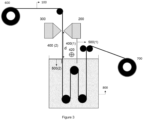
- the dope solutions are applied by a slot die coating technique wherein two slot coating dies ( Figures 2 and 3 , 200 and 300) are located on either side of the porous support.
- the slot coating dies are capable of holding the dope solution at a predetermined temperature, distributing the dope solutions uniformly over the support, and adjusting the coating thickness of the applied dope solutions.
- the viscosity of the dope solutions when used in a slot die coating technique, is preferably between 1 and 500 Pa.s, more preferably between 10 and 100 Pa.s, at coating temperature and at a shear rate of 1 s -1 .
- the dope solutions are preferably shear-thinning.
- the ratio of the viscosity at a shear rate of 1 s -1 to the viscosity at a shear rate of 100 s -1 is preferably at least 2, more preferably at least 2.5, most preferably at least 5.
- the porous support is preferably a continuous web, which is transported downwards between the slot coating dies (200, 300) as shown in Figures 2 and 3 .
- the coating thickness is adjusted to obtain a first and a second polymer layer having a desired thickness.
- the porous support becomes impregnated with the dope solutions.
- the phase inversion step comprises a so-called Liquid Induced Phase Separation (LIPS) step and preferably a combination a Vapour Induced Phase Separation (VIPS) step and a LIPS step.
- LIPS Liquid Induced Phase Separation
- VIPS Vapour Induced Phase Separation
- the porous support coated on both sides with the dope solution is contacted with a non-solvent that is miscible with the solvent of the dope solution.
- this is carried out by immersing the porous support coated on both sides with the dope solutions into a non-solvent bath, also referred to as coagulation bath.
- a non-solvent bath also referred to as coagulation bath.
- the non-solvent is preferably water, mixtures of water and an aprotic solvent selected from the group consisting of N-methylpyrrolidone (NMP), dimethylformamide (DMF), dimethylsulfoxide (DMSO) and dimethylacetamide (DMAC), water solutions of water-soluble polymers such as PVP or PVA, or mixtures of water and alcohols, such as ethanol, propanol or isopropanol.
- NMP N-methylpyrrolidone
- DMF dimethylformamide
- DMSO dimethylsulfoxide
- DMAC dimethylacetamide
- the non-solvent is most preferably water.
- the temperature of the water bath is preferably between 20 and 90°C, more preferably between 40 and 70°C.
- the continuous web (100) coated on either side with a dope solution is transported downwards, in a vertical position, towards the coagulation bath (800) as shown in Figures 2 and 3 .
- the porous support coated with the dope solutions is first exposed to humid air prior to immersion in the coagulation bath.
- water is a non-solvent such that the water transfer associated with the humid air exposure step leads to phase separation.
- VIPS is carried out in the area 400, between the slot coating dies (200, 300) and the surface of the non-solvent in the coagulation bath (800), which is shielded from the environment with for example thermal isolated metal plates (500).
- the extent and rate of water transfer in the VIPS step can be controlled by adjusting the velocity of the air, the relative humidity and temperature of the air, as well as the exposure time.
- the exposure time may be adjusted by changing the distance d between the slot coating dies (200, 300) and the surface of the non-solvent in the coagulation bath (800) and/or the speed with which the elongated web 100 is transported from the slot coating dies towards the coagulation bath.
- the relative humidity in the VIPS area (400) may be adjusted by the temperature of the coagulation bath and the shielding of the VIPS area (400) from the environment and from the coagulation bath.
- the speed of the air may be adjusted by the rotating speed of the ventilators (420) in the VIPS area (400).
- the VIPS step carried out on one side of the separator, resulting in the first porous polymer layer, and on the other side of the separator, resulting in the second porous polymer layer, may be identical or different from each other.
- the maximum pore diameter at the outer surface of the first porous polymer layer (PDmax(1)) and of the second porous polymer layer (PDmax(2)) may be adjusted to become different from each other and have the values as described above.
- a washing step may be carried out.
- a drying step is preferably carried out.
- Figures 2 and 3 schematically illustrates a preferred embodiment to manufacture a separator according to the present invention.
- the porous support is preferably a continuous web (100).
- the web is unwinded from a feed roller (600) and guided downwards in a vertical position between two coating units (200) and (300).
- a dope solution is coated on either side of the web.
- the coating thickness on either side of the web may be adjusted by optimizing the viscosity of the dope solutions and the distance between the coating units and the surface of the web.
- Preferred coating units are described in EP-B 2296825 , paragraphs [0043], [0047], [0048], [0060], [0063], and Figure 1 .
- the web coated on both sides with a dope solution is then transported over a distance d downwards towards a coagulation bath (800).
- the LIPS step is carried out.
- the VIPS step is carried out before entering the coagulation bath in the VIPS areas.
- the VIPS area (400) is identical on both sides of the coated web, while in Figure 3 , the VIPS areas (400(1)) and (400(2)) on either side of the coated web are different.
- the relative humidity (RH) and the air temperature in de VIPS area may be optimized using thermally isolated metal plates.
- the VIPS area (400) is completely shielded from the environment with such metal plates (500).
- the RH and temperature of the air is then mainly determined by the temperature of the coagulation bath.
- the air speed in the VIPS area may be adjusted by a ventilator (420).
- the VIPS areas (400(1)) and (400(2)) are different from each other.
- the VIPS area (400(1)) on one side of the coated web is identical to the VIPS area (400) in Figure 2 .
- the VIPS area (400(2)) on the other side of the coated web is different from the area (400(1)).
- the VIPS area (400(2)) is now shielded from the coagulation bath by a thermally isolated metal plate (500(2)).
- a high RH and/or a high air speed in a VIPS area typically result in a larger maximum pore diameter.
- the RH in one VIPS area is preferably above 85%, more preferably above 90%, most preferably above 95% while the RH in another VIPS area is preferably below 80%, more preferably below 75%, most preferably below 70%.
- the dried reinforced separator is then transported to a rolled up system (700).
- a liner may be provided on one side of the separator before rolling up the separator and the applied liner.
- Zr0 2 type E101 (a zirconium dioxide with an average particle size of 0.658 ⁇ m, a specific surface area of 22.26 m 2 /g, and a pore volume of 0.140 ml/g), commercially available from MEL-Chemicals.
- Udel P1700 NT LCD a polysulfone membrane polymer commercially available from SOLVAY.
- Glycerol a pore widening agent, commercially available from MOSSELMAN.
- NEP N-ethyl-pyrrolidone
- the pore diameters of the separators were measured using the so-called Bubble Point Test method.
- the bubble point test method is the most widely used for pore size determination. It is based on the fact that, for a given fluid and pore size with a constant wetting, the pressure required to force an air bubble through the pore is inverse proportion to the size of the hole.
- capillarity states that the height of a water column in a capillary is indirectly proportional to the capillary diameter.
- the pore size of the filter element can be established by wetting the element with the fluid and measuring the pressure at which the first stream of bubbles is emitted from the upper surface of the element.
- the top of the filter is placed in contact with the liquid, the bottom with air, the filter holder is connected to a source of a regulated pressure.
- the air pressure is gradually increased and the formation of bubbles on the liquid side is noted.
- gas passes across the filter only by diffusion, but when the pressure is high enough to dislodge liquid from the pores, bulk flow begins and bubbles will be seen.
- the initial bubble test pressure determines the size (and location) of the largest hole
- the open bubble point pressure determines the mean pore size of the element.
- the Bubble point, the average pore diameter, the maximum pore diameter and the gas permeability of the separators were measured using a POROLUX 1000, commercially available from POROTEC.
- a dope solution was prepared by mixing the ingredients of Table 1.
- Table 1 Ingredients wt% ZrO 2 40.65 Udel P1700 NT LCD 12.835 Glycerol 1 NEP 45.515
- the separator was prepared as disclosed in WO2009/147084 , examples 2 to 5 and Figure 2 of the present application.
- the dope solution was coated on both sides of a 1.7 m wide PPS-fabric using slot die coating technology at a speed of 1 m/min.
- the coated support was then transported towards a water bath (coagulation bath, 800) kept at 65°C.
- the coated support then entered the water bath for 5 minutes during which a liquid induced phase separation (HIPS) occurred.
- HIPS liquid induced phase separation
- the obtained separator was rolled up without drying, and afterwards cut in the desired format.
- the obtained symmetric separator S-SEP had a total thickness of 500 ⁇ m.
- the asymmetric separator As-SEP was prepared as described above, however using a different VIPS step, as shown in Figure 3 of the present application.
- the VIPS area 400(2) was open to the environment and the surface of the water bath was covered with a thermal isolating metal plate (500(2)). This resulted in VIPS area 400(2) having a RH of 70% and an air temperature of 25°C.
- the VIPS area 400(1) was enclosed from the environment with a shielding plate 500(1) and the surface of the water batch was not covered.
- the ventilation (420) in the area was 1m/s resulting in a RH of 98% and an air temperature of 65°C.
Landscapes
- Chemical & Material Sciences (AREA)
- Chemical Kinetics & Catalysis (AREA)
- Engineering & Computer Science (AREA)
- Organic Chemistry (AREA)
- Electrochemistry (AREA)
- Materials Engineering (AREA)
- Metallurgy (AREA)
- Inorganic Chemistry (AREA)
- Manufacturing & Machinery (AREA)
- Dispersion Chemistry (AREA)
- Separation Using Semi-Permeable Membranes (AREA)
- Laminated Bodies (AREA)
- Cell Separators (AREA)
- Electrolytic Production Of Non-Metals, Compounds, Apparatuses Therefor (AREA)
Claims (10)
- Procédé de fabrication d'un séparateur asymétrique pour l'électrolyse alcaline de l'eau comprenant les étapes consistant à:- appliquer une solution à filer contenant un polymère de membrane choisi parmi le groupe composé de polysulfone (PSU), de polyéthersulfone (PES), de fluorure de polyvinylidène (PVDF), de polyacrylonitrile (PAN), d'oxyde de polyéthylène (PEO), de polyméthacrylate de méthyle (PMMA) et de copolymères de ceux-ci, un matériau inorganique hydrophile choisi parmi le groupe composé de Ti02, HfO2, Al2O3, ZrO2, Zr3(PO4)4, Y2O3, SiO2, matériaux d'oxyde de pérovskite, SiC, BaSO4 et C(Pt/Rh/Ru), et un solvant sur les deux surfaces d'un support poreux,- effectuer une inversion de phase sur les solutions à filer appliquées, obtenant ainsi une première couche polymère poreuse contiguë à une face du support et une deuxième couche polymère poreuse contiguë à l'autre face du support,caractérisé en ce que le diamètre de pore maximal à la superficie extérieure de la première couche polymère poreuse (PDmax(1)) et de la deuxième couche polymère poreuse (PDmax(2)) sont différents et caractérisé en ce que le diamètre de pore maximal est mesuré selon le procédé de test du point de bulle ASTM F316,et caractérisé en ce qu'un rapport PDmax(2)/PDmax(1) est compris entre 1,25 et 10,caractérisé en ce qu'il est utilisé une solution à filer différente pour chaque face du séparateur et/ou qu'il est appliqué des étapes d'inversion de phase différentes pour chaque face du séparateur.
- Procédé de fabrication selon la revendication 1, caractérisé en ce que les étapes d'inversion de phase différentes sont des étapes de séparation de phase induite par vapeur différentes (étapes VIPS).
- Procédé de fabrication selon la revendication 1 ou 2, caractérisé en ce que le polymère de membrane est le polysulfone ou le polyéthersulfone (PES).
- Procédé de fabrication selon l'une quelconque des revendications 1 à 3, caractérisé en ce que le solvant est choisi parmi la N-méthyl-2-pyrrolidone (NMP), la N-éthylpyrrolidone (NEP), le N,N-diméthylformamide (DMF), le formamide, le diméthylsulfoxyde (DMSO), le N,N-diméthylacétamide (DMAC), l'acétonitrile et des mélanges de ceux-ci.
- Procédé de fabrication selon l'une quelconque des revendications 1 à 4, caractérisé en ce que le support poreux est un tissu polymère.
- Procédé de fabrication selon la revendication 5, caractérisé en ce que le tissu polymère est fabriqué à partir d'un polymère choisi parmi le groupe composé de polypropylène (PP), de polyéthylène (PE), de polysulfone (PS), de sulfure de polyphénylène (PPS), de polyamide/nylon (PA), de polyéthersulfone (PES), de sulfone de polyphényle, de polytéréphtalate d'éthylène (PET), de polyétheréthercétone (PEEK), de polyétheréthercétone sulfonée (s-PEEK), de monochlorotrifluoroéthylène (CTFE), de copolymères d'éthylène avec du tétrafluoroéthylène (TFE) ou du chlorotrifluoréthylène (CTFE), de polyimide, d'imide de polyéther et de m-aramide.
- Procédé de fabrication selon l'une quelconque des revendications 1 à 6, caractérisé en ce que la solution à filer contient en outre de la polyvinylpyrrolidone ou du glycérol.
- Procédé de fabrication selon l'une quelconque des revendications 1 à 7, caractérisé en ce que la valeur PDmax(1)) est comprise entre 0,05 µm et 0,3 µm et que la valeur PDmax(2) est comprise entre 0,2 µm et 6,5 µm.
- Procédé de fabrication selon l'une quelconque des revendications 1 à 7, caractérisé en ce que la valeur PDmax(1) est comprise entre 0,05 µm et 0,3 µm et que la valeur PDmax(2) est comprise entre 0,2 µm et 0,5 µm.
- Procédé de fabrication selon l'une quelconque des revendications 1 à 9, caractérisé en ce que le rapport PDmax(2)/PDmax(1) est compris entre 2 et 7,5.
Applications Claiming Priority (3)
| Application Number | Priority Date | Filing Date | Title |
|---|---|---|---|
| EP17180418 | 2017-07-10 | ||
| PCT/EP2018/068515 WO2019011844A1 (fr) | 2017-07-10 | 2018-07-09 | Séparateur renforcé destiné à une hydrolyse alcaline |
| EP18748862.2A EP3652362B1 (fr) | 2017-07-10 | 2018-07-09 | Séparateur renforcé pour hydrolyse alcaline |
Related Parent Applications (2)
| Application Number | Title | Priority Date | Filing Date |
|---|---|---|---|
| EP18748862.2A Division EP3652362B1 (fr) | 2017-07-10 | 2018-07-09 | Séparateur renforcé pour hydrolyse alcaline |
| EP18748862.2A Division-Into EP3652362B1 (fr) | 2017-07-10 | 2018-07-09 | Séparateur renforcé pour hydrolyse alcaline |
Publications (4)
| Publication Number | Publication Date |
|---|---|
| EP4234764A2 EP4234764A2 (fr) | 2023-08-30 |
| EP4234764A3 EP4234764A3 (fr) | 2023-10-11 |
| EP4234764C0 EP4234764C0 (fr) | 2025-01-22 |
| EP4234764B1 true EP4234764B1 (fr) | 2025-01-22 |
Family
ID=59501141
Family Applications (3)
| Application Number | Title | Priority Date | Filing Date |
|---|---|---|---|
| EP23168166.9A Active EP4234764B1 (fr) | 2017-07-10 | 2018-07-09 | Procédé de fabrication d'un séparateur asymétrique |
| EP18748862.2A Active EP3652362B1 (fr) | 2017-07-10 | 2018-07-09 | Séparateur renforcé pour hydrolyse alcaline |
| EP23169464.7A Withdrawn EP4234765A3 (fr) | 2017-07-10 | 2018-07-09 | Séparateur renforcé pour hydrolyse alcaline |
Family Applications After (2)
| Application Number | Title | Priority Date | Filing Date |
|---|---|---|---|
| EP18748862.2A Active EP3652362B1 (fr) | 2017-07-10 | 2018-07-09 | Séparateur renforcé pour hydrolyse alcaline |
| EP23169464.7A Withdrawn EP4234765A3 (fr) | 2017-07-10 | 2018-07-09 | Séparateur renforcé pour hydrolyse alcaline |
Country Status (7)
| Country | Link |
|---|---|
| US (1) | US11499240B2 (fr) |
| EP (3) | EP4234764B1 (fr) |
| JP (2) | JP7444770B2 (fr) |
| KR (1) | KR102422732B1 (fr) |
| CN (1) | CN110869538B (fr) |
| ES (1) | ES3017075T3 (fr) |
| WO (1) | WO2019011844A1 (fr) |
Families Citing this family (27)
| Publication number | Priority date | Publication date | Assignee | Title |
|---|---|---|---|---|
| CN114207189B (zh) * | 2019-07-05 | 2024-07-02 | 爱克发-格法特公司 | 用于碱性水电解的分隔器 |
| KR102415739B1 (ko) | 2020-04-28 | 2022-07-05 | 한국과학기술연구원 | 비대칭 전해질막, 이를 포함하는 막 전극 접합제, 이를 포함하는 수전해 장치 및 이의 제조방법 |
| EP4176105A1 (fr) * | 2020-07-03 | 2023-05-10 | Agfa-Gevaert N.V. | Séparateur pour électrolyse de l'eau |
| EP3933069A1 (fr) * | 2020-07-03 | 2022-01-05 | Agfa-Gevaert Nv | Séparateur pour l'électrolyse de l'eau alcaline |
| EP3974559B1 (fr) * | 2020-09-24 | 2024-11-06 | Agfa-Gevaert Nv | Procédé de fabrication d'un séparateur renforcé |
| JP7702239B2 (ja) * | 2020-10-09 | 2025-07-03 | 株式会社日本触媒 | アルカリ水電解用隔膜、及び、その製造方法 |
| JP7413304B2 (ja) * | 2021-03-18 | 2024-01-15 | 株式会社東芝 | 二酸化炭素電解装置 |
| JP2024525619A (ja) * | 2021-07-08 | 2024-07-12 | アグフア-ゲヴエルト,ナームローゼ・フエンノートシヤツプ | アルカリ性水電解用セパレータ |
| EP4367290A1 (fr) | 2021-07-08 | 2024-05-15 | Agfa-Gevaert Nv | Séparateur pour électrolyse d'une solution aqueuse alcaline |
| CN117616151A (zh) * | 2021-07-08 | 2024-02-27 | 爱克发-格法特公司 | 用于碱性水电解的隔离件 |
| CN116334647A (zh) * | 2021-12-15 | 2023-06-27 | 国家能源投资集团有限责任公司 | 碱性电解水装置 |
| CN118489017A (zh) | 2021-12-21 | 2024-08-13 | 爱克发-格法特公司 | 用于电解池的隔离件 |
| CN114272772A (zh) * | 2021-12-31 | 2022-04-05 | 杭州科百特过滤器材有限公司 | 一种除病毒用不对称的pes多孔膜及其制备方法 |
| US20230332307A1 (en) * | 2022-04-13 | 2023-10-19 | Iowa State University Research Foundation, Inc. | System and methods for low-voltage bipolar hydrogen production from aldehydes and water |
| KR20240169040A (ko) | 2022-04-25 | 2024-12-02 | 아그파-게바에르트 엔.브이. | 알칼리 수전해용 세퍼레이터 |
| WO2023232551A1 (fr) * | 2022-05-30 | 2023-12-07 | Agfa-Gevaert Nv | Séparateur pour l' électrolyse de l'eau |
| CN115125581B (zh) * | 2022-06-24 | 2023-09-22 | 中国科学院上海高等研究院 | 一种电化学反应池隔膜及其应用 |
| US20240068116A1 (en) * | 2022-08-31 | 2024-02-29 | Uop Llc | Microporous asymmetric organic/inorganic composite membrane |
| WO2024048235A1 (fr) | 2022-09-01 | 2024-03-07 | 株式会社日本触媒 | Diaphragme pour électrolyse d'eau alcaline, cellule d'électrolyse d'eau alcaline et procédé d'électrolyse d'eau alcaline |
| EP4365334A1 (fr) | 2022-11-03 | 2024-05-08 | Agfa-Gevaert Nv | Séparateur pour électrolyse d'eau alcaline |
| EP4365335A1 (fr) | 2022-11-03 | 2024-05-08 | Agfa-Gevaert Nv | Séparateur pour électrolyse d'eau alcaline |
| WO2024191979A1 (fr) * | 2023-03-13 | 2024-09-19 | The Chemours Company Fc, Llc | Séparateurs sélectifs pour applications d'électrolyse de l'eau et leurs procédés de fabrication |
| CN117004990A (zh) | 2023-08-07 | 2023-11-07 | 碳能科技(北京)有限公司 | 复合隔膜及其制备方法和应用 |
| WO2025040149A1 (fr) | 2023-08-23 | 2025-02-27 | 东丽纤维研究所(中国)有限公司 | Membrane composite pour cellule d'électrolyse de l'eau |
| CN121336005A (zh) | 2023-12-21 | 2026-01-13 | 爱克发-格法特公司 | 用于碱性水电解的隔板 |
| WO2025132855A1 (fr) | 2023-12-21 | 2025-06-26 | Agfa-Gevaert Nv | Séparateur pour électrolyse d'eau alkaline |
| EP4671415A1 (fr) | 2024-06-28 | 2025-12-31 | Agfa-Gevaert Nv | Séparateur pour électrolyse d'eau |
Family Cites Families (18)
| Publication number | Priority date | Publication date | Assignee | Title |
|---|---|---|---|---|
| GB8600401D0 (en) | 1986-01-08 | 1986-02-12 | Hydrogen Systems Nv | Ion-permeable diaphragms |
| JPS62280231A (ja) * | 1986-05-30 | 1987-12-05 | Asahi Glass Co Ltd | 新規な複層隔膜 |
| JPH0254791A (ja) * | 1988-08-16 | 1990-02-23 | Asahi Glass Co Ltd | 水酸化アルカリの製造方法 |
| CN2361642Y (zh) * | 1999-02-02 | 2000-02-02 | 王国诚 | 电解槽多层可渗透膜隔膜 |
| US20020117439A1 (en) * | 2000-09-13 | 2002-08-29 | Paul C. Thomas | Filter cartridge having high area microporous membrane |
| EP1626109A1 (fr) * | 2004-08-11 | 2006-02-15 | "VLAAMSE INSTELLING VOOR TECHNOLOGISCH ONDERZOEK", afgekort "V.I.T.O." | Séparateur renforcé par un tissu et méthode de production en continu. |
| JP2008272636A (ja) * | 2007-04-26 | 2008-11-13 | Asahi Kasei Corp | 多層微多孔膜 |
| EP2296825B1 (fr) | 2008-06-02 | 2017-05-10 | Agfa-Gevaert N.V. | Processus de production d'un séparateur perméable aux ions et renforcé par un tissu |
| EP3281689A1 (fr) * | 2008-11-21 | 2018-02-14 | 3M Innovative Properties Company | Membrane microporeuse et procédé de formation |
| CN101768758B (zh) * | 2009-12-07 | 2012-05-09 | 山东华夏神舟新材料有限公司 | 一种电解用阳离子透过复合膜 |
| JP6222625B2 (ja) * | 2012-02-16 | 2017-11-01 | 富士フイルム株式会社 | 複合型分離膜、それを用いた分離膜モジュール |
| JP6030952B2 (ja) * | 2012-12-28 | 2016-11-24 | 旭化成株式会社 | アルカリ水電解用隔膜及びその製造方法 |
| JP6177115B2 (ja) * | 2013-12-05 | 2017-08-09 | 富士フイルム株式会社 | 複合体の製造方法 |
| JP6253390B2 (ja) | 2013-12-18 | 2017-12-27 | 川崎重工業株式会社 | アルカリ水電解用隔膜及びその製造方法並びにアルカリ水電解装置 |
| JP6324056B2 (ja) * | 2013-12-19 | 2018-05-16 | 旭化成株式会社 | アルカリ水電解用隔膜及びこれを用いたアルカリ水電解槽 |
| AU2016234205B2 (en) * | 2015-03-18 | 2019-01-03 | Asahi Kasei Kabushiki Kaisha | Diaphragm for alkaline water electrolysis, alkaline water electrolysis apparatus, method for producing hydrogen, and method for producing diaphragm for alkaline water electrolysis |
| JP6905308B2 (ja) * | 2015-06-16 | 2021-07-21 | 川崎重工業株式会社 | アルカリ水電解用隔膜及びその製造方法 |
| EP3348674A4 (fr) * | 2015-09-08 | 2019-04-17 | AGC Inc. | Procédé de fabrication de membrane échangeuse d'ions pour l'électrolyse de chlorure alcalin et procédé de fabrication de dispositif d'électrolyse de chlorure alcalin |
-
2018
- 2018-07-09 EP EP23168166.9A patent/EP4234764B1/fr active Active
- 2018-07-09 ES ES23168166T patent/ES3017075T3/es active Active
- 2018-07-09 WO PCT/EP2018/068515 patent/WO2019011844A1/fr not_active Ceased
- 2018-07-09 US US16/628,695 patent/US11499240B2/en active Active
- 2018-07-09 CN CN201880045731.4A patent/CN110869538B/zh active Active
- 2018-07-09 EP EP18748862.2A patent/EP3652362B1/fr active Active
- 2018-07-09 KR KR1020207000654A patent/KR102422732B1/ko active Active
- 2018-07-09 EP EP23169464.7A patent/EP4234765A3/fr not_active Withdrawn
- 2018-07-09 JP JP2020501271A patent/JP7444770B2/ja active Active
-
2022
- 2022-10-19 JP JP2022167431A patent/JP2023002677A/ja active Pending
Also Published As
| Publication number | Publication date |
|---|---|
| EP4234764C0 (fr) | 2025-01-22 |
| US20200181785A1 (en) | 2020-06-11 |
| CN110869538A (zh) | 2020-03-06 |
| EP4234765A3 (fr) | 2023-10-11 |
| ES3017075T3 (en) | 2025-05-12 |
| EP3652362C0 (fr) | 2023-09-13 |
| EP3652362A1 (fr) | 2020-05-20 |
| WO2019011844A1 (fr) | 2019-01-17 |
| KR102422732B1 (ko) | 2022-07-19 |
| JP2020527193A (ja) | 2020-09-03 |
| US11499240B2 (en) | 2022-11-15 |
| EP4234764A3 (fr) | 2023-10-11 |
| EP4234764A2 (fr) | 2023-08-30 |
| KR20200018588A (ko) | 2020-02-19 |
| JP7444770B2 (ja) | 2024-03-06 |
| JP2023002677A (ja) | 2023-01-10 |
| EP4234765A2 (fr) | 2023-08-30 |
| CN110869538B (zh) | 2022-02-11 |
| EP3652362B1 (fr) | 2023-09-13 |
Similar Documents
| Publication | Publication Date | Title |
|---|---|---|
| EP4234764B1 (fr) | Procédé de fabrication d'un séparateur asymétrique | |
| JP7275371B2 (ja) | アルカリ水電解用セパレータ | |
| AU2021299938B2 (en) | A separator for alkaline water electrolysis | |
| EP2285499B1 (fr) | Appareil et processus de production d'un séparateur perméable aux ions renforcé par un tissu | |
| EP2296825B1 (fr) | Processus de production d'un séparateur perméable aux ions et renforcé par un tissu | |
| US20150064606A1 (en) | Assembly of a porous metal diffusion substrate and a polymeric separator membrane | |
| US20250171918A1 (en) | A Separator for Alkaline Water Electrolysis | |
| JP7783970B2 (ja) | アルカリ水電解用セパレータ | |
| EP4365335A1 (fr) | Séparateur pour électrolyse d'eau alcaline |
Legal Events
| Date | Code | Title | Description |
|---|---|---|---|
| PUAI | Public reference made under article 153(3) epc to a published international application that has entered the european phase |
Free format text: ORIGINAL CODE: 0009012 |
|
| STAA | Information on the status of an ep patent application or granted ep patent |
Free format text: STATUS: THE APPLICATION HAS BEEN PUBLISHED |
|
| AC | Divisional application: reference to earlier application |
Ref document number: 3652362 Country of ref document: EP Kind code of ref document: P |
|
| AK | Designated contracting states |
Kind code of ref document: A2 Designated state(s): AL AT BE BG CH CY CZ DE DK EE ES FI FR GB GR HR HU IE IS IT LI LT LU LV MC MK MT NL NO PL PT RO RS SE SI SK SM TR |
|
| REG | Reference to a national code |
Ref country code: DE Ref legal event code: R079 Free format text: PREVIOUS MAIN CLASS: C25B0013080000 Ipc: C25B0001040000 Ref country code: DE Ref legal event code: R079 Ref document number: 602018078808 Country of ref document: DE Free format text: PREVIOUS MAIN CLASS: C25B0013080000 Ipc: C25B0001040000 |
|
| PUAL | Search report despatched |
Free format text: ORIGINAL CODE: 0009013 |
|
| AK | Designated contracting states |
Kind code of ref document: A3 Designated state(s): AL AT BE BG CH CY CZ DE DK EE ES FI FR GB GR HR HU IE IS IT LI LT LU LV MC MK MT NL NO PL PT RO RS SE SI SK SM TR |
|
| RIC1 | Information provided on ipc code assigned before grant |
Ipc: C25B 13/08 20060101ALI20230907BHEP Ipc: C25B 13/02 20060101ALI20230907BHEP Ipc: C25B 9/19 20210101ALI20230907BHEP Ipc: C25B 1/04 20210101AFI20230907BHEP |
|
| STAA | Information on the status of an ep patent application or granted ep patent |
Free format text: STATUS: REQUEST FOR EXAMINATION WAS MADE |
|
| 17P | Request for examination filed |
Effective date: 20240411 |
|
| RBV | Designated contracting states (corrected) |
Designated state(s): AL AT BE BG CH CY CZ DE DK EE ES FI FR GB GR HR HU IE IS IT LI LT LU LV MC MK MT NL NO PL PT RO RS SE SI SK SM TR |
|
| STAA | Information on the status of an ep patent application or granted ep patent |
Free format text: STATUS: EXAMINATION IS IN PROGRESS |
|
| 17Q | First examination report despatched |
Effective date: 20240528 |
|
| GRAP | Despatch of communication of intention to grant a patent |
Free format text: ORIGINAL CODE: EPIDOSNIGR1 |
|
| STAA | Information on the status of an ep patent application or granted ep patent |
Free format text: STATUS: GRANT OF PATENT IS INTENDED |
|
| RIC1 | Information provided on ipc code assigned before grant |
Ipc: B01D 69/14 20060101ALI20241014BHEP Ipc: B01D 69/10 20060101ALI20241014BHEP Ipc: B01D 67/00 20060101ALI20241014BHEP Ipc: C25B 13/08 20060101ALI20241014BHEP Ipc: C25B 13/02 20060101ALI20241014BHEP Ipc: C25B 9/19 20210101ALI20241014BHEP Ipc: C25B 1/04 20210101AFI20241014BHEP |
|
| INTG | Intention to grant announced |
Effective date: 20241028 |
|
| GRAS | Grant fee paid |
Free format text: ORIGINAL CODE: EPIDOSNIGR3 |
|
| GRAA | (expected) grant |
Free format text: ORIGINAL CODE: 0009210 |
|
| STAA | Information on the status of an ep patent application or granted ep patent |
Free format text: STATUS: THE PATENT HAS BEEN GRANTED |
|
| AC | Divisional application: reference to earlier application |
Ref document number: 3652362 Country of ref document: EP Kind code of ref document: P |
|
| AK | Designated contracting states |
Kind code of ref document: B1 Designated state(s): AL AT BE BG CH CY CZ DE DK EE ES FI FR GB GR HR HU IE IS IT LI LT LU LV MC MK MT NL NO PL PT RO RS SE SI SK SM TR |
|
| REG | Reference to a national code |
Ref country code: GB Ref legal event code: FG4D |
|
| REG | Reference to a national code |
Ref country code: CH Ref legal event code: EP |
|
| REG | Reference to a national code |
Ref country code: IE Ref legal event code: FG4D |
|
| REG | Reference to a national code |
Ref country code: DE Ref legal event code: R096 Ref document number: 602018078808 Country of ref document: DE |
|
| U01 | Request for unitary effect filed |
Effective date: 20250127 |
|
| U07 | Unitary effect registered |
Designated state(s): AT BE BG DE DK EE FI FR IT LT LU LV MT NL PT RO SE SI Effective date: 20250131 |
|
| REG | Reference to a national code |
Ref country code: ES Ref legal event code: FG2A Ref document number: 3017075 Country of ref document: ES Kind code of ref document: T3 Effective date: 20250512 |
|
| PG25 | Lapsed in a contracting state [announced via postgrant information from national office to epo] |
Ref country code: RS Free format text: LAPSE BECAUSE OF FAILURE TO SUBMIT A TRANSLATION OF THE DESCRIPTION OR TO PAY THE FEE WITHIN THE PRESCRIBED TIME-LIMIT Effective date: 20250422 |
|
| PG25 | Lapsed in a contracting state [announced via postgrant information from national office to epo] |
Ref country code: PL Free format text: LAPSE BECAUSE OF FAILURE TO SUBMIT A TRANSLATION OF THE DESCRIPTION OR TO PAY THE FEE WITHIN THE PRESCRIBED TIME-LIMIT Effective date: 20250122 |
|
| PGFP | Annual fee paid to national office [announced via postgrant information from national office to epo] |
Ref country code: GB Payment date: 20250521 Year of fee payment: 8 |
|
| PG25 | Lapsed in a contracting state [announced via postgrant information from national office to epo] |
Ref country code: NO Free format text: LAPSE BECAUSE OF FAILURE TO SUBMIT A TRANSLATION OF THE DESCRIPTION OR TO PAY THE FEE WITHIN THE PRESCRIBED TIME-LIMIT Effective date: 20250422 Ref country code: IS Free format text: LAPSE BECAUSE OF FAILURE TO SUBMIT A TRANSLATION OF THE DESCRIPTION OR TO PAY THE FEE WITHIN THE PRESCRIBED TIME-LIMIT Effective date: 20250522 |
|
| PG25 | Lapsed in a contracting state [announced via postgrant information from national office to epo] |
Ref country code: HR Free format text: LAPSE BECAUSE OF FAILURE TO SUBMIT A TRANSLATION OF THE DESCRIPTION OR TO PAY THE FEE WITHIN THE PRESCRIBED TIME-LIMIT Effective date: 20250122 |
|
| PG25 | Lapsed in a contracting state [announced via postgrant information from national office to epo] |
Ref country code: GR Free format text: LAPSE BECAUSE OF FAILURE TO SUBMIT A TRANSLATION OF THE DESCRIPTION OR TO PAY THE FEE WITHIN THE PRESCRIBED TIME-LIMIT Effective date: 20250423 |
|
| U20 | Renewal fee for the european patent with unitary effect paid |
Year of fee payment: 8 Effective date: 20250731 |
|
| PG25 | Lapsed in a contracting state [announced via postgrant information from national office to epo] |
Ref country code: SM Free format text: LAPSE BECAUSE OF FAILURE TO SUBMIT A TRANSLATION OF THE DESCRIPTION OR TO PAY THE FEE WITHIN THE PRESCRIBED TIME-LIMIT Effective date: 20250122 |
|
| PGFP | Annual fee paid to national office [announced via postgrant information from national office to epo] |
Ref country code: ES Payment date: 20250819 Year of fee payment: 8 |
|
| PG25 | Lapsed in a contracting state [announced via postgrant information from national office to epo] |
Ref country code: CZ Free format text: LAPSE BECAUSE OF FAILURE TO SUBMIT A TRANSLATION OF THE DESCRIPTION OR TO PAY THE FEE WITHIN THE PRESCRIBED TIME-LIMIT Effective date: 20250122 |
|
| PG25 | Lapsed in a contracting state [announced via postgrant information from national office to epo] |
Ref country code: SK Free format text: LAPSE BECAUSE OF FAILURE TO SUBMIT A TRANSLATION OF THE DESCRIPTION OR TO PAY THE FEE WITHIN THE PRESCRIBED TIME-LIMIT Effective date: 20250122 |
|
| PLBE | No opposition filed within time limit |
Free format text: ORIGINAL CODE: 0009261 |
|
| STAA | Information on the status of an ep patent application or granted ep patent |
Free format text: STATUS: NO OPPOSITION FILED WITHIN TIME LIMIT |
|
| REG | Reference to a national code |
Ref country code: CH Ref legal event code: L10 Free format text: ST27 STATUS EVENT CODE: U-0-0-L10-L00 (AS PROVIDED BY THE NATIONAL OFFICE) Effective date: 20251203 |
|
| U1N | Appointed representative for the unitary patent procedure changed after the registration of the unitary effect |
Representative=s name: GOETHALS, FABIENNE; BE |
|
| 26N | No opposition filed |
Effective date: 20251023 |
|
| REG | Reference to a national code |
Ref country code: CH Ref legal event code: H13 Free format text: ST27 STATUS EVENT CODE: U-0-0-H10-H13 (AS PROVIDED BY THE NATIONAL OFFICE) Effective date: 20260224 |