EP4234858B1 - Ensemble poignée de porte de véhicule - Google Patents
Ensemble poignée de porte de véhicule Download PDFInfo
- Publication number
- EP4234858B1 EP4234858B1 EP22158287.7A EP22158287A EP4234858B1 EP 4234858 B1 EP4234858 B1 EP 4234858B1 EP 22158287 A EP22158287 A EP 22158287A EP 4234858 B1 EP4234858 B1 EP 4234858B1
- Authority
- EP
- European Patent Office
- Prior art keywords
- lever
- extremity
- vehicle door
- return
- rod
- Prior art date
- Legal status (The legal status is an assumption and is not a legal conclusion. Google has not performed a legal analysis and makes no representation as to the accuracy of the status listed.)
- Active
Links
Images



Classifications
-
- E—FIXED CONSTRUCTIONS
- E05—LOCKS; KEYS; WINDOW OR DOOR FITTINGS; SAFES
- E05B—LOCKS; ACCESSORIES THEREFOR; HANDCUFFS
- E05B85/00—Details of vehicle locks not provided for in groups E05B77/00 - E05B83/00
- E05B85/10—Handles
- E05B85/107—Pop-out handles, e.g. sliding outwardly before rotation
-
- E—FIXED CONSTRUCTIONS
- E05—LOCKS; KEYS; WINDOW OR DOOR FITTINGS; SAFES
- E05B—LOCKS; ACCESSORIES THEREFOR; HANDCUFFS
- E05B77/00—Vehicle locks characterised by special functions or purposes
- E05B77/42—Means for damping the movement of lock parts, e.g. slowing down the return movement of a handle
-
- E—FIXED CONSTRUCTIONS
- E05—LOCKS; KEYS; WINDOW OR DOOR FITTINGS; SAFES
- E05B—LOCKS; ACCESSORIES THEREFOR; HANDCUFFS
- E05B85/00—Details of vehicle locks not provided for in groups E05B77/00 - E05B83/00
- E05B85/10—Handles
- E05B85/103—Handles creating a completely closed wing surface
-
- E—FIXED CONSTRUCTIONS
- E05—LOCKS; KEYS; WINDOW OR DOOR FITTINGS; SAFES
- E05B—LOCKS; ACCESSORIES THEREFOR; HANDCUFFS
- E05B85/00—Details of vehicle locks not provided for in groups E05B77/00 - E05B83/00
- E05B85/10—Handles
- E05B85/14—Handles pivoted about an axis parallel to the wing
- E05B85/16—Handles pivoted about an axis parallel to the wing a longitudinal grip part being pivoted at one end about an axis perpendicular to the longitudinal axis of the grip part
Definitions
- the present invention relates to a vehicle door assembly, in particular of the type with a handle translating from a rest position where the handle is retracted and a deployed position where the handle is deployed and can be taken in hand and opened.
- Such vehicle door handle assemblies with a handle translating between a rest position and a deployed position is becoming more common and requested by manufacturers.
- Such vehicle door handle assemblies are motorized by an electric actuator.
- Such electric vehicle door handle assemblies are expensive and are not suitable for entry-level vehicles due to their costs. Furthermore, these vehicle door handle assemblies may be blocked or unusable in case of electrical power supply failure.
- Document EP 3 617 433 A1 discloses such a vehicle door assembly with a translating handle moved by a motor.
- One aim of the present invention is to find an economic and mechanical alternative for vehicle door handle assemblies having a translative movement.
- the invention as defined by claim 1 relates to a vehicle door handle assembly comprising a bracket and a handle, said handle comprising a first extremity and a second extremity opposed to the first extremity,
- the return lever may be connected to a delay element which slows down the passive rotation of the return lever from its second to its first position.
- the delay element may comprise at least one damper.
- the at least one damper may comprise a gearwheel and a second extremity of the return lever connected to the at least one damper may comprise an arc portion with teeth engaged with said gearwheel.
- the second extremity of the return lever connected to the at least one damper may comprise a portion without teeth in order to disconnect the return lever of the at least one damper before the said return lever reaches its first position.
- the first lever may comprise an elastic mean passively bringing back said first lever from its deployed position to its rest position.
- the second lever may comprise an elastic mean passively rotating said second lever toward its deployed position.
- connection between the first lever and the first extremity of the handle may be a pivot-slide connection.
- the first and second levers may be connected together with at least one first rod, said first rod transmitting the rotation of the second lever from its activation position to its deployed position to the first lever, rotating said first lever from its rest position to its deployed position.
- the first rod may comprise a pivot-slide connection with anyone of the first or second lever so that the first lever can rotate from its rest position to its deployed position or from its deployed position to its opening position without rotating the second lever.
- the second and the return levers are connected together by a second and a third rods,
- the second rod may comprise a pivot-slide connection with anyone of the second or return lever.
- the third rod comprises a pivot-slide connection with anyone of the second or return lever.
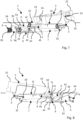
- FIGS 1 and 2 show a vehicle door handle assembly 1 in a rest position.
- the vehicle door handle assembly 1 comprises a bracket 10 and a handle 2.
- the bracket 10 is designed to be fixed on the vehicle door (not represented). In this rest position, the handle 2 is retracted into the bracket 10 in order to be at the same level of the door body when installed.
- the handle 2 comprises a first extremity 22 and a second extremity 23 opposed to the first extremity 22.
- the first extremity 22 of the handle 2 is connected to a first lever 3 and the second extremity 23 of the handle 2 is connected to a second lever 4.
- the first lever 3 is also designed to be connected to an opening lever (not represented) to open a latch of the vehicle door.
- the first lever 3 is designed to rotate between a rest position (represented in figures 1 and 2 ) where the first extremity 22 of the handle 2 is in a rest position, a deployed position (represented in figures 3 to 6 ) where the first extremity 22 of the handle 2 is in a deployed position outside the bracket 10 and an opening position (represented on figures 7 and 8 ) where the first lever 3 actuates the opening lever.
- the first lever 3 comprises a pivot connection 33 with the bracket 10 around which the first lever 3 rotates between its different positions.
- a first extremity of the first lever 3 is connected to the first extremity 22 of the handle 2 and a second extremity of the first lever 3, is connected to the opening lever, in particular, thanks to a pivot connection 31 and the shape of the first lever 3, the first lever 3 can touch the opening lever during the movement.
- the connection between the first lever 3 and the first extremity 22 of the handle is preferably a pivot-slide connection.
- the first extremity 22 of the handle 2 comprises a slide opening 21 and the first lever 3 comprises a recess 31 for example to receive a pin (not represented).
- the first lever 3 may also comprises an elastic mean 34 passively bringing back said first lever 3 from its deployed position to its rest position.
- This elastic mean 34 may be a spring positioned for example on the pivot connection 33 between the first lever 3 and the bracket 10.
- the torque applied by this elastic mean 34 is represented by a grey arrow in figures 1 to 8 .
- the second extremity 23 of the handle 2 is connected to a second lever 4.
- the second lever 4 is designed to rotate between a rest position (represented in figures 1 and 2 ) where the second extremity 23 of the handle 2 is in a rest position, an activation position (represented in figures 3 and 4 ) where the second extremity 23 of the handle 2 is pushed into the bracket 10, and a deployed position (represented in figures 5 to 8 ) where the second extremity 23 of the handle 2 is in a deployed position outside the bracket 10.
- the second lever 4 comprises a pivot connection 41 with the bracket 10 around which the second lever 4 rotates between its different positions.
- a first extremity of the second lever 4 is connected to the second extremity 23 of the handle 2.
- This connection is preferably a pivot connection 24.
- the second lever 4 may also comprises an elastic mean (not represented) passively rotating said second lever 4 to its deployed position.
- This elastic mean may be a spring positioned for example on the pivot connection 41 between the second lever 4 and the bracket 10.
- the torque applied by this elastic mean is represented by a grey arrow in figures 1 to 8 .
- the first 3 and second 4 levers may be connected together with at least one first rod 7 in order to synchronize the movements of the two levers 3, 4. More exactly, the first rod 7 transmits the rotation of the second lever 4 from its activation position to its deployed position to the first lever 3, rotating said first lever 3 from its rest position to its deployed position.
- the first rod 7 may comprises a pivot-slide connection with anyone of the first 3 or second lever 4 so that the first lever 3 can rotate from its rest position to its deployed position or from its deployed position to its opening position without rotating the second lever 4.
- the first rod 7 comprises a first extremity connected to a second extremity of the first lever 3 by a pivot connection 32.
- the first rod 7 comprises a second extremity connected to the second lever 4 by pivot-slide connection.
- the second extremity of the first rod 7 comprises a slide 71 and the second extremity of the second lever 4 comprises a pin 42 inserted into said slide 71.
- the handle 2, the first lever 3, the second 4 lever and the first rod 7 are designed and connected like a parallelogram and move together synchronously.
- the other connection of the first rod 7 with anyone of the first 3 or second lever 4 is preferably a pivot connection.
- the vehicle door handle assembly 1 also comprises a return lever 5 having a first extremity connected to a second extremity of the second lever 4, said return lever 5 being designed to rotate between a first position (represented in figures 1 and 2 ) and a second position (represented in figures 3 to 8 ). More precisely, the return lever 5 comprises a pivot connection 55 with the bracket 10 around which the return lever 5 rotates between its different positions.
- the return lever 5 also comprises an elastic mean 56 passively bringing back said return lever 5 to its first position.
- This elastic mean 56 may be a spring positioned for example on the pivot connection 55 between the return lever 5 and the bracket 10. The torque applied by this elastic mean 56 is represented by a grey arrow on figures 1 to 8 .
- the rotation of the second lever 4 to its activation position actuates the rotation of the return lever 5 from its first to its second position.
- the passive rotation of the return lever 5 from its second to its first position actuates the rotation of the second lever 4 from its deployed position to its rest position.
- the second 4 and the return 5 levers are connected together by a second 8 and a third 9 rods.
- the second rod 8 transmits the rotation of the second lever 4 from its rest position to its activation position to the return lever 5, rotating said return lever 5 from its first position to its second position.
- the third rod 9 transmits the rotation of the return lever 5 from its second position to its first position to the second lever 4, rotating said second lever 4 from its deployed position to its rest position.
- the second 8 and the third 9 rods are placed on the return lever 5 on either side of the pivot connection 55 of the return lever 5 with the bracket 10.
- the second 8 and the third 9 rods are placed on the first extremity of second lever 5 on the same side of the pivot connection 41 of the second lever 4 with the bracket 10.
- the second rod 8 may comprises a pivot-slide connection 52 with anyone of the second lever 4 or return lever 5.
- the pivot-slide connection 52 is placed between the return lever 5 and the second rod 8.
- the return lever 5 comprises the slide of said pivot-slide connection 52 and the second rod 8 comprises a pin inserted in the slide.
- the connection between the second rod 8 and the second lever 4 is a pivot connection 44.
- the other connection of the second rod 8 with any of the second lever 4 or return lever 5 is preferably a pivot connection.
- the third rod 9 may comprises a pivot-slide connection 45 with any of the second lever 4 or return lever 5.
- the pivot-slide connection 45 is placed between the second lever 4 and the third rod 9.
- the second lever 4 comprises the slide of said pivot-slide connection 45 and the third rod 9 comprises a pin inserted in the slide.
- the connection between the third rod 9 and the return lever 5 is a pivot connection 53.
- the other connection of the third rod 9 with any of the second lever 4 or return lever 5 is preferably a pivot connection.
- the return lever 5, more exactly its second extremity, is connected to a delay element 6 which slows down the passive rotation of the return lever 5 from its second to its first position.
- This delay element 6 may comprises at least one damper as illustrated in figures 1 to 8 .
- the at least one damper 6 may comprises a gearwheel 61 and the extremity of the return lever 5, connected to the at least one damper 6, comprises an arc portion with teeth 54 engaged with said gearwheel 61.
- the torque applied by this at least one damper 6 is represented by a grey arrow on figures 1 to 8 .
- the figures 1 to 8 represent different positions and cinematic steps of the deployment, opening and retractation of the handle 2.
- figures 1 and 2 are a representation of a rest position where the handle 2 is retracted into the bracket 10 in order to be at the same level of the door body when installed.
- the first lever 3 is in its rest position and maintained in this rest position by the elastic mean 34.
- the second lever 4 is in its rest position and the return lever 5 is in its first position.
- the return lever 5 is maintained in its first position by the elastic mean 56.
- the elastic mean 56 of the return lever 5 is stronger than the elastic mean of the second lever 4 in order that the return lever 5 in its first position maintained the second lever 4 in its rest position.
- the elastic mean 56 of the return lever 5 is also stronger than the delay element 6 in order to maintain the return lever 5 in its first position.
- the inside of the handle 2 may also rests on a rest portion 11 of the bracket 10 placed between the first 22 and second 23 extremities of the handle 2.
- Figures 3 and 4 represent an activation position of the handle 2 where the user activates the handle 2 by pushing the second extremity 23 of the handle 2 into the bracket 10. Due to this push, the handle 2 rotates taking support on the rest portion 11 of the bracket 10. The first extremity 22 of the handle 2 protrudes from the bracket 10 and rotates the first lever 3 around its pivot connection 33 with the bracket 10 from its rest position to an intermediate. The rotation of the first lever 3 is not transmitted to the second lever 4 by the first rod 7 due to the pivot-slide connection of the first rod 7 with anyone of the first 3 or second lever 4.
- the push of the second extremity 23 of the handle 2 rotates the second lever 4 around its pivot connection 41 with the bracket 10 from its rest position to its activation position.
- the rotation of the second lever 4 causes the rotation of the return lever 5 around its pivot connection 55 with the bracket 10 from its first to its second position.
- the transmission of the rotation of the second lever 4 to the return lever 5 is made by the second rod 8 which pushes one side of the return lever 5 causing its rotation.
- the rotation of the second lever 4 to its activation position makes the second rod 8 slid in its slide-pivot connection with anyone of the second 4 or return lever 5 bringing the second rod 8 to abutment pushing the return lever 5.
- the third rod 9 slides in its slide-pivot connection with anyone of the second lever 4 or return lever 5 without affecting the rotation of anyone of these levers 4, 5.
- the rotation of the second lever 4 is made against the torque of its elastic mean and the rotation of the return lever 5 is made against the torque of its elastic mean 56.
- Figures 5 and 6 represent a deployed position of the handle 2 where the first lever 3 is still in its deployed position and where the second lever 4 has rotated from its activation position to its deployed position, bringing the second extremity 23 of the handle 2 in its deployed position outside the bracket 10.
- the elastic mean of the second lever 4 allows the passive rotation of the second lever 4 to its deployed position.
- the rotation of the second lever 4 is not transmitted to the return lever 5 by any of the second 8 or third rod 9 which slide with their pivot-slide connections.
- the first lever 3 is maintained in its deployed position due to the first rod 7 which is in abutment with its pivot-slide connection.
- the return lever 5 is still on its second position due to the delay element 6.
- the third rod 9 is in abutment in order to stop the rotation of the second lever 4 in its deployed position against the torque of its elastic mean 34.
- Figures 7 and 8 represent an opening position of the handle where the user can grab the handle and pull it or has taken the handle and pulled it in order to open the vehicle door.
- the handle 2 rotates around the pivot connection 24 between the second extremity 23 of the handle 2 and the second lever 4.
- the first extremity 22 of the handle 2 is pulled in an opening position rotating the first lever 3 from its deployed position to its opening position.
- the rotation of the first lever 3 is not transmitted to the second lever 4 by the first rod 7 due to its pivot-slide connection.
- the first lever 3 rotates back to its deployed position due to its elastic mean 34.
- the delay element 6 slows down the passive return rotation of the return lever 5 from its second position to its first position.
- the return lever 5 rotates from its second to its first position, it also transmits its rotation to the second lever 4 in order to rotate the second lever 4 from its deployed position to its rest position.
- the third rod 9 is in abutment in order to pull back the second lever 4 in its rest position against the torque of the elastic mean of the second lever4.
- the rotation of the second 4 and the first 3 levers to their rest position are synchronous due to the first rod 7.
- the handle 2 translates from its deployed position ( figures 5 and 6 ) to its rest position ( figures 1 and 2 ). This translation is slowed down and progressive thanks to the delay element 6.
- the extremity of the return lever 5 connected to the at least one damper 6 may comprises a portion without teeth 54 in order to disconnect the return lever 5 of the at least one damper 6 before said return lever 5 reaches its first position.
- This embodiment allows accelerating the return of the return lever 5 at the end and so accelerating the translation of the handle 2 from its deployed position to its rest position when the handle 2 is near its rest position.
Landscapes
- Lock And Its Accessories (AREA)
Claims (12)
- Ensemble poignée de porte de véhicule (1) comprenant un support (10) et une poignée (2), ladite poignée (2) comprenant une première extrémité (22) et une deuxième extrémité (23) opposée à la première extrémité (22),la première extrémité (22) étant connectée à un premier levier (3), ledit premier levier (3) étant conçu pour être connecté à un levier d'ouverture afin d'ouvrir un verrou de la porte de véhicule, ledit premier levier (3) étant conçu pour entrer en rotation entre une position de repos où la première extrémité (22) de la poignée (2) est dans une position de repos, une position déployée où la première extrémité (22) de la poignée (2) est dans une position déployée à l'extérieur du support (10) et une position d'ouverture où le premier levier (3) actionne le levier d'ouverture,la deuxième extrémité (23) étant connectée à un deuxième levier (4), ledit deuxième levier (4) étant conçu pour entrer en rotation entre une position de repos où la deuxième extrémité (23) de la poignée (2) est une position de repos, une position d'activation où la deuxième extrémité (23) de la poignée (2) est poussée jusque dans le support (10), et une position déployée où la deuxième extrémité (23) de la poignée (2) est dans une position déployée à l'extérieur du support (10),l'ensemble poignée de porte de véhicule (1) comprenant également un levier de retour (5) ayant une première extrémité connectée au deuxième levier (4) par une deuxième (8) et une troisième (9) tiges, ledit levier de retour (5) étant conçu pour entrer en rotation entre une première position et une deuxième position, le levier de retour (5) comprenant un moyen élastique (56) ramenant passivement ledit levier de retour (5) dans sa première position,la rotation du deuxième levier (4) vers sa position d'activation est transmise par la deuxième tige (8) au levier de retour (5) et actionne la rotation du levier de retour (5) de sa première à sa deuxième position, etla rotation passive du levier de retour (5) de sa deuxième à sa première position est transmise par la troisième tige (9) au deuxième levier (4) et actionne la rotation du deuxième levier (4) de sa position déployée à sa position de repos.
- Ensemble poignée de porte de véhicule (1) selon la revendication précédente, dans lequel le levier de retour (5) est connecté à un élément de retard (6) qui ralentit la rotation passive du levier de retour (5) de sa deuxième à sa première position.
- Ensemble poignée de porte de véhicule (1) selon la revendication précédente, dans lequel l'élément de retard (6) comprend au moins un amortisseur.
- Ensemble poignée de porte de véhicule (1) selon la revendication précédente, dans lequel l'au moins un amortisseur (6) comprend une roue dentée (61) et dans lequel une deuxième extrémité du levier de retour (5) connectée à l'au moins un amortisseur (6) comprend une portion d'arc avec des dents (54) en prise avec ladite roue dentée (61).
- Ensemble poignée de porte de véhicule (1) selon la revendication précédente, dans lequel la deuxième extrémité du levier de retour (5) connectée à l'au moins un amortisseur (6) comprend une portion dépourvue de dents (54) afin de déconnecter le levier de retour (5) de l'au moins un amortisseur (6) avant que ledit levier de retour (5) n'atteigne sa première position.
- Ensemble poignée de porte de véhicule (1) selon l'une quelconque des revendications précédentes, dans lequel le premier levier (3) comprend un moyen élastique (34) ramenant passivement ledit premier levier (3) de sa position déployée à sa position de repos.
- Ensemble poignée de porte de véhicule (1) selon l'une quelconque des revendications précédentes, dans lequel le deuxième levier (4) comprend un moyen élastique faisant entrer en rotation passivement ledit deuxième levier (4) vers sa position déployée.
- Ensemble poignée de porte de véhicule (1) selon l'une quelconque des revendications précédentes, dans lequel la connexion entre le premier levier (3) et la première extrémité (22) de la poignée est une connexion pivot-glissière.
- Ensemble poignée de porte de véhicule (1) selon l'une quelconque des revendications précédentes, dans lequel les premier (3) et deuxième (4) leviers sont connectés ensemble par au moins une première tige (7), ladite première tige (7) transmettant la rotation du deuxième levier (4) de sa position d'activation à sa position déployée au premier levier (3), faisant entrer en rotation ledit premier levier (3) de sa position de repos à sa position déployée.
- Ensemble poignée de porte de véhicule (1) selon la revendication précédente, dans lequel la première tige (7) comprend une connexion pivot-glissière avec l'un quelconque du premier (3) ou du deuxième levier (4) de sorte que le premier levier (3) puisse entrer en rotation de sa position de repos à sa position déployée ou de sa position déployée à sa position d'ouverture sans faire entrer en rotation le deuxième levier (4).
- Ensemble poignée de porte de véhicule (1) selon l'une quelconque des revendications précédentes, dans lequel la deuxième tige (8) comprend une connexion pivot-glissière avec l'un quelconque du deuxième levier (4) ou du levier de retour (5).
- Ensemble poignée de porte de véhicule (1) selon l'une quelconque des revendications précédentes, dans lequel la troisième tige (9) comprend une connexion pivot-glissière avec l'un quelconque du deuxième levier (4) ou du levier de retour (5).
Priority Applications (8)
| Application Number | Priority Date | Filing Date | Title |
|---|---|---|---|
| EP22158287.7A EP4234858B1 (fr) | 2022-02-23 | 2022-02-23 | Ensemble poignée de porte de véhicule |
| EP22191999.6A EP4234859B1 (fr) | 2022-02-23 | 2022-08-24 | Ensemble poignée de porte de véhicule |
| ES23152938T ES3022683T3 (en) | 2022-02-23 | 2023-01-23 | Vehicle door handle assembly |
| EP23152938.9A EP4234860B1 (fr) | 2022-02-23 | 2023-01-23 | Ensemble poignée de porte de véhicule |
| CN202310141515.2A CN116641605A (zh) | 2022-02-23 | 2023-02-20 | 车门把手组件 |
| US18/173,220 US12385298B2 (en) | 2022-02-23 | 2023-02-23 | Vehicle door handle assembly |
| CN202310155971.2A CN116641607A (zh) | 2022-02-23 | 2023-02-23 | 车门把手组件 |
| US18/113,145 US12286821B2 (en) | 2022-02-23 | 2023-02-23 | Vehicle door handle assembly |
Applications Claiming Priority (1)
| Application Number | Priority Date | Filing Date | Title |
|---|---|---|---|
| EP22158287.7A EP4234858B1 (fr) | 2022-02-23 | 2022-02-23 | Ensemble poignée de porte de véhicule |
Publications (2)
| Publication Number | Publication Date |
|---|---|
| EP4234858A1 EP4234858A1 (fr) | 2023-08-30 |
| EP4234858B1 true EP4234858B1 (fr) | 2025-04-09 |
Family
ID=80448623
Family Applications (2)
| Application Number | Title | Priority Date | Filing Date |
|---|---|---|---|
| EP22158287.7A Active EP4234858B1 (fr) | 2022-02-23 | 2022-02-23 | Ensemble poignée de porte de véhicule |
| EP22191999.6A Active EP4234859B1 (fr) | 2022-02-23 | 2022-08-24 | Ensemble poignée de porte de véhicule |
Family Applications After (1)
| Application Number | Title | Priority Date | Filing Date |
|---|---|---|---|
| EP22191999.6A Active EP4234859B1 (fr) | 2022-02-23 | 2022-08-24 | Ensemble poignée de porte de véhicule |
Country Status (3)
| Country | Link |
|---|---|
| US (1) | US12385298B2 (fr) |
| EP (2) | EP4234858B1 (fr) |
| CN (1) | CN116641605A (fr) |
Families Citing this family (1)
| Publication number | Priority date | Publication date | Assignee | Title |
|---|---|---|---|---|
| US20250215731A1 (en) * | 2023-12-28 | 2025-07-03 | Sl Corporation | Door handle for vehicle |
Family Cites Families (11)
| Publication number | Priority date | Publication date | Assignee | Title |
|---|---|---|---|---|
| US7210716B2 (en) * | 2004-06-03 | 2007-05-01 | Illinois Tool Works Inc. | Movement prevention device |
| DE102013112705A1 (de) * | 2013-11-18 | 2015-05-21 | Illinois Tool Works Inc. | System aus einem Bauteil und einer Betätigungsvorrichtung für das Bauteil |
| GB2536672B (en) * | 2015-03-25 | 2018-04-04 | Jaguar Land Rover Ltd | Rectractable handle arrangement with emergency manual deployment |
| JP6617498B2 (ja) * | 2015-09-28 | 2019-12-11 | アイシン精機株式会社 | 車両用アウトサイドハンドル装置 |
| FR3054260B1 (fr) * | 2016-07-22 | 2018-07-13 | Peugeot Citroen Automobiles Sa | Systeme de commande d’ouverture d’ouvrant de vehicule automobile |
| JP6957390B2 (ja) * | 2018-03-09 | 2021-11-02 | 株式会社アルファ | 車両のドアハンドル装置 |
| US10435924B1 (en) * | 2018-06-26 | 2019-10-08 | Ford Global Technologies, Llc | Vehicle door handle having ice handling |
| KR102621229B1 (ko) * | 2018-08-31 | 2024-01-04 | 현대자동차 주식회사 | 차량용 출몰형 아웃사이드 도어 핸들 조립체 |
| KR102104888B1 (ko) * | 2019-01-24 | 2020-04-27 | 주식회사 프라코 | 차량용 오토 플러쉬 아웃사이드 도어 핸들 조립체 |
| KR20210055107A (ko) * | 2019-10-14 | 2021-05-17 | 주식회사 세화오토모티브 | 차량의 출몰형 아웃사이드 도어 핸들 |
| US11746575B2 (en) * | 2020-07-16 | 2023-09-05 | Magna Mirrors Of America, Inc. | Vehicular door handle with manual override stop |
-
2022
- 2022-02-23 EP EP22158287.7A patent/EP4234858B1/fr active Active
- 2022-08-24 EP EP22191999.6A patent/EP4234859B1/fr active Active
-
2023
- 2023-02-20 CN CN202310141515.2A patent/CN116641605A/zh active Pending
- 2023-02-23 US US18/173,220 patent/US12385298B2/en active Active
Also Published As
| Publication number | Publication date |
|---|---|
| CN116641605A (zh) | 2023-08-25 |
| EP4234859B1 (fr) | 2025-03-19 |
| US20230265692A1 (en) | 2023-08-24 |
| EP4234859A1 (fr) | 2023-08-30 |
| US12385298B2 (en) | 2025-08-12 |
| EP4234858A1 (fr) | 2023-08-30 |
Similar Documents
| Publication | Publication Date | Title |
|---|---|---|
| CN110626223B (zh) | 一种电动滑轨的离合机构 | |
| JP6629724B2 (ja) | ドアハンドルとドアハンドル用の作動装置とから構成されるシステム | |
| CN110295807B (zh) | 具有紧急机械解锁的打开控制装置 | |
| US6067869A (en) | Actuating assembly for motor-vehicle door latch | |
| CN107719677B (zh) | 飞机座椅自动释放装置 | |
| EP2709865B1 (fr) | Dispositif électrique d'ouverture de porte | |
| CN112639240A (zh) | 用于车辆的嵌装式门把手组件的联接装置 | |
| EP4234858B1 (fr) | Ensemble poignée de porte de véhicule | |
| EP4234860B1 (fr) | Ensemble poignée de porte de véhicule | |
| US20250059804A1 (en) | Combined motor vehicle lock | |
| EP3943695A1 (fr) | Poignée pour une portière de véhicule | |
| EP3783173B1 (fr) | Porte de véhicule avec dispositif de serrure électrique pour enfant | |
| CN109281557B (zh) | 一种吸合解锁控制装置 | |
| CN218085185U (zh) | 滑轨组件、车辆座椅及车辆 | |
| US9677316B2 (en) | Motorized device for opening and/or closing an aircraft door | |
| WO2011148691A1 (fr) | Dispositif coulissant à commande électrique | |
| US20240044183A1 (en) | Motor vehicle latch | |
| EP4414526A1 (fr) | Ensemble poignée de porte de véhicule | |
| EP4407128A1 (fr) | Ensemble poignée de porte de véhicule électrique | |
| EP4353931A1 (fr) | Ensemble poignée de porte de véhicule avec un amortisseur | |
| US20240003169A1 (en) | Closing device for a motor vehicle lock | |
| EP2886405A1 (fr) | Levier de frein à main avec actuation électrique | |
| CN116587936A (zh) | 滑动机构、车辆座椅及车辆 | |
| EP4414527B1 (fr) | Ensemble poignée de porte de véhicule | |
| CN110593679B (zh) | 一种用于轨道交通车辆门系统的锁闭机构 |
Legal Events
| Date | Code | Title | Description |
|---|---|---|---|
| PUAI | Public reference made under article 153(3) epc to a published international application that has entered the european phase |
Free format text: ORIGINAL CODE: 0009012 |
|
| STAA | Information on the status of an ep patent application or granted ep patent |
Free format text: STATUS: THE APPLICATION HAS BEEN PUBLISHED |
|
| AK | Designated contracting states |
Kind code of ref document: A1 Designated state(s): AL AT BE BG CH CY CZ DE DK EE ES FI FR GB GR HR HU IE IS IT LI LT LU LV MC MK MT NL NO PL PT RO RS SE SI SK SM TR |
|
| STAA | Information on the status of an ep patent application or granted ep patent |
Free format text: STATUS: REQUEST FOR EXAMINATION WAS MADE |
|
| 17P | Request for examination filed |
Effective date: 20240209 |
|
| RBV | Designated contracting states (corrected) |
Designated state(s): AL AT BE BG CH CY CZ DE DK EE ES FI FR GB GR HR HU IE IS IT LI LT LU LV MC MK MT NL NO PL PT RO RS SE SI SK SM TR |
|
| RAP3 | Party data changed (applicant data changed or rights of an application transferred) |
Owner name: MINEBEA ACCESSSOLUTIONS ITALIA S.P.A. |
|
| GRAP | Despatch of communication of intention to grant a patent |
Free format text: ORIGINAL CODE: EPIDOSNIGR1 |
|
| STAA | Information on the status of an ep patent application or granted ep patent |
Free format text: STATUS: GRANT OF PATENT IS INTENDED |
|
| INTG | Intention to grant announced |
Effective date: 20241209 |
|
| GRAS | Grant fee paid |
Free format text: ORIGINAL CODE: EPIDOSNIGR3 |
|
| GRAA | (expected) grant |
Free format text: ORIGINAL CODE: 0009210 |
|
| STAA | Information on the status of an ep patent application or granted ep patent |
Free format text: STATUS: THE PATENT HAS BEEN GRANTED |
|
| AK | Designated contracting states |
Kind code of ref document: B1 Designated state(s): AL AT BE BG CH CY CZ DE DK EE ES FI FR GB GR HR HU IE IS IT LI LT LU LV MC MK MT NL NO PL PT RO RS SE SI SK SM TR |
|
| REG | Reference to a national code |
Ref country code: GB Ref legal event code: FG4D |
|
| REG | Reference to a national code |
Ref country code: CH Ref legal event code: EP |
|
| REG | Reference to a national code |
Ref country code: DE Ref legal event code: R096 Ref document number: 602022012756 Country of ref document: DE |
|
| REG | Reference to a national code |
Ref country code: IE Ref legal event code: FG4D |
|
| REG | Reference to a national code |
Ref country code: NL Ref legal event code: MP Effective date: 20250409 |
|
| PG25 | Lapsed in a contracting state [announced via postgrant information from national office to epo] |
Ref country code: NL Free format text: LAPSE BECAUSE OF FAILURE TO SUBMIT A TRANSLATION OF THE DESCRIPTION OR TO PAY THE FEE WITHIN THE PRESCRIBED TIME-LIMIT Effective date: 20250409 |
|
| REG | Reference to a national code |
Ref country code: AT Ref legal event code: MK05 Ref document number: 1783644 Country of ref document: AT Kind code of ref document: T Effective date: 20250409 |
|
| PG25 | Lapsed in a contracting state [announced via postgrant information from national office to epo] |
Ref country code: FI Free format text: LAPSE BECAUSE OF FAILURE TO SUBMIT A TRANSLATION OF THE DESCRIPTION OR TO PAY THE FEE WITHIN THE PRESCRIBED TIME-LIMIT Effective date: 20250409 Ref country code: ES Free format text: LAPSE BECAUSE OF FAILURE TO SUBMIT A TRANSLATION OF THE DESCRIPTION OR TO PAY THE FEE WITHIN THE PRESCRIBED TIME-LIMIT Effective date: 20250409 Ref country code: PT Free format text: LAPSE BECAUSE OF FAILURE TO SUBMIT A TRANSLATION OF THE DESCRIPTION OR TO PAY THE FEE WITHIN THE PRESCRIBED TIME-LIMIT Effective date: 20250811 |
|
| REG | Reference to a national code |
Ref country code: LT Ref legal event code: MG9D |
|
| PG25 | Lapsed in a contracting state [announced via postgrant information from national office to epo] |
Ref country code: GR Free format text: LAPSE BECAUSE OF FAILURE TO SUBMIT A TRANSLATION OF THE DESCRIPTION OR TO PAY THE FEE WITHIN THE PRESCRIBED TIME-LIMIT Effective date: 20250710 Ref country code: NO Free format text: LAPSE BECAUSE OF FAILURE TO SUBMIT A TRANSLATION OF THE DESCRIPTION OR TO PAY THE FEE WITHIN THE PRESCRIBED TIME-LIMIT Effective date: 20250709 |
|
| PG25 | Lapsed in a contracting state [announced via postgrant information from national office to epo] |
Ref country code: PL Free format text: LAPSE BECAUSE OF FAILURE TO SUBMIT A TRANSLATION OF THE DESCRIPTION OR TO PAY THE FEE WITHIN THE PRESCRIBED TIME-LIMIT Effective date: 20250409 |
|
| PG25 | Lapsed in a contracting state [announced via postgrant information from national office to epo] |
Ref country code: BG Free format text: LAPSE BECAUSE OF FAILURE TO SUBMIT A TRANSLATION OF THE DESCRIPTION OR TO PAY THE FEE WITHIN THE PRESCRIBED TIME-LIMIT Effective date: 20250409 |
|
| PG25 | Lapsed in a contracting state [announced via postgrant information from national office to epo] |
Ref country code: HR Free format text: LAPSE BECAUSE OF FAILURE TO SUBMIT A TRANSLATION OF THE DESCRIPTION OR TO PAY THE FEE WITHIN THE PRESCRIBED TIME-LIMIT Effective date: 20250409 |
|
| PG25 | Lapsed in a contracting state [announced via postgrant information from national office to epo] |
Ref country code: AT Free format text: LAPSE BECAUSE OF FAILURE TO SUBMIT A TRANSLATION OF THE DESCRIPTION OR TO PAY THE FEE WITHIN THE PRESCRIBED TIME-LIMIT Effective date: 20250409 |
|
| PG25 | Lapsed in a contracting state [announced via postgrant information from national office to epo] |
Ref country code: RS Free format text: LAPSE BECAUSE OF FAILURE TO SUBMIT A TRANSLATION OF THE DESCRIPTION OR TO PAY THE FEE WITHIN THE PRESCRIBED TIME-LIMIT Effective date: 20250709 |
|
| PG25 | Lapsed in a contracting state [announced via postgrant information from national office to epo] |
Ref country code: IS Free format text: LAPSE BECAUSE OF FAILURE TO SUBMIT A TRANSLATION OF THE DESCRIPTION OR TO PAY THE FEE WITHIN THE PRESCRIBED TIME-LIMIT Effective date: 20250809 |
|
| PG25 | Lapsed in a contracting state [announced via postgrant information from national office to epo] |
Ref country code: LV Free format text: LAPSE BECAUSE OF FAILURE TO SUBMIT A TRANSLATION OF THE DESCRIPTION OR TO PAY THE FEE WITHIN THE PRESCRIBED TIME-LIMIT Effective date: 20250409 |
|
| REG | Reference to a national code |
Ref country code: DE Ref legal event code: R097 Ref document number: 602022012756 Country of ref document: DE |
|
| PG25 | Lapsed in a contracting state [announced via postgrant information from national office to epo] |
Ref country code: DK Free format text: LAPSE BECAUSE OF FAILURE TO SUBMIT A TRANSLATION OF THE DESCRIPTION OR TO PAY THE FEE WITHIN THE PRESCRIBED TIME-LIMIT Effective date: 20250409 Ref country code: SM Free format text: LAPSE BECAUSE OF FAILURE TO SUBMIT A TRANSLATION OF THE DESCRIPTION OR TO PAY THE FEE WITHIN THE PRESCRIBED TIME-LIMIT Effective date: 20250409 |
|
| PG25 | Lapsed in a contracting state [announced via postgrant information from national office to epo] |
Ref country code: CZ Free format text: LAPSE BECAUSE OF FAILURE TO SUBMIT A TRANSLATION OF THE DESCRIPTION OR TO PAY THE FEE WITHIN THE PRESCRIBED TIME-LIMIT Effective date: 20250409 |
|
| PG25 | Lapsed in a contracting state [announced via postgrant information from national office to epo] |
Ref country code: EE Free format text: LAPSE BECAUSE OF FAILURE TO SUBMIT A TRANSLATION OF THE DESCRIPTION OR TO PAY THE FEE WITHIN THE PRESCRIBED TIME-LIMIT Effective date: 20250409 |
|
| PG25 | Lapsed in a contracting state [announced via postgrant information from national office to epo] |
Ref country code: SK Free format text: LAPSE BECAUSE OF FAILURE TO SUBMIT A TRANSLATION OF THE DESCRIPTION OR TO PAY THE FEE WITHIN THE PRESCRIBED TIME-LIMIT Effective date: 20250409 |
|
| PG25 | Lapsed in a contracting state [announced via postgrant information from national office to epo] |
Ref country code: IT Free format text: LAPSE BECAUSE OF FAILURE TO SUBMIT A TRANSLATION OF THE DESCRIPTION OR TO PAY THE FEE WITHIN THE PRESCRIBED TIME-LIMIT Effective date: 20250409 |
|
| PLBE | No opposition filed within time limit |
Free format text: ORIGINAL CODE: 0009261 |
|
| STAA | Information on the status of an ep patent application or granted ep patent |
Free format text: STATUS: NO OPPOSITION FILED WITHIN TIME LIMIT |
|
| REG | Reference to a national code |
Ref country code: CH Ref legal event code: L10 Free format text: ST27 STATUS EVENT CODE: U-0-0-L10-L00 (AS PROVIDED BY THE NATIONAL OFFICE) Effective date: 20260218 |
|
| 26N | No opposition filed |
Effective date: 20260112 |
|
| PGFP | Annual fee paid to national office [announced via postgrant information from national office to epo] |
Ref country code: DE Payment date: 20260206 Year of fee payment: 5 |
|
| PGFP | Annual fee paid to national office [announced via postgrant information from national office to epo] |
Ref country code: FR Payment date: 20260227 Year of fee payment: 5 |