EP4234909A1 - Verfahren zur steuerung des gemischverhältnisses des kraftstoffgemischs einer brennkraftmaschine eines kraftfahrzeugs - Google Patents
Verfahren zur steuerung des gemischverhältnisses des kraftstoffgemischs einer brennkraftmaschine eines kraftfahrzeugs Download PDFInfo
- Publication number
- EP4234909A1 EP4234909A1 EP23156550.8A EP23156550A EP4234909A1 EP 4234909 A1 EP4234909 A1 EP 4234909A1 EP 23156550 A EP23156550 A EP 23156550A EP 4234909 A1 EP4234909 A1 EP 4234909A1
- Authority
- EP
- European Patent Office
- Prior art keywords
- engine
- variable
- fuel
- timing system
- richness
- Prior art date
- Legal status (The legal status is an assumption and is not a legal conclusion. Google has not performed a legal analysis and makes no representation as to the accuracy of the status listed.)
- Granted
Links
Images


Classifications
-
- F—MECHANICAL ENGINEERING; LIGHTING; HEATING; WEAPONS; BLASTING
- F02—COMBUSTION ENGINES; HOT-GAS OR COMBUSTION-PRODUCT ENGINE PLANTS
- F02D—CONTROLLING COMBUSTION ENGINES
- F02D41/00—Electrical control of supply of combustible mixture or its constituents
- F02D41/02—Circuit arrangements for generating control signals
- F02D41/18—Circuit arrangements for generating control signals by measuring intake air flow
- F02D41/182—Circuit arrangements for generating control signals by measuring intake air flow for the control of a fuel injection device
-
- F—MECHANICAL ENGINEERING; LIGHTING; HEATING; WEAPONS; BLASTING
- F02—COMBUSTION ENGINES; HOT-GAS OR COMBUSTION-PRODUCT ENGINE PLANTS
- F02D—CONTROLLING COMBUSTION ENGINES
- F02D13/00—Controlling the engine output power by varying inlet or exhaust valve operating characteristics, e.g. timing
- F02D13/02—Controlling the engine output power by varying inlet or exhaust valve operating characteristics, e.g. timing during engine operation
- F02D13/0223—Variable control of the intake valves only
-
- F—MECHANICAL ENGINEERING; LIGHTING; HEATING; WEAPONS; BLASTING
- F02—COMBUSTION ENGINES; HOT-GAS OR COMBUSTION-PRODUCT ENGINE PLANTS
- F02D—CONTROLLING COMBUSTION ENGINES
- F02D13/00—Controlling the engine output power by varying inlet or exhaust valve operating characteristics, e.g. timing
- F02D13/02—Controlling the engine output power by varying inlet or exhaust valve operating characteristics, e.g. timing during engine operation
- F02D13/0242—Variable control of the exhaust valves only
-
- F—MECHANICAL ENGINEERING; LIGHTING; HEATING; WEAPONS; BLASTING
- F02—COMBUSTION ENGINES; HOT-GAS OR COMBUSTION-PRODUCT ENGINE PLANTS
- F02D—CONTROLLING COMBUSTION ENGINES
- F02D41/00—Electrical control of supply of combustible mixture or its constituents
- F02D41/02—Circuit arrangements for generating control signals
- F02D41/14—Introducing closed-loop corrections
- F02D41/1401—Introducing closed-loop corrections characterised by the control or regulation method
-
- F—MECHANICAL ENGINEERING; LIGHTING; HEATING; WEAPONS; BLASTING
- F01—MACHINES OR ENGINES IN GENERAL; ENGINE PLANTS IN GENERAL; STEAM ENGINES
- F01L—CYCLICALLY OPERATING VALVES FOR MACHINES OR ENGINES
- F01L1/00—Valve-gear or valve arrangements, e.g. lift-valve gear
- F01L1/34—Valve-gear or valve arrangements, e.g. lift-valve gear characterised by the provision of means for changing the timing of the valves without changing the duration of opening and without affecting the magnitude of the valve lift
-
- F—MECHANICAL ENGINEERING; LIGHTING; HEATING; WEAPONS; BLASTING
- F01—MACHINES OR ENGINES IN GENERAL; ENGINE PLANTS IN GENERAL; STEAM ENGINES
- F01L—CYCLICALLY OPERATING VALVES FOR MACHINES OR ENGINES
- F01L2820/00—Details on specific features characterising valve gear arrangements
- F01L2820/04—Sensors
- F01L2820/041—Camshafts position or phase sensors
-
- F—MECHANICAL ENGINEERING; LIGHTING; HEATING; WEAPONS; BLASTING
- F02—COMBUSTION ENGINES; HOT-GAS OR COMBUSTION-PRODUCT ENGINE PLANTS
- F02D—CONTROLLING COMBUSTION ENGINES
- F02D13/00—Controlling the engine output power by varying inlet or exhaust valve operating characteristics, e.g. timing
- F02D13/02—Controlling the engine output power by varying inlet or exhaust valve operating characteristics, e.g. timing during engine operation
- F02D13/0269—Controlling the valves to perform a Miller-Atkinson cycle
-
- F—MECHANICAL ENGINEERING; LIGHTING; HEATING; WEAPONS; BLASTING
- F02—COMBUSTION ENGINES; HOT-GAS OR COMBUSTION-PRODUCT ENGINE PLANTS
- F02D—CONTROLLING COMBUSTION ENGINES
- F02D41/00—Electrical control of supply of combustible mixture or its constituents
- F02D41/0002—Controlling intake air
- F02D2041/001—Controlling intake air for engines with variable valve actuation
-
- F—MECHANICAL ENGINEERING; LIGHTING; HEATING; WEAPONS; BLASTING
- F02—COMBUSTION ENGINES; HOT-GAS OR COMBUSTION-PRODUCT ENGINE PLANTS
- F02D—CONTROLLING COMBUSTION ENGINES
- F02D41/00—Electrical control of supply of combustible mixture or its constituents
- F02D41/02—Circuit arrangements for generating control signals
- F02D41/14—Introducing closed-loop corrections
- F02D41/1401—Introducing closed-loop corrections characterised by the control or regulation method
- F02D2041/1412—Introducing closed-loop corrections characterised by the control or regulation method using a predictive controller
-
- F—MECHANICAL ENGINEERING; LIGHTING; HEATING; WEAPONS; BLASTING
- F02—COMBUSTION ENGINES; HOT-GAS OR COMBUSTION-PRODUCT ENGINE PLANTS
- F02D—CONTROLLING COMBUSTION ENGINES
- F02D41/00—Electrical control of supply of combustible mixture or its constituents
- F02D41/02—Circuit arrangements for generating control signals
- F02D41/14—Introducing closed-loop corrections
- F02D41/1401—Introducing closed-loop corrections characterised by the control or regulation method
- F02D2041/1413—Controller structures or design
- F02D2041/1431—Controller structures or design the system including an input-output delay
-
- F—MECHANICAL ENGINEERING; LIGHTING; HEATING; WEAPONS; BLASTING
- F02—COMBUSTION ENGINES; HOT-GAS OR COMBUSTION-PRODUCT ENGINE PLANTS
- F02D—CONTROLLING COMBUSTION ENGINES
- F02D2200/00—Input parameters for engine control
- F02D2200/02—Input parameters for engine control the parameters being related to the engine
- F02D2200/04—Engine intake system parameters
- F02D2200/0402—Engine intake system parameters the parameter being determined by using a model of the engine intake or its components
-
- F—MECHANICAL ENGINEERING; LIGHTING; HEATING; WEAPONS; BLASTING
- F02—COMBUSTION ENGINES; HOT-GAS OR COMBUSTION-PRODUCT ENGINE PLANTS
- F02D—CONTROLLING COMBUSTION ENGINES
- F02D2200/00—Input parameters for engine control
- F02D2200/02—Input parameters for engine control the parameters being related to the engine
- F02D2200/04—Engine intake system parameters
- F02D2200/0411—Volumetric efficiency
-
- F—MECHANICAL ENGINEERING; LIGHTING; HEATING; WEAPONS; BLASTING
- F02—COMBUSTION ENGINES; HOT-GAS OR COMBUSTION-PRODUCT ENGINE PLANTS
- F02D—CONTROLLING COMBUSTION ENGINES
- F02D2200/00—Input parameters for engine control
- F02D2200/02—Input parameters for engine control the parameters being related to the engine
- F02D2200/04—Engine intake system parameters
- F02D2200/0414—Air temperature
- F02D2200/0416—Estimation of air temperature
-
- F—MECHANICAL ENGINEERING; LIGHTING; HEATING; WEAPONS; BLASTING
- F02—COMBUSTION ENGINES; HOT-GAS OR COMBUSTION-PRODUCT ENGINE PLANTS
- F02D—CONTROLLING COMBUSTION ENGINES
- F02D41/00—Electrical control of supply of combustible mixture or its constituents
- F02D41/0025—Controlling engines characterised by use of non-liquid fuels, pluralities of fuels, or non-fuel substances added to the combustible mixtures
- F02D41/0047—Controlling exhaust gas recirculation [EGR]
- F02D41/0065—Specific aspects of external EGR control
- F02D41/0072—Estimating, calculating or determining the EGR rate, amount or flow
Definitions
- the present invention relates to the control of an internal combustion engine and more particularly of a controlled ignition engine, during a transient operating phase of the engine.
- This difference in richness is due to a poor estimation of the air flow entering the engine and can lead to an increase in polluting emissions, an increase in engine noise and/or a driving pleasure problem due to jerks.
- the driver of the vehicle determines, by actuating the accelerator pedal, a vehicle acceleration setpoint. From the acceleration setpoint and the engine speed, a computer defines an engine torque setpoint to be obtained in order to reach this acceleration setpoint.
- the torque setpoint is translated into a mass air flow setpoint Qair, into an ignition advance value AA which is chosen preferably so as to optimize the combustion efficiency, and in a richness setpoint generally equal to 1, which corresponds to the flow rate of the fuel that must be burned in stoichiometric proportions to obtain the torque while making operate a three-way catalyst of the engine in its catalytic operating range in which it is able to treat unburnt hydrocarbons, carbon monoxide and nitrogen oxides.
- AA ignition advance value
- a recirculated gas mass flow setpoint Qegr is also defined which corresponds to the recirculation rate to be applied to comply with the target fuel consumption.
- the sum of the air flow Qair and the recirculated gas flow Qegr represents the total gas mass flow Qmot entering the engine, which is generally regulated by adjusting the position of a throttle body in the air intake circuit of the engine, so as to obtain a pressure value Pcol in the engine intake manifold corresponding to the total gas flow rate sought, the recirculated gas flow rate Qegr being obtained by adjusting the position of a valve in the partial recirculation circuit, the desired air flow Qair being obtained indirectly as the difference between the total gas flow Qmot and the recirculated gas flow Qegr.
- An engine computer uses an air filling model, which makes it possible to determine the value of the minimum pressure of the intake manifold to meet the engine torque setpoint.
- filling is defined as being equal to the ratio between the mass of air actually sucked in and the mass of air which could have entered by considering only the total volume of the cylinders.
- the value of the efficiency ⁇ rdvl depends at least on the speed N and the pressure in the intake manifold Pcol.
- variable valve timing system also called VVT system, from the English acronym for: Variable Valve Timing
- VVT system from the English acronym for: Variable Valve Timing
- the efficiency ⁇ rdvl also depends on the position of this VVT system at the intake, which determines the instants of opening and closing of the intake valves in the engine's combustion cycle.
- the efficiency also depends on the position of this exhaust VVT system, which determines the times of opening and closing exhaust valves, although the sensitivity of the efficiency value to the position of the exhaust VVT system is much less than in the case of an intake VVT system.
- volumetric efficiency is mapped by preliminary tests on the bench according to these parameters: engine speed; couple ; and, position of the VVT system on intake, and the map is stored in the memory of the engine computer. It is possible for example not to take into account the position of the VVT system on the exhaust, if the engine has such a system.
- the computer determines a current value of the speed N, of the pressure in the intake manifold Pcol and of a value of the position of the VVT system at intake, then it uses the mapping to calculate the volumetric efficiency value.
- the computer also determines a current value of the temperature Tcol in the exhaust manifold. It then uses the filling model to calculate a value of the total gas flow Qmot, then a value of the air flow Qair by subtracting the flow of recirculated gases Qegr from the total gas flow Qmot.
- the recirculated gas flow Qegr can be determined, for its part, for example in a manner known per se from a Barré Saint Venant equation at the terminals of the valve of the recirculation circuit.
- the richness adjustment is generally carried out in a closed loop on a set value.
- the system measures, for example, the actual richness of the combustion gases leaving the engine using a proportional oxygen sensor located upstream of a three-way catalytic converter in the engine.
- the value of the difference in richness between the measured value and the setpoint value is sent as input to a regulator, for example of the PID (proportional, integral, derivative) type, the output value of which is a flow rate correction value of fuel which is added to a fuel flow value calculated for the open-loop servo-control, to correspond to the theoretical fuel flow allowing combustion in stoichiometric proportions.
- a regulator for example of the PID (proportional, integral, derivative) type, the output value of which is a flow rate correction value of fuel which is added to a fuel flow value calculated for the open-loop servo-control, to correspond to the theoretical fuel flow allowing combustion in stoichiometric proportions.
- the richness adjustment is obtained by adjusting the quantity of fuel injected by imposing the duration of opening of the fuel injectors of the engine.
- the quantity of fuel is the sum of a first quantity of fuel calculated in open loop from the current air flow at the rate of one gram of fuel for 14.7 grams of air, to correspond to the proportions stoichiometric, and a corrective term used for closed-loop control. THE values of the corrective term are all the smaller as the first calculated quantity is right.
- the current airflow used in the calculation of the current airflow estimate is obtained from the filling model of equation 1, which depends in particular on the pressure in the intake manifold and the position of the intake VVT system.
- the pressure Pcol in the intake manifold and the position of the VVT system at the intake generally no longer correspond to the values measured and which are used to calculate the volumetric efficiency, then the total gas flow Qmot and the air flow Qair.
- the estimate of the current air flow is distorted, and the quantity of fuel to be injected determined by open-loop calculation from the air flow no longer corresponds to the pressure measured in the intake manifold or to the measured position of the VVT system at intake and at the corresponding intake valve opening and closing times. It is then observed that the regulator, which slaves the richness value to a setpoint value (generally equal to 1) must use higher fuel quantity corrective terms to compensate for the air flow calculation error.
- the object of the invention is to improve control of the richness of the fuel mixture in the transient phases of engine operation during which the position of a variable valve timing system, and more particularly of a variable intake valve timing system, evolves between the beginning and the end of the transient phases.
- the subject of the invention is a method for controlling the richness of a fuel mixture for an internal combustion engine of a motor vehicle equipped with a variable timing system for the engine intake valves.
- the richness control method is configured to improve the precision of calculation of the quantity of fuel to be injected during transient phases of engine operation.
- the predictive calculation of the position of the variable valve timing system of the intake valves at the moment of the start of the opening of the fuel injectors makes use of a model of response to a setpoint of the valves.
- the response model of the variable valve timing system is characterized by a dead time parameter and a maximum speed of movement of the system.
- the response model of the variable valve timing system takes into account an anticipation to obtain an anticipated real position with respect to the measured position.
- the anticipation is between 30 ms and 70 ms, and is preferably equal to 50 ms.
- the engine comprises at least one partial exhaust gas recirculation circuit at the intake.
- the estimate of the fresh air flow anticipates the variation in EGR flow, by calculating the position of the EGR valve from the EGR flow setpoint and the response time in order to obtain a flow of anticipated EGR in relation to the EGR flow calculated from the position measurement of the EGR valve.
- the subject of the invention is a system for controlling the richness of a fuel mixture for an internal combustion engine of a motor vehicle equipped with a variable timing system for the valves of the engine, in particular a timing system variable at the intake of the intake valves.
- the richness control system comprises means for detecting a change in the operating point of the engine, means for calculating at least one position setpoint of the variable valve timing system, means for predicting calculation of a position the variable valve timing system, the means for estimating the air flow and the means for calculating the quantity of fuel to be injected for operation of the engine at richness 1.
- the internal combustion engine 10 is of the spark ignition type (gasoline) and comprises, in a non-limiting manner, three cylinders 12 in line, a fresh air intake manifold 14, an exhaust manifold 16, a system turbo-compression or turbocharger 18, a variable timing system 50 of the intake valves 51 of the engine and possibly also a variable timing system 52 of the exhaust valves 53 of the engine.
- the Variable Valve Timing System 50 intake valve is equipped with a sensor 54 which makes it possible to know its angular position at all times, which corresponds to determined times of opening and closing of the intake valves 51 in the combustion cycle of the engine (these times being usually measured in crankshaft degrees from a top dead center position).
- the variable timing system 52 of the exhaust valves if present, is also equipped with a sensor 55 which allows its angular position to be known at all times, which also corresponds to determined times of opening and closing. exhaust valves 53 in the engine combustion cycle.
- the cylinders 12 are supplied with air via the intake manifold 14, or distributor, itself supplied by a pipe 20 provided with an air filter 22 and a compressor 18a of the turbocharger 18 of the engine 10.
- the turbocharger 18 essentially comprises a turbine 18b driven by the exhaust gases and the compressor 18a mounted on the same shaft as the turbine 18b and providing compression of the air distributed by the air filter 22 or air box, in the purpose of increasing the quantity (mass flow) of air admitted into the cylinders 12 of the engine 10 for an identical volume flow.
- the internal combustion engine 10 comprises an intake circuit Ca and an exhaust circuit Ce.
- the compressor is associated with a bypass circuit equipped with an inlet relief valve 56 which opens in the event of sudden closing of the throttle valve 30, to prevent the compressed air, located between the compressor 18a and the throttle body 30 passes through the compressor 18a and does not damage it when, for example, the driver of the vehicle suddenly lifts his foot from the accelerator pedal.
- the latter recovers the exhaust gases resulting from combustion and evacuates the latter to the outside, via a gas exhaust duct 34 opening out at the entry of the turbine 18b of the turbocharger 18 and by an exhaust line 36 mounted downstream of the turbine 18b.
- the engine 10 further comprises a circuit 38 for partial recirculation of the exhaust gases at the intake, called the “EGR” circuit (“exhaust gas recirculation” in Anglo-Saxon terms).
- EGR exhaust gas recirculation
- the engine 10 need not be equipped with an EGR circuit, without departing from the scope of the invention.
- This circuit 38 is here in a non-limiting manner a low pressure exhaust gas recirculation circuit. It is connected to the exhaust line 36, downstream of said turbine 18b, and in particular downstream of the gas pollution control system and returns the exhaust gases to the fresh air supply pipe 20, upstream of the compressor 18a of the turbocharger 18, in particular downstream of the flow meter 26.
- the flow meter 26 only measures the flow of fresh air alone.
- this recirculation circuit 38 comprises, in the direction of circulation of the recycled gases, a cooler 38a, a filter 38b, and a valve 38c configured to regulate the flow rate of the low-pressure exhaust gases.
- Valve 38c is disposed downstream of cooler 38a and filter 38b and upstream of compressor 18a.
- the engine is associated with a fuel circuit comprising, for example, fuel injectors (not referenced) injecting gasoline directly into each cylinder from a fuel tank (not shown).
- the engine comprises an electronic control unit 70 configured to control the various elements of the internal combustion engine from data collected by sensors at various locations of the engine.
- the electronic control unit 70 comprises a calculation module 72, a measurement module 73 and a control module 74.
- Such a method is in particular implemented by the computer 70 from the measurements delivered by the various sensors of the engine and by controlling the various elements of the engine.
- the method 60 comprises a preliminary step 61 of detecting a change in the operating point of the engine 10, or operating point setpoint, in which the computer 70 detects a new operating point corresponding to a variation in the operating point of the engine 10.
- An operating point of the engine 10 is characterized by a rotational speed, a load of the engine 10 and an operating temperature, generally corresponding to the temperature of the water in the engine 10.
- a change in operating point corresponds to a variation of at least one of these parameters, for example, without limitation, by a relative value of 5%.
- a change in operating point may come from a sufficient modification of the depression of the accelerator pedal of the vehicle, which modifies the torque setpoint.
- the computer 70 calculates according to the new operating point setpoint detected in step 61, an optimal position setpoint of the variable timing system 50 of the intake valves 51, and possibly in besides the variable timing system 52 of the exhaust valves 53.
- This position setpoint of the variable timing system 50 of the intake valves corresponds to the value that the position of the variable timing system 50 of the intake valves will take on this new operating point in stabilized operation, but this position is not not reached instantaneously because there is a time necessary for the movement of the variable timing system of the intake valves from their old position to their new set value.
- the actual or current position of the variable timing system 50 of the intake valves 51 (and to a lesser extent, that of the system variable timing 52 of the exhaust valves 53) has a first-order influence on the air filling of the engine 10 because it determines the moments of opening and closing of the intake valves, which allow the introduction of air in the engine cylinders.
- the quantity of fuel to be injected depends on the quantity of air actually admitted into the cylinders 12, therefore predominantly on the instant of opening of the intake valves 51 corresponding to the position of the system variable timing 50 of the intake valves 51.
- the variation in air flow must be estimated as precisely as possible so that the quantity of fuel injected corresponds to the mass of air enclosed in the cylinders 12 at each engine revolution. .
- a non-zero period necessarily elapses, generally between 30 and 70 milliseconds, for example of the order of 50 milliseconds, between the moment when the position of the variable timing system 50 of the intake valves is measured and the moment when the computer actuates the fuel injectors and begins to open them in order to inject the fuel flow, after having calculated the air flow then said fuel flow to be injected in open loop, it is understood that the flow of fuel actually injected risks no longer corresponding to the flow rate that should be injected, because the actual air flow rate no longer corresponds to the air flow rate corresponding to the measured position of the variable timing system.
- the computer 70 does not use, according to the invention, the position of the variable timing system 50 of the intake valves 51 measured by the sensor 54, but it proceeds during the following step 64 to the predictive calculation of the position that the variable timing system 50 of the intake valves 51 will have at the instant of the start of opening of the fuel injectors by the engine computer.
- this step can also include a predictive calculation of the position that a variable timing system 52 of the exhaust valves 53 will have during the opening order of the injectors.
- the computer 70 uses maps constituting a model 63 of response to a position setpoint of the variable timing system 50 of the intake valves 51 (respectively of the variable timing system 52 of the exhaust valves), preprogrammed and contained in its memory, which allow it to estimate trajectories of the positions of the variable timing system 50.
- the estimates of the trajectories of the positions of the variable timing system 50 of the intake valves 51 take place at a time horizon which corresponds to the time between the moment when the position of the variable timing system 50 of the intake valves is measured and the moment when the flow of fuel begins to be injected (i.e. say: the instant of the start of opening of the fuel injectors).
- the response model to a setpoint of the variable timing system 50 of the intake valves 51 can be characterized by two parameters, namely a dead time and a maximum speed movement of said wedging system.
- the dead time accounts for the period of time during which a variable timing system 50,52 remains in position, and therefore the opening and closing times of the valves are not yet modified, after the establishment of a new setpoint position of this valve by computer 70.
- the maximum travel speed corresponds to the maximum angular position variation that a variable valve timing system can follow.
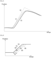
- FIG. 3 illustrates the actual trajectory 82 of a variable valve timing system, in particular intake valves, subject to a position setpoint 80, and an anticipated trajectory 81 used to estimate the quantity of air admitted into the combustion chamber and the amount of fuel when the fuel injectors open.
- FIG. 4 illustrates a construction diagram of an anticipated trajectory of a position of a variable valve timing system.
- the dead time 87 between the setpoint 83 and the real position 86 is reduced by the anticipation 85 to the reduced dead time 88 which corresponds to the dead time between the setpoint 83 and the anticipated real position 84.
- the response model 63 uses for the anticipated actual position 84 the same position gradient as that of setpoint 83, until the value of setpoint 83 is reached. However, in the case where the position gradient of setpoint 83 is greater than the maximum displacement speed of the variable valve timing system, the gradient of the anticipated actual position 84 is limited to this maximum speed.
- the reduced dead time 88 can also be applied during changes of direction of the variable valve timing system (that is to say: passage from a rotation from clockwise to counter-clockwise or vice versa) without there was no stabilization of the position.
- the computer 70 estimates the necessary air flow from the results obtained in step 64 of predictive calculation of the position of the variable timing system 50 of the intake valves (and possibly also of the variable exhaust valve timing system 52).
- the method 60 continues at step 66 with the calculation of the quantity Q of fuel to be injected into the cylinders 12, for an operation of the engine 10 at richness equal to 1, and by the opening of the fuel injectors by the computer in order to inject the calculated fuel flow.
- the quantity Q of fuel to be injected is calculated from the estimated air flow, and in particular, in the case where the richness setpoint is equal to 1, the fuel flow is calculated in proportion to 1 g of fuel for 14 .7g of air.
Landscapes
- Engineering & Computer Science (AREA)
- Chemical & Material Sciences (AREA)
- Combustion & Propulsion (AREA)
- Mechanical Engineering (AREA)
- General Engineering & Computer Science (AREA)
- Output Control And Ontrol Of Special Type Engine (AREA)
- Electrical Control Of Air Or Fuel Supplied To Internal-Combustion Engine (AREA)
Applications Claiming Priority (1)
| Application Number | Priority Date | Filing Date | Title |
|---|---|---|---|
| FR2201608A FR3132933B1 (fr) | 2022-02-23 | 2022-02-23 | Procédé de contrôle de la richesse du mélange carburé d’un moteur à combustion interne de véhicule automobile |
Publications (2)
| Publication Number | Publication Date |
|---|---|
| EP4234909A1 true EP4234909A1 (de) | 2023-08-30 |
| EP4234909B1 EP4234909B1 (de) | 2026-04-01 |
Family
ID=81581201
Family Applications (1)
| Application Number | Title | Priority Date | Filing Date |
|---|---|---|---|
| EP23156550.8A Active EP4234909B1 (de) | 2022-02-23 | 2023-02-14 | Verfahren zur steuerung des gemischverhältnisses des kraftstoffgemischs einer brennkraftmaschine eines kraftfahrzeugs |
Country Status (2)
| Country | Link |
|---|---|
| EP (1) | EP4234909B1 (de) |
| FR (1) | FR3132933B1 (de) |
Citations (7)
| Publication number | Priority date | Publication date | Assignee | Title |
|---|---|---|---|---|
| KR20070106179A (ko) * | 2006-04-28 | 2007-11-01 | 현대자동차주식회사 | 가변 밸브 타이밍 장치 장착 차량의 연료량 제어방법 |
| US20120042850A1 (en) * | 2010-08-17 | 2012-02-23 | Gm Global Technology Operations, Inc. | Model-based transient fuel injection timing control methodology |
| JP2013167199A (ja) * | 2012-02-15 | 2013-08-29 | Hitachi Automotive Systems Ltd | エンジンの制御装置 |
| WO2020084204A1 (fr) * | 2018-10-24 | 2020-04-30 | Psa Automobiles Sa | Procede de regulation du debit d'air d'une vanne de recirculation des gaz a l'echappement utilisant un modele de rendement volumetrique anticipe |
| WO2021019626A1 (ja) * | 2019-07-26 | 2021-02-04 | 日産自動車株式会社 | 内燃エンジンの制御方法および制御装置 |
| DE102020202892A1 (de) * | 2020-03-06 | 2021-09-09 | Volkswagen Aktiengesellschaft | Verfahren zur Vorsteuerung eines Kraftstoff-Luft-Gemisches für mindestens einen Brennraum einer Verbrennungskraftmaschine |
| CN114033524A (zh) * | 2021-11-09 | 2022-02-11 | 上海汽车集团股份有限公司 | 两阶段可变气门升程控制方法及系统 |
-
2022
- 2022-02-23 FR FR2201608A patent/FR3132933B1/fr active Active
-
2023
- 2023-02-14 EP EP23156550.8A patent/EP4234909B1/de active Active
Patent Citations (7)
| Publication number | Priority date | Publication date | Assignee | Title |
|---|---|---|---|---|
| KR20070106179A (ko) * | 2006-04-28 | 2007-11-01 | 현대자동차주식회사 | 가변 밸브 타이밍 장치 장착 차량의 연료량 제어방법 |
| US20120042850A1 (en) * | 2010-08-17 | 2012-02-23 | Gm Global Technology Operations, Inc. | Model-based transient fuel injection timing control methodology |
| JP2013167199A (ja) * | 2012-02-15 | 2013-08-29 | Hitachi Automotive Systems Ltd | エンジンの制御装置 |
| WO2020084204A1 (fr) * | 2018-10-24 | 2020-04-30 | Psa Automobiles Sa | Procede de regulation du debit d'air d'une vanne de recirculation des gaz a l'echappement utilisant un modele de rendement volumetrique anticipe |
| WO2021019626A1 (ja) * | 2019-07-26 | 2021-02-04 | 日産自動車株式会社 | 内燃エンジンの制御方法および制御装置 |
| DE102020202892A1 (de) * | 2020-03-06 | 2021-09-09 | Volkswagen Aktiengesellschaft | Verfahren zur Vorsteuerung eines Kraftstoff-Luft-Gemisches für mindestens einen Brennraum einer Verbrennungskraftmaschine |
| CN114033524A (zh) * | 2021-11-09 | 2022-02-11 | 上海汽车集团股份有限公司 | 两阶段可变气门升程控制方法及系统 |
Also Published As
| Publication number | Publication date |
|---|---|
| EP4234909B1 (de) | 2026-04-01 |
| FR3132933A1 (fr) | 2023-08-25 |
| FR3132933B1 (fr) | 2026-04-24 |
Similar Documents
| Publication | Publication Date | Title |
|---|---|---|
| EP1815118B1 (de) | Vorrichtung und verfahren zur bestimmung der von einem dieselmotor eines kraftfahrzeuges ausgestossenen nox-menge und diagnose- sowie motorverwaltungssystem mit einer derartigen vorrichtung | |
| EP2211043A1 (de) | Verfahren zur Steuerung der in einem Zylinder eines Benzinmotors mit variablem Ventiltrieb eingeschlossenen Gasmasse | |
| EP0954689A1 (de) | Steuervorrichtung für eine brennkraftmaschine mit gesteuerter zündung und direkter einspritzung | |
| EP4234909B1 (de) | Verfahren zur steuerung des gemischverhältnisses des kraftstoffgemischs einer brennkraftmaschine eines kraftfahrzeugs | |
| EP2430298A1 (de) | Schätzung der stickoxidkonzentration in einem verbrennungsmotor | |
| FR2872220A1 (fr) | Procede de commande d'un debit de gaz d'echappement recircules dans un moteur de vehicule | |
| FR2923544A1 (fr) | Moteur a combustion interne du type diesel suralimente et procede de commande du debit d'air et du taux de gaz d'echappement recycle dans un tel moteur | |
| EP4163484A1 (de) | Verfahren zur steuerung des von einem verbrennungsmotor eines kraftfahrzeugs abgegebenen drehmoments mit einem asymmetrischen zyklus | |
| JP3598724B2 (ja) | 内燃機関の制御装置 | |
| FR3132546A1 (fr) | Procédé de contrôle du débit dans un conduit de recirculation partielle de gaz d’échappement à l’admission d’un moteur et dispositif associé | |
| EP3805544A1 (de) | Steuerung eines aufgeladenen motors mit fremdzündung und niederdruckabgasrückführung | |
| WO2013030471A1 (fr) | Système et procédé de commande d'un moteur a combustion interne d'un véhicule automobile avec des circuits de recirculation de gaz d'échappement haute et basse pression en fonctionnement transitoire | |
| EP3004608B1 (de) | Verfahren zur messung des schadstoffausstosses eines verbrennungsmotors und verfahren zur steuerung des motors | |
| EP2655838A1 (de) | System und verfahren zur steuerung eines verbrennungsmotors für ein kraftfahrzeug auf dem transportweg | |
| EP1760295B1 (de) | Regelvorrichtung für eine Diesel-Brennkraftmaschine mit Abgasrückführung | |
| EP4222363B1 (de) | Verfahren zur bestimmung der masse von aspiriertem gas in einem zylinder unter berücksichtigung realer verwendungsbedingungen | |
| EP2256322A1 (de) | Einfluss der NOx Regelung auf die Motorgeräuschregelung in einer Brennkraftmaschine | |
| EP1445458A1 (de) | Verfahren zur Abschätzung des Luft/Krafstoffverhältnisses eines Motors, dieses verwendende Motorregelung, und entsprechende Vorrichtung | |
| FR2871195A1 (fr) | Procede et dispositif de gestion d'un moteur a combustion interne | |
| FR2878575A1 (fr) | Procede de regulation d'un systeme d'admission d'un moteur a combustion interne et vehicule automobile pour la mise en oeuvre du procede | |
| FR3152293A1 (fr) | Procédé de réglage de richesse dans un moteur à combustion interne | |
| EP1647692A1 (de) | Ansaugluftsteuerverfahren für eine Brennkraftmaschine und Kraftfahrzeug zur Anwendung dieses Verfahrens | |
| FR3120659A1 (fr) | Calculateur de contrôle moteur pour véhicule automobile | |
| FR2878905A1 (fr) | Procede de gestion d'un moteur a combustion interne | |
| EP4430288A1 (de) | Verfahren zur niederfrequenten schätzung einer rückgeführten abgasflussrate am einlass eines verbrennungsmotors |
Legal Events
| Date | Code | Title | Description |
|---|---|---|---|
| PUAI | Public reference made under article 153(3) epc to a published international application that has entered the european phase |
Free format text: ORIGINAL CODE: 0009012 |
|
| STAA | Information on the status of an ep patent application or granted ep patent |
Free format text: STATUS: THE APPLICATION HAS BEEN PUBLISHED |
|
| AK | Designated contracting states |
Kind code of ref document: A1 Designated state(s): AL AT BE BG CH CY CZ DE DK EE ES FI FR GB GR HR HU IE IS IT LI LT LU LV MC ME MK MT NL NO PL PT RO RS SE SI SK SM TR |
|
| STAA | Information on the status of an ep patent application or granted ep patent |
Free format text: STATUS: REQUEST FOR EXAMINATION WAS MADE |
|
| 17P | Request for examination filed |
Effective date: 20240214 |
|
| RBV | Designated contracting states (corrected) |
Designated state(s): AL AT BE BG CH CY CZ DE DK EE ES FI FR GB GR HR HU IE IS IT LI LT LU LV MC ME MK MT NL NO PL PT RO RS SE SI SK SM TR |
|
| GRAP | Despatch of communication of intention to grant a patent |
Free format text: ORIGINAL CODE: EPIDOSNIGR1 |
|
| STAA | Information on the status of an ep patent application or granted ep patent |
Free format text: STATUS: GRANT OF PATENT IS INTENDED |
|
| RIC1 | Information provided on ipc code assigned before grant |
Ipc: F02D 13/02 20060101AFI20250915BHEP Ipc: F02D 41/18 20060101ALI20250915BHEP Ipc: F02D 41/00 20060101ALI20250915BHEP Ipc: F02D 41/14 20060101ALI20250915BHEP Ipc: F01L 1/34 20060101ALI20250915BHEP |
|
| INTG | Intention to grant announced |
Effective date: 20250929 |
|
| GRAS | Grant fee paid |
Free format text: ORIGINAL CODE: EPIDOSNIGR3 |
|
| GRAA | (expected) grant |
Free format text: ORIGINAL CODE: 0009210 |
|
| STAA | Information on the status of an ep patent application or granted ep patent |
Free format text: STATUS: THE PATENT HAS BEEN GRANTED |
|
| AK | Designated contracting states |
Kind code of ref document: B1 Designated state(s): AL AT BE BG CH CY CZ DE DK EE ES FI FR GB GR HR HU IE IS IT LI LT LU LV MC ME MK MT NL NO PL PT RO RS SE SI SK SM TR |
|
| REG | Reference to a national code |
Ref country code: CH Ref legal event code: F10 Free format text: ST27 STATUS EVENT CODE: U-0-0-F10-F00 (AS PROVIDED BY THE NATIONAL OFFICE) Effective date: 20260401 Ref country code: GB Ref legal event code: FG4D Free format text: NOT ENGLISH |
|
| RAP2 | Party data changed (patent owner data changed or rights of a patent transferred) |
Owner name: HORSE POWERTRAIN SOLUTIONS, S.L.U. |
|
| REG | Reference to a national code |
Ref country code: DE Ref legal event code: R096 Ref document number: 602023014272 Country of ref document: DE |
|
| REG | Reference to a national code |
Ref country code: IE Ref legal event code: FG4D Free format text: LANGUAGE OF EP DOCUMENT: FRENCH |
|
| REG | Reference to a national code |
Ref country code: CH Ref legal event code: Q17 Free format text: ST27 STATUS EVENT CODE: U-0-0-Q10-Q17 (AS PROVIDED BY THE NATIONAL OFFICE) Effective date: 20260430 |