EP4235091A2 - Oberflächenveredelungsstift - Google Patents
Oberflächenveredelungsstift Download PDFInfo
- Publication number
- EP4235091A2 EP4235091A2 EP23176856.5A EP23176856A EP4235091A2 EP 4235091 A2 EP4235091 A2 EP 4235091A2 EP 23176856 A EP23176856 A EP 23176856A EP 4235091 A2 EP4235091 A2 EP 4235091A2
- Authority
- EP
- European Patent Office
- Prior art keywords
- stylus
- contact element
- shaft
- surface finish
- longitudinal axis
- Prior art date
- Legal status (The legal status is an assumption and is not a legal conclusion. Google has not performed a legal analysis and makes no representation as to the accuracy of the status listed.)
- Pending
Links
Images

Classifications
-
- B—PERFORMING OPERATIONS; TRANSPORTING
- B23—MACHINE TOOLS; METAL-WORKING NOT OTHERWISE PROVIDED FOR
- B23Q—DETAILS, COMPONENTS, OR ACCESSORIES FOR MACHINE TOOLS, e.g. ARRANGEMENTS FOR COPYING OR CONTROLLING; MACHINE TOOLS IN GENERAL CHARACTERISED BY THE CONSTRUCTION OF PARTICULAR DETAILS OR COMPONENTS; COMBINATIONS OR ASSOCIATIONS OF METAL-WORKING MACHINES, NOT DIRECTED TO A PARTICULAR RESULT
- B23Q17/00—Arrangements for observing, indicating or measuring on machine tools
- B23Q17/20—Arrangements for observing, indicating or measuring on machine tools for indicating or measuring workpiece characteristics, e.g. contour, dimension, hardness
-
- G—PHYSICS
- G01—MEASURING; TESTING
- G01B—MEASURING LENGTH, THICKNESS OR SIMILAR LINEAR DIMENSIONS; MEASURING ANGLES; MEASURING AREAS; MEASURING IRREGULARITIES OF SURFACES OR CONTOURS
- G01B21/00—Measuring arrangements or details thereof, where the measuring technique is not covered by the other groups of this subclass, unspecified or not relevant
- G01B21/02—Measuring arrangements or details thereof, where the measuring technique is not covered by the other groups of this subclass, unspecified or not relevant for measuring length, width, or thickness
- G01B21/04—Measuring arrangements or details thereof, where the measuring technique is not covered by the other groups of this subclass, unspecified or not relevant for measuring length, width, or thickness by measuring coordinates of points
-
- G—PHYSICS
- G01—MEASURING; TESTING
- G01B—MEASURING LENGTH, THICKNESS OR SIMILAR LINEAR DIMENSIONS; MEASURING ANGLES; MEASURING AREAS; MEASURING IRREGULARITIES OF SURFACES OR CONTOURS
- G01B5/00—Measuring arrangements characterised by the use of mechanical techniques
- G01B5/28—Measuring arrangements characterised by the use of mechanical techniques for measuring roughness or irregularity of surfaces
-
- G—PHYSICS
- G01—MEASURING; TESTING
- G01B—MEASURING LENGTH, THICKNESS OR SIMILAR LINEAR DIMENSIONS; MEASURING ANGLES; MEASURING AREAS; MEASURING IRREGULARITIES OF SURFACES OR CONTOURS
- G01B7/00—Measuring arrangements characterised by the use of electric or magnetic techniques
- G01B7/34—Measuring arrangements characterised by the use of electric or magnetic techniques for measuring roughness or irregularity of surfaces
Definitions
- the present invention relates to surface finish styli and in particular to surface finish styli for use with multi-directional, machine tool scanning probes for measuring the surface roughness or surface waviness of machined parts.
- a typical profilometer includes an elongate shaft having a workpiece-contacting tip that extends perpendicularly from the distal end of the shaft.
- the tip is placed in contact with the surface to be measured and then pushed or pulled along that surface thereby following any fine features (e.g., valleys and peaks) of the surface.
- a sensor monitors vertical deflection of the tip as it is moved across the horizontal surface thereby providing a measure of surface roughness. It should be noted that profilometers are unidirectional devices because they are arranged to only measure the vertical component of stylus tip deflection (i.e., deflection of the tip in the direction perpendicular to the surface along which the tip is moved).
- a coordinate measuring machine having a multi-directional probe traditionally used to measure the form of objects is described in US5778551 . It is also described in US5778551 how a surface finish stylus may be attached to such a multi-directional probe via a rotary joint. This arrangement enables, by appropriate rotation of the surface finish stylus relative to the scanning probe using the rotary joint, the acquisition of surface finish measurements from differently oriented surfaces.
- US5778551 thus describes a dedicated CMM (i.e. not a machine tool) adapted to measure surface finish in a similar manner to a profilometer. Although such a CMM is more flexible than a profilometer, it is also considerably more expensive than a profilometer and does little to improve the speed of the production process.
- a surface finish stylus comprising an elongate shaft carrying a rotationally symmetrical disk that protrudes orthogonally from the shaft.
- the region of largest diameter of the disk acts as a contact sensing surface and the rotational symmetry of the disk allows the surface finish of any surface aligned parallel to the longitudinal axis of the elongate shaft to be measured when the shaft is moved relative to that surface along its longitudinal axis. In this manner, the surface finish of different regions on the internal surface of a bore can be measured without having to re-orientate the scanning probe.
- US2016/0231108 may be suitable for a limited number of "on-machine" surface finish measurements (e.g. measurements of the internal surfaces of a bore), but there still remain many different surface orientations on a typical machined part that simply can't be measured using such apparatus.
- WO90/00717 describes a probe for measuring the form of objects.
- a spherical stylus tip is replaced with a conical stylus tip to improve the performance of the probe when measuring the shape of smoothly-curved surfaces, such as aerofoils.
- the present invention thus relates to a surface finish stylus for a multi-directional scanning probe.
- a multi-directional probe can measure the deflection of an attached stylus in multiple directions rather than the single direction of deflection that can be sensed by the unidirectional measurement sensor of a prior art profilometer.
- the stylus of the present invention also has an elongate stylus shaft having a longitudinal axis with a contact element protruding from the elongate shaft.
- the contact element is arranged for contacting a surface to be measured and enables surface finish (e.g., surface roughness and/or surface waviness etc) to be measured as it is moved along the surface.
- the contact element follows the surface along which it is moved and motion of the contact element in the direction perpendicular to the surface can then be measured by a multi-directional probe to which the stylus shaft is attached.
- the stylus shaft is positioned so that the spike or disk that protrudes perpendicularly from the shaft contacts the surface to be measured.
- the stylus is positioned relative to the surface so that the protruding spike or disk is aligned with the surface normal.
- the stylus shaft is then moved parallel to the plane of the surface to maintain alignment of the spike or disk with the surface normal whilst it is dragged over the surface. Deflection of the spike or disk in the surface normal direction is measured to establish how the surface varies along the surface.
- Prior art surface finish measurements are thus collected whilst the stylus shaft is moved relative to the surface along a direction that is parallel to the longitudinal axis of the stylus shaft.
- This restriction on relative orientation and motion means that the measurement device and/or object need to be re-orientated to measure surfaces of an object in different planes (e.g., horizonal and vertical surfaces) which is time consuming or even not possible when using certain models of machine tool.
- the present invention enables measurement of surface finish during motion of the stylus shaft relative to a surface along a measurement direction that is non-parallel to the longitudinal axis.
- the contact element allow measurement of surface finish unhindered by the constraint of prior art systems of having to ensure the stylus shaft is moved relative to a surface along a direction that is parallel to the longitudinal axis of the stylus shaft.
- the contact element of the stylus of the present invention protrudes from the shaft at an oblique angle to the longitudinal axis. This contact element configuration enables the stylus to be moved to sense the surface finish of multiple surfaces of an object having different orientations (e.g., horizonal and vertical surfaces) without having to re-orientate the probe relative to the object.
- the contact element is orientated at an oblique angle to the longitudinal axis.
- the contact element does not extend perpendicularly from the shaft as per prior art styli, but instead protrudes at a non-perpendicular or oblique angle to the stylus shaft.
- the stylus shaft can thus be tilted relative to a surface and moved in a direction that is non-parallel to its longitudinal axis to maintain alignment of the contact element with the surface normal of a surface as it is moved along that surface.
- a plurality of contact elements may be provided. These may extend from the shaft at angles which allow different orientation surfaces to be measured without having to re-orientate the probe relative to the object.
- the contact element comprises a hollow conical element.
- the conical element has a peripheral edge that protrudes from the elongate stylus shaft at an oblique angle to the longitudinal axis.
- the peripheral edge preferably forms a base of the cone and the apex of the cone may be coincident with the longitudinal axis of the stylus shaft.
- the peripheral edge is preferably arranged to contact the surface to be measured; for example, the peripheral edge of the hollow cone may be rounded and have a suitable effective radius for the surface finish measurement.
- the conical element may comprise a complete hollow cone (i.e., with a peripheral edge around the full 360° of the circumference) or a partial hollow cone (i.e. with a peripheral edge around only part of the stylus shaft circumference).
- the peripherical edge is brought into contact with the surface of an object with the stylus suitably orientated so that the direction along which the conical element extends from the stylus shaft is locally aligned with the surface normal.
- the stylus can then be translated to move the conical element along the surface whilst maintaining local alignment with the surface normal.
- Surface finish information can be determined from motion of the contact element in the direction perpendicular to the surface.
- the oblique angle is approximately 45°.
- the peripheral edge of the conical element may thus protrude from the stylus shaft at an oblique angle of 45°.
- Such a stylus orientated at 45° to the vertical can be used to measure the surface roughness of both a horizontal and a vertical surface; i.e. diametrically opposed portions of the peripheral edge can be aligned to the surface normal directions of both vertical and horizontal surfaces.
- the stylus can then be moved (pushed or pulled) along vertical and horizontal surfaces of an object by translational motion alone (i.e. there is no need to re-orientate the object relative to the stylus).
- a stylus that has a plurality of contact elements.
- the plurality of contact elements preferably have a plurality of different orientations relative to the stylus shaft.
- multiple contact elements may protrude from the shaft in different directions and/or be aligned at different angles to the shaft.
- one contact element may protrude from the distal end of the stylus shaft along the longitudinal axis and other contact elements may protrude from the side of the shaft.
- the surface finish of surfaces at different orientations relative to the stylus shaft may then be measured using different contact elements. For example, if the stylus was held vertically a horizontal surface may be measured using a contact element protrude from the distal end of the stylus shaft whilst vertical surfaces may be measured using the other contact elements.
- the following description refers to the use of a single contact element in accordance with the first aspect of the invention, and also the provision of a plurality of contact elements in relation to other examples that are described herein.
- the element may be integrally formed with the stylus shaft.
- the contact element may be attached (permanently or releasably) to the stylus shaft.
- the stylus shaft comprises one or more clamps for retaining the contact element. In this manner, one or more contact elements may be clamped to stylus shaft.
- the contact element comprise a metallic disk.
- the metallic disk may be shaped. This shaping of the disk may be done by bending the metallic disk.
- the metallic disk may be shaped to provide the desired arrangement of contact elements (e.g., it may be bent to provide the one or more contact elements or to form a hollow cone).
- the shaping/bending of the disk may also be used to help clamp the disk in a fixed location relative to the stylus shaft.
- the metallic disk may comprise regions of weakness (e.g., thinner regions) that promote bending to the desired shape. Any such bending of a metallic disk may be achieved as it is clamped to the stylus shaft (e.g., using the clamps described above).
- the metallic disk may also comprise a plurality of slits formed therein that enable a plurality of regions of the disk to be bent to form contact elements that protrude from the plane of the metallic disk.
- a single piece of material e.g., a single metallic disk
- a plurality of separate contact elements may be attached to the stylus shaft.
- the one or more contact elements may be formed from any suitable material.
- a ceramic or glass material may be used.
- the one or more contact elements may be formed from a metal.
- the material forming the one or more contact elements preferably has a low stiffness (to minimise damage to the surface being measured).
- the Young's modulus (E) of the one or more contact elements is less than 250 GPa. More preferably, the Young's modulus of the one or more contact elements is less than 150 GPa. More preferably, the Young's modulus of the one or more contact elements is less than 100 GPa. More preferably, the Young's modulus of the one or more contact elements is less than 50 GPa.
- the material is also mechanically hard (i.e. to reduce wear).
- the material forming the one or more contact elements thus preferably has a high hardness.
- the hardness (H) of the one or more contact elements is greater than 1 GPa.
- the hardness (H) of the one or more contact elements is greater than 2 GPa.
- the hardness (H) of the one or more contact elements is greater than 5 GPa.
- the Young's modulus (E) and hardness (H) properties of the one or more contact elements are each important in their own right, but it is also possible to use the ratio of stiffness to hardness (the "E/H" ratio) when selecting a suitable material for the contact elements.
- the E/H ratio is as low as possible.
- the E/H ratio is preferably less than 50. More preferably, the E/H ratio is less than 20. More preferably, the E/H ratio is 15 or less. More preferably, the E/H ratio is less than 10.
- the one or more contact elements may comprise any suitable material (e.g. having the properties outlined above).
- the contact element may be formed from multiple materials.
- the contact element comprises a single material.
- the contact element(s) comprise metal; for example, a metallic disk or metallic sheet of material may form the contact element.
- the contact element may comprise steel.
- the one or more contact elements may be configured to measure any aspect of surface finish. It should be noted that the term surface finish refers to finer details of the surface than the form of the surface that is measured by standard scanning probes.
- the one or more contact elements may be configured to measure surface waviness.
- the one or more contact elements may be configured to measure surface roughness. Surface waviness and surface roughness are examples of surface finish.
- the one or more contact elements are preferably dimensioned to measure the required aspect of surface finish.
- the distal end (or tip) of the one or more contact elements may have an effective radius of less than 300 ⁇ m.
- the effective radius is the radius or dimension of the contact element in the direction parallel to the direction the contact element is moved over the surface (e.g. the thickness of the edge of a contact element disk).
- the one or more contact elements may have an effective radius of less than 200 ⁇ m.
- the one or more contact elements have an effective radius of less than 100 ⁇ m.
- the one or more contact elements have an effective radius of less than 50 ⁇ m.
- the measured variation in surface texture may be used to generate an "Ra" surface roughness value.
- the stylus is preferably non-skidded (i.e. it preferably does not comprise a skid and only the contact element engages the surface being measured).
- the stylus shaft is preferably directly attachable to the stylus holder of a scanning probe.
- the stylus shaft is also preferably rigid.
- the stylus shaft does not include any rotary (knuckle) joints or the like for altering the orientation of the contact elements relative to the stylus holder of the scanning probe to which it is attached. In this manner, the location and orientation of the contact elements is invariable relative to the stylus holder of the scanning probe to which it is attached.
- the present invention also extends to a multidirectional scanning probe that includes the above-described surface finish stylus of the first aspect of the invention.
- the multi-directional scanning probe may then be used for acquiring surface finish measurements.
- the multi-directional scanning probe preferably comprises a probe body and a stylus holder moveably attached to the probe body.
- the stylus may be deflectable relative to the housing of the scanning probe in any one of two mutually perpendicular directions or in any of three mutually perpendicular directions.
- At least one deflection sensor may be provided for measuring deflection of the stylus holder relative to the probe body.
- a surface finish stylus as described above may be attached to the stylus holder (e.g. via a standard screw-thread attachment).
- the scanning probe comprises a machine tool scanning probe (i.e. a scanning probe suitable for use in a machine tool environment).
- the scanning probe may include a deflection sensor that can only measure the magnitude (not direction) of stylus deflection; i.e. the scanning probe may comprise a multidirectional, single output scanning probe that generates probe data describing only the magnitude of stylus deflection.
- the scanning probe may comprise a TC76-Digilog or a TC64-Digilog scanning probe as manufactured by Blum Novotest GmbH, Germany or a model G25 probe sold by Marposs, Italy.
- the scanning probe may comprise sensors that can measure both the magnitude and direction of any stylus deflection.
- the analogue scanning probe may generate three output signals that relate to the deflection of the stylus tip in three mutually orthogonal directions.
- the SPRINT (OSP-60) probing system manufactured by Renishaw plc, Wotton-Under-Edge, UK is an example of such a scanning probe.
- a surface finish stylus for a multi-directional scanning probe comprising; an elongate stylus shaft having a longitudinal axis, and one or more contact elements protruding from the elongate shaft for contacting a surface to be measured, characterised in that the one or more contact elements are configured to enable measurement of surface finish during motion of the stylus shaft relative to a surface along a measurement direction that is non-parallel to the longitudinal axis.
- the stylus may include any of the features described above for the first aspect of the invention.
- Also described herein is a method for measuring the surface finish of an object using a multi-directional scanning probe comprising a surface finish stylus, the surface finish stylus comprising an elongate stylus shaft having a longitudinal axis and one or more contact elements protruding from the elongate shaft for contacting a surface to be measured, the method being characterised by the step of measuring surface finish by moving the stylus shaft relative to a surface along a measurement direction that is non-parallel to the longitudinal axis.
- the step of measuring surface finish comprises orientating the surface finish stylus relative to the surface so as to maintain alignment of the contact element with the local surface normal whilst the stylus shaft is moved relative to the surface along the measurement direction. In this manner, stylus deflections along the surface normal direction are measured.
- the method may also include any of the features, or ways to use, the stylus that are described above.
- a surface finish stylus for a multi-directional scanning probe that comprises an elongate shaft having a longitudinal axis and a plurality of contact elements extending from the elongate shaft.
- the plurality of contact elements preferably have a plurality of different orientations relative to the stylus shaft.
- the plurality of contact elements comprise a first contact element protruding from the distal end of the elongate shaft along the longitudinal axis.
- the plurality of contact elements comprise at least one contact element protruding radially or obliquely from the elongate shaft. Further contact elements may be provided as required.
- the stylus may also include any of the features of the styli described above.
- a surface finish stylus for a multi-directional scanning probe comprising an elongate shaft having a longitudinal axis and one or more contact elements extending from the elongate shaft at an oblique angle relative to the longitudinal axis.
- the one or more contact elements comprise a hollow conical element.
- the conical element may protrude at an oblique angle of 45° to the longitudinal axis.
- the stylus may also include any of the features of the styli described above.
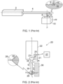
- the profilometer comprises a housing 2 from which extends an elongate shaft 4 having a longitudinal axis L.
- a contact element 6 extends perpendicularly from the shaft 4 along the direction P.
- the housing 2 includes a unidirectional transducer (not shown) that measures any deflection of the shaft 4 caused by motion of the contact element 6 back and forth along the direction P.
- the contact element 6 is brought into contact with the surface of an object 10.
- the contact element 6 is then moved relative to the object 10 in a direction M that is parallel to the longitudinal axis L.
- This relative motion between the object 10 and profilometer may be imparted by moving the profilometer (e.g. by linearly retracting/extending the shaft 4), the object 10, or both the object and the profilometer.
- the result of the relative motion is to cause the contact element 6 to move (i.e. to be pushed or pulled) along a path 12 on the surface of the object 10.
- the contact element 6 also moves up and down to follow the surface; this can be seen in the inset to figure 1 that provides an expanded view of the tip of the contact element 6 and the object's surface.
- the unidirectional transducer within the housing 2 outputs a deflection signal that is related to the vertical deflection of the contact element 6 (i.e. deflection along the direction P). Analysis of the variations in the deflection signal as the path 12 is traversed provides a measure of surface finish of that region of the object. For example, an average surface roughness or R a value may be calculated.
- the scanning probe of US2016/0231108 is a multi-directional scanning probe that can be mounted to the spindle of a machine tool to allow "on-machine" measurement of workpieces.
- the scanning probe 20 comprises a probe body 22 and a stylus holder 21 for retaining a stylus.
- the stylus holder 21 is attached to the probe body 22 by a deflection mechanism (not shown) and a transducer 23 is also provided within the probe body 22 for measuring the magnitude of deflection of the stylus holder 21 (i.e. caused by deflection of an attached stylus) relative to the probe body 22.
- Deflection measurements taken by the transducer 23 are passed by a transmitter unit 25 to a probe interface 27.
- the probe body 22 is also attachable to the spindle of a machine tool via a tool shank (not shown). The probe 20 can thus be moved around the working volume of the machine tool and in particular the probe stylus can be brought into contact with the surface of an object to be measured.
- a scanning probe 20 of this type is traditionally used with a stylus that enables the form of an object to be measured; e.g. such a stylus may comprise a ruby sphere of several millimetres diameter that is attached to the distal end of an elongate shaft.
- a surface roughness stylus 24 is instead attached to the probe 20.
- the surface roughness stylus 24 comprises an elongate shaft 30 and a contact element 28 that extends perpendicularly P from the longitudinal axis L of the shaft 30.
- the contact element 28 has the form of a double-truncated cone with a rounded peripheral edge 26 (shown in the inset to figure 2 ) around its circumference.
- the perpendicular direction P along which the contact element 28 protrudes from the shaft 30 is aligned to be parallel with the surface normal N of a surface to be measured.
- Figure 2 shows a suitable vertical surface 34 of an object 36 in dashed outline.
- the peripheral edge 26 of the contact element 28 is brought into contact with the vertical surface 34 and the probe 20 is then moved vertically upwards in the direction M.
- the probe 20 is moved vertically along a direction M that is both parallel to longitudinal axis L of the stylus shaft 30 and also parallel to the plane of the surface 34.
- the transducer 23 of the scanning probe 20 measures the magnitude of stylus deflection as it is dragged along the surface 34 and these measured deflection values are used to ascertain surface roughness.
- the scanning probe 20 must be moved in a direction M parallel to the longitudinal axis L of the stylus shaft 30 and also parallel to the plane of the surface (e.g. surface 34).
- the plane of the surface e.g. surface 34.
- surface normal N of the surface being measured remains parallel to the perpendicular direction P along which the contact element 28 protrudes from the shaft 30 whilst the path is traversed.
- surface roughness may be measured at any circumferential position within a vertical bore by moving the probe vertically up or down. It is, however, not possible to measure surfaces in a plane angled relative to the longitudinal axis L of the stylus shaft (e.g.
- the scanning probe 20 would have to be re-orientated by 90° relative to an object to measure both a vertical surface and a horizontal surface. Such reorientation is simply not possible on certain models of machine tool and, even if it is possible, can lead to delays in the measurement process thereby increasing production costs.
- the styli described below allow the measurement of the surface roughness along surfaces orientated in a plane that is not parallel to the longitudinal axis of the shaft from which the contact elements used to measure surface finish protrude.
- Styli are also described that allow the measurement of differently orientated surfaces without having to re-orientate the probe or stylus relative to the object.
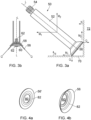
- FIGS 3a and 3b illustrate a surface finish stylus 50 of the present invention.
- the stylus 50 comprises an elongate stylus shaft 52 having a longitudinal axis L.
- the proximal end of the stylus shaft 52 includes a screw-thread attachment member 54 that enables the stylus to be attached to the stylus holder of a multi-directional scanning probe (not shown).
- the distal end of the stylus shaft 52 comprises a contact element in the form of a hollow, conically shaped metallic disk 56.
- the metallic disk 56 is held in a truncated conical recess 58 by a wedge-shaped retaining member 60 that is attached to the stylus shaft by a bolt 62.
- the metallic disk 56 is thus a skirt-like contact element that extends around the circumference of the stylus shaft 52 and protrudes along a direction Q that is angled at 45° relative to the longitudinal axis L.
- the surface finish stylus 50 can be used to measure the surface finish of multiple surfaces having different orientations without having to re-orientate the scanning probe.
- the surface finish stylus 50 is inclined at an angle of 45° to the horizontal (and vertical).
- the surface finish stylus 50 may then be moved in the direction M1 in order to measure the surface finish of a horizontal surface 70; i.e. the contact element 56 is pulled along the horizontal surface 70 by horizonal motion M1 whilst the scanning probe retaining the stylus 50 measures stylus deflection.
- the surface finish stylus 50 may then be moved in the direction M2 in order to measure the surface finish of a vertical surface 72; i.e.
- the protruding contact element 56 maintains a perpendicular orientation to the surface normal N (i.e. the direction Q along which the contact element protrudes from the elongate shaft is kept aligned to the local surface normal N as the stylus is moved along directions M1 and M2).
- the surface finish stylus 50 is not constrained by the limitation that the direction of stylus motion must be along the longitudinal axis of the stylus shaft. This enables surfaces having different orientations to be measured without having to re-orientate the scanning probe relative to the object thereby increasing measurement flexibility and reducing measurement time.
- a flat metallic disk 56' is provided.
- the disk 56' includes a central aperture 80 and an annular region 82 of material that is thinner than the rest of the disk.
- the wedge-shaped retaining member 60 is located on the bolt 62 to engage the flat metallic disk 56' already placed over the threaded bolt; the diameter of the central aperture 80 being slightly larger than the diameter of the bolt thread to provide clearance.
- the bolt 62 is then screwed into the stylus shaft thereby forcing the flat metallic disk 56'into engagement with the truncated conical recess 58.
- the flat metallic disk 56' is thus sandwiched between the wedge-shaped retaining member 60 and the truncated conical recess 58 and tightening the bolt 62 acts to deform the flat metallic disk 56' to provide the conically shaped metallic disk 56 shown in figure 4b and in figure 3b .
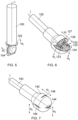
- Figure 5 shows an alternative surface finish stylus.
- An elongate stylus shaft 100 having a longitudinal axis L retains a first contact element 102 and a second contact element 104.
- the first contact element 102 is a disk that extends perpendicularly from the stylus shaft 100 that can sense surface roughness of surfaces aligned with the longitudinal axis L when moved in the direction M1.
- the second contact element 104 is also a disk but is located below and orientated perpendicularly to the first contact element 102.
- the second contact element 104 is located to lie on the longitudinal axis and can measure surface roughness when moved relative to a surface along the direction M2.
- the direction M2 is perpendicular to the direction M1.
- Figure 6 shows an alternative surface finish stylus.
- An elongate stylus shaft 120 having a longitudinal axis L is again provided.
- a slotted metallic disk 122 is attached to the distal end of the shaft 120.
- a first segment 124 of the metallic disk is attached by two screws 123 to a flat support surface that lies in a plane parallel to the longitudinal axis L.
- the first segment 124 provides a contact element that can be used to measure the surface roughness of vertical or horizontal surfaces by movement along the direction M2.
- a second segment 126 of the disk is bent to extend perpendicularly from the longitudinal axis L and held by a screw 127 against a flat support surface that is perpendicular to the longitudinal axis L.
- the second segment 126 forms a contact element for measuring roughness of surfaces aligned with the longitudinal axis L when moved in the direction M1.
- Figure 7 shows an alternative surface finish stylus.
- An elongate stylus shaft 140 having a longitudinal axis L comprises an ovoid shell 142 at its distal end.
- a first contact element 144, a second contact element 146 and a third contact element 148 protrude through apertures in the shell 142.
- the first contact element 144 protrudes from the bottom of the shell 142 along the longitudinal axis.
- the first contact element 144 can thus be used to measure surface roughness of surfaces perpendicular to the stylus. For example, if the longitudinal axis L is aligned to the vertical the first contact element 144 can be moved along a horizontal surface in the direction M3.
- the second contact element 146 extends from the shaft and is orientated to measure surface roughness in the direction M2.
- the second contact element 146 can measure surface roughness along a horizonal contour on a vertical surface.
- the third contact element 148 forms a contact element for measuring roughness of surfaces aligned with the longitudinal axis L when moved in the direction M1.
- a surface finish stylus with additional contact elements or an alternative arrangement of contact elements.
- pairs of contact elements could be provided on opposite sides of the ovoid shell 142.
- FIG. 8a shows a metallic sheet cut to form a disk 160 which includes cutouts that allow selected sections of the disk to be folded.
- Figure 8b shows how the regions 162 and 164 can be folded upwards to provide contact elements for sensing surface finish in the direction M2.
- the region 166 can be folded downwards to form a contact element for sensing surface finish in the direction M3.
- the edge region 168 can provide (without being folded) a contact element for measuring roughness of surfaces aligned with the longitudinal axis L when moved in the direction M1.
- the folder disk of figure 8b may be housed in a shell so that the contact elements protrude through the shell, in a similar manner to that shown in figure 7 .
- Figure 9 illustrates a further surface finish stylus 190 having a elongate stylus shaft 192 with a longitudinal axis L.
- a carrier 194 attached to the shaft 192 holds a first contact element 196 and a second contact element 198.
- the illustrated contact elements 196 and 198 are single bevel edge surface finish styli, as sold by the Mitutoyo Corporation, Kanagawa, Japan.
- the first contact element 196 is orientated to measure surface finish when the stylus is moved in the direction M1 that is parallel to the longitudinal axis L; e.g. to measure surface finish up or down a vertical surface.
- the second contact element 198 is orientated to measure surface finish when the stylus is moved in the direction M2; e.g. to measure surface finish along a horizontal contour of a vertical surface.
Landscapes
- Physics & Mathematics (AREA)
- General Physics & Mathematics (AREA)
- Engineering & Computer Science (AREA)
- Mechanical Engineering (AREA)
- A Measuring Device Byusing Mechanical Method (AREA)
Applications Claiming Priority (3)
| Application Number | Priority Date | Filing Date | Title |
|---|---|---|---|
| GBGB1806828.8A GB201806828D0 (en) | 2018-04-26 | 2018-04-26 | Surface finish stylus |
| PCT/GB2019/051130 WO2019207293A1 (en) | 2018-04-26 | 2019-04-23 | Surface finish stylus |
| EP19727713.0A EP3784979B1 (de) | 2018-04-26 | 2019-04-23 | Oberflächenveredelungsstift |
Related Parent Applications (2)
| Application Number | Title | Priority Date | Filing Date |
|---|---|---|---|
| EP19727713.0A Division EP3784979B1 (de) | 2018-04-26 | 2019-04-23 | Oberflächenveredelungsstift |
| EP19727713.0A Division-Into EP3784979B1 (de) | 2018-04-26 | 2019-04-23 | Oberflächenveredelungsstift |
Publications (2)
| Publication Number | Publication Date |
|---|---|
| EP4235091A2 true EP4235091A2 (de) | 2023-08-30 |
| EP4235091A3 EP4235091A3 (de) | 2023-10-04 |
Family
ID=62495006
Family Applications (2)
| Application Number | Title | Priority Date | Filing Date |
|---|---|---|---|
| EP23176856.5A Pending EP4235091A3 (de) | 2018-04-26 | 2019-04-23 | Oberflächenveredelungsstift |
| EP19727713.0A Active EP3784979B1 (de) | 2018-04-26 | 2019-04-23 | Oberflächenveredelungsstift |
Family Applications After (1)
| Application Number | Title | Priority Date | Filing Date |
|---|---|---|---|
| EP19727713.0A Active EP3784979B1 (de) | 2018-04-26 | 2019-04-23 | Oberflächenveredelungsstift |
Country Status (6)
| Country | Link |
|---|---|
| US (1) | US11326869B2 (de) |
| EP (2) | EP4235091A3 (de) |
| JP (1) | JP7422678B2 (de) |
| CN (2) | CN112292576A (de) |
| GB (1) | GB201806828D0 (de) |
| WO (1) | WO2019207293A1 (de) |
Families Citing this family (4)
| Publication number | Priority date | Publication date | Assignee | Title |
|---|---|---|---|---|
| GB201806830D0 (en) * | 2018-04-26 | 2018-06-13 | Renishaw Plc | Surface finish stylus |
| TWI850251B (zh) * | 2018-09-03 | 2024-08-01 | 義大利商Hsd股份公司 | 工具機、用於工具機的操作裝置、以及收集工具機的操作資料的系統及方法 |
| SE546901C2 (en) * | 2022-12-29 | 2025-03-04 | Sandvik Machining Solutions Ab | Probe with multiple contact portions |
| EP4679030A1 (de) | 2024-07-11 | 2026-01-14 | Renishaw plc | Abtastsonde und verfahren |
Citations (3)
| Publication number | Priority date | Publication date | Assignee | Title |
|---|---|---|---|---|
| WO1990000717A1 (en) | 1988-07-05 | 1990-01-25 | National Research Development Corporation | Probes |
| US5778551A (en) | 1995-03-11 | 1998-07-14 | Carl-Zeiss-Stiftung | Coordinate measuring apparatus having a device for profile measurements and method for making said profile measurements |
| US20160231108A1 (en) | 2013-09-13 | 2016-08-11 | Blum-Novotest Gmbh | Roughness Measuring Instrument for Use in a Machine Tool and Method for Measuring Roughness in a Machine Tool |
Family Cites Families (19)
| Publication number | Priority date | Publication date | Assignee | Title |
|---|---|---|---|---|
| GB1568054A (en) * | 1976-10-01 | 1980-05-21 | Renishaw Electrical Ltd | Contactsensing probe |
| FR2458791A1 (fr) | 1979-06-13 | 1981-01-02 | Seiv Automation | Dispositif de mesure a commande numerique |
| GB2070249A (en) | 1980-02-21 | 1981-09-03 | Rank Organisation Ltd | Contact-sensitive probe |
| DE3417014A1 (de) | 1984-05-09 | 1985-11-21 | Fa. Carl Zeiss, 7920 Heidenheim | Taststifthalter |
| GB8610087D0 (en) | 1986-04-24 | 1986-05-29 | Renishaw Plc | Probe |
| JPS62181354U (de) * | 1986-05-12 | 1987-11-17 | ||
| CH674485A5 (de) | 1988-03-11 | 1990-06-15 | Saphirwerk Ind Prod | |
| US5757496A (en) * | 1997-03-07 | 1998-05-26 | Mitutoyo Corporation | Method of surface roughness measurement using a fiber-optic probe |
| JP3967274B2 (ja) * | 2003-02-27 | 2007-08-29 | 株式会社ミツトヨ | 測定装置 |
| US7368712B2 (en) * | 2005-12-06 | 2008-05-06 | International Business Machines Corporation | Y-shaped carbon nanotubes as AFM probe for analyzing substrates with angled topography |
| CN104040288B (zh) * | 2012-01-04 | 2016-12-14 | 株式会社东京精密 | 轮廓形状表面粗糙度测定装置以及轮廓形状表面粗糙度测定方法 |
| US9726481B2 (en) * | 2012-04-18 | 2017-08-08 | Renishaw Plc | Method of analogue measurement scanning on a machine tool |
| JP6104557B2 (ja) * | 2012-10-18 | 2017-03-29 | 株式会社ミツトヨ | 表面粗さ測定ユニット、三次元測定装置 |
| JP6047045B2 (ja) * | 2013-03-25 | 2016-12-21 | 株式会社ミツトヨ | 輪郭測定機 |
| GB201316329D0 (en) * | 2013-09-13 | 2013-10-30 | Renishaw Plc | A Method of Using a scanning probe |
| US10393505B2 (en) * | 2013-12-06 | 2019-08-27 | Werth Messtechnik Gmbh | Device and method for measuring workpieces |
| EP3317608A4 (de) * | 2014-10-06 | 2019-03-06 | US Synthetic Corporation | Sonden, taster, systeme damit und verfahren zur herstellung |
| JP5846462B1 (ja) | 2014-10-28 | 2016-01-20 | 株式会社東京精密 | 形状測定装置 |
| GB201806830D0 (en) * | 2018-04-26 | 2018-06-13 | Renishaw Plc | Surface finish stylus |
-
2018
- 2018-04-26 GB GBGB1806828.8A patent/GB201806828D0/en not_active Ceased
-
2019
- 2019-04-23 EP EP23176856.5A patent/EP4235091A3/de active Pending
- 2019-04-23 CN CN201980027603.1A patent/CN112292576A/zh active Pending
- 2019-04-23 EP EP19727713.0A patent/EP3784979B1/de active Active
- 2019-04-23 JP JP2020559463A patent/JP7422678B2/ja active Active
- 2019-04-23 CN CN202310568896.2A patent/CN116604402A/zh active Pending
- 2019-04-23 US US17/041,864 patent/US11326869B2/en active Active
- 2019-04-23 WO PCT/GB2019/051130 patent/WO2019207293A1/en not_active Ceased
Patent Citations (3)
| Publication number | Priority date | Publication date | Assignee | Title |
|---|---|---|---|---|
| WO1990000717A1 (en) | 1988-07-05 | 1990-01-25 | National Research Development Corporation | Probes |
| US5778551A (en) | 1995-03-11 | 1998-07-14 | Carl-Zeiss-Stiftung | Coordinate measuring apparatus having a device for profile measurements and method for making said profile measurements |
| US20160231108A1 (en) | 2013-09-13 | 2016-08-11 | Blum-Novotest Gmbh | Roughness Measuring Instrument for Use in a Machine Tool and Method for Measuring Roughness in a Machine Tool |
Also Published As
| Publication number | Publication date |
|---|---|
| EP4235091A3 (de) | 2023-10-04 |
| JP2021522490A (ja) | 2021-08-30 |
| CN112292576A (zh) | 2021-01-29 |
| US11326869B2 (en) | 2022-05-10 |
| GB201806828D0 (en) | 2018-06-13 |
| EP3784979B1 (de) | 2023-07-12 |
| WO2019207293A1 (en) | 2019-10-31 |
| JP7422678B2 (ja) | 2024-01-26 |
| US20210033379A1 (en) | 2021-02-04 |
| CN116604402A (zh) | 2023-08-18 |
| EP3784979A1 (de) | 2021-03-03 |
Similar Documents
| Publication | Publication Date | Title |
|---|---|---|
| EP3784979B1 (de) | Oberflächenveredelungsstift | |
| JP5539865B2 (ja) | 走査ヘッドの較正装置および方法 | |
| JP2988588B2 (ja) | 位置測定装置 | |
| JP5868612B2 (ja) | 測定装置 | |
| JP2016536603A (ja) | 工作機械内で使用するための粗さ測定機器及び工作機械内で粗さ測定する方法 | |
| EP4193119B1 (de) | Messverfahren | |
| CN108700413A (zh) | 用于校准扫描探针的方法和装置 | |
| CN110291360A (zh) | 校准表面感测装置的方法、用于控制计算机的相应校准程序以及相应校准套件 | |
| CN100460814C (zh) | 使用机器测量制品的方法和设备 | |
| EP2050534B1 (de) | Verfahren zum Prüfen einer Rotationsachse mit einer selbstzentrierenden Messvorrichtung | |
| Ali | Probing system characteristics in coordinate metrology | |
| JP4570437B2 (ja) | 表面粗さ/輪郭形状測定装置 | |
| US12018938B2 (en) | Surface finish stylus | |
| Masashi et al. | Evaluation of linear axis motion error of machine tools using an R-test device | |
| JP2009180700A (ja) | 円筒形状測定装置および円筒の表面形状測定方法 | |
| JP3939805B2 (ja) | Nc工作機械用ワーク測定方法 | |
| Tsutsumi et al. | New measuring method of circular movement of NC machine tools: Development of alternative method for standardization | |
| EP4563935A1 (de) | Verfahren zur bestimmung von informationen über eine oder mehrere vertiefungen in einem teil | |
| Cedilnik et al. | Scanning errors identification using touch trigger probe head | |
| Salah | Two dimensional mofel of CMM probing system | |
| JPH0213243B2 (de) | ||
| JP2002071336A (ja) | 角度計と変位計の組み合わせによる回転体の円周形状と運動精度の分離測定方法及び測定装置 | |
| de Castro | Dynamic Accuracy Assessment of Machine Tools and Equipment Using a Laser Interferometer | |
| PL223263B1 (pl) | Urządzenie do pozycjonowania i bezpośredniego pomiaru zużycia narzędzi skrawających maszyn sterowanych numerycznie |
Legal Events
| Date | Code | Title | Description |
|---|---|---|---|
| PUAI | Public reference made under article 153(3) epc to a published international application that has entered the european phase |
Free format text: ORIGINAL CODE: 0009012 |
|
| STAA | Information on the status of an ep patent application or granted ep patent |
Free format text: STATUS: THE APPLICATION HAS BEEN PUBLISHED |
|
| REG | Reference to a national code |
Ref country code: DE Ref legal event code: R079 Free format text: PREVIOUS MAIN CLASS: G01B0005280000 Ipc: G01B0007340000 |
|
| AC | Divisional application: reference to earlier application |
Ref document number: 3784979 Country of ref document: EP Kind code of ref document: P |
|
| AK | Designated contracting states |
Kind code of ref document: A2 Designated state(s): AL AT BE BG CH CY CZ DE DK EE ES FI FR GB GR HR HU IE IS IT LI LT LU LV MC MK MT NL NO PL PT RO RS SE SI SK SM TR |
|
| PUAL | Search report despatched |
Free format text: ORIGINAL CODE: 0009013 |
|
| AK | Designated contracting states |
Kind code of ref document: A3 Designated state(s): AL AT BE BG CH CY CZ DE DK EE ES FI FR GB GR HR HU IE IS IT LI LT LU LV MC MK MT NL NO PL PT RO RS SE SI SK SM TR |
|
| RIC1 | Information provided on ipc code assigned before grant |
Ipc: G01B 5/28 20060101ALI20230829BHEP Ipc: G01B 7/34 20060101AFI20230829BHEP |
|
| STAA | Information on the status of an ep patent application or granted ep patent |
Free format text: STATUS: REQUEST FOR EXAMINATION WAS MADE |
|
| 17P | Request for examination filed |
Effective date: 20240314 |
|
| RBV | Designated contracting states (corrected) |
Designated state(s): AL AT BE BG CH CY CZ DE DK EE ES FI FR GB GR HR HU IE IS IT LI LT LU LV MC MK MT NL NO PL PT RO RS SE SI SK SM TR |
|
| STAA | Information on the status of an ep patent application or granted ep patent |
Free format text: STATUS: EXAMINATION IS IN PROGRESS |
|
| 17Q | First examination report despatched |
Effective date: 20250516 |