EP4235923A2 - Batteriepack - Google Patents
Batteriepack Download PDFInfo
- Publication number
- EP4235923A2 EP4235923A2 EP23155391.8A EP23155391A EP4235923A2 EP 4235923 A2 EP4235923 A2 EP 4235923A2 EP 23155391 A EP23155391 A EP 23155391A EP 4235923 A2 EP4235923 A2 EP 4235923A2
- Authority
- EP
- European Patent Office
- Prior art keywords
- rib
- battery cells
- reinforcing rib
- case member
- battery pack
- Prior art date
- Legal status (The legal status is an assumption and is not a legal conclusion. Google has not performed a legal analysis and makes no representation as to the accuracy of the status listed.)
- Pending
Links
Images




Classifications
-
- H—ELECTRICITY
- H01—ELECTRIC ELEMENTS
- H01M—PROCESSES OR MEANS, e.g. BATTERIES, FOR THE DIRECT CONVERSION OF CHEMICAL ENERGY INTO ELECTRICAL ENERGY
- H01M50/00—Constructional details or processes of manufacture of the non-active parts of electrochemical cells other than fuel cells, e.g. hybrid cells
- H01M50/20—Mountings; Secondary casings or frames; Racks, modules or packs; Suspension devices; Shock absorbers; Transport or carrying devices; Holders
- H01M50/244—Secondary casings; Racks; Suspension devices; Carrying devices; Holders characterised by their mounting method
-
- H—ELECTRICITY
- H01—ELECTRIC ELEMENTS
- H01M—PROCESSES OR MEANS, e.g. BATTERIES, FOR THE DIRECT CONVERSION OF CHEMICAL ENERGY INTO ELECTRICAL ENERGY
- H01M10/00—Secondary cells; Manufacture thereof
- H01M10/42—Methods or arrangements for servicing or maintenance of secondary cells or secondary half-cells
- H01M10/4207—Methods or arrangements for servicing or maintenance of secondary cells or secondary half-cells for several batteries or cells simultaneously or sequentially
-
- H—ELECTRICITY
- H01—ELECTRIC ELEMENTS
- H01M—PROCESSES OR MEANS, e.g. BATTERIES, FOR THE DIRECT CONVERSION OF CHEMICAL ENERGY INTO ELECTRICAL ENERGY
- H01M10/00—Secondary cells; Manufacture thereof
- H01M10/60—Heating or cooling; Temperature control
- H01M10/61—Types of temperature control
- H01M10/613—Cooling or keeping cold
-
- H—ELECTRICITY
- H01—ELECTRIC ELEMENTS
- H01M—PROCESSES OR MEANS, e.g. BATTERIES, FOR THE DIRECT CONVERSION OF CHEMICAL ENERGY INTO ELECTRICAL ENERGY
- H01M10/00—Secondary cells; Manufacture thereof
- H01M10/60—Heating or cooling; Temperature control
- H01M10/62—Heating or cooling; Temperature control specially adapted for specific applications
- H01M10/625—Vehicles
-
- H—ELECTRICITY
- H01—ELECTRIC ELEMENTS
- H01M—PROCESSES OR MEANS, e.g. BATTERIES, FOR THE DIRECT CONVERSION OF CHEMICAL ENERGY INTO ELECTRICAL ENERGY
- H01M10/00—Secondary cells; Manufacture thereof
- H01M10/60—Heating or cooling; Temperature control
- H01M10/65—Means for temperature control structurally associated with the cells
- H01M10/655—Solid structures for heat exchange or heat conduction
- H01M10/6554—Rods or plates
-
- H—ELECTRICITY
- H01—ELECTRIC ELEMENTS
- H01M—PROCESSES OR MEANS, e.g. BATTERIES, FOR THE DIRECT CONVERSION OF CHEMICAL ENERGY INTO ELECTRICAL ENERGY
- H01M10/00—Secondary cells; Manufacture thereof
- H01M10/60—Heating or cooling; Temperature control
- H01M10/65—Means for temperature control structurally associated with the cells
- H01M10/655—Solid structures for heat exchange or heat conduction
- H01M10/6556—Solid parts with flow channel passages or pipes for heat exchange
-
- H—ELECTRICITY
- H01—ELECTRIC ELEMENTS
- H01M—PROCESSES OR MEANS, e.g. BATTERIES, FOR THE DIRECT CONVERSION OF CHEMICAL ENERGY INTO ELECTRICAL ENERGY
- H01M50/00—Constructional details or processes of manufacture of the non-active parts of electrochemical cells other than fuel cells, e.g. hybrid cells
- H01M50/20—Mountings; Secondary casings or frames; Racks, modules or packs; Suspension devices; Shock absorbers; Transport or carrying devices; Holders
- H01M50/204—Racks, modules or packs for multiple batteries or multiple cells
-
- H—ELECTRICITY
- H01—ELECTRIC ELEMENTS
- H01M—PROCESSES OR MEANS, e.g. BATTERIES, FOR THE DIRECT CONVERSION OF CHEMICAL ENERGY INTO ELECTRICAL ENERGY
- H01M50/00—Constructional details or processes of manufacture of the non-active parts of electrochemical cells other than fuel cells, e.g. hybrid cells
- H01M50/20—Mountings; Secondary casings or frames; Racks, modules or packs; Suspension devices; Shock absorbers; Transport or carrying devices; Holders
- H01M50/204—Racks, modules or packs for multiple batteries or multiple cells
- H01M50/207—Racks, modules or packs for multiple batteries or multiple cells characterised by their shape
- H01M50/209—Racks, modules or packs for multiple batteries or multiple cells characterised by their shape adapted for prismatic or rectangular cells
-
- H—ELECTRICITY
- H01—ELECTRIC ELEMENTS
- H01M—PROCESSES OR MEANS, e.g. BATTERIES, FOR THE DIRECT CONVERSION OF CHEMICAL ENERGY INTO ELECTRICAL ENERGY
- H01M50/00—Constructional details or processes of manufacture of the non-active parts of electrochemical cells other than fuel cells, e.g. hybrid cells
- H01M50/20—Mountings; Secondary casings or frames; Racks, modules or packs; Suspension devices; Shock absorbers; Transport or carrying devices; Holders
- H01M50/233—Mountings; Secondary casings or frames; Racks, modules or packs; Suspension devices; Shock absorbers; Transport or carrying devices; Holders characterised by physical properties of casings or racks, e.g. dimensions
-
- H—ELECTRICITY
- H01—ELECTRIC ELEMENTS
- H01M—PROCESSES OR MEANS, e.g. BATTERIES, FOR THE DIRECT CONVERSION OF CHEMICAL ENERGY INTO ELECTRICAL ENERGY
- H01M50/00—Constructional details or processes of manufacture of the non-active parts of electrochemical cells other than fuel cells, e.g. hybrid cells
- H01M50/20—Mountings; Secondary casings or frames; Racks, modules or packs; Suspension devices; Shock absorbers; Transport or carrying devices; Holders
- H01M50/233—Mountings; Secondary casings or frames; Racks, modules or packs; Suspension devices; Shock absorbers; Transport or carrying devices; Holders characterised by physical properties of casings or racks, e.g. dimensions
- H01M50/236—Hardness
-
- H—ELECTRICITY
- H01—ELECTRIC ELEMENTS
- H01M—PROCESSES OR MEANS, e.g. BATTERIES, FOR THE DIRECT CONVERSION OF CHEMICAL ENERGY INTO ELECTRICAL ENERGY
- H01M50/00—Constructional details or processes of manufacture of the non-active parts of electrochemical cells other than fuel cells, e.g. hybrid cells
- H01M50/20—Mountings; Secondary casings or frames; Racks, modules or packs; Suspension devices; Shock absorbers; Transport or carrying devices; Holders
- H01M50/233—Mountings; Secondary casings or frames; Racks, modules or packs; Suspension devices; Shock absorbers; Transport or carrying devices; Holders characterised by physical properties of casings or racks, e.g. dimensions
- H01M50/242—Mountings; Secondary casings or frames; Racks, modules or packs; Suspension devices; Shock absorbers; Transport or carrying devices; Holders characterised by physical properties of casings or racks, e.g. dimensions adapted for protecting batteries against vibrations, collision impact or swelling
-
- H—ELECTRICITY
- H01—ELECTRIC ELEMENTS
- H01M—PROCESSES OR MEANS, e.g. BATTERIES, FOR THE DIRECT CONVERSION OF CHEMICAL ENERGY INTO ELECTRICAL ENERGY
- H01M50/00—Constructional details or processes of manufacture of the non-active parts of electrochemical cells other than fuel cells, e.g. hybrid cells
- H01M50/20—Mountings; Secondary casings or frames; Racks, modules or packs; Suspension devices; Shock absorbers; Transport or carrying devices; Holders
- H01M50/249—Mountings; Secondary casings or frames; Racks, modules or packs; Suspension devices; Shock absorbers; Transport or carrying devices; Holders specially adapted for aircraft or vehicles, e.g. cars or trains
-
- H—ELECTRICITY
- H01—ELECTRIC ELEMENTS
- H01M—PROCESSES OR MEANS, e.g. BATTERIES, FOR THE DIRECT CONVERSION OF CHEMICAL ENERGY INTO ELECTRICAL ENERGY
- H01M50/00—Constructional details or processes of manufacture of the non-active parts of electrochemical cells other than fuel cells, e.g. hybrid cells
- H01M50/20—Mountings; Secondary casings or frames; Racks, modules or packs; Suspension devices; Shock absorbers; Transport or carrying devices; Holders
- H01M50/289—Mountings; Secondary casings or frames; Racks, modules or packs; Suspension devices; Shock absorbers; Transport or carrying devices; Holders characterised by spacing elements or positioning means within frames, racks or packs
-
- H—ELECTRICITY
- H01—ELECTRIC ELEMENTS
- H01M—PROCESSES OR MEANS, e.g. BATTERIES, FOR THE DIRECT CONVERSION OF CHEMICAL ENERGY INTO ELECTRICAL ENERGY
- H01M10/00—Secondary cells; Manufacture thereof
- H01M10/60—Heating or cooling; Temperature control
- H01M10/64—Heating or cooling; Temperature control characterised by the shape of the cells
- H01M10/647—Prismatic or flat cells, e.g. pouch cells
-
- H—ELECTRICITY
- H01—ELECTRIC ELEMENTS
- H01M—PROCESSES OR MEANS, e.g. BATTERIES, FOR THE DIRECT CONVERSION OF CHEMICAL ENERGY INTO ELECTRICAL ENERGY
- H01M2220/00—Batteries for particular applications
- H01M2220/20—Batteries in motive systems, e.g. vehicle, ship, plane
-
- Y—GENERAL TAGGING OF NEW TECHNOLOGICAL DEVELOPMENTS; GENERAL TAGGING OF CROSS-SECTIONAL TECHNOLOGIES SPANNING OVER SEVERAL SECTIONS OF THE IPC; TECHNICAL SUBJECTS COVERED BY FORMER USPC CROSS-REFERENCE ART COLLECTIONS [XRACs] AND DIGESTS
- Y02—TECHNOLOGIES OR APPLICATIONS FOR MITIGATION OR ADAPTATION AGAINST CLIMATE CHANGE
- Y02E—REDUCTION OF GREENHOUSE GAS [GHG] EMISSIONS, RELATED TO ENERGY GENERATION, TRANSMISSION OR DISTRIBUTION
- Y02E60/00—Enabling technologies; Technologies with a potential or indirect contribution to GHG emissions mitigation
- Y02E60/10—Energy storage using batteries
Definitions
- the present technology relates to a battery pack.
- Japanese Patent Laying-Open No. 2019-197622 illustrates a battery pack having a case in which a battery stack constituted of cells each having a discharge valve is accommodated.
- Japanese Patent Laying-Open No. 2012-104467 discloses a structure in which a reinforcing rib surrounds a side surface of a battery pack in a lateral direction.
- An object of the present technology is to provide a battery pack to effectively receive expansion force of a battery cell and reduce amount of deformation and generated stress of a case member.
- a battery pack includes: a plurality of battery cells arranged side by side in a first direction, each of the plurality of battery cells including a plurality of electrode terminals disposed side by side in a second direction orthogonal to the first direction; and a case member that accommodates the plurality of battery cells, the case member including a side surface portion extending in a direction orthogonal to the first direction or in a direction orthogonal to the second direction and a reinforcing rib provided on the side surface portion.
- the reinforcing rib extends in a third direction orthogonal to the first direction and the second direction or in a direction obliquely intersecting the third direction.
- the terms “comprise”, “include”, and “have” are open-end terms. That is, when a certain configuration is included, a configuration other than the foregoing configuration may or may not be included.
- battery is not limited to a lithium ion battery, and may include other batteries such as a nickel-metal hydride battery and a sodium ion battery.
- the term "battery cell” is not necessarily limited to a prismatic battery cell and may include a cell having another shape, such as a cylindrical battery cell, a pouch battery cell, or a blade battery cell.
- the “battery cell” can be mounted on vehicles such as a hybrid electric vehicle (HEV), a plug-in hybrid electric vehicle (PHEV), and a battery electric vehicle (BEV). It should be noted that the use of the “battery cell” is not limited to the use in a vehicle.
- Fig. 1 is a perspective view showing a battery cell 100. As shown in Fig. 1 , battery cell 100 has a prismatic shape. Battery cell 100 has electrode terminals 110, a housing 120, and a gas-discharge valve 130.
- Electrode terminals 110 are formed on housing 120. Electrode terminals 110 have a positive electrode terminal 111 and a negative electrode terminal 112 arranged side by side along an X axis direction (second direction) orthogonal to a Y axis direction (first direction). Positive electrode terminal 111 and negative electrode terminal 112 are provided to be separated from each other in the X axis direction.
- Housing 120 has a rectangular parallelepiped shape and forms an external appearance of battery cell 100.
- Housing 120 includes: a case body 120A that accommodates an electrode assembly (not shown) and an electrolyte solution (not shown); and a sealing plate 120B that seals an opening of case body 120A. Sealing plate 120B is joined to case body 120A by welding.
- Housing 120 has an upper surface 121, a lower surface 122, a first side surface 123, a second side surface 124, and two third side surfaces 125.
- Upper surface 121 is a flat surface orthogonal to a Z axis direction (third direction) orthogonal to the Y axis direction and the X axis direction. Electrode terminals 110 are disposed on upper surface 121. Lower surface 122 faces upper surface 121 along the Z axis direction.
- Each of first side surface 123 and second side surface 124 is constituted of a flat surface orthogonal to the Y axis direction.
- Each of first side surface 123 and second side surface 124 has the largest area among the areas of the plurality of side surfaces of housing 120.
- Each of first side surface 123 and second side surface 124 has a rectangular shape when viewed in the Y axis direction.
- Each of first side surface 123 and second side surface 124 has a rectangular shape in which the X axis direction corresponds to the long-side direction and the Z axis direction corresponds to the short-side direction when viewed in the Y axis direction.
- a plurality of battery cells 100 are stacked such that first side surfaces 123 of battery cells 100, 100 adjacent to each other in the Y direction face each other and second side surfaces 124 of battery cells 100, 100 adjacent to each other in the Y axis direction face each other.
- positive electrode terminals 111 and negative electrode terminals 112 are alternately arranged in the Y axis direction in which the plurality of battery cells 100 are stacked.
- Gas-discharge valve 130 is provided in upper surface 121.
- gas-discharge valve 130 discharges the gas to outside of housing 120.
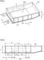
- FIG. 2 and 3 is a perspective view showing case member 200 that accommodates battery cells 100.
- a below-described cover portion of case member 200 is not shown.
- case member 200 includes an inner space 200A, a bottom surface member 210, a cooling plate 220, side surface members 230, and reinforcing ribs 240.
- Stacks (battery assemblies) of the plurality of battery cells 100 stacked in the Y axis direction are accommodated in inner space 200A.
- the battery assemblies are arranged in three rows in the X axis direction.
- Cooling plate 220 and side surface members 230 define inner space 200A.
- Cooling plate 220 is provided on bottom surface member 210. Cooling plate 220 includes: a first portion 221 facing inner space 200A; and a second portion 222 located on an outer side with respect to first portion 221 and not facing inner space 200A.
- Each of side surface members 230 includes an upper flange portion 231 (first flange), a lower flange portion 232 (second flange), and a side surface portion 233 (frame portion). Second portion 222 of cooling plate 220 is interposed between lower flange portion 232 of side surface member 230 and bottom surface member 210.
- Side surface portion 233 of side surface member 230 constitutes a side surface of case member 200.
- Side surface portions 233 include: a portion extending in a direction orthogonal to the Y axis direction; and a portion extending in a direction orthogonal to the X axis direction.
- Side surface portion 233 connects upper flange portion 231 and lower flange portion 232.
- Upper flange portion 231 (first flange), lower flange portion 232 (second flange), and side surface portion 233 (frame portion) constitute a U-shaped cross section.
- Side surface portions 233 which are located on both sides in the Y axis direction with respect to the stacks (including separators) of battery cells 100 and extend in the direction orthogonal to the Y axis direction, directly support the stacks of battery cells 100 (Cell-to-Pack structure). At portions ⁇ of side surface portions 233 in Fig. 3 , the stacks of battery cells 100 are in abutment with side surface portions 233.
- case member 200 is not limited to one in which side surface portions 233 directly support the stacks of battery cells 100, and may be one (Cell-Module-Pack structure) in which a battery module including the plurality of battery cells 100 is accommodated.
- Reinforcing ribs 240 are provided on each of side surface portions 233 extending in a direction orthogonal to the Y axis direction. Reinforcing ribs 240 may be provided on each of side surface portions 233 extending in a direction orthogonal to the X axis direction. Reinforcing ribs 240 are provided to extend in the Z axis direction. Reinforcing ribs 240 may be provided to extend in a direction obliquely intersecting the Z axis direction.
- the plurality of reinforcing ribs 240 are provided side by side in the X axis direction.
- One reinforcing rib 240 may be provided.
- Each of reinforcing ribs 240 extends across a whole of side surface portion 233 in the Z axis direction. Reinforcing rib 240 may be provided to extend across a portion thereof in the Z axis direction.
- Lower flange portion 232 is in abutment with second portion 222 of cooling plate 220.
- Upper flange portion 231 is formed at an upper end portion of side surface member 230, i.e., an end portion opposite to cooling plate 220 in the Z axis direction.
- Upper flange portion 231 is formed to be separated from second portion 222 of cooling plate 220 and lower flange portion 232 along the Z axis direction and is formed in parallel with second portion 222 and lower flange portion 232.
- Upper flange portion 231 protrudes with respect to side surface portion 233 in the same direction as those of second portion 222 of cooling plate 220 and lower flange portion 232.
- Second portion 222 of cooling plate 220 protrudes on an outer side with respect to side surface portion 233 of side surface member 230.
- Reinforcing rib 240 is formed to extend from upper flange portion 231 to reach lower flange portion 232.
- Reinforcing rib 240 may be composed of the same material as a material of side surface member 230, or may be composed of a material different from the material of side surface member 230.
- Reinforcing rib 240 may be composed of, for example, a steel plate, aluminum, or resin.
- Reinforcing ribs 240 are joined to upper flange portion 231, side surface portion 233, and lower flange portion 232. This joining is performed by welding or the like, for example. Preferably, all the portions at which reinforcing ribs 240 and side surface member 230 face one another are welded.
- Fig. 4 is a side view of case member 200.
- reinforcing ribs 240 include a first rib 241, a second rib 242, a third rib 243, and a fourth rib 244.
- First rib 241, second rib 242, third rib 243, and fourth rib 244 are provided to be separated from one another along the X axis direction.
- Second rib 242 is provided on the central axis of the stack of battery cells 100 located at the center of the three rows in the X axis direction. Second rib 242 is arranged to be separated by a distance B from side surface portion 233 on the left side in Fig. 4 (reference side surface in the reinforcing rib arrangement). Second rib 242 is located on the central axis of battery cells 100 located at the center of the three rows.
- First rib 241 is arranged to be separated by a distance B/2 from side surface portion 233 on the left side in Fig. 4 .
- First rib 241 is provided at a position that corresponds to the stack of battery cells 100 located on the left side among the three rows in the figure and that is separated from the central axis of battery cells 100.
- Third rib 243 is arranged to be separated from second rib 242 by distance B/2. Third rib 243 is provided at a position that corresponds to the stack of battery cells 100 located on the right side among the three rows in the figure and that is separated from the central axis of battery cells 100.
- Fourth rib 244 is arranged to be separated from third rib 243 by a distance D. Distance D is different from distance B/2. Fourth rib 244 is provided at a position separated from the central axis of battery cells 100. Preferably, fourth rib 244 is arranged along an edge end or vicinity of the edge end of portion ⁇ (rightmost portion ⁇ of three portions ⁇ shown in Fig. 4 ) with which the stack of battery cells 100 separated the most from side surface portion 233 on the left side in Fig. 4 (reference side surface in the reinforcing rib arrangement) is in abutment, the edge end being located on a side far away from the reference side surface (right side in Fig. 4 ).
- Fig. 5 is an external view of the battery pack. As shown in Fig. 5 , a cover member 250 is assembled to side surface members 230 to seal inner space 200A of case member 200.
- the battery pack includes an entrance portion 300, an exit portion 400, and a coolant tube 500. Coolant is supplied from entrance portion 300 through coolant tube 500 to a coolant path formed in cooling plate 220, and the coolant is discharged from exit portion 400 through coolant tube 500. Water is used as the coolant, but the coolant is not limited thereto.
- Coolant tube 500 is provided to extend along side surface portion 233. Coolant tube 500 is supported by a supporting portion 2400 provided in reinforcing rib 240. Supporting portion 2400 may be constituted of a through hole provided in reinforcing rib 240.
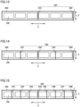
- FIG. 6 shows an exemplary reinforcing rib arrangement 240.
- a first rib 241, a second rib 242, a third rib 243, and a fourth rib 244 are arranged for three rows of stacks of battery cells 100.
- a first rib 241 and a second rib 242 are arranged at positions to avoid battery cells 100.
- a first rib 241, a second rib 242, a third rib 243, and a fourth rib 244 are arranged at positions to avoid battery cells 100.
- a first rib 241, a second rib 242, a third rib 243, and a fourth rib 244 are arranged at positions to avoid battery cells 100.
- a first rib 241, a third rib 243, a fifth rib 245, and a seventh rib 247 are arranged on central axes of battery cells 100, and a second rib 242, a fourth rib 244, a sixth rib 246, and an eighth rib 248 are arranged at positions to avoid battery cells 100.
- a first rib 241 is arranged on a central axis of battery cells 100, and a second rib 242 is arranged at a position to avoid battery cells 100.
- a second rib 242 is arranged on a central axis of battery cells 100, a first rib 241 and a third rib 243 are arranged at positions that correspond to battery cells 100 and that are separated from the central axes of battery cells 100, and a fourth rib 244 is arranged at a position to avoid battery cells 100.
- a first rib 241 is arranged on a central axis of battery cells 100
- a third rib 243 are arranged at positions that correspond to battery cells 100 and that are separated from the central axes of battery cells 100
- a fourth rib 244 is arranged at a position to avoid battery cells 100.
- a fourth rib 244 is arranged on a central axis of battery cells 100, a first rib 241, a second rib 242, a fifth rib 245, a sixth rib 246, and a seventh rib 247 are arranged at positions that correspond to battery cells 100 and that are separated from the central axes of battery cells 100, and a third rib 243 and an eighth rib 248 are arranged at positions to avoid battery cells 100.
- a first rib 241 and a second rib 242 are arranged at positions to avoid battery cells 100.
- a first rib 241 and a third rib 243 are arranged on central axes of battery cells 100, and a second rib 242 and a fourth rib 244 are arranged at positions to avoid battery cells 100.
- a first rib 241 and a third rib 243 are arranged on central axes of battery cells 100
- a second rib 242 and a fourth rib 244 are arranged at positions to avoid battery cells 100.
- a second rib 242 and a sixth rib 246 are arranged on central axes of battery cells 100, a first rib 241, a third rib 243, a fifth rib 245, and a seventh rib 247 are arranged at positions that correspond to battery cells 100 and that are separated from the central axes of battery cells 100, and a fourth rib 244 and an eighth rib 248 are arranged at positions to avoid battery cells 100.
- all reinforcing ribs 240 may be arranged at positions other than the center of the pressure receiving surface (the central axis of battery cells 100 in the X axis direction), or part of reinforcing ribs 240 may be arranged at position(s) other than the center of the pressure receiving surface.
- the plurality of reinforcing ribs 240 are sequentially arranged side by side from the reference side surface in the reinforcing rib arrangement at intervals each corresponding to the reinforcing rib arrangement distance (B/2), which is a distance that is 1/2 (or an inverse of an integer such as 1/4 or 1/8) time as large as the reference distance (B) that is a distance between the central axis of the plurality of rows of the stacks of battery cells 100 in the X axis direction in case member 200 and side surface portion 233 (reference side surface in the reinforcing rib arrangement) of case member 200 along the Y axis direction.
- B/2 is a distance that is 1/2 (or an inverse of an integer such as 1/4 or 1/8) time as large as the reference distance (B) that is a distance between the central axis of the plurality of rows of the stacks of battery cells 100 in the X axis direction in case member 200 and side surface portion 233 (reference side surface in the reinforcing rib arrangement) of
- reinforcing rib 240 is arranged along the edge end or vicinity of the edge end of portion ⁇ with which the stack of battery cells 100 furthest away from the reference side surface in the reinforcing rib arrangement is in abutment, the edge end being located on the side far away from the reference side surface.
- Fig. 16 is a perspective view showing a modification of case member 200 (except for cover member 250).
- a reinforcing rib 240A extending in the X axis direction (or the Y axis direction) may be provided in addition to reinforcing ribs extending in a direction inclined obliquely with respect to the Z axis direction.
- a reinforcing rib 240A extending in the X axis direction (or the Y axis direction) may be provided.
- reinforcing rib 240A By adding reinforcing rib 240A, the amount of deformation of side surface portion 233 of case member 200 can be more effectively suppressed. Further, the structures and arrangements of reinforcing ribs 240 are not necessarily limited to those described above. For example, the plurality of reinforcing ribs 240 may be arranged at equal intervals, or the plurality of reinforcing ribs 240 may be arranged at different intervals.
- Fig. 17 is an enlarged view of supporting portion 2400 for coolant tube 500.
- supporting portion 2400 is constituted of a substantially circular through hole provided in reinforcing rib 240.
- the shape of the through hole can be appropriately changed.
- a cushion material may be provided at a contact portion between supporting portion 2400 and coolant tube 500.
Landscapes
- Chemical & Material Sciences (AREA)
- Chemical Kinetics & Catalysis (AREA)
- Electrochemistry (AREA)
- General Chemical & Material Sciences (AREA)
- Engineering & Computer Science (AREA)
- Manufacturing & Machinery (AREA)
- Aviation & Aerospace Engineering (AREA)
- Battery Mounting, Suspending (AREA)
- Secondary Cells (AREA)
Applications Claiming Priority (1)
| Application Number | Priority Date | Filing Date | Title |
|---|---|---|---|
| JP2022028193A JP7696307B2 (ja) | 2022-02-25 | 2022-02-25 | 電池パック |
Publications (2)
| Publication Number | Publication Date |
|---|---|
| EP4235923A2 true EP4235923A2 (de) | 2023-08-30 |
| EP4235923A3 EP4235923A3 (de) | 2023-11-01 |
Family
ID=85199442
Family Applications (1)
| Application Number | Title | Priority Date | Filing Date |
|---|---|---|---|
| EP23155391.8A Pending EP4235923A3 (de) | 2022-02-25 | 2023-02-07 | Batteriepack |
Country Status (4)
| Country | Link |
|---|---|
| US (1) | US20230275304A1 (de) |
| EP (1) | EP4235923A3 (de) |
| JP (1) | JP7696307B2 (de) |
| CN (1) | CN116666869A (de) |
Families Citing this family (3)
| Publication number | Priority date | Publication date | Assignee | Title |
|---|---|---|---|---|
| US11996576B2 (en) * | 2020-07-03 | 2024-05-28 | Teijin Automotive Technologies, Inc. | Impact resistant frame of battery containment system |
| KR102628969B1 (ko) * | 2023-09-27 | 2024-01-24 | 주식회사케이에스엠 | 전기차 배터리 케이스 제조방법 |
| KR20250132888A (ko) * | 2024-02-29 | 2025-09-05 | 주식회사 엘지에너지솔루션 | 배터리 팩 케이스, 배터리 팩, 및 이를 포함하는 배터리 장치 |
Citations (3)
| Publication number | Priority date | Publication date | Assignee | Title |
|---|---|---|---|---|
| JP2012104467A (ja) | 2010-11-12 | 2012-05-31 | Sb Limotive Co Ltd | 電池モジュール |
| JP2019197622A (ja) | 2018-05-08 | 2019-11-14 | トヨタ自動車株式会社 | 電池パック |
| JP2022028193A (ja) | 2020-08-03 | 2022-02-16 | 東芝エレベータ株式会社 | 乗客コンベア |
Family Cites Families (17)
| Publication number | Priority date | Publication date | Assignee | Title |
|---|---|---|---|---|
| JPH087860A (ja) * | 1994-06-24 | 1996-01-12 | Makita Corp | バッテリーケース |
| JP2008166060A (ja) * | 2006-12-27 | 2008-07-17 | Sanyo Electric Co Ltd | パック電池 |
| JP5183074B2 (ja) * | 2007-02-05 | 2013-04-17 | 三洋電機株式会社 | パック電池 |
| JP5490406B2 (ja) * | 2008-12-27 | 2014-05-14 | 三洋電機株式会社 | 車両用の電源装置 |
| US9263713B2 (en) * | 2010-05-26 | 2016-02-16 | Samsung Sdi Co., Ltd. | Battery pack |
| US9065111B2 (en) * | 2010-05-26 | 2015-06-23 | Samsung Sdi Co., Ltd. | Battery pack |
| JP5541100B2 (ja) | 2010-11-10 | 2014-07-09 | 三菱自動車工業株式会社 | 電池パックトレー |
| JP6091783B2 (ja) * | 2012-07-17 | 2017-03-08 | 株式会社東芝 | 電池パック |
| WO2016175270A1 (ja) * | 2015-04-28 | 2016-11-03 | 日本電気株式会社 | 蓄電装置および補強構造 |
| JP6777580B2 (ja) * | 2017-03-29 | 2020-10-28 | 株式会社Subaru | 車載用バッテリー |
| CN207651567U (zh) | 2017-12-28 | 2018-07-24 | 重庆仟和镁业科技有限公司 | 一种用于轻型电动卡车的镁合金电池箱壳体 |
| FR3062521B1 (fr) | 2018-04-10 | 2023-09-08 | Sogefi Air & Cooling | Unite de batterie avec des moyens de regulation de la temperature integres au boitier |
| JP6876745B2 (ja) | 2019-05-16 | 2021-05-26 | 本田技研工業株式会社 | 車両用バッテリユニット |
| JP7048545B2 (ja) | 2019-07-24 | 2022-04-05 | 本田技研工業株式会社 | セル固定機構、バッテリパック及びセル固定方法 |
| EP3836242B1 (de) | 2019-12-11 | 2023-08-09 | GF Casting Solutions AG | Batteriewanne |
| JP2021138187A (ja) | 2020-03-02 | 2021-09-16 | トヨタ自動車株式会社 | 車体下部構造 |
| WO2022006252A1 (en) | 2020-07-03 | 2022-01-06 | Teijin Limited | Battery tray made of integrally molded fiber reinforced plastics |
-
2022
- 2022-02-25 JP JP2022028193A patent/JP7696307B2/ja active Active
-
2023
- 2023-02-07 EP EP23155391.8A patent/EP4235923A3/de active Pending
- 2023-02-17 CN CN202310132437.XA patent/CN116666869A/zh active Pending
- 2023-02-22 US US18/173,044 patent/US20230275304A1/en active Pending
Patent Citations (3)
| Publication number | Priority date | Publication date | Assignee | Title |
|---|---|---|---|---|
| JP2012104467A (ja) | 2010-11-12 | 2012-05-31 | Sb Limotive Co Ltd | 電池モジュール |
| JP2019197622A (ja) | 2018-05-08 | 2019-11-14 | トヨタ自動車株式会社 | 電池パック |
| JP2022028193A (ja) | 2020-08-03 | 2022-02-16 | 東芝エレベータ株式会社 | 乗客コンベア |
Also Published As
| Publication number | Publication date |
|---|---|
| EP4235923A3 (de) | 2023-11-01 |
| JP2023124438A (ja) | 2023-09-06 |
| US20230275304A1 (en) | 2023-08-31 |
| JP7696307B2 (ja) | 2025-06-20 |
| CN116666869A (zh) | 2023-08-29 |
Similar Documents
| Publication | Publication Date | Title |
|---|---|---|
| EP4235923A2 (de) | Batteriepack | |
| US7794870B2 (en) | Battery suitable for preparation of battery module | |
| US12525667B2 (en) | Battery module | |
| CN115066795B (zh) | 电池组和包括该电池组的设备 | |
| US20210151722A1 (en) | Battery pack | |
| US20230099870A1 (en) | Battery module | |
| US20250118843A1 (en) | Battery pack | |
| US20240170794A1 (en) | Battery Module | |
| JP2023114147A (ja) | 電池パック | |
| US20240304915A1 (en) | Battery pack | |
| US12095104B2 (en) | Battery pack and battery holder | |
| EP4435955A1 (de) | Batteriepack | |
| US20230275284A1 (en) | Battery pack | |
| US20250118854A1 (en) | Battery pack | |
| US20250226520A1 (en) | Battery assembly | |
| US20260066479A1 (en) | Battery assembly and battery pack | |
| US20240128544A1 (en) | Battery pack | |
| EP4203154B1 (de) | Batteriemodul | |
| US20260058253A1 (en) | Battery assembly | |
| EP4697456A1 (de) | Batterieanordnung | |
| US20240136637A1 (en) | Battery module | |
| US20260074345A1 (en) | Battery assembly | |
| US20240291093A1 (en) | Battery pack and method of manufacturing same | |
| US20240429519A1 (en) | Battery pack | |
| US20240429539A1 (en) | Battery pack |
Legal Events
| Date | Code | Title | Description |
|---|---|---|---|
| PUAI | Public reference made under article 153(3) epc to a published international application that has entered the european phase |
Free format text: ORIGINAL CODE: 0009012 |
|
| STAA | Information on the status of an ep patent application or granted ep patent |
Free format text: STATUS: REQUEST FOR EXAMINATION WAS MADE |
|
| 17P | Request for examination filed |
Effective date: 20230207 |
|
| AK | Designated contracting states |
Kind code of ref document: A2 Designated state(s): AL AT BE BG CH CY CZ DE DK EE ES FI FR GB GR HR HU IE IS IT LI LT LU LV MC ME MK MT NL NO PL PT RO RS SE SI SK SM TR |
|
| PUAL | Search report despatched |
Free format text: ORIGINAL CODE: 0009013 |
|
| AK | Designated contracting states |
Kind code of ref document: A3 Designated state(s): AL AT BE BG CH CY CZ DE DK EE ES FI FR GB GR HR HU IE IS IT LI LT LU LV MC ME MK MT NL NO PL PT RO RS SE SI SK SM TR |
|
| RIC1 | Information provided on ipc code assigned before grant |
Ipc: H01M 10/6556 20140101ALI20230925BHEP Ipc: H01M 10/6554 20140101ALI20230925BHEP Ipc: H01M 10/625 20140101ALI20230925BHEP Ipc: H01M 10/613 20140101ALI20230925BHEP Ipc: H01M 50/249 20210101ALI20230925BHEP Ipc: H01M 50/242 20210101ALI20230925BHEP Ipc: H01M 50/236 20210101ALI20230925BHEP Ipc: H01M 50/209 20210101AFI20230925BHEP |