EP4236061A2 - Abdeckvorrichtung - Google Patents
Abdeckvorrichtung Download PDFInfo
- Publication number
- EP4236061A2 EP4236061A2 EP23181546.5A EP23181546A EP4236061A2 EP 4236061 A2 EP4236061 A2 EP 4236061A2 EP 23181546 A EP23181546 A EP 23181546A EP 4236061 A2 EP4236061 A2 EP 4236061A2
- Authority
- EP
- European Patent Office
- Prior art keywords
- roof
- metal plate
- area
- covering
- covering device
- Prior art date
- Legal status (The legal status is an assumption and is not a legal conclusion. Google has not performed a legal analysis and makes no representation as to the accuracy of the status listed.)
- Pending
Links
Images

Classifications
-
- E—FIXED CONSTRUCTIONS
- E04—BUILDING
- E04D—ROOF COVERINGS; SKY-LIGHTS; GUTTERS; ROOF-WORKING TOOLS
- E04D13/00—Special arrangements or devices in connection with roof coverings; Protection against birds; Roof drainage ; Sky-lights
- E04D13/14—Junctions of roof sheathings to chimneys or other parts extending above the roof
- E04D13/147—Junctions of roof sheathings to chimneys or other parts extending above the roof specially adapted for inclined roofs
- E04D13/1473—Junctions of roof sheathings to chimneys or other parts extending above the roof specially adapted for inclined roofs specially adapted to the cross-section of the parts extending above the roof
-
- F—MECHANICAL ENGINEERING; LIGHTING; HEATING; WEAPONS; BLASTING
- F24—HEATING; RANGES; VENTILATING
- F24S—SOLAR HEAT COLLECTORS; SOLAR HEAT SYSTEMS
- F24S25/00—Arrangement of stationary mountings or supports for solar heat collector modules
- F24S25/60—Fixation means, e.g. fasteners, specially adapted for supporting solar heat collector modules
- F24S25/61—Fixation means, e.g. fasteners, specially adapted for supporting solar heat collector modules for fixing to the ground or to building structures
- F24S25/613—Fixation means, e.g. fasteners, specially adapted for supporting solar heat collector modules for fixing to the ground or to building structures in the form of bent strips or assemblies of strips; Hook-like connectors; Connectors to be mounted between building-covering elements
-
- H—ELECTRICITY
- H02—GENERATION; CONVERSION OR DISTRIBUTION OF ELECTRIC POWER
- H02S—GENERATION OF ELECTRIC POWER BY CONVERSION OF INFRARED RADIATION, VISIBLE LIGHT OR ULTRAVIOLET LIGHT, e.g. USING PHOTOVOLTAIC [PV] MODULES
- H02S20/00—Supporting structures for PV modules
- H02S20/20—Supporting structures directly fixed to an immovable object
- H02S20/22—Supporting structures directly fixed to an immovable object specially adapted for buildings
- H02S20/23—Supporting structures directly fixed to an immovable object specially adapted for buildings specially adapted for roof structures
-
- H—ELECTRICITY
- H02—GENERATION; CONVERSION OR DISTRIBUTION OF ELECTRIC POWER
- H02S—GENERATION OF ELECTRIC POWER BY CONVERSION OF INFRARED RADIATION, VISIBLE LIGHT OR ULTRAVIOLET LIGHT, e.g. USING PHOTOVOLTAIC [PV] MODULES
- H02S30/00—Structural details of PV modules other than those related to light conversion
-
- E—FIXED CONSTRUCTIONS
- E04—BUILDING
- E04D—ROOF COVERINGS; SKY-LIGHTS; GUTTERS; ROOF-WORKING TOOLS
- E04D13/00—Special arrangements or devices in connection with roof coverings; Protection against birds; Roof drainage ; Sky-lights
- E04D13/14—Junctions of roof sheathings to chimneys or other parts extending above the roof
- E04D13/147—Junctions of roof sheathings to chimneys or other parts extending above the roof specially adapted for inclined roofs
- E04D13/1473—Junctions of roof sheathings to chimneys or other parts extending above the roof specially adapted for inclined roofs specially adapted to the cross-section of the parts extending above the roof
- E04D13/1476—Junctions of roof sheathings to chimneys or other parts extending above the roof specially adapted for inclined roofs specially adapted to the cross-section of the parts extending above the roof wherein the parts extending above the roof have a generally circular cross-section
-
- Y—GENERAL TAGGING OF NEW TECHNOLOGICAL DEVELOPMENTS; GENERAL TAGGING OF CROSS-SECTIONAL TECHNOLOGIES SPANNING OVER SEVERAL SECTIONS OF THE IPC; TECHNICAL SUBJECTS COVERED BY FORMER USPC CROSS-REFERENCE ART COLLECTIONS [XRACs] AND DIGESTS
- Y02—TECHNOLOGIES OR APPLICATIONS FOR MITIGATION OR ADAPTATION AGAINST CLIMATE CHANGE
- Y02B—CLIMATE CHANGE MITIGATION TECHNOLOGIES RELATED TO BUILDINGS, e.g. HOUSING, HOUSE APPLIANCES OR RELATED END-USER APPLICATIONS
- Y02B10/00—Integration of renewable energy sources in buildings
- Y02B10/10—Photovoltaic [PV]
-
- Y—GENERAL TAGGING OF NEW TECHNOLOGICAL DEVELOPMENTS; GENERAL TAGGING OF CROSS-SECTIONAL TECHNOLOGIES SPANNING OVER SEVERAL SECTIONS OF THE IPC; TECHNICAL SUBJECTS COVERED BY FORMER USPC CROSS-REFERENCE ART COLLECTIONS [XRACs] AND DIGESTS
- Y02—TECHNOLOGIES OR APPLICATIONS FOR MITIGATION OR ADAPTATION AGAINST CLIMATE CHANGE
- Y02E—REDUCTION OF GREENHOUSE GAS [GHG] EMISSIONS, RELATED TO ENERGY GENERATION, TRANSMISSION OR DISTRIBUTION
- Y02E10/00—Energy generation through renewable energy sources
- Y02E10/50—Photovoltaic [PV] energy
Definitions
- the invention relates to a covering device for covering a fastening area of a roof for fastening a solar panel or a photovoltaic module.
- roof hooks To mount a mounting rail for a solar panel or a photovoltaic module on a pitched roof, roof hooks must be guided through the existing roof covering.
- roof tiles are mechanically processed for this purpose, which is associated with a comparatively high level of effort and can also lead to leaks in the roofing.
- High snow loads can also cause a tile to break if the snow load on the solar panels or the photovoltaic modules is too high and the roof hooks are supported on the roof tiles.
- a rooftop mounting device is known.
- a rectangular cover part replaces a roof tile.
- a cover encloses a base hook to which, for example, a photovoltaic module can be attached.
- the disadvantage of this is that the cover part is comparatively unstable and can easily bend. Rainwater also runs off uncontrolled. Furthermore, the cover is not tight, so dirt and/or water can penetrate.
- the covering device according to the invention is designed to cover a fastening area of a roof for fastening a solar panel or a photovoltaic module or can be used for this purpose.
- the roof can be a pitched roof, for example.
- a roof hook is preferably attached to the roof in the attachment area.
- the roof hook can be screwed to a roof batten and/or a roof beam.
- the roof hook can be mounted on a roof batten and/or a roof beam.
- a solar panel or photovoltaic module can be attached directly or indirectly to the roof hook, e.g. via a mounting rail.
- the mounting rail can be attached horizontally or vertically to the roof hook.
- the covering device has a metal plate.
- the metal plate may preferably be formed in a rectangular shape such as a square.
- the metal plate can have a height between 30 cm and 60 cm, preferably between 45 cm and 55 cm.
- the width can be, for example, between 40 cm and 70 cm, preferably between 50 cm and 60 cm.
- the metal plate can, for example, replace at least or exactly one, two, three or four roof tiles.
- the dimensions can be of any size and can be adapted to the respective requirements.
- the metal plate can be moved to the desired position on the roof. Due to the dimensioning, there is a certain amount of play in order to take account of the individual circumstances on the roof, e.g. the position of roof battens and/or roof beams.
- the thickness of the metal plate can be, for example, between 0.1 mm and 3 mm, preferably between 0.1 mm and 1 mm, particularly preferably between 0.1 mm and 0.5 mm, for example 0.3 mm. Due to the small thickness of the metal plate, it can behave like a foil.
- the metal plate is therefore preferably light in weight, which makes handling easier.
- the metal plate may include or consist of an aluminum and/or lead material.
- the metal plate is preferably a rolled sheet of aluminum and/or sheet of lead.
- the metal plate has a recess for a roof hook.
- the recess is preferably arranged centrally and/or in the middle.
- the recess is preferably completely enclosed by the metal plate, i.e. the recess is not open at the side.
- the recess can be round, eg circular, oval or angular, eg rectangular, eg square.
- an oval recess can have a height of between 5 cm and 20 cm, preferably between 10 cm and 15 cm.
- the width can be, for example, between 3 cm and 10 cm, preferably between 5 cm and 7 cm.
- the recess can preferably be created by a cutting and/or machining process, e.g. cutting, turning, drilling, milling and/or grinding.
- the recess can also be punched out, blasted out or lasered out.
- the roof hook can, for example, be attached to a roof batten and/or a roof beam, e.g. screwed.
- the roof hook can be guided through the metal plate through the recess.
- the metal plate has a deformable, ie preferably bendable and/or flexible, adjustment area or adjustment section.
- the fitting area is plate-shaped. The deformability can be ensured, for example, via the thickness of the metal plate and/or the material of the metal plate.
- the adjustment area is preferably a lower area in the installed state, e.g. the lower third, fourth, fifth, sixth or seventh, of the metal plate.
- the adjustment area can be adapted to the shape of the roof tiles adjoining the covering device, preferably underneath.
- the adjustment area can be shaped and/or pressed onto the contour of the roof tile by hand during assembly.
- the fitting area and the roof tiles overlap.
- the metal plate has a cover area or cover section, the cover area having corrugations.
- the cover portion is plate-shaped.
- the corrugations increase the stability of the metal plate.
- the metal plate does not sag.
- the metal plate can first be rolled. Corrugation can then be introduced, for example by means of one or more embossing rollers.
- corrugations is to be understood broadly and also includes, for example, wavy, sawtooth, rectangular and/or trapezoidal patterns.
- the corrugation is provided, for example, on the top and/or bottom of the metal plate.
- the corrugation is preferably present both on the upper side and on the lower side.
- mountains on the top can form valleys on the bottom and vice versa.
- the corrugations are preferably arranged in the longitudinal direction. Soiling and/or water can thus be discharged in a controlled manner from top to bottom. For example, water can be discharged when there is wind.
- the wind for example, cannot easily drive the water sideways under the covering, since there are no-wind zones in the valleys of the corrugation.
- the metal plate is preferably formed in one piece.
- the cover area and the adjustment area can be formed in one piece.
- the covering area and the adjustment area preferably have the same material. Consequently, no separate material is required to adapt to the shape of the roof tiles. As a result, the manufacturing costs can be kept low.
- the covering area and the adjustment area preferably merge into one another.
- the coverage area and the fitting area are of the same width.
- the covering device has a rubber sleeve that encloses the recess, preferably completely.
- the rubber coating can be, for example, foam rubber, e.g. made from ethylene propylene diene (monomer) rubber (EPDM).
- foam rubber is UV-resistant.
- the rubber sleeve can preferably taper towards the top.
- an elongated slot can be provided at the upper end of the rubber sleeve.
- a roof hook can be pushed through the slot.
- the rubber material can preferably have a certain amount of play. Different roof hooks that have smaller deviations in terms of width and/or thickness can also be used.
- the upper end of the rubber sleeve is in full contact with the roof hook.
- the area in which a roof hook is guided through the recess is sealed by the rubber sleeve.
- the adjustment area is free of corrugations.
- the adjustment area can already have no corrugations from the outset.
- this area can first be corrugated and then pressed flat and/or rolled, for example for manufacturing reasons.
- the entire metal plate can first be corrugated and then the corrugations can be flattened in the areas where no corrugation is desired.
- the adjustment area is free of corrugations, it can be easily deformed and e.g. adapted to the shape of the adjoining roof tiles.
- an upper area of the metal plate in the installed state can also be free of corrugations. This can make bending easier, for example.
- the metal plate is folded or folded up on at least one side.
- the metal plate is preferably folded or folded up on three sides.
- the fold is made, for example, upwards, preferably in the direction of the rubber sleeve.
- At least one edge of the metal plate can be bent or folded inwards. This can prevent dirt and/or water from penetrating, e.g. melt water and/or driving rain.
- the folded edge may, for example, have a width of between 1 cm and 5 cm, preferably between 2 cm and 4 cm, for example 3 cm.
- a rubber coating and/or a foam strip can optionally be provided on the edges.
- the rubber coating and/or the foam strip can have a triangular cross-sectional area, for example.
- the rubber coating and/or the foam strip can have a height of between 1 cm and 5 cm, preferably between 2 cm and 4 cm, for example 3 cm.
- the width can be, for example, between 0.5 cm and 4 cm, preferably between 1 cm and 3 cm, for example 2 cm.
- the rubber coating and/or the foam strip can, for example, provide a lateral seal.
- the rubber coating can, for example, be foam rubber, e.g. made of EPDM.
- the rubber and/or foam tape can be glued to three sides of the metal plate, for example, to prevent moisture from penetrating under the roof covering.
- a preferably double-adhesive sealing tape can be provided at the lower edge.
- the rubber sleeve is attached to the top of the metal plate, preferably riveted.
- the rubber sleeve seals the recess. Because the rubber sleeve is attached to the top of the metal plate, no dirt and/or water can get under the metal plate.
- a simple and inexpensive attachment can be achieved by riveting.
- a fastening frame is provided for fastening the rubber sleeve.
- a lower edge of the rubber sleeve can, for example, rest on the metal plate and be secured from above with the fastening frame.
- the mounting frame can have or consist of a metal material, for example.
- the mounting frame is preferably designed, for example, as a mounting ring, mounting oval or mounting rectangle.
- the mounting frame can, for example, have a width of between 0.5 cm and 3 cm, preferably between 0.5 cm and 1 cm.
- the mounting frame can be adapted to the shape of the recess.
- the mounting frame can preferably completely enclose the recess.
- a protective device for the rubber sleeve is provided on the upper side of the metal plate.
- the protective device can be designed as an angle, for example.
- the protective device In the mounted state, the protective device can be arranged above the rubber sleeve.
- the protective device protects the rubber sleeve from ice and/or snow sliding off, for example.
- the protective device can be designed as a separate component and can be fastened directly to the metal plate, for example.
- the protective device can be formed on and/or connected to the attachment ring.
- a stabilizing device is provided on the underside of the metal plate.
- the stabilizing device can be fastened, e.g. centrally, to the underside of the metal plate, for example glued and/or riveted.
- the stabilization device can be arranged, for example, in an upper area and/or in the area of the recess in the metal plate.
- the stabilization device can be plate-shaped.
- the stabilizing device is smaller than the metal plate.
- the area of the stabilizing device is at most 1/2, 1/3, 1/4, 1/5 or 1/6 as large as the area of the metal plate. The stabilization device thus only stabilizes a section of the metal plate.
- the stabilization device can, for example, comprise or consist of a metal material.
- the stabilization device has an opening for a roof hook.
- the opening preferably has the same shape and/or size as the recess in the metal plate.
- the opening may be below the recess to create a common passage for a roof hook.
- a roof hook can thus be passed through the opening of the stabilization device and through the recess in the metal plate.
- the stabilization device is folded on at least one side.
- the stabilization device is preferably folded on three sides.
- the fold is made e.g. downwards, preferably in the direction of a roof batten or a roof beam.
- the fold can preferably extend at right angles to the actual stabilization device.
- An upper edge can be used here, for example, for hanging in a roof batten or a roof beam.
- Lateral bevels can increase stability.
- the invention also relates to a system with a covering device according to the invention and a roof hook for fastening a solar panel or a photovoltaic module.
- the roof hook is guided through the recess in the metal plate and the rubber sleeve.
- a solar panel or photovoltaic module can be attached directly or indirectly to the roof hook, e.g. via a mounting rail.
- the covering device ensures that the fastening area is covered or sealed.
- the invention also relates to a method for fastening a roof hook to a roof with a covering device according to the invention or a system according to the invention.
- the position of the roof hooks is preferably determined and/or the roof covering is uncovered in the fastening area. This makes the roof battens and/or roof beams accessible.
- the roof hook is attached, e.g. screwed, to a roof batten and/or a roof beam, for example.
- the covering device is slipped over the roof hook.
- the roof hook is preferably now accommodated in the rubber sleeve.
- the covering device can be aligned and/or the adjacent roof tiles can be covered again.
- the adjustment area of the metal plate is shaped or pressed onto the roof tiles that are attached below.
- All of the embodiments and components of the devices described here are preferably designed to be assembled using the method described here. Furthermore, all of the embodiments of the devices described here and all of the embodiments of the method described here can be combined with one another, preferably also detached from the specific configuration in the context of which they are mentioned.
- the illustrated embodiments are purely exemplary in nature.
- individual features can be used not only in the combination shown, but also on their own or in other technically sensible ways combinations can be realized.
- the features of one embodiment can be arbitrarily combined with features of another embodiment.
- a different roof hook can be used.
- the mounting frame and the stabilization device are optional.
- the metal plate can also be completely corrugated.
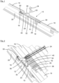
- FIGS 1 to 3 show a covering device 10 for covering a fastening area 12 of a roof 14 with roof tiles 16.
- the roof tiles 16 are suspended from roof battens 18, the roof battens 18 being fastened to roof beams 20.
- a mounting rail 24 for a solar panel or a photovoltaic module can be attached, e.g. clamped, to a roof hook 22 .
- the roof hook 22 can have a base 26 over which the roof hook 22 z. B. attached to the roof beam 20, for example screwed, is.
- the covering device 10 has a metal plate 28 with a cutout 30 for the roof hook 22 .
- the recess 30 is surrounded by a rubber sleeve 32 in which the roof hook 22 is arranged.
- the rubber sleeve 32 can be fastened, for example riveted, to the metal plate 28 via a fastening frame 34 .
- a protective device 36 for the rubber sleeve 32 can be formed on the fastening frame 34 .
- the covering device 10 has a deformable adjustment area 38 .
- the adjustment area 38 can be adjusted to the contour of the roof tile 16 adjoining it. For example, the adjustment area 38 can be pressed on by hand.
- the covering device 10 also has a covering area 40 with corrugations 42 .
- a stabilizing device 44 with folds 46 can be provided on the underside of the metal plate 28 .
- the metal plate 28 can be hung on the roof batten 18 via a front edge 46 .
- the stabilizing device 44 has an opening 48 through which the roof hook 22 is guided.
- the opening 48 can have the same shape as the recess 30 .
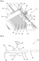
- the metal plate 28 can also be bent on three sides.
- the sides are bent upwards in the direction of the rubber sleeve 32 and form a kink 50. This prevents dirt and/or water from penetrating the roof.
Landscapes
- Engineering & Computer Science (AREA)
- Architecture (AREA)
- Civil Engineering (AREA)
- Structural Engineering (AREA)
- Physics & Mathematics (AREA)
- Life Sciences & Earth Sciences (AREA)
- Sustainable Development (AREA)
- Sustainable Energy (AREA)
- Thermal Sciences (AREA)
- Chemical & Material Sciences (AREA)
- Combustion & Propulsion (AREA)
- Mechanical Engineering (AREA)
- General Engineering & Computer Science (AREA)
- Roof Covering Using Slabs Or Stiff Sheets (AREA)
- Seal Device For Vehicle (AREA)
- Glass Compositions (AREA)
Abstract
Description
- Die Erfindung betrifft eine Abdeckvorrichtung zum Abdecken eines Befestigungsbereichs eines Dachs zur Befestigung eines Solarpanels oder eines Photovoltaikmoduls.
- Zur Montage einer Montageschiene für ein Solarpanel oder ein Photovoltaikmodul auf einem Schrägdach müssen Dachhaken durch die vorhandene Dacheindeckung geführt werden.
- Herkömmlich werden hierzu Dachziegel mechanisch bearbeitet, was mit einem vergleichsweise hohen Aufwand verbunden ist und zudem zu Undichtigkeiten in der Dacheindeckung führen kann.
- Auch können hohe Schneelasten einen Ziegelbruch verursachen, wenn die Schneelast auf den Solarpanelen oder den Photovoltaikmodulen zu hoch ist und sich die Dachhaken auf den Dachziegeln abstützen.
- Aus
AT 13559 U1 - Nachteilig daran ist, dass das Abdeckteil vergleichsweise instabil ist und sich leicht verbiegen kann. Auch läuft Regenwasser unkontrolliert ab. Ferner ist die Umhüllung nicht dicht, sodass dadurch Verschmutzungen und/oder Wasser eindringen können.
- Es ist daher eine Aufgabe der Erfindung, eine Abdeckvorrichtung sowie ein System zu schaffen, welche/s auf einfache und kostengünstige Weise ein Eindringen von Verschmutzungen und/oder Wasser verhindert.
- Die Lösung dieser Aufgabe erfolgt durch die Gegenstände der unabhängigen Ansprüche.
- Die erfindungsgemäße Abdeckvorrichtung ist zum Abdecken eines Befestigungsbereichs eines Dachs zur Befestigung eines Solarpanels oder eines Photovoltaikmoduls ausgebildet oder kann hierzu verwendet werden.
- Bei dem Dach kann es sich z.B. um ein Schrägdach handeln.
- Vorzugsweise wird im Befestigungsbereich ein Dachhaken am Dach befestigt. Beispielsweise kann der Dachhaken an einer Dachlatte und/oder einem Dachbalken verschraubt werden. Der Dachhaken kann, wie etwa eine Antenne, auf einer Dachlatte und/oder einem Dachbalken aufgeständert werden.
- Am Dachhaken kann unmittelbar oder mittelbar, z.B. über eine Montageschiene, ein Solarpanel oder ein Photovoltaikmodul befestigt werden. Die Montageschiene kann am Dachhaken horizontal oder vertikal befestigt werden.
- Die Abdeckvorrichtung weist eine Metallplatte auf.
- Die Metallplatte kann vorzugsweise rechteckförmig, z.B. quadratisch, ausgebildet sein.
- Beispielsweise kann die Metallplatte eine Höhe zwischen 30 cm und 60 cm, vorzugsweise zwischen 45 cm und 55 cm, aufweisen. Die Breite kann beispielsweise zwischen 40 cm und 70 cm, vorzugsweise zwischen 50 cm und 60 cm, betragen.
- Von der Abmessung kann die Metallplatte z.B. mindestens oder genau einen, zwei, drei oder vier Dachziegel ersetzen. Grundsätzlich ist die Abmessung jedoch beliebig groß und kann an die jeweiligen Erfordernisse angepasst werden.
- Beispielsweise kann die Metallplatte an die gewünschte Position auf dem Dach verschoben werden. Durch die Dimensionierung ist ein gewisses Spiel vorhanden, um den individuellen Gegebenheiten auf dem Dach, z.B. der Position von Dachlatten und/oder Dachbalken, Rechnung zu tragen.
- Die Stärke der Metallplatte kann beispielsweise zwischen 0,1 mm und 3 mm, vorzugsweise zwischen 0,1 mm und 1 mm, besonders bevorzugt zwischen 0,1 mm und 0,5 mm, z.B. 0,3 mm, betragen. Durch die geringe Stärke der Metallplatte kann sich diese wie eine Folie verhalten.
- Die Metallplatte weist somit vorzugsweise ein geringes Gewicht auf, was die Handhabung erleichtert.
- Beispielsweise kann die Metallplatte ein Aluminium- und/oder Bleimaterial umfassen oder daraus bestehen. Vorzugsweise handelt es sich bei der Metallplatte um ein gewalztes Aluminiumblech und/oder Bleiblech.
- Die Metallplatte weist eine Aussparung für einen Dachhaken auf. Die Aussparung ist vorzugsweise zentral und/oder mittig angeordnet. Vorzugsweise wird die Aussparung vollständig von der Metallplatte umschlossen, d.h. die Aussparung ist nicht seitlich offen.
- Beispielsweise kann die Aussparung rund, z.B. kreisförmig, oval oder eckig, beispielsweise rechteckförmig, z.B. quadratisch sein.
- Eine ovale Aussparung kann beispielsweise eine Höhe zwischen 5 cm und 20 cm, vorzugsweise zwischen 10 cm und 15 cm aufweisen. Die Breite kann beispielsweise zwischen 3 cm und 10 cm, vorzugsweise zwischen 5 cm und 7 cm, betragen.
- Die Aussparung kann vorzugsweise durch ein schneidendes und/oder zerspanendes Verfahren, z.B. Schneiden, Drehen, Bohren, Fräsen und/oder Schleifen, geschaffen werden. Auch kann die Aussparung ausgestanzt, ausgestrahlt oder ausgelasert sein.
- Der Dachhaken kann beispielsweise an einer Dachlatte und/oder einem Dachbalken befestigt, z.B. verschraubt werden. Durch die Aussparung kann der Dachhaken durch die Metallplatte geführt werden.
- Die Metallplatte weist einen verformbaren, also vorzugsweise biegbaren und/oder flexiblen, Anpassbereich bzw. Anpassabschnitt auf. Als Teil der Metallplatte ist der Anpassbereich plattenförmig. Die Verformbarkeit kann z.B. über die Dicke der Metallplatte und/oder das Material der Metallplatte gewährleistet werden.
- Bei dem Anpassbereich handelt es sich vorzugsweise um einen im montierten Zustand unteren Bereich, z.B. das untere Drittel, Viertel, Fünftel, Sechstel oder Siebtel, der Metallplatte.
- Der Anpassbereich kann an die Form der sich an die Abdeckvorrichtung, vorzugsweise darunter, anschließenden Dachziegel angepasst werden. Beispielsweise kann der Anpassbereich per Hand bei der Montage an die Kontur der Dachziegel angeformt und/oder angedrückt werden.
- Vorzugsweise überlappen der Anpassbereich und die Dachziegel.
- Auf diese Weise wird verhindert, dass Verschmutzungen und/oder Wasser am Übergang zwischen der Abdeckvorrichtung und den Dachziegeln eindringen. Beispielsweise Regen- und/oder Schmelzwasser können vielmehr ungehindert ablaufen.
- Die Metallplatte weist einen Abdeckbereich bzw. Abdeckabschnitt auf, wobei der Abdeckbereich Riffelungen aufweist. Als Teil der Metallplatte ist der Abdeckbereich plattenförmig.
- Die Riffelungen erhöhen die Stabilität der Metallplatte. So hängt die Metallplatte beispielsweise nicht durch.
- Die Metallplatte kann z.B. zunächst gewälzt werden. Anschließend kann eine Riffelung eingebracht werden, beispielsweise mittels einer oder mehrerer Prägerolle/n.
- Der Begriff Riffelungen ist breit zu verstehen und umfasst beispielsweise auch wellenförmige, sägezahnförmige, rechteckförmige und/oder trapezförmige Muster.
- Die Riffelung ist beispielsweise auf der Ober- und/oder Unterseite der Metallplatte vorgesehen. Vorzugsweise ist die Riffelung sowohl auf der Oberseite als auch auf der Unterseite vorhanden. So können Berge auf der Oberseite beispielsweise die Täler auf der Unterseite bilden und umgekehrt.
- Vorzugsweise sind die Riffelungen in Längsrichtung angeordnet. Verschmutzungen und/oder Wasser kann somit von oben nach unten geregelt abgeführt werden. So kann beispielsweise bei Wind Wasser abgeführt werden.
- Der Wind kann das Wasser beispielsweise nicht so leicht seitlich unter die Eindeckung treiben, da in den Tälern der Riffelung windstille Zonen entstehen.
- Die Metallplatte ist vorzugsweise einstückig geformt. Beispielsweise können der Abdeckbereich und der Anpassbereich einstückig geformt sein. Vorzugsweise weisen der Abdeckbereich und der Anpassbereich dasselbe Material auf. Für die Anpassung an die Form der Dachziegel ist folglich kein separates Material notwendig. Dadurch können die Herstellungskosten gering gehalten werden.
- Vorzugsweise gehen der Abdeckbereich und der Anpassbereich ineinander über. Beispielsweise sind der Abdeckbereich und der Anpassbereich gleich breit.
- Die Abdeckvorrichtung weist eine die Aussparung, vorzugsweise vollständig, umschließende Gummimanschette auf.
- Bei der Gummierung kann es sich beispielsweise um einen Moosgummi handeln, z.B. aus Ethylen-Propylen-Dien-(Monomer)-Kautschuk (EPDM). Beispielsweise ist Moosgummi UV-beständig.
- Vorzugsweis kann sich die Gummimanschette nach oben hin verjüngen.
- Beispielsweise kann am oberen Ende der Gummimanschette ein länglicher Schlitz vorgesehen sein. Durch den Schlitz kann ein Dachhaken hindurchgesteckt werden.
- Das Gummimaterial kann vorzugsweise ein gewisses Spiel aufweisen. So können auch unterschiedliche Dachhaken, welche kleinere Abweichungen bezüglich der Breite und/oder Dicke aufweisen, eingesetzt werden.
- Vorzugsweise liegt die Gummimanschette am oberen Ende vollumfänglich am Dachhaken an.
- Der Bereich, in dem ein Dachhaken durch die Aussparung geführt wird, wird durch die Gummimanschette abgedichtet.
- Ein Eindringen von Verschmutzungen und/oder Wasser wird somit verhindert.
- Weiterbildungen der Erfindung sind auch den abhängigen Ansprüchen, der Beschreibung sowie den beigefügten Zeichnungen zu entnehmen.
- Gemäß einer Ausführungsform ist der Anpassbereich frei von Riffelungen.
- Beispielsweise kann der Anpassbereich bereits von vorne herein keine Riffelungen aufweisen. Alternativ kann dieser Bereich, beispielsweise aus herstellungstechnischen Gründen, zunächst geriffelt und anschließend platt gepresst und/oder gewalzt werden. So kann z.B. die gesamte Metallplatte zunächst mit einer Riffelung versehen werden und die Riffelungen anschließend an den Bereichen, in denen keine Riffelung gewünscht ist, geplättet werden.
- Dadurch, dass der Anpassbereich frei von Riffelungen ist, kann dieser auf einfache Weise verformt und z.B. an die Form der sich anschließenden Dachziegel angepasst werden.
- Vorzugsweise kann auch ein im montierten Zustand oberer Bereich der Metallplatte frei von Riffelungen sein. Dies kann beispielsweise ein Abkanten erleichtern.
- Nach einer weiteren Ausführungsform ist die Metallplatte an wenigstens einer Seite abgekantet bzw. hochgekantet. Vorzugsweise ist die Metallplatte an drei Seiten abgekantet bzw. hochgekantet.
- Die Abkantung erfolgt z.B. nach oben hin, vorzugsweise in Richtung der Gummimanschette.
- Beispielsweise kann wenigstens ein Rand der Metallplatte nach innen geknickt bzw. gefaltet sein. Ein Eindringen von Verschmutzungen und/oder Wasser, z.B. Schmelzwasser und/oder Schlagregen, kann dadurch verhindert werden.
- Der umgeknickte Rand kann beispielsweise eine Breite zwischen 1 cm und 5 cm, vorzugsweise zwischen 2 cm und 4 cm, z.B. 3 cm, aufweisen.
- An den Rändern kann optional eine Gummierung und/oder ein Schaumstoffband vorgesehen sein. Die Gummierung und/oder das Schaumstoffband kann beispielsweise eine dreieckförmige Querschnittsfläche aufweisen. Beispielsweise kann die Gummierung und/oder das Schaumstoffband eine Höhe zwischen 1 cm und 5 cm, vorzugsweise zwischen 2 cm und 4 cm, z.B. 3 cm, aufweisen. Die Breite kann beispielsweise zwischen 0,5 cm und 4 cm, vorzugsweise zwischen 1 cm und 3 cm, z.B. 2 cm, betragen. Die Gummierung und/oder das Schaumstoffband kann z.B. für eine seitliche Abdichtung sorgen.
- Bei der Gummierung kann es sich beispielsweise um einen Moosgummi handeln, z.B. aus EPDM.
- Die Gummierung und/oder das Schaumstoffband kann z.B. an drei Seiten der Metallplatte aufgeklebt werden, um ein Eindringen von Feuchtigkeit unter die Dacheindeckung zu verhindern.
- Alternativ oder zusätzlich kann am unteren Rand ein, vorzugsweise doppelklebendes, Abdichtband vorgesehen sein.
- Gemäß einer weiteren Ausführungsform ist die Gummimanschette auf der Oberseite der Metallplatte befestigt, vorzugsweise vernietet.
- Die Gummimanschette sorgt für eine Abdichtung der Aussparung. Dadurch, dass die Gummimanschette auf der Oberseite der Metallplatte befestigt ist, können keine Verschmutzungen und/oder kein Wasser unter die Metallplatte gelangen.
- Durch ein Vernieten kann eine einfache und kostengünstige Befestigung erfolgen.
- Nach einer weiteren Ausführungsform ist ein Befestigungsrahmen zur Befestigung der Gummimanschette vorgesehen.
- Ein unterer Rand der Gummimanschette kann beispielsweise auf der Metallplatte aufliegen und von oben mit dem Befestigungsrahmen gesichert werden.
- Der Befestigungsrahmen kann beispielsweise ein Metallmaterial aufweisen oder daraus bestehen.
- Vorzugsweise ist der Befestigungsrahmen z.B. als Befestigungsring, Befestigungsoval oder Befestigungsrechteck ausgebildet.
- Der Befestigungsrahmen kann beispielsweise eine Breite zwischen 0,5 cm und 3 cm, vorzugsweise zwischen 0,5 cm und 1 cm, aufweisen.
- Beispielsweise kann der Befestigungsrahmen an die Form der Aussparung angepasst sein.
- Der Befestigungsrahmen kann die Aussparung vorzugsweise vollständig umschließen.
- Gemäß einer weiteren Ausführungsform ist an der Oberseite der Metallplatte eine Schutzvorrichtung für die Gummimanschette vorgesehen.
- Die Schutzvorrichtung kann beispielsweise als Winkel ausgebildet sein.
- Im montierten Zustand kann die Schutzvorrichtung oberhalb der Gummimanschette angeordnet sein.
- Durch die Schutzvorrichtung wird die Gummimanschette beispielsweise vor abrutschendem Eis und/oder Schnee geschützt.
- Die Schutzvorrichtung kann als separates Bauteil ausgebildet sein und beispielsweise unmittelbar auf der Metallplatte befestigt sein. Alternativ kann die Schutzvorrichtung am Befestigungsring ausgeformt und/oder damit verbunden sein.
- Nach einer weiteren Ausführungsform ist an der Unterseite der Metallplatte eine Stabilisierungsvorrichtung vorgesehen.
- Die Stabilisierungsvorrichtung kann, z.B. zentral, an der Unterseite der Metallplatte befestigt, beispielsweise verklebt und/oder vernietet, sein.
- Die Stabilisierungsvorrichtung kann beispielsweise in einem oberen Bereich und/oder im Bereich der Aussparung der Metallplatte angeordnet sein.
- Beispielsweise kann die Stabilisierungsvorrichtung plattenförmig ausgebildet sein.
- Vorzugsweise ist die Stabilisierungsvorrichtung kleiner als die Metallplatte. Beispielsweise ist die Fläche der Stabilisierungsvorrichtung höchstens 1/2, 1/3, 1/4, 1/5 oder 1/6 so groß wie Fläche der Metallplatte. Die Stabilisierungsvorrichtung stabilisiert somit lediglich einen Abschnitt der Metallplatte.
- Die Stabilisierungsvorrichtung kann beispielsweise ein Metallmaterial umfassen oder daraus bestehen.
- Gemäß einer weiteren Ausführungsform weist die Stabilisierungsvorrichtung eine Öffnung für einen Dachhaken auf.
- Vorzugsweise weist die Öffnung dieselbe Form und/oder Größe wie die Aussparung der Metallplatte auf. Die Öffnung kann unterhalb der Aussparung liegen, um einen gemeinsamen Durchgang für einen Dachhaken zu schaffen.
- Ein Dachhaken kann somit durch die Öffnung der Stabilisierungsvorrichtung und durch die Aussparung der Metallplatte geführt werden.
- Nach einer weiteren Ausführungsform ist die Stabilisierungsvorrichtung an wenigstens einer Seite abgekantet. Vorzugsweise ist die Stabilisierungsvorrichtung an drei Seiten abgekantet.
- Die Abkantung erfolgt z.B. nach unten hin, vorzugsweise in Richtung einer Dachlatte oder eines Dachbalkens.
- Vorzugsweise kann sich die Abkantung rechtwinklig zur eigentlichen Stabilisierungsvorrichtung erstrecken.
- Eine obere Abkantung kann hierbei beispielsweise zum Einhängen in eine Dachlatte oder einen Dachbalken dienen.
- Seitliche Abkantungen können die Stabilität erhöhen.
- Die Erfindung betrifft auch ein System mit einer erfindungsgemäßen Abdeckvorrichtung und einem Dachhaken zur Befestigung eines Solarpanels oder eines Photovoltaikmoduls.
- Gemäß einer Ausführungsform ist der Dachhaken durch die Aussparung der Metallplatte und die Gummimanschette geführt.
- Am Dachhaken kann unmittelbar oder mittelbar, z.B. über eine Montageschiene, ein Solarpanel oder ein Photovoltaikmodul befestigt werden.
- Die Abdeckvorrichtung sorgt für eine Abdeckung bzw. Abdichtung des Befestigungsbereichs.
- Schließlich betrifft die Erfindung auch ein Verfahren zur Befestigung eines Dachhakens an einem Dach mit einer erfindungsgemäßen Abdeckvorrichtung oder einem erfindungsgemäßen System.
- Vorzugsweise wird die Lage der Dachhaken bestimmt und/oder die Dacheindeckung im Befestigungsbereich aufgedeckt. Die Dachlatten und/oder Dachbalken sind dadurch zugänglich.
- Der Dachhaken wird, beispielsweise an einer Dachlatte und/oder einem Dachbalken, befestigt, z.B. verschraubt.
- Die Abdeckvorrichtung wird über den Dachhaken gestülpt. Vorzugsweise ist der Dachhaken nun in der Gummimanschette aufgenommen.
- Optional kann eine Ausrichtung der Abdeckvorrichtung erfolgen und/oder die angrenzenden Dachziegel wieder eingedeckt werden.
- Der Anpassbereich der Metallplatte wird an die nach unten anschließenden Dachziegel angeformt bzw. angedrückt.
- Alle hier beschriebenen Ausführungsformen und Bauteile der Vorrichtungen sind vorzugsweise dazu ausgebildet, nach dem hier beschriebenen Verfahren montiert zu werden. Ferner können alle hier beschriebenen Ausführungsformen der Vorrichtungen sowie alle hier beschriebenen Ausführungsformen des Verfahrens jeweils miteinander kombiniert werden, vorzugsweise auch losgelöst von der konkreten Ausgestaltung, in deren Zusammenhang sie erwähnt werden.
- Die Erfindung wird im Folgenden beispielhaft unter Bezugnahme auf die Zeichnungen beschrieben. Es zeigen:
- Fig. 1
- eine Schnittansicht einer Ausführungsform eines erfindungsgemäßen Systems im eingebauten Zustand,
- Fig. 2
- eine teilgeschnittene, obere Perspektivansicht des Systems gemäß
Fig. 1 , - Fig. 3
- eine teilgeschnittene, untere Perspektivansicht des Systems gemäß
Fig. 1 , - Fig. 4
- eine Seitenansicht einer Ausführungsform eines erfindungsgemäßen Systems,
- Fig. 5
- eine obere Perspektivansicht des Systems gemäß
Fig. 4 , und - Fig. 6
- eine untere Perspektivansicht des Systems gemäß
Fig. 4 . - Zunächst ist zu bemerken, dass die dargestellten Ausführungsformen rein beispielhafter Natur sind. So können einzelne Merkmale nicht nur in der gezeigten Kombination, sondern auch in Alleinstellung oder in anderen technisch sinnvollen Kombinationen realisiert sein. Beispielsweise können die Merkmale einer Ausführungsform beliebig mit Merkmalen einer anderen Ausführungsform kombiniert werden. Beispielsweise kann ein anderer Dachhaken verwendet werden. Ferner sind der Befestigungsrahmen sowie die Stabilisierungsvorrichtung optional. Schließlich kann die Metallplatte auch vollständig geriffelt sein.
- Enthält eine Figur ein Bezugszeichen, welches im unmittelbar zugehörigen Beschreibungstext nicht erläutert wird, so wird auf die entsprechenden vorhergehenden bzw. nachfolgenden Ausführungen in der Figurenbeschreibung Bezug genommen. So werden für gleiche bzw. vergleichbare Bauteile in den Figuren dieselben Bezugszeichen verwendet und diese nicht nochmals erläutert.
-
Fig. 1 bis 3 zeigen eine Abdeckvorrichtung 10 zum Abdecken eines Befestigungsbereichs 12 eines Dachs 14 mit Dachziegeln 16. Die Dachziegel 16 sind an Dachlatten 18 eingehängt, wobei die Dachlatten 18 an Dachbalken 20 befestigt sind. - An einem Dachhaken 22 kann eine Montageschiene 24 für ein Solarpanel oder ein Photovoltaikmodul befestigt, z.B. festgeklemmt, werden.
- Der Dachhaken 22 kann einen Standfuß 26 aufweisen, über den der Dachhaken 22 z. B. am Dachbalken 20 befestigt, beispielsweise verschraubt, ist.
- Die Abdeckvorrichtung 10 weist eine Metallplatte 28 mit einer Aussparung 30 für den Dachhaken 22 auf.
- Die Aussparung 30 wird von einer Gummimanschette 32, in der der Dachhaken 22 angeordnet ist, umschlossen.
- Die Gummimanschette 32 kann über einen Befestigungsrahmen 34 an der Metallplatte 28 befestigt, z.B. vernietet, sein.
- Am Befestigungsrahmen 34 kann eine Schutzvorrichtung 36 für die Gummimanschette 32 ausgebildet sein.
- Die Abdeckvorrichtung 10 weist einen verformbaren Anpassbereich 38 auf. Der Anpassbereich 38 kann an die Kontur der darunter anschließenden Dachziegel 16 angepasst werden. Beispielsweise kann der Anpassbereich 38 per Hand angedrückt werden.
- Die Abdeckvorrichtung 10 weist ferner einen Abdeckbereich 40 mit Riffelungen 42 auf.
- An der Unterseite der Metallplatte 28 kann eine Stabilisierungsvorrichtung 44 mit Abkantungen 46 vorgesehen sein. Über eine vordere Abkantung 46 kann die Metallplatte 28 an der Dachlatte 18 eingehängt werden.
- Die Stabilisierungsvorrichtung 44 weist eine Öffnung 48 auf, durch die der Dachhaken 22 geführt wird.
- Die Öffnung 48 kann dieselbe Form wie die Aussparung 30 aufweisen.
- Wie in den.
Fig. 4 bis 6 gezeigt ist, kann auch die Metallplatte 28 an drei Seiten abgekantet sein. Vorzugsweise sind die Seiten nach oben in Richtung der Gummimanschette 32 abgekantet und bilden einen Knick 50. So wird verhindert, dass Verschmutzungen und/oder Wasser in das Dach eindringen. -
- 10
- Abdeckvorrichtung
- 12
- Befestigungsbereich
- 14
- Dach
- 16
- Dachziegel
- 18
- Dachlatte
- 20
- Dachbalken
- 22
- Dachhaken
- 24
- Montageschiene
- 26
- Standfuß
- 28
- Metallplatte
- 30
- Aussparung
- 32
- Gummimanschette
- 34
- Befestigungsrahmen
- 36
- Schutzvorrichtung
- 38
- Anpassbereich
- 40
- Abdeckbereich
- 42
- Riffelung
- 44
- Stabilisierungsvorrichtung
- 46
- Abkantung
- 48
- Öffnung
- 50
- Knick
Claims (10)
- Abdeckvorrichtung (10) zum Abdecken eines Befestigungsbereichs (12) eines Dachs (14) zur Befestigung eines Solarpanels oder eines Photovoltaikmoduls, aufweisend
eine Metallplatte (28) mit einer Aussparung (30) für einen Dachhaken (22), mit einem verformbaren Anpassbereich (38) und mit einem Abdeckbereich (40), wobei der Abdeckbereich (40) Riffelungen (42) aufweist, und eine die Aussparung (30) umschließende Gummimanschette (32). - Abdeckvorrichtung nach Anspruch 1,
dadurch gekennzeichnet,
dass der Anpassbereich (32) frei von Riffelungen (42) ist. - Abdeckvorrichtung nach Anspruch 1 oder 2,
dadurch gekennzeichnet,
dass die Metallplatte (28) an wenigstens einer Seite abgekantet ist. - Abdeckvorrichtung nach einem der vorhergehenden Ansprüche,
dadurch gekennzeichnet,
dass die Gummimanschette (32) auf der Oberseite der Metallplatte (28) befestigt, vorzugsweise vernietet, ist. - Abdeckvorrichtung nach einem der vorhergehenden Ansprüche,
dadurch gekennzeichnet,
dass ein Befestigungsrahmen (34) zur Befestigung der Gummimanschette (32) vorgesehen ist. - Abdeckvorrichtung nach einem der vorhergehenden Ansprüche,
dadurch gekennzeichnet,
dass an der Oberseite der Metallplatte (28) eine Schutzvorrichtung (36) für die Gummimanschette (32) vorgesehen ist. - Abdeckvorrichtung nach einem der vorhergehenden Ansprüche,
dadurch gekennzeichnet,
dass an der Unterseite der Metallplatte (28) eine Stabilisierungsvorrichtung (44) vorgesehen ist. - Abdeckvorrichtung nach Anspruch 7,
dadurch gekennzeichnet,
dass die Stabilisierungsvorrichtung (44) eine Öffnung (48) für einen Dachhaken (22) aufweist. - Abdeckvorrichtung nach Anspruch 7 oder 8,
dadurch gekennzeichnet,
dass die Stabilisierungsvorrichtung (44) an wenigstens einer Seite abgekantet ist. - System mit einer Abdeckvorrichtung (10) nach einem der vorhergehenden Ansprüche und einem Dachhaken (22) zur Befestigung eines Solarpanels oder eines Photovoltaikmoduls.
Applications Claiming Priority (2)
| Application Number | Priority Date | Filing Date | Title |
|---|---|---|---|
| DE102021100081.5A DE102021100081A1 (de) | 2021-01-05 | 2021-01-05 | Abdeckvorrichtung |
| EP21216131.9A EP4023959B1 (de) | 2021-01-05 | 2021-12-20 | Abdeckvorrichtung |
Related Parent Applications (1)
| Application Number | Title | Priority Date | Filing Date |
|---|---|---|---|
| EP21216131.9A Division EP4023959B1 (de) | 2021-01-05 | 2021-12-20 | Abdeckvorrichtung |
Publications (2)
| Publication Number | Publication Date |
|---|---|
| EP4236061A2 true EP4236061A2 (de) | 2023-08-30 |
| EP4236061A3 EP4236061A3 (de) | 2023-10-25 |
Family
ID=81828052
Family Applications (2)
| Application Number | Title | Priority Date | Filing Date |
|---|---|---|---|
| EP21216131.9A Active EP4023959B1 (de) | 2021-01-05 | 2021-12-20 | Abdeckvorrichtung |
| EP23181546.5A Pending EP4236061A3 (de) | 2021-01-05 | 2021-12-20 | Abdeckvorrichtung |
Family Applications Before (1)
| Application Number | Title | Priority Date | Filing Date |
|---|---|---|---|
| EP21216131.9A Active EP4023959B1 (de) | 2021-01-05 | 2021-12-20 | Abdeckvorrichtung |
Country Status (3)
| Country | Link |
|---|---|
| EP (2) | EP4023959B1 (de) |
| DE (1) | DE102021100081A1 (de) |
| ES (1) | ES2951662T3 (de) |
Families Citing this family (7)
| Publication number | Priority date | Publication date | Assignee | Title |
|---|---|---|---|---|
| DE102022121439A1 (de) * | 2022-08-24 | 2024-02-29 | Sl Rack Gmbh | Abdeckvorrichtung |
| DE202023101486U1 (de) | 2023-03-24 | 2023-05-31 | Aerocompact Group Holding Ag | Befestigungssystem |
| EP4435344A1 (de) | 2023-03-24 | 2024-09-25 | AEROCOMPACT Group Holding AG | Befestigungssystem |
| DE102023119120A1 (de) | 2023-07-19 | 2025-01-23 | Zehnder Zimmerei Gmbh & Co Kg | Ersatzdachziegel |
| DE202023104047U1 (de) | 2023-07-19 | 2023-08-30 | Zehnder Zimmerei Gmbh & Co Kg | Ersatzdachziegel |
| DE102024100493A1 (de) * | 2024-01-09 | 2025-07-10 | Matthias Bartholomäus | Universeller Ersatzdachziegel |
| DE102024102720A1 (de) * | 2024-01-31 | 2025-07-31 | Matthias Bartholomäus | Vorrichtung zur Montage eines Befestigungselements |
Citations (1)
| Publication number | Priority date | Publication date | Assignee | Title |
|---|---|---|---|---|
| AT13559U1 (de) | 2013-02-22 | 2014-03-15 | Martin Neuwirth | Aufdach-Befestigungsvorrichtung |
Family Cites Families (11)
| Publication number | Priority date | Publication date | Assignee | Title |
|---|---|---|---|---|
| NZ186208A (en) * | 1977-01-17 | 1981-07-13 | G M Cupit | Pipe seal |
| US5053266A (en) * | 1988-12-23 | 1991-10-01 | Dovetail Building Products Limited | Ventilation tile with pliable edge areas |
| DE19518746A1 (de) | 1995-05-22 | 1996-11-28 | Braas Gmbh | Dachelement |
| ITMI20011673A1 (it) | 2001-08-01 | 2003-02-01 | Energo Project Srl | Dispositivo universale per realizzare passaggi su tetti in tegole e coperture in lastre sagomate in genere |
| DE20117618U1 (de) | 2001-10-27 | 2003-03-13 | Klöber GmbH & Co KG, 58256 Ennepetal | Dacheindeckungsplatte oder -matte |
| US7168211B2 (en) | 2003-09-02 | 2007-01-30 | Solatube International, Inc. | Tubular skylight with dome flashing and protective waffle pattern corrugation |
| DE102005041681B4 (de) | 2005-04-23 | 2017-12-28 | Adalbert Sobczynski | Abdeckelement für Gebäudedächer und Gebäudedach |
| ES2430334T3 (es) | 2008-04-25 | 2013-11-20 | Viessmann Werke Gmbh & Co. Kg | Sistema de fijación de tejado |
| FR2934618B1 (fr) | 2008-07-31 | 2016-07-01 | Qualitelec | Dispositif de fixation d'element de couverture de toiture |
| DE102011001692A1 (de) | 2011-03-31 | 2012-10-04 | Monier Roofing Components Gmbh | Aus Grundplatte und Abdichtelement zum Durchtritt eines Befestigungselementes aufgebautes Dacheindeckungselement |
| US9394693B2 (en) * | 2013-11-22 | 2016-07-19 | Gregory S. Daniels | Roof vent for supporting a solar panel |
-
2021
- 2021-01-05 DE DE102021100081.5A patent/DE102021100081A1/de active Pending
- 2021-12-20 EP EP21216131.9A patent/EP4023959B1/de active Active
- 2021-12-20 EP EP23181546.5A patent/EP4236061A3/de active Pending
- 2021-12-20 ES ES21216131T patent/ES2951662T3/es active Active
Patent Citations (1)
| Publication number | Priority date | Publication date | Assignee | Title |
|---|---|---|---|---|
| AT13559U1 (de) | 2013-02-22 | 2014-03-15 | Martin Neuwirth | Aufdach-Befestigungsvorrichtung |
Also Published As
| Publication number | Publication date |
|---|---|
| DE102021100081A1 (de) | 2022-07-07 |
| EP4023959A1 (de) | 2022-07-06 |
| EP4023959B1 (de) | 2023-07-12 |
| EP4023959C0 (de) | 2023-07-12 |
| EP4236061A3 (de) | 2023-10-25 |
| ES2951662T3 (es) | 2023-10-24 |
Similar Documents
| Publication | Publication Date | Title |
|---|---|---|
| EP4023959B1 (de) | Abdeckvorrichtung | |
| DE202021100034U1 (de) | Abdeckvorrichtung | |
| DE202009003124U1 (de) | Halterung für Unterkonstruktion von Solarmodulen sowie Unterkonstruktion von Solarmodulen | |
| DE202022104792U1 (de) | Abdeckvorrichtung | |
| EP2304124B1 (de) | Dachaufbau | |
| DE69905635T2 (de) | Stützvorrichtung für ein Solarpaneel auf Schrägdächern | |
| DE69513162T2 (de) | Anschlussstreifen für dachelemente | |
| EP2186964B1 (de) | Dacheindeckung mit mindestens zwei Metallblechen zwischen Profilen und Solaranlage auf dieser Dacheindeckung | |
| DE102009003168A1 (de) | Montagesystem und Verfahren zur Montage von Solarmodulen | |
| DE10136037A1 (de) | Dachintegriertes Solarmodulsystem | |
| DE20110896U1 (de) | Auflageleiste für Fassadenelemente und Anordnung von Fassadenelementen | |
| DE202021004147U1 (de) | Abdeckvorrichtung | |
| DE2839362A1 (de) | Sonnenkollektor | |
| DE202022002927U1 (de) | Abdeckvorrichtung | |
| EP2947220A1 (de) | Eindeckanordnung für ein wohndachfenster sowie dach mit eingebautem wohndachfenster und einer eindeckanordnung | |
| DE9216295U1 (de) | Begrünbare Schrägdachdeckung | |
| EP2770133A1 (de) | Aufdach-Befestigungsvorrichtung | |
| EP3031997A2 (de) | System zur einfassung von öffnungen auf dächern | |
| EP4328518B1 (de) | Abdeckvorrichtung | |
| DE3314855C2 (de) | Dachhaken | |
| DE1911899C3 (de) | Firstentlüftung für Kaltdächer | |
| AT525079B1 (de) | Schrägdachaufbau | |
| DE202025101151U1 (de) | Dachplatte | |
| DE102023119120A1 (de) | Ersatzdachziegel | |
| DE1659349C3 (de) | Eindeckrahmen für in der Dachfläche liegende Dachfenster |
Legal Events
| Date | Code | Title | Description |
|---|---|---|---|
| PUAI | Public reference made under article 153(3) epc to a published international application that has entered the european phase |
Free format text: ORIGINAL CODE: 0009012 |
|
| STAA | Information on the status of an ep patent application or granted ep patent |
Free format text: STATUS: THE APPLICATION HAS BEEN PUBLISHED |
|
| AC | Divisional application: reference to earlier application |
Ref document number: 4023959 Country of ref document: EP Kind code of ref document: P |
|
| AK | Designated contracting states |
Kind code of ref document: A2 Designated state(s): AL AT BE BG CH CY CZ DE DK EE ES FI FR GB GR HR HU IE IS IT LI LT LU LV MC MK MT NL NO PL PT RO RS SE SI SK SM TR |
|
| REG | Reference to a national code |
Ref country code: DE Ref legal event code: R079 Free format text: PREVIOUS MAIN CLASS: H02S0030000000 Ipc: F24S0025613000 |
|
| PUAL | Search report despatched |
Free format text: ORIGINAL CODE: 0009013 |
|
| AK | Designated contracting states |
Kind code of ref document: A3 Designated state(s): AL AT BE BG CH CY CZ DE DK EE ES FI FR GB GR HR HU IE IS IT LI LT LU LV MC MK MT NL NO PL PT RO RS SE SI SK SM TR |
|
| RIC1 | Information provided on ipc code assigned before grant |
Ipc: E04D 13/147 20060101ALN20230921BHEP Ipc: H02S 30/00 20140101ALI20230921BHEP Ipc: H02S 20/23 20140101ALI20230921BHEP Ipc: F24S 25/613 20180101AFI20230921BHEP |
|
| STAA | Information on the status of an ep patent application or granted ep patent |
Free format text: STATUS: REQUEST FOR EXAMINATION WAS MADE |
|
| 17P | Request for examination filed |
Effective date: 20240328 |
|
| RBV | Designated contracting states (corrected) |
Designated state(s): AL AT BE BG CH CY CZ DE DK EE ES FI FR GB GR HR HU IE IS IT LI LT LU LV MC MK MT NL NO PL PT RO RS SE SI SK SM TR |
|
| STAA | Information on the status of an ep patent application or granted ep patent |
Free format text: STATUS: EXAMINATION IS IN PROGRESS |
|
| 17Q | First examination report despatched |
Effective date: 20241025 |