EP4236061A2 - Dispositif de couverture - Google Patents
Dispositif de couverture Download PDFInfo
- Publication number
- EP4236061A2 EP4236061A2 EP23181546.5A EP23181546A EP4236061A2 EP 4236061 A2 EP4236061 A2 EP 4236061A2 EP 23181546 A EP23181546 A EP 23181546A EP 4236061 A2 EP4236061 A2 EP 4236061A2
- Authority
- EP
- European Patent Office
- Prior art keywords
- roof
- metal plate
- area
- covering
- covering device
- Prior art date
- Legal status (The legal status is an assumption and is not a legal conclusion. Google has not performed a legal analysis and makes no representation as to the accuracy of the status listed.)
- Pending
Links
Images

Classifications
-
- E—FIXED CONSTRUCTIONS
- E04—BUILDING
- E04D—ROOF COVERINGS; SKY-LIGHTS; GUTTERS; ROOF-WORKING TOOLS
- E04D13/00—Special arrangements or devices in connection with roof coverings; Protection against birds; Roof drainage ; Sky-lights
- E04D13/14—Junctions of roof sheathings to chimneys or other parts extending above the roof
- E04D13/147—Junctions of roof sheathings to chimneys or other parts extending above the roof specially adapted for inclined roofs
- E04D13/1473—Junctions of roof sheathings to chimneys or other parts extending above the roof specially adapted for inclined roofs specially adapted to the cross-section of the parts extending above the roof
-
- F—MECHANICAL ENGINEERING; LIGHTING; HEATING; WEAPONS; BLASTING
- F24—HEATING; RANGES; VENTILATING
- F24S—SOLAR HEAT COLLECTORS; SOLAR HEAT SYSTEMS
- F24S25/00—Arrangement of stationary mountings or supports for solar heat collector modules
- F24S25/60—Fixation means, e.g. fasteners, specially adapted for supporting solar heat collector modules
- F24S25/61—Fixation means, e.g. fasteners, specially adapted for supporting solar heat collector modules for fixing to the ground or to building structures
- F24S25/613—Fixation means, e.g. fasteners, specially adapted for supporting solar heat collector modules for fixing to the ground or to building structures in the form of bent strips or assemblies of strips; Hook-like connectors; Connectors to be mounted between building-covering elements
-
- H—ELECTRICITY
- H02—GENERATION; CONVERSION OR DISTRIBUTION OF ELECTRIC POWER
- H02S—GENERATION OF ELECTRIC POWER BY CONVERSION OF INFRARED RADIATION, VISIBLE LIGHT OR ULTRAVIOLET LIGHT, e.g. USING PHOTOVOLTAIC [PV] MODULES
- H02S20/00—Supporting structures for PV modules
- H02S20/20—Supporting structures directly fixed to an immovable object
- H02S20/22—Supporting structures directly fixed to an immovable object specially adapted for buildings
- H02S20/23—Supporting structures directly fixed to an immovable object specially adapted for buildings specially adapted for roof structures
-
- H—ELECTRICITY
- H02—GENERATION; CONVERSION OR DISTRIBUTION OF ELECTRIC POWER
- H02S—GENERATION OF ELECTRIC POWER BY CONVERSION OF INFRARED RADIATION, VISIBLE LIGHT OR ULTRAVIOLET LIGHT, e.g. USING PHOTOVOLTAIC [PV] MODULES
- H02S30/00—Structural details of PV modules other than those related to light conversion
-
- E—FIXED CONSTRUCTIONS
- E04—BUILDING
- E04D—ROOF COVERINGS; SKY-LIGHTS; GUTTERS; ROOF-WORKING TOOLS
- E04D13/00—Special arrangements or devices in connection with roof coverings; Protection against birds; Roof drainage ; Sky-lights
- E04D13/14—Junctions of roof sheathings to chimneys or other parts extending above the roof
- E04D13/147—Junctions of roof sheathings to chimneys or other parts extending above the roof specially adapted for inclined roofs
- E04D13/1473—Junctions of roof sheathings to chimneys or other parts extending above the roof specially adapted for inclined roofs specially adapted to the cross-section of the parts extending above the roof
- E04D13/1476—Junctions of roof sheathings to chimneys or other parts extending above the roof specially adapted for inclined roofs specially adapted to the cross-section of the parts extending above the roof wherein the parts extending above the roof have a generally circular cross-section
-
- Y—GENERAL TAGGING OF NEW TECHNOLOGICAL DEVELOPMENTS; GENERAL TAGGING OF CROSS-SECTIONAL TECHNOLOGIES SPANNING OVER SEVERAL SECTIONS OF THE IPC; TECHNICAL SUBJECTS COVERED BY FORMER USPC CROSS-REFERENCE ART COLLECTIONS [XRACs] AND DIGESTS
- Y02—TECHNOLOGIES OR APPLICATIONS FOR MITIGATION OR ADAPTATION AGAINST CLIMATE CHANGE
- Y02B—CLIMATE CHANGE MITIGATION TECHNOLOGIES RELATED TO BUILDINGS, e.g. HOUSING, HOUSE APPLIANCES OR RELATED END-USER APPLICATIONS
- Y02B10/00—Integration of renewable energy sources in buildings
- Y02B10/10—Photovoltaic [PV]
-
- Y—GENERAL TAGGING OF NEW TECHNOLOGICAL DEVELOPMENTS; GENERAL TAGGING OF CROSS-SECTIONAL TECHNOLOGIES SPANNING OVER SEVERAL SECTIONS OF THE IPC; TECHNICAL SUBJECTS COVERED BY FORMER USPC CROSS-REFERENCE ART COLLECTIONS [XRACs] AND DIGESTS
- Y02—TECHNOLOGIES OR APPLICATIONS FOR MITIGATION OR ADAPTATION AGAINST CLIMATE CHANGE
- Y02E—REDUCTION OF GREENHOUSE GAS [GHG] EMISSIONS, RELATED TO ENERGY GENERATION, TRANSMISSION OR DISTRIBUTION
- Y02E10/00—Energy generation through renewable energy sources
- Y02E10/50—Photovoltaic [PV] energy
Definitions
- the invention relates to a covering device for covering a fastening area of a roof for fastening a solar panel or a photovoltaic module.
- roof hooks To mount a mounting rail for a solar panel or a photovoltaic module on a pitched roof, roof hooks must be guided through the existing roof covering.
- roof tiles are mechanically processed for this purpose, which is associated with a comparatively high level of effort and can also lead to leaks in the roofing.
- High snow loads can also cause a tile to break if the snow load on the solar panels or the photovoltaic modules is too high and the roof hooks are supported on the roof tiles.
- a rooftop mounting device is known.
- a rectangular cover part replaces a roof tile.
- a cover encloses a base hook to which, for example, a photovoltaic module can be attached.
- the disadvantage of this is that the cover part is comparatively unstable and can easily bend. Rainwater also runs off uncontrolled. Furthermore, the cover is not tight, so dirt and/or water can penetrate.
- the covering device according to the invention is designed to cover a fastening area of a roof for fastening a solar panel or a photovoltaic module or can be used for this purpose.
- the roof can be a pitched roof, for example.
- a roof hook is preferably attached to the roof in the attachment area.
- the roof hook can be screwed to a roof batten and/or a roof beam.
- the roof hook can be mounted on a roof batten and/or a roof beam.
- a solar panel or photovoltaic module can be attached directly or indirectly to the roof hook, e.g. via a mounting rail.
- the mounting rail can be attached horizontally or vertically to the roof hook.
- the covering device has a metal plate.
- the metal plate may preferably be formed in a rectangular shape such as a square.
- the metal plate can have a height between 30 cm and 60 cm, preferably between 45 cm and 55 cm.
- the width can be, for example, between 40 cm and 70 cm, preferably between 50 cm and 60 cm.
- the metal plate can, for example, replace at least or exactly one, two, three or four roof tiles.
- the dimensions can be of any size and can be adapted to the respective requirements.
- the metal plate can be moved to the desired position on the roof. Due to the dimensioning, there is a certain amount of play in order to take account of the individual circumstances on the roof, e.g. the position of roof battens and/or roof beams.
- the thickness of the metal plate can be, for example, between 0.1 mm and 3 mm, preferably between 0.1 mm and 1 mm, particularly preferably between 0.1 mm and 0.5 mm, for example 0.3 mm. Due to the small thickness of the metal plate, it can behave like a foil.
- the metal plate is therefore preferably light in weight, which makes handling easier.
- the metal plate may include or consist of an aluminum and/or lead material.
- the metal plate is preferably a rolled sheet of aluminum and/or sheet of lead.
- the metal plate has a recess for a roof hook.
- the recess is preferably arranged centrally and/or in the middle.
- the recess is preferably completely enclosed by the metal plate, i.e. the recess is not open at the side.
- the recess can be round, eg circular, oval or angular, eg rectangular, eg square.
- an oval recess can have a height of between 5 cm and 20 cm, preferably between 10 cm and 15 cm.
- the width can be, for example, between 3 cm and 10 cm, preferably between 5 cm and 7 cm.
- the recess can preferably be created by a cutting and/or machining process, e.g. cutting, turning, drilling, milling and/or grinding.
- the recess can also be punched out, blasted out or lasered out.
- the roof hook can, for example, be attached to a roof batten and/or a roof beam, e.g. screwed.
- the roof hook can be guided through the metal plate through the recess.
- the metal plate has a deformable, ie preferably bendable and/or flexible, adjustment area or adjustment section.
- the fitting area is plate-shaped. The deformability can be ensured, for example, via the thickness of the metal plate and/or the material of the metal plate.
- the adjustment area is preferably a lower area in the installed state, e.g. the lower third, fourth, fifth, sixth or seventh, of the metal plate.
- the adjustment area can be adapted to the shape of the roof tiles adjoining the covering device, preferably underneath.
- the adjustment area can be shaped and/or pressed onto the contour of the roof tile by hand during assembly.
- the fitting area and the roof tiles overlap.
- the metal plate has a cover area or cover section, the cover area having corrugations.
- the cover portion is plate-shaped.
- the corrugations increase the stability of the metal plate.
- the metal plate does not sag.
- the metal plate can first be rolled. Corrugation can then be introduced, for example by means of one or more embossing rollers.
- corrugations is to be understood broadly and also includes, for example, wavy, sawtooth, rectangular and/or trapezoidal patterns.
- the corrugation is provided, for example, on the top and/or bottom of the metal plate.
- the corrugation is preferably present both on the upper side and on the lower side.
- mountains on the top can form valleys on the bottom and vice versa.
- the corrugations are preferably arranged in the longitudinal direction. Soiling and/or water can thus be discharged in a controlled manner from top to bottom. For example, water can be discharged when there is wind.
- the wind for example, cannot easily drive the water sideways under the covering, since there are no-wind zones in the valleys of the corrugation.
- the metal plate is preferably formed in one piece.
- the cover area and the adjustment area can be formed in one piece.
- the covering area and the adjustment area preferably have the same material. Consequently, no separate material is required to adapt to the shape of the roof tiles. As a result, the manufacturing costs can be kept low.
- the covering area and the adjustment area preferably merge into one another.
- the coverage area and the fitting area are of the same width.
- the covering device has a rubber sleeve that encloses the recess, preferably completely.
- the rubber coating can be, for example, foam rubber, e.g. made from ethylene propylene diene (monomer) rubber (EPDM).
- foam rubber is UV-resistant.
- the rubber sleeve can preferably taper towards the top.
- an elongated slot can be provided at the upper end of the rubber sleeve.
- a roof hook can be pushed through the slot.
- the rubber material can preferably have a certain amount of play. Different roof hooks that have smaller deviations in terms of width and/or thickness can also be used.
- the upper end of the rubber sleeve is in full contact with the roof hook.
- the area in which a roof hook is guided through the recess is sealed by the rubber sleeve.
- the adjustment area is free of corrugations.
- the adjustment area can already have no corrugations from the outset.
- this area can first be corrugated and then pressed flat and/or rolled, for example for manufacturing reasons.
- the entire metal plate can first be corrugated and then the corrugations can be flattened in the areas where no corrugation is desired.
- the adjustment area is free of corrugations, it can be easily deformed and e.g. adapted to the shape of the adjoining roof tiles.
- an upper area of the metal plate in the installed state can also be free of corrugations. This can make bending easier, for example.
- the metal plate is folded or folded up on at least one side.
- the metal plate is preferably folded or folded up on three sides.
- the fold is made, for example, upwards, preferably in the direction of the rubber sleeve.
- At least one edge of the metal plate can be bent or folded inwards. This can prevent dirt and/or water from penetrating, e.g. melt water and/or driving rain.
- the folded edge may, for example, have a width of between 1 cm and 5 cm, preferably between 2 cm and 4 cm, for example 3 cm.
- a rubber coating and/or a foam strip can optionally be provided on the edges.
- the rubber coating and/or the foam strip can have a triangular cross-sectional area, for example.
- the rubber coating and/or the foam strip can have a height of between 1 cm and 5 cm, preferably between 2 cm and 4 cm, for example 3 cm.
- the width can be, for example, between 0.5 cm and 4 cm, preferably between 1 cm and 3 cm, for example 2 cm.
- the rubber coating and/or the foam strip can, for example, provide a lateral seal.
- the rubber coating can, for example, be foam rubber, e.g. made of EPDM.
- the rubber and/or foam tape can be glued to three sides of the metal plate, for example, to prevent moisture from penetrating under the roof covering.
- a preferably double-adhesive sealing tape can be provided at the lower edge.
- the rubber sleeve is attached to the top of the metal plate, preferably riveted.
- the rubber sleeve seals the recess. Because the rubber sleeve is attached to the top of the metal plate, no dirt and/or water can get under the metal plate.
- a simple and inexpensive attachment can be achieved by riveting.
- a fastening frame is provided for fastening the rubber sleeve.
- a lower edge of the rubber sleeve can, for example, rest on the metal plate and be secured from above with the fastening frame.
- the mounting frame can have or consist of a metal material, for example.
- the mounting frame is preferably designed, for example, as a mounting ring, mounting oval or mounting rectangle.
- the mounting frame can, for example, have a width of between 0.5 cm and 3 cm, preferably between 0.5 cm and 1 cm.
- the mounting frame can be adapted to the shape of the recess.
- the mounting frame can preferably completely enclose the recess.
- a protective device for the rubber sleeve is provided on the upper side of the metal plate.
- the protective device can be designed as an angle, for example.
- the protective device In the mounted state, the protective device can be arranged above the rubber sleeve.
- the protective device protects the rubber sleeve from ice and/or snow sliding off, for example.
- the protective device can be designed as a separate component and can be fastened directly to the metal plate, for example.
- the protective device can be formed on and/or connected to the attachment ring.
- a stabilizing device is provided on the underside of the metal plate.
- the stabilizing device can be fastened, e.g. centrally, to the underside of the metal plate, for example glued and/or riveted.
- the stabilization device can be arranged, for example, in an upper area and/or in the area of the recess in the metal plate.
- the stabilization device can be plate-shaped.
- the stabilizing device is smaller than the metal plate.
- the area of the stabilizing device is at most 1/2, 1/3, 1/4, 1/5 or 1/6 as large as the area of the metal plate. The stabilization device thus only stabilizes a section of the metal plate.
- the stabilization device can, for example, comprise or consist of a metal material.
- the stabilization device has an opening for a roof hook.
- the opening preferably has the same shape and/or size as the recess in the metal plate.
- the opening may be below the recess to create a common passage for a roof hook.
- a roof hook can thus be passed through the opening of the stabilization device and through the recess in the metal plate.
- the stabilization device is folded on at least one side.
- the stabilization device is preferably folded on three sides.
- the fold is made e.g. downwards, preferably in the direction of a roof batten or a roof beam.
- the fold can preferably extend at right angles to the actual stabilization device.
- An upper edge can be used here, for example, for hanging in a roof batten or a roof beam.
- Lateral bevels can increase stability.
- the invention also relates to a system with a covering device according to the invention and a roof hook for fastening a solar panel or a photovoltaic module.
- the roof hook is guided through the recess in the metal plate and the rubber sleeve.
- a solar panel or photovoltaic module can be attached directly or indirectly to the roof hook, e.g. via a mounting rail.
- the covering device ensures that the fastening area is covered or sealed.
- the invention also relates to a method for fastening a roof hook to a roof with a covering device according to the invention or a system according to the invention.
- the position of the roof hooks is preferably determined and/or the roof covering is uncovered in the fastening area. This makes the roof battens and/or roof beams accessible.
- the roof hook is attached, e.g. screwed, to a roof batten and/or a roof beam, for example.
- the covering device is slipped over the roof hook.
- the roof hook is preferably now accommodated in the rubber sleeve.
- the covering device can be aligned and/or the adjacent roof tiles can be covered again.
- the adjustment area of the metal plate is shaped or pressed onto the roof tiles that are attached below.
- All of the embodiments and components of the devices described here are preferably designed to be assembled using the method described here. Furthermore, all of the embodiments of the devices described here and all of the embodiments of the method described here can be combined with one another, preferably also detached from the specific configuration in the context of which they are mentioned.
- the illustrated embodiments are purely exemplary in nature.
- individual features can be used not only in the combination shown, but also on their own or in other technically sensible ways combinations can be realized.
- the features of one embodiment can be arbitrarily combined with features of another embodiment.
- a different roof hook can be used.
- the mounting frame and the stabilization device are optional.
- the metal plate can also be completely corrugated.
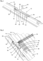
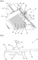
- FIGS 1 to 3 show a covering device 10 for covering a fastening area 12 of a roof 14 with roof tiles 16.
- the roof tiles 16 are suspended from roof battens 18, the roof battens 18 being fastened to roof beams 20.
- a mounting rail 24 for a solar panel or a photovoltaic module can be attached, e.g. clamped, to a roof hook 22 .
- the roof hook 22 can have a base 26 over which the roof hook 22 z. B. attached to the roof beam 20, for example screwed, is.
- the covering device 10 has a metal plate 28 with a cutout 30 for the roof hook 22 .
- the recess 30 is surrounded by a rubber sleeve 32 in which the roof hook 22 is arranged.
- the rubber sleeve 32 can be fastened, for example riveted, to the metal plate 28 via a fastening frame 34 .
- a protective device 36 for the rubber sleeve 32 can be formed on the fastening frame 34 .
- the covering device 10 has a deformable adjustment area 38 .
- the adjustment area 38 can be adjusted to the contour of the roof tile 16 adjoining it. For example, the adjustment area 38 can be pressed on by hand.
- the covering device 10 also has a covering area 40 with corrugations 42 .
- a stabilizing device 44 with folds 46 can be provided on the underside of the metal plate 28 .
- the metal plate 28 can be hung on the roof batten 18 via a front edge 46 .
- the stabilizing device 44 has an opening 48 through which the roof hook 22 is guided.
- the opening 48 can have the same shape as the recess 30 .
- the metal plate 28 can also be bent on three sides.
- the sides are bent upwards in the direction of the rubber sleeve 32 and form a kink 50. This prevents dirt and/or water from penetrating the roof.
Landscapes
- Engineering & Computer Science (AREA)
- Architecture (AREA)
- Civil Engineering (AREA)
- Structural Engineering (AREA)
- Thermal Sciences (AREA)
- Life Sciences & Earth Sciences (AREA)
- Sustainable Development (AREA)
- Sustainable Energy (AREA)
- Physics & Mathematics (AREA)
- Chemical & Material Sciences (AREA)
- Combustion & Propulsion (AREA)
- Mechanical Engineering (AREA)
- General Engineering & Computer Science (AREA)
- Roof Covering Using Slabs Or Stiff Sheets (AREA)
- Seal Device For Vehicle (AREA)
- Glass Compositions (AREA)
Applications Claiming Priority (2)
| Application Number | Priority Date | Filing Date | Title |
|---|---|---|---|
| DE102021100081.5A DE102021100081A1 (de) | 2021-01-05 | 2021-01-05 | Abdeckvorrichtung |
| EP21216131.9A EP4023959B1 (fr) | 2021-01-05 | 2021-12-20 | Dispositif de couverture |
Related Parent Applications (1)
| Application Number | Title | Priority Date | Filing Date |
|---|---|---|---|
| EP21216131.9A Division EP4023959B1 (fr) | 2021-01-05 | 2021-12-20 | Dispositif de couverture |
Publications (2)
| Publication Number | Publication Date |
|---|---|
| EP4236061A2 true EP4236061A2 (fr) | 2023-08-30 |
| EP4236061A3 EP4236061A3 (fr) | 2023-10-25 |
Family
ID=81828052
Family Applications (2)
| Application Number | Title | Priority Date | Filing Date |
|---|---|---|---|
| EP21216131.9A Active EP4023959B1 (fr) | 2021-01-05 | 2021-12-20 | Dispositif de couverture |
| EP23181546.5A Pending EP4236061A3 (fr) | 2021-01-05 | 2021-12-20 | Dispositif de couverture |
Family Applications Before (1)
| Application Number | Title | Priority Date | Filing Date |
|---|---|---|---|
| EP21216131.9A Active EP4023959B1 (fr) | 2021-01-05 | 2021-12-20 | Dispositif de couverture |
Country Status (3)
| Country | Link |
|---|---|
| EP (2) | EP4023959B1 (fr) |
| DE (1) | DE102021100081A1 (fr) |
| ES (1) | ES2951662T3 (fr) |
Families Citing this family (8)
| Publication number | Priority date | Publication date | Assignee | Title |
|---|---|---|---|---|
| DE102022121439A1 (de) * | 2022-08-24 | 2024-02-29 | Sl Rack Gmbh | Abdeckvorrichtung |
| DE202023101486U1 (de) | 2023-03-24 | 2023-05-31 | Aerocompact Group Holding Ag | Befestigungssystem |
| EP4435344A1 (fr) | 2023-03-24 | 2024-09-25 | AEROCOMPACT Group Holding AG | Système de fixation |
| DE202023104047U1 (de) | 2023-07-19 | 2023-08-30 | Zehnder Zimmerei Gmbh & Co Kg | Ersatzdachziegel |
| DE102023119120A1 (de) | 2023-07-19 | 2025-01-23 | Zehnder Zimmerei Gmbh & Co Kg | Ersatzdachziegel |
| DE102024100493A1 (de) * | 2024-01-09 | 2025-07-10 | Matthias Bartholomäus | Universeller Ersatzdachziegel |
| DE102024102720A1 (de) * | 2024-01-31 | 2025-07-31 | Matthias Bartholomäus | Vorrichtung zur Montage eines Befestigungselements |
| EP4756147A1 (fr) * | 2024-12-03 | 2026-06-10 | SL Rack GmbH | Panneau de toiture |
Citations (1)
| Publication number | Priority date | Publication date | Assignee | Title |
|---|---|---|---|---|
| AT13559U1 (de) | 2013-02-22 | 2014-03-15 | Martin Neuwirth | Aufdach-Befestigungsvorrichtung |
Family Cites Families (11)
| Publication number | Priority date | Publication date | Assignee | Title |
|---|---|---|---|---|
| NZ186208A (en) * | 1977-01-17 | 1981-07-13 | G M Cupit | Pipe seal |
| US5053266A (en) * | 1988-12-23 | 1991-10-01 | Dovetail Building Products Limited | Ventilation tile with pliable edge areas |
| DE19518746A1 (de) | 1995-05-22 | 1996-11-28 | Braas Gmbh | Dachelement |
| ITMI20011673A1 (it) | 2001-08-01 | 2003-02-01 | Energo Project Srl | Dispositivo universale per realizzare passaggi su tetti in tegole e coperture in lastre sagomate in genere |
| DE20117618U1 (de) | 2001-10-27 | 2003-03-13 | Klöber GmbH & Co KG, 58256 Ennepetal | Dacheindeckungsplatte oder -matte |
| US7168211B2 (en) | 2003-09-02 | 2007-01-30 | Solatube International, Inc. | Tubular skylight with dome flashing and protective waffle pattern corrugation |
| DE102005041681B4 (de) | 2005-04-23 | 2017-12-28 | Adalbert Sobczynski | Abdeckelement für Gebäudedächer und Gebäudedach |
| WO2009129799A1 (fr) | 2008-04-25 | 2009-10-29 | Viessmann Werke Gmbh & Co. Kg | Système de fixation de toit |
| FR2934618B1 (fr) | 2008-07-31 | 2016-07-01 | Qualitelec | Dispositif de fixation d'element de couverture de toiture |
| DE102011001692A1 (de) | 2011-03-31 | 2012-10-04 | Monier Roofing Components Gmbh | Aus Grundplatte und Abdichtelement zum Durchtritt eines Befestigungselementes aufgebautes Dacheindeckungselement |
| US9394693B2 (en) * | 2013-11-22 | 2016-07-19 | Gregory S. Daniels | Roof vent for supporting a solar panel |
-
2021
- 2021-01-05 DE DE102021100081.5A patent/DE102021100081A1/de active Pending
- 2021-12-20 EP EP21216131.9A patent/EP4023959B1/fr active Active
- 2021-12-20 ES ES21216131T patent/ES2951662T3/es active Active
- 2021-12-20 EP EP23181546.5A patent/EP4236061A3/fr active Pending
Patent Citations (1)
| Publication number | Priority date | Publication date | Assignee | Title |
|---|---|---|---|---|
| AT13559U1 (de) | 2013-02-22 | 2014-03-15 | Martin Neuwirth | Aufdach-Befestigungsvorrichtung |
Also Published As
| Publication number | Publication date |
|---|---|
| EP4236061A3 (fr) | 2023-10-25 |
| ES2951662T3 (es) | 2023-10-24 |
| EP4023959A1 (fr) | 2022-07-06 |
| EP4023959B1 (fr) | 2023-07-12 |
| EP4023959C0 (fr) | 2023-07-12 |
| DE102021100081A1 (de) | 2022-07-07 |
Similar Documents
| Publication | Publication Date | Title |
|---|---|---|
| EP4023959B1 (fr) | Dispositif de couverture | |
| DE202021100034U1 (de) | Abdeckvorrichtung | |
| DE202022104792U1 (de) | Abdeckvorrichtung | |
| DE202009003124U1 (de) | Halterung für Unterkonstruktion von Solarmodulen sowie Unterkonstruktion von Solarmodulen | |
| EP2304124B1 (fr) | Structure de toit | |
| DE69905635T2 (de) | Stützvorrichtung für ein Solarpaneel auf Schrägdächern | |
| DE69513162T2 (de) | Anschlussstreifen für dachelemente | |
| EP2186964B1 (fr) | Recouvrement avec au moins deux tôles métalliques entre des profilés et installation solaire sur ce recouvrement | |
| DE202022002927U1 (de) | Abdeckvorrichtung | |
| DE102009003168A1 (de) | Montagesystem und Verfahren zur Montage von Solarmodulen | |
| EP4328518B1 (fr) | Dispositif de couverture | |
| DE10136037A1 (de) | Dachintegriertes Solarmodulsystem | |
| DE202021004147U1 (de) | Abdeckvorrichtung | |
| DE2839362A1 (de) | Sonnenkollektor | |
| EP2947220A1 (fr) | Agencement de couverture pour une fenêtre de toit d'habitation et toit doté d'une fenêtre de toit intégrée et d'un agencement de couverture | |
| DE9216295U1 (de) | Begrünbare Schrägdachdeckung | |
| EP2770133A1 (fr) | Dispositif de fixation sur toiture | |
| EP3031997A2 (fr) | Systeme de chassis d'ouvertures sur des toits | |
| DE1911899C3 (de) | Firstentlüftung für Kaltdächer | |
| AT525079B1 (de) | Schrägdachaufbau | |
| DE202025101151U1 (de) | Dachplatte | |
| DE102023119120A1 (de) | Ersatzdachziegel | |
| DE1659349C3 (de) | Eindeckrahmen für in der Dachfläche liegende Dachfenster | |
| EP4701070A1 (fr) | Système de fixation pour un élément de construction en forme de panneau sur une construction de toit et module pour toit | |
| DE20313027U1 (de) | Streifenförmige Materialbahn für eine First- und/oder Gratabdeckung |
Legal Events
| Date | Code | Title | Description |
|---|---|---|---|
| PUAI | Public reference made under article 153(3) epc to a published international application that has entered the european phase |
Free format text: ORIGINAL CODE: 0009012 |
|
| STAA | Information on the status of an ep patent application or granted ep patent |
Free format text: STATUS: THE APPLICATION HAS BEEN PUBLISHED |
|
| AC | Divisional application: reference to earlier application |
Ref document number: 4023959 Country of ref document: EP Kind code of ref document: P |
|
| AK | Designated contracting states |
Kind code of ref document: A2 Designated state(s): AL AT BE BG CH CY CZ DE DK EE ES FI FR GB GR HR HU IE IS IT LI LT LU LV MC MK MT NL NO PL PT RO RS SE SI SK SM TR |
|
| REG | Reference to a national code |
Ref country code: DE Ref legal event code: R079 Free format text: PREVIOUS MAIN CLASS: H02S0030000000 Ipc: F24S0025613000 |
|
| PUAL | Search report despatched |
Free format text: ORIGINAL CODE: 0009013 |
|
| AK | Designated contracting states |
Kind code of ref document: A3 Designated state(s): AL AT BE BG CH CY CZ DE DK EE ES FI FR GB GR HR HU IE IS IT LI LT LU LV MC MK MT NL NO PL PT RO RS SE SI SK SM TR |
|
| RIC1 | Information provided on ipc code assigned before grant |
Ipc: E04D 13/147 20060101ALN20230921BHEP Ipc: H02S 30/00 20140101ALI20230921BHEP Ipc: H02S 20/23 20140101ALI20230921BHEP Ipc: F24S 25/613 20180101AFI20230921BHEP |
|
| STAA | Information on the status of an ep patent application or granted ep patent |
Free format text: STATUS: REQUEST FOR EXAMINATION WAS MADE |
|
| 17P | Request for examination filed |
Effective date: 20240328 |
|
| RBV | Designated contracting states (corrected) |
Designated state(s): AL AT BE BG CH CY CZ DE DK EE ES FI FR GB GR HR HU IE IS IT LI LT LU LV MC MK MT NL NO PL PT RO RS SE SI SK SM TR |
|
| STAA | Information on the status of an ep patent application or granted ep patent |
Free format text: STATUS: EXAMINATION IS IN PROGRESS |
|
| 17Q | First examination report despatched |
Effective date: 20241025 |