EP4236132A2 - Séquence binaire pouvant être transmise efficace avec disparité réduite et correction d'erreurs sans voie de retour codée par ligne - Google Patents
Séquence binaire pouvant être transmise efficace avec disparité réduite et correction d'erreurs sans voie de retour codée par ligne Download PDFInfo
- Publication number
- EP4236132A2 EP4236132A2 EP23180790.0A EP23180790A EP4236132A2 EP 4236132 A2 EP4236132 A2 EP 4236132A2 EP 23180790 A EP23180790 A EP 23180790A EP 4236132 A2 EP4236132 A2 EP 4236132A2
- Authority
- EP
- European Patent Office
- Prior art keywords
- bit
- data
- disparity
- segments
- forward error
- Prior art date
- Legal status (The legal status is an assumption and is not a legal conclusion. Google has not performed a legal analysis and makes no representation as to the accuracy of the status listed.)
- Pending
Links
Images






Classifications
-
- H—ELECTRICITY
- H04—ELECTRIC COMMUNICATION TECHNIQUE
- H04L—TRANSMISSION OF DIGITAL INFORMATION, e.g. TELEGRAPHIC COMMUNICATION
- H04L1/00—Arrangements for detecting or preventing errors in the information received
- H04L1/004—Arrangements for detecting or preventing errors in the information received by using forward error control
- H04L1/0041—Arrangements at the transmitter end
- H04L1/0042—Encoding specially adapted to other signal generation operation, e.g. in order to reduce transmit distortions, jitter, or to improve signal shape
-
- H—ELECTRICITY
- H04—ELECTRIC COMMUNICATION TECHNIQUE
- H04L—TRANSMISSION OF DIGITAL INFORMATION, e.g. TELEGRAPHIC COMMUNICATION
- H04L1/00—Arrangements for detecting or preventing errors in the information received
- H04L1/004—Arrangements for detecting or preventing errors in the information received by using forward error control
- H04L1/0041—Arrangements at the transmitter end
-
- H—ELECTRICITY
- H03—ELECTRONIC CIRCUITRY
- H03M—CODING; DECODING; CODE CONVERSION IN GENERAL
- H03M13/00—Coding, decoding or code conversion, for error detection or error correction; Coding theory basic assumptions; Coding bounds; Error probability evaluation methods; Channel models; Simulation or testing of codes
- H03M13/27—Coding, decoding or code conversion, for error detection or error correction; Coding theory basic assumptions; Coding bounds; Error probability evaluation methods; Channel models; Simulation or testing of codes using interleaving techniques
-
- H—ELECTRICITY
- H03—ELECTRONIC CIRCUITRY
- H03M—CODING; DECODING; CODE CONVERSION IN GENERAL
- H03M13/00—Coding, decoding or code conversion, for error detection or error correction; Coding theory basic assumptions; Coding bounds; Error probability evaluation methods; Channel models; Simulation or testing of codes
- H03M13/31—Coding, decoding or code conversion, for error detection or error correction; Coding theory basic assumptions; Coding bounds; Error probability evaluation methods; Channel models; Simulation or testing of codes combining coding for error detection or correction and efficient use of the spectrum
-
- H—ELECTRICITY
- H03—ELECTRONIC CIRCUITRY
- H03M—CODING; DECODING; CODE CONVERSION IN GENERAL
- H03M5/00—Conversion of the form of the representation of individual digits
- H03M5/02—Conversion to or from representation by pulses
- H03M5/04—Conversion to or from representation by pulses the pulses having two levels
- H03M5/14—Code representation, e.g. transition, for a given bit cell depending on the information in one or more adjacent bit cells, e.g. delay modulation code, double density code
- H03M5/145—Conversion to or from block codes or representations thereof
-
- H—ELECTRICITY
- H04—ELECTRIC COMMUNICATION TECHNIQUE
- H04L—TRANSMISSION OF DIGITAL INFORMATION, e.g. TELEGRAPHIC COMMUNICATION
- H04L1/00—Arrangements for detecting or preventing errors in the information received
- H04L1/004—Arrangements for detecting or preventing errors in the information received by using forward error control
- H04L1/0056—Systems characterized by the type of code used
- H04L1/0057—Block codes
-
- H—ELECTRICITY
- H04—ELECTRIC COMMUNICATION TECHNIQUE
- H04L—TRANSMISSION OF DIGITAL INFORMATION, e.g. TELEGRAPHIC COMMUNICATION
- H04L1/00—Arrangements for detecting or preventing errors in the information received
- H04L1/004—Arrangements for detecting or preventing errors in the information received by using forward error control
- H04L1/0056—Systems characterized by the type of code used
- H04L1/0071—Use of interleaving
-
- H—ELECTRICITY
- H04—ELECTRIC COMMUNICATION TECHNIQUE
- H04L—TRANSMISSION OF DIGITAL INFORMATION, e.g. TELEGRAPHIC COMMUNICATION
- H04L25/00—Baseband systems
- H04L25/38—Synchronous or start-stop systems, e.g. for Baudot code
- H04L25/40—Transmitting circuits; Receiving circuits
- H04L25/49—Transmitting circuits; Receiving circuits using code conversion at the transmitter; using predistortion; using insertion of idle bits for obtaining a desired frequency spectrum; using three or more amplitude levels ; Baseband coding techniques specific to data transmission systems
- H04L25/4906—Transmitting circuits; Receiving circuits using code conversion at the transmitter; using predistortion; using insertion of idle bits for obtaining a desired frequency spectrum; using three or more amplitude levels ; Baseband coding techniques specific to data transmission systems using binary codes
- H04L25/4908—Transmitting circuits; Receiving circuits using code conversion at the transmitter; using predistortion; using insertion of idle bits for obtaining a desired frequency spectrum; using three or more amplitude levels ; Baseband coding techniques specific to data transmission systems using binary codes using mBnB codes
Definitions
- the present invention is directed to a method for generating an efficiently transmittable bit sequence with a constrained disparity and a constrained run length.
- the proposed method allows data to be transmitted particularly efficiently via a transmission channel.
- the invention provides the advantage over the prior art, among other things, that despite a reduction in the resource requirements, the physical behavior on a transmission channel can always be controlled deterministically.
- the bit errors are minimal and a transmission error can be corrected efficiently, ie with minimal technical effort.
- the encoders used are designed to be minimal in terms of the number of gates, and an interleaving is implicit in the proposed method, which is based on the fact that so-called burst errors can be corrected in a particularly advantageous manner.
- This implicit interleaving allows the traditional buffers needed for explicit interleaving to be eliminated.
- user data together with correcting metadata can be advantageously encoded with regard to the transmission.
- An optimized disparity represents a quality feature for the transferability of data.
- a disadvantageous disparity can result in data not being able to be properly transmitted via a data channel, since it cannot be properly interpreted by the receiver.
- Another quality feature is the data efficiency with regard to the ratio of transmitted user data and an additional amount of data that does not relate directly to the user data in terms of content. This includes so-called header data.
- the proposed invention makes it possible to generate data streams that can be read particularly efficiently and are also very efficient with regard to the excess data. In this way, the so-called overhead of the user data is minimized, which in turn creates a particularly efficient method.
- the clear interpretability on the receiver side also ensures that data does not have to be transmitted repeatedly, but can be read out on the receiver side with a high level of error security.
- the proposed method is particularly efficient since a transfer of data segments into partial symbols or into symbols composed of partial symbols can be carried out in parallel, and this parallel execution only requires units that are technically easy to produce.
- the Efficiency gain also on the hardware or runtime to be used.
- the invention is also aimed at a correspondingly set up system arrangement and at a computer program product and a memory-readable medium with control commands that execute the method.
- EP 3323219 A1 shows a method that makes it possible to read an analog data stream via a data line in a particularly error-proof manner.
- the amplitude of the signal is monitored and the signal is particularly preferably measured at that point at which the amplitude is maximum. This converts an analogue data stream into a digital data set and the maximum amplitude ensures that the threshold value between 0 and 1 on the line is safely undercut or exceeded.
- FEC Forward Error Correction
- GbE 10 Gigabit Ethernet
- prior art relates to the transmission of data in a serial data stream.
- the prior art provides, for example, that extensive description data are sent with the user data, which indicate where the user data is located or how it is to be interpreted.
- it is known in the prior art to discard individual data packets if they are not properly transmitted.
- it is known in the prior art to resend data packets if they do not arrive at a sender in time or in an unexpected format.
- the disparity In the serial transmission of data, it is necessary to have the number of ones and zeros in the serial data stream as equal as possible. This is called the disparity. A disparity of zero on average and over a short period of time is desirable so that a so-called baseline drift does not occur during transmission. The baseline drift (DC voltage fluctuation) of the serial signal leads to bit errors. In extreme cases, transmission is not possible.
- the task of the line code (in this case a block code) is to generate a symbol with guaranteed disparity and guaranteed run length from any data words with any disparity and infinite run length. This introduces an overhead in the Transmission. It is therefore necessary to transmit more bits (in the form of symbols) than occur in the data word to be transmitted net. This means that the required transmission speed (bandwidth) must be greater than the data rate of the data to be transmitted. This in turn leads to systems requiring higher error rates or more effort, power, etc. than would be necessary to transmit the raw data.
- the prior art either has a high overhead (8B10B) or the quality of the coded signal in terms of disparity and run length is very poor, so that additional measures (complexity) such as scramblers are often necessary to improve the quality in the event of disparity or run length .
- a method for generating an efficiently transmittable bit sequence with a limited disparity, a limited run length and a line-coded forward error correction, comprising providing any bit sequence; a segmentation of the provided bit sequence into a predefined sequence of segments according to a respectively predefined bit length; calculating a forward error correction for each of the segments or a plurality of segments of the same bit length; coding each segment or a large number of segments with the same bit position together with its/their forward error correction in one or more sub-symbols, using the same coding unit for the segments with the same bit position and the associated forward error correction from one Plurality of coding units, wherein a first subset of coding units actively controls a sign of the disparity of the sub-symbol by inverting the disparity of the generated sub-symbol to compensate for a disparity of a second subset of coding units, wherein lining up the sub-symbols results in the efficiently transmittable bit sequence together with the
- a potentially infinitely lasting bit stream which has any bit sequence.
- the data stream can be of any length and can in turn be divided into words or any desired bit sequence.
- An output data stream is thus provided which has a bit sequence which is potentially of any length.
- this arbitrary length can be defined in a preparatory method step and can preferably be defined as 112 bits.
- any length of the bit sequence cannot be understood as arbitrary within the meaning of the present invention. Rather, a bit sequence can be provided as a synonym of the arbitrary bit sequence according to the invention, the length of which can be freely selected in advance and/or the content of which corresponds to the data to be transmitted or at least part of the data to be transmitted.
- the output data stream or the output bit sequence can have so many bits that the method is carried out iteratively in such a way that any number of bit sequences are generated from the output bit sequence, segmented, converted into sub-symbols, optimized with regard to disparity and then transmitted.
- the output bit sequence can therefore also be of any length and can ultimately be transmitted in a number of overall symbols.
- coding units there are a plurality of coding units, one coding unit being assigned to each segment, which in turn corresponds to a part of the bit sequence that is arbitrary or freely selectable in advance. This then converts the segment into a sub-symbol, with the set of sub-symbols concatenating the symbol or the overall symbol corresponds to the bit sequence to be transmitted efficiently.
- a coding unit in a logical path of the processing chain or the structural arrangement between a segment and a partial symbol.
- the proposed method is particularly efficient since the transmittable bit sequence has a particularly high level of useful data compared to the prior art. For example, it is possible to transmit 128 bits, which have 112 bits of user data. Thus, the proposed method is already superior to the prior art in this aspect.
- the generation of the transmittable bit sequence is particularly efficient, since this can be done in parallel and coding units can be used for this purpose that are of particularly simple design. In this context, simple means, for example, that very few circuits have to be installed in the coding units.
- the coding units do not have to have extensive logic and can even be optimized for a specific number of bits. It is thus possible according to the invention for the input and the output of the respective coding unit to be fixed in terms of the number of bits.
- the efficiency therefore also refers to the fact that the bit sequence is particularly robust against errors and can therefore be reliably transmitted only once. A redundant transmission is avoided due to the high detectability, in turn due to the optimized disparity.
- the proposed method can also be referred to as a method for efficiently encoding a bit sequence.
- the disparity is optimized by skilfully adjusting partial disparities. This can be used particularly advantageously when the run length of the bit sequence is limited.
- the constrained disparity and the constrained run length can also relate to the provided arbitrary bit sequence. Thus, it does not have to be the bit sequence that can be efficiently transmitted. Overall, any bit sequence that is provided can be transmitted efficiently, or a bit sequence to be transmitted is generated or produced from this bit sequence, which can then be transmitted efficiently.
- any desired bit sequence that encodes user data is provided. Problems can occur in this arbitrary bit sequence, which consist, for example, in the fact that there is an unfavorable disparity. Too many zeros can cause problems when transferring. This is to be avoided and the arbitrary bit sequence is thus optimized in further method steps in such a way that it can now be transmitted efficiently.
- the provided random bit sequence thus represents any user data that is to be sent from a transmitter to a receiver via a serial data channel.
- the arbitrary bit sequence can be control data in an automobile, for example.
- the bit sequence provided is segmented into a previously defined sequence of segments according to a respectively previously defined bit length.
- the input data stream i.e. any bit sequence
- the input data stream is thus divided according to a predefined method, so that individual data segments are created.
- the segments thus cumulatively result in any bit sequence.
- the previously defined bit length has the advantage that coding units can be optimized in the same way that the respective bit length is taken into account. Particularly efficient circuits that are highly specialized can thus be created. Defined bit lengths are mentioned below, but these are only examples.
- Each segment is coded into a partial symbol using one coding unit per segment from a plurality of coding units.
- the coding itself takes place in a coding unit, which in each case finds a segment at the input and then converts this segment into a partial symbol.
- the sub-symbol is also a bit sequence.
- the arbitrary bit sequence is divided into segments, these segments are each converted into a partial symbol by a coding unit, and the entirety of the partial symbols results in the coding of the arbitrary bit sequence to be transmitted.
- it is advantageous that the number of segments corresponds to the number of coding units and thus to the number of sub-symbols.
- each segment finds exactly one coding unit, which in turn generates exactly one sub-symbol from the segment.
- the plurality of coding units describes all coding units to be used, which corresponds to the number of segments.
- the number of segments is predefined, since a previously defined bit length is specified. The method is therefore deterministic overall.
- a first subset of coding units which actively controls a sign of the disparity of the sub-symbol by inverting the disparity of the sub-symbol generated to compensate for a disparity of a second subset of coding units.
- coding units of the first subset can be referred to as active and coding units of the second subset as passive.
- the different subsets or types of coding units make it possible to connect the coding units in series in such a way that coding units of the first subset also advantageously shape the total disparity of the partial symbols from the coding units of the second subset.
- coding units are used which are arbitrary with regard to the disparity of the sub-symbol.
- a coding unit of the first subset can then be connected in parallel, which controls the sign of the disparity of the preceding coding unit and its own coding unit or their partial symbols depending on the disparity of the coding unit of the second subset.
- a certain number of coding units of the second subset is used and then a further certain number of coding units of the first subset is used.
- the types or subsets of the coding units change in such a way that the respective next coding unit connected in parallel adapts the disparity of the preceding partial symbol(s) and/or its own partial symbol.
- coding units of the first subset optimize coding units of the second subset with regard to disparity.
- Optimizing a disparity means that the disparity is 0. How the person skilled in the art calculates disparities or adjusts them, for example by changing the sign, is the well known to those skilled in the art.
- sub-symbols are thus created which are optimized in their sequence with regard to disparity. Since each segment is converted into a sub-symbol, the (overall) symbol to be transmitted can be generated by lining up the sub-symbols. This can be transmitted in a particularly efficient and fault-tolerant manner, since the disparity or the partial disparities are optimized. A particularly advantageous bit sequence to be transmitted results in this way.
- the arbitrary bit sequence is unrestricted in its disparity and run length. This has the advantage that any desired amount of user data can be transmitted or can be converted into a bit sequence which is limited in terms of disparity and length. Thus, any bit sequence is encoded into a bit sequence to be transmitted, which is optimized in terms of its disparity and run length.
- the disparity of the second subset of coding units is not controllable. This has the advantage that any partial symbol can be generated using the coding units of the second subset, with particularly simple coding units having to be used. These can be configured in a particularly simple manner since the sub-symbol generated by this coding unit is not subject to any restrictions with regard to disparity or run length.
- the sign is actively controlled in each case by conditionally inverting the sub-symbol.
- This has the advantage that the corresponding sub-symbol of the coding units of the first subset can be controlled in a simple manner. Only the disparity or individual bits of the sub-symbol have to be inverted.
- the sign refers to the disparity of the sub-symbol, which can be positive or negative.
- the conditional inversion takes place depending on the disparity of an overall symbol, which is formed from all sub-symbols.
- the dependency is influenced in such a way that an absolute value of the disparity is minimized.
- This has the advantage that the lowest possible disparity, preferably 0, is achieved. Disparities are thus linked with one another in such a way that the amount of the disparities is as low as possible or as low as possible.
- the absolute value is minimized in such a way that, given a positive overall symbol, disparity is counteracted by a negative parity of the partial symbols. This has the advantage that the positive overall symbol disparity is minimized or eliminated.
- the absolute value is minimized in such a way that, given a negative overall symbol, disparity is counteracted by a positive parity of the partial symbols. This has the advantage that the overall symbol disparity is minimized or eliminated overall.
- the active control takes place as a function of total symbols that have already been transmitted, such that the disparity of all total symbols is minimized.
- coding units of the first subset encode segments of 11 bits onto sub-symbols of 13 bits.
- This has the advantage that 11 bits are encoded particularly efficiently and this only results in an additional outlay of 2 bits. This is particularly advantageous when an overall symbol of 128 bits is to be created.
- the present specific values of the proposed technical teaching were determined empirically and can be proven by the fact that only an additional outlay of 128-112 bits, ie 14%, is necessary. The values listed here are therefore proven to be advantageous when 112 bits are transmitted.
- coding units of the first subset have a disparity between +3 and +9, which are intentionally inverted to -3 to -9 by inversion.
- This has the advantage that, for example, a disparity of +3 is canceled with a disparity of -3, which is analogous to a disparity adjustment of +9 with a disparity of -9.
- This is in turn particularly advantageous in the case of an arbitrary bit sequence of 112 bits which is to be encoded as 128 bits.
- the run length in sub-symbols is a maximum of 7. This has the advantage that a maximum of 7 identical instances of zeros and ones are generated, which is particularly advantageous in the proposed scenario of 112 bits and 128 bits, respectively.
- the run length of the sub-symbol in coding units of the first subset, starting from the most significant and/or the least significant bit is a maximum of 5. This has the advantage that a maximum of 5 identical bits can be present at the end or at the beginning of a sub-symbol. This has also proven to be particularly advantageous in the scenario described.
- 11 bit segments are encoded onto 12 bit sub-symbols or 7 bit segments onto 8 bit sub-symbols or 6 bit segments onto 8 bit sub-symbols.
- a disparity between -2 and +2 is generated in coding units of the second subset. This has the advantage that, in turn, particularly advantageous disparities are generated.
- the run length in the generated sub-symbol is 6. This has the advantage that particularly optimized sub-symbols are again generated.
- coding units of the second subset generate sub-symbols which have a maximum run length of 3 at the edge. This has the advantage that sub-symbols that are created by the second subset of coding units have a run length of at most 3 at the beginning or at the end, which is a particularly advantageous value.
- the coding units are addressed in parallel and a segment is coded into a partial symbol in each case.
- This has the advantage that a segment is converted into exactly one sub-symbol with exactly one coding unit.
- the coding units can thus be addressed in parallel, since segments are formed from the arbitrary bit sequence, which can be converted into partial symbols in parallel.
- the coding units are addressed in the order 21212221212, with a 1 standing for a coding unit of the first subset and a 2 for a coding unit of the second subset.
- a multiplexer selects that data stream that contributes to minimizing the overall disparity of the overall symbol.
- the suitable data stream can be selected which has a sign which minimizes or eliminates the disparity. For example, if the disparity to be optimized is negative, a data stream with a positive disparity is selected, which then minimizes or evens out this data stream with regard to its disparity.
- the forward error correction is improved in that it is calculated with reference to user data and the user data is first segmented for this purpose. A separate forward error correction is then calculated for each segment, so that the forward error correction does not relate to an entire data word, but to different subwords.
- the number of gates of the FEC coder to be used is kept low and an exponential growth is avoided.
- an improvement results from the fact that, according to the invention, line coding takes place via the user data together with the forward error correction, and the disadvantage of the prior art that the forward error correction is transmitted in a non-coded form is thus overcome.
- the error correction can work more efficiently, since the error correction only relates to subwords and it is therefore possible to identify in a finely granular manner where an error has occurred.
- Conventional error corrections always refer to entire data words and are therefore inefficient or errors can occur in the prior art that cannot be corrected. According to the invention, this is avoided by the segmentation.
- a further improvement is that all transmitted data is line coded and thus the entirety of the data can benefit from line coding.
- the transmission link can thus be controlled deterministically and the bit errors are kept to a minimum.
- implicit interleaving results from sending smaller packets and thus implicit interleaving since not all of the data words are transmitted. This is achieved by using several forward error correction coders, each of which only relates to subwords.
- the disadvantage in the prior art is overcome that an explicit nesting has to be created in a complex manner, which would also require further buffer memories.
- the efficiency therefore also refers to the fact that the bit sequence is particularly robust against errors and can therefore be reliably transmitted only once. A redundant transmission is avoided due to the high detectability, in turn due to the optimized disparity.
- the proposed method can also be referred to as a method for efficiently encoding a bit sequence.
- the disparity is optimized by skilfully adjusting partial disparities. This can be used particularly advantageously when the run length of the bit sequence is limited.
- the constrained disparity and the constrained run length can also relate to the provided arbitrary bit sequence. Thus, it does not have to be the bit sequence that can be efficiently transmitted. Overall, any bit sequence that is provided can be transmitted efficiently, or a bit sequence to be transmitted is generated or produced from this bit sequence, which can then be transmitted efficiently.
- the proposed method can be used specifically in the vehicle or specifically tailored to the needs of the vehicle. This is the case because safety-critical functions are offered in the vehicle, which must be protected accordingly. According to the invention, this takes place in several ways. On the one hand through the forward error correction and via the line coding. In addition, the reduced number of required gates has an advantageous effect, especially in electromobility.
- user data to be transmitted is provided in a preparatory method step.
- This is typically a bit sequence of a fixed length. This can also be referred to as a data word.
- the user data provided is then divided into a plurality of bit sequences, each of the same length.
- these bit sequences can have a length of 112 bits.
- the user data can be a continuous data stream, the bit sequences are always of a certain length and in a certain way provide a subdivision of the user data.
- a bit sequence is also referred to below as a data word.
- the bit sequences are arranged one below the other. Thus, each individual bit sequence extends horizontally and the individual bit sequences are arranged vertically one below the other.
- a subdivision rule is read out, which subdivides a bit sequence into a sequence of segments, each of a predefined length at a predefined position.
- the subdivision rule can be in the form of a data format that defines how long a segment must be. In this case, the individual segments do not have to be of the same length, but this can vary from segment to segment.
- the subdivision rule stipulates that the individual bit sequences each have the same format, so that, figuratively speaking, the same vertical subdivisions result. For example, a first segment of each bit sequence can have 11 bits. For example, the first four segments can each have 11 bits, which is followed by a segment of 7 bits. A segment with 11 bits can then be provided again and then a segment with 6 bits.
- This data format is maintained for all bit sequences.
- the segments in the same position can always be of the same length, with the segments being able to differ vertically, figuratively speaking.
- the segments, figuratively speaking, per line then form the bit sequence.
- the bit sequences in their vertical arrangement form the user data in their entirety.
- the subdivision rule that has been read out is applied to all bit sequences of the plurality of bit sequences until the entire useful data has been broken down horizontally into bit sequences and the segments have been formed vertically.
- all bit sequences are subdivided according to the same subdivision rule.
- the subdivision rule can be read from a data memory and applies to all bit sequences that have been obtained from the user data.
- the user data it is also possible for the user data to be merely divided into a bit sequence or for the user data to already be present in length as a bit sequence. Thus, a partial forward error correction is then generated for each segment.
- a segment coder is then used iteratively over all segments in the same bit position in order to generate segment line codes over all segments for each bit position and for each bit sequence.
- line encoders are provided specifically for predetermined lengths. This ensures that the vertical segments can each be coded by a single line coding.
- the iterative application of the segment coders thus ensures that, figuratively speaking, the segments are line-coded column by column, and this takes place across all segments until all bit sequences are line-coded with respect to their segments.
- the partial forward error correction has the same number as the respective segments.
- the partial forward error correction can be encoded using the same line encoder as the corresponding segments.
- Partial forward error correction which was also applied to the segments with respect to which the respective partial forward error correction was created in order to generate one partial forward error correction line code per partial forward error correction. Consequently, those segment encoders are used which have line-coded the respective segments and then also line-code the respective partial forward error corrections. Thus, the segments are line-coded column by column with the same segment coder as the partial forward error corrections that relate to the respective column.
- the subdivision rule is stored in a data memory and is available as a coding rule and/or is read from a hardware architecture.
- This has the advantage that the subdivision specification can be statically specified or can also be changed in the data memory.
- the subdivision rule can take into account the corresponding hardware architecture. If, for example, different coders are available for different bit lengths, the bit sequences can be subdivided in such a way that the corresponding segments correspond to the respective coders. The segments therefore have exactly the length specified by the respective coder.
- all bit sequences have the same structure in their data format, have the same segment lengths and/or the same bit positions.
- This has the advantage that the individual segments can be fed to the respective coders. For example, every first segment of each bit sequence is fed to the same encoder.
- the segments can be coded column by column and there is a specialized coder for each column.
- the partial forward error correction has correction information which describes a target content of the segment via which the partial forward error correction was created.
- the partial forward error correction has the same bit length as the segment over which it is created.
- This has the advantage that specialized line coders can be kept available and maximum efficiency is thus created in that the corresponding column-by-column line coders are specialized precisely for the bit length that they then also have to code. This creates an efficient and technically minimally complex process.
- a total of the partial forward error corrections describe all user data to be transmitted in a correctable manner. This has the advantage that all user data that is transmitted can be corrected for its errors, but can be tailored to the individual segments, so that the proposed method is more fine-grained than the prior art provides.
- the segment encoders each generate at least part of a line code. This has the advantage that the outputs from the segment coders can be combined and then provide the line codes to be transmitted.
- all of the segment encoders encode bit sequences of 112 bits into words of 128 bits. This has the advantage that a particularly efficient line code or line code is created.
- the partial forward error correction line codes are appended to the segment line codes when transmitting. This has the advantage that all of the data to be transmitted is line-coded and the line is therefore operated deterministically, or the advantages of line coding can be used for all data and not just for the user data itself.
- bit position is specified as an offset or as a bit index in the bit sequence.
- the user data is present as a serial data stream. This has the advantage that theoretically any amount of user data can be transmitted, which is then divided into bit sequences of the same length.
- the method steps are carried out in the order described and/or carried out iteratively.
- This has the advantage that the order of coding is reversed.
- the forward error correction is created first and then the line coding takes place. This does not rule out that individual process steps have to be carried out several times. This can be the case, for example, when there are several bit sequences and these have to be segmented.
- a line code segment is generated for each data subword block and/or each data subword block forward error correction. This has the advantage that the forward error correction in particular does not have to be transmitted uncoded, but rather it is also line-coded. Thus, the advantages of line coding are not only available for the user data but also for the forward error correction.
- a forward error correction for a data block is composed of a plurality of partial forward error corrections of the data subword blocks.
- the data structure is read out and a forward error correction coder is selected depending on the respective bit lengths of the data subwords.
- a forward error correction coder is selected depending on the respective bit lengths of the data subwords.
- the number of gates of the FEC part coders is selected as a function of a bit length of the data part words.
- the number of all gates of all encoders is selected in such a way that when the method is executed iteratively, there is a linear increase in the number of gates with regard to increasing data word lengths.
- This has the advantage that, taking into account the data format, a minimum number of gates is provided or that the data format can already be selected in such a way that only a linear increase in the number of gates is necessary.
- the maximum bit length can be 10, 11 or 12 bits, which means that the required gates or circuits of the FEC coder only increase linearly. Since an exponential growth in gates is necessary for larger values, the present invention creates the technical effect that the power consumption or the energy consumption is minimized, which in turn leads to less waste heat.
- the proposed method is particularly robust, which is particularly advantageous in automobiles, since safety-critical functions are offered here.
- each data word has 112 bits. This has the advantage that, with line coding, words of 128 bits can be created, which corresponds to a common format. According to the invention, it was shown that just 112 bits, particularly errors, can be coded robustly with 128 bits. This ensures that the transmission is subject to a lossy or error-prone data channel.
- the bit length of the Data subword block forward error correction chosen to match the bit length of the data subwords.
- the present invention thus makes the technical contribution that not only is a minimum number of gates to be kept available, but rather the number of encoders is also minimized overall. In this way, the forward error correction can be line-coded with the same coder as the actual segments of the payload data.
- the data subword block forward error correction and the data subword block on the basis of which the data subword block forward error correction is calculated are line-coded by means of the same line encoder. This has the advantage that a minimum number of line codings has to be kept available. Figuratively speaking, almost all columns, i.e. all sub-word blocks together with the corresponding partial forward error correction, are line-coded with the same segment coder.
- the data structure is selected as a function of the bit length of the data words. This has the advantage that the different bit lengths can also be addressed dynamically at runtime and the same data format can thus be selected for further data words as for a first data word provided. If the first data words are present, a corresponding data structure can be used in a further serial data stream and the further data words are structured in such a way that they correspond to the data structures of the data words received first.
- serial line encoding is performed after computing the data subword block forward error correction. This has the advantage that the order provided in the prior art is reversed and the forward error correction is calculated first, which means that this can also be line-coded and does not have to be transmitted unencrypted or uncoded.
- the method steps are performed in virtualized form and information about the underlying encoders and/or gates is generated.
- This has the advantage that in a preparatory step Executions can be evaluated and in this respect it can be determined how many gates or how many FEC coders and/or line coders are to be kept available.
- the process can be simulated as a whole. Hardware components can be provided virtually.
- One aspect of the present invention is to bundle multiple data streams (video, audio and data) into a transport frame and transmit them serially.
- the different data formats not only have different bandwidth requirements, but also different latency, reassembly sublayer and bit error rate requirements.
- the transmission of today's video data formats not only requires the transmission of the pure video data and its frame information, but also the support of encryption methods such as HDCP. All of this requires many different data channels with the most varied requirements in terms of bandwidth, latency, reassembly sublayer, etc.
- the technology follows the basic idea of bundling the services very consistently, but offers completely new possibilities with regard to network architectures and allows new approaches in the implementation of today's video interfaces.
- it can be used as a universal data transport layer, for example to transmit Ethernet or camera data or any type of sensor data.
- Virtual paths also have the advantage that they can be used as multiplexing offshoots for different services (video, audio, Ethernet), since the properties of the virtual paths can be configured differently without the different virtual paths interfering with each other.
- Virtual paths only consume bandwidth when data is actually being transmitted.
- a virtual path layer is provided between the physical layer (serializer and framer) and the various application data interfaces.
- Another part of the virtual path layer is an application adaptation layer that performs the conversion of video (stream) or e.g., Ethernet (packet) data into the cells.
- This application customization layer also includes the OAM functions for network diagnostics and management.
- the technology can be the basis for the transmission of a variety of data formats over a serial connection in the car (and elsewhere). It thus forms the basis for a new generation of devices.
- the virtual path layer is, according to one aspect of the present invention, the physical layer, which consists of the transmission sublayer and the physical medium sublayer, the cell layer and the application adaptation layer, the segmentation and reassembly sublayer and the functions for adapting the data formats to the appropriate application contains.
- the main task is to create the physical connection to other physical layers.
- This connection is basically to be understood as bidirectional. Theoretically, this connection can be realized via a wide variety of media. In practice, two serial differential GBps links are used. The line coding, the insertion of idle cells to decouple the cell rate from the connection rate and the integration of the cell stream into the serial frame take place in this layer.
- the segmented data (cell payload) of the overlying Segmentation & Reassembly sub-layer is assembled into complete cells with header, VP identifier and CRC, or cells are CRC-checked and the payload is sent to the Segmentation & Reassembly sub-layer passed on.
- the multiplexing of the different cell streams of the application adaptation functions or the distribution of the cell payloads to the application adaptation functions according to the VP identifier also takes place here. (feed in / feed out)
- the multiplexing and demultiplexing of cell streams in repeaters and splitters also takes place in the cell layer.
- the task of the application adaptation functions is to adapt the data of the application interfaces to the format of the payload data field of the cell and to transmit control information to the other end or to use control information from the other end for the adaptation (time generation, framing).
- all virtual data paths are unidirectional, i.e., they begin with an initiator and end with one or more targets. If virtual data paths logically belong together, e.g. HDCP for a video channel, and thus form a bi-directional data path, these paths should have the same VP identifiers.
- the Stream Data function combines time-domain traversal and bit-wide conversion of data from the application interface to the N-bits of the cell rows.
- the cell row payload is already pre-formatted so that the cell footer and header fit in the first and last cell row.
- Streamed data is (usually) source synchronous.
- time domain crossing clock domain crossing
- the time domain crossing of the data path from the application time domain to the time layer domain (application clock domain to the Virtual Path Layer clock domain) is performed.
- a data buffer is provided in the transmission direction, into which the source-synchronous data are written with the source clock.
- the segmentation layer retrieves the data from this buffer as needed to perform the data format conversion into the N-bit rows of cells.
- Frame data e.g.: Hsync, Vsync, DE
- payload info bits so that the frame can be reconstructed on the receiver side.
- the cell data is written from the reassembly sublayer into a data buffer with cell row bit width.
- the frame information is reconstructed based on the payload info bits.
- the source clock is regenerated using, for example, buffer fullness and clock synthesis.
- HDCP data encryption
- the interface to the segmentation & reassembly sublayer is the same for all functions.
- the burst data function combines time domain crossing and data bit wide conversion of data from the application interface to the N bits of the cell rows.
- the cell line payload is already preformatted so that the cell footer and header fit in the first and last cell line.
- Burst data is (usually) synchronous to an external time and has different identification signals for direction and data type (address/data/byteenable).
- This data is usually accompanied by control lines to implement a specific protocol.
- a data buffer is provided in the transmission direction, into which the burst data is written with the interface clock.
- the segmentation layer retrieves the data from this buffer as needed to perform the data format conversion into the N-bit rows of cells.
- the cell data is written into a data buffer by the reassembly sublayer, with the row of cells being bit wide.
- the interface control signals are reconstructed based on the payload info bits.
- the payload info bits are used to generate the control signals of the application specific interfaces or to synchronize the protocol state machines in the application specific interfaces.
- SPIBurst SPIBurst, I2CBurst, MIIBurst.
- a system arrangement in an automobile for generating an efficiently transmittable bit sequence with a limited disparity and a limited run length having an interface unit set up to provide any bit sequence; a segmentation unit set up for segmenting the provided bit sequence into a predefined sequence of segments according to a respectively predefined bit length; a calculation unit configured to calculate a forward error correction for each of the segments or a plurality of segments of the same bit length; a coding arrangement set up for coding each segment or a large number of segments with the same bit position together with its/their forward error correction into one or more sub-symbols, using the same coding unit for the segments with the same bit position and the associated forward error correction from a plurality of coding units, with a first subset of coding units actively controls a sign of the disparity of the partial symbol by inverting the disparity of the generated partial symbol to compensate for a disparity of a second subset of coding units, with lining up the partial symbols yielding the efficiently transmittable bit sequence together with the
- the object is also achieved by a computer program product with control commands that implement the proposed method or operate the proposed device.
- the method can be used to operate the proposed devices and units.
- the proposed devices and facilities are suitable for carrying out the method according to the invention.
- the device implements structural features which are suitable for carrying out the corresponding method.
- the structural features can also be designed as method steps.
- the proposed method also provides steps for implementing the function of the structural features.
- physical components can also be provided virtually or virtualized.
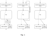
- FIG. 13 shows three exemplary embodiments of how forward error correction is performed according to conventional methods.
- An exemplary embodiment is shown on the left-hand side, which first carries out a serial coding of the user data and then generates a forward error correction code FEC.
- the serially encoded data is transmitted and subsequently the forward error correction is encoded and then appended to the encoded user data.
- the forward error correction is generated over a complete data word and this must then be encoded again and is appended. It is therefore not encoded via the individual segments, but via the bit sequence as a whole.
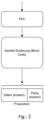
- figure 2 shows the method according to the invention in which forward error corrections are generated via the user data and these are then likewise encoded with the user data.
- the advantage here is that both the user data and the forward error correction are line-coded and errors are therefore robust.
- This figure also shows that the difference from the prior art is that the forward error correction is generated directly on the user data and not on the line-coded user data. This then enables all data to be transmitted in line-coded form, which in turn results in increased error robustness.
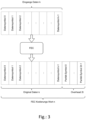
- FIG 3 Figure 12 shows a prior art flow chart wherein the input data is line encoded and then forward error correction is generated. This forward error correction is appended to the present right-hand side, as shown at the very bottom.
- the data word above is line-coded first and then a non-line-coded forward error correction is appended.
- the data is not DC (digital current) balanced, ie an advantageous parity is not set.
- line coding is advantageous in that a mean value of those analog signals can be measured and it can then be checked which actual signals are above this mean value and which are below it. It is desirable here that the number of analog signals above the mean value, ie digital "1", is equal to the number of analog signals below the mean value, ie digital "0". Thus, an optimized signal modeling can be carried out. This is in the present figure 3 not possible because the forward error correction code is not line coded.
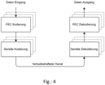
- FIG 4 shows the procedure according to the invention and the transmission via a lossy channel.
- each channel is potentially lossy and it is particularly advantageous that the forward error coding takes place at the data input first and then the entire serial coding takes place.
- the procedure is carried out analogously inversely and a serial decoding is carried out first, whereby the forward error correction is restored in addition to the useful data.
- figure 5 shows a method according to the prior art in an upper exemplary embodiment, with an output data word or a bit sequence being line-coded from the first to the second line in a first method step.
- a forward error correction code is generated from the second line to the third line, which code is added to the line coding.
- the first part on the left of the data to be transmitted is line-coded and the second part, namely the forward error correction, is not line-coded. This poses problems because the benefits of line coding are sacrificed in the appendix on the right. This is disadvantageous.
- the starting word ABC is again drawn in at the top.
- the bit sequence therefore consists of the segments A, B and C. In the present case, these are 11 bits, 6 bits and 7 bits long. According to the invention, it is not the entire data word, i.e. the entire bit sequence, that is protected in its entirety, i.e. provided with a forward error correction code, but the individual segments are protected. This is indicated in the second line by the corresponding forward error correction code being indicated after each segment A, B and C.
- line coding is applied in the third line, or the data from the second line are completely line-coded, which leads to a line code in the third line. This can now be transmitted and it can be seen that all of the data is line-coded and that the forward error correction code is also line-coded.
- the advantages of line coding apply to all data to be transmitted.
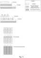
- bit sequences are drawn in, with the useful data now being divided into bit sequences of the same length.
- the entirety of the user data is thus subdivided into four bit sequences in the present case, which are all of the same length.
- This present four bit sequences again divided into segments of equal length.
- individual bit sequences are therefore arranged horizontally and these bit sequences are arranged figuratively one below the other, so that each line reflects a bit sequence.
- the bit sequences are each divided into three segments of equal length. This gives a matrix-like arrangement of the user data in bit sequences per row and segments per column.
- a segment coder is now used over all segments in the same bit position to generate segment line codes over all segments for each bit position and for each bit sequence.
- that segment coder that was also used for the segments is applied to the respective partial forward error correction, resulting in a single line code that includes the segment line codes and the partial forward error correction line codes.
- all data was line-coded and, in particular, the forward error correction FEC was also line-coded. This data can thus now be advantageously transmitted.
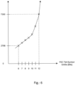
- figure 6 shows in a diagram on the y-axis the number of gates required when creating a forward error correction code as a function of the bit length to be coded on the x-axis.
- this is an exponential growth and from a bit length of 10-12 bits, the growth of the gates, ie the number of gates required for the forward error corrections, increases above average. It is therefore particularly advantageous according to the invention to carry out the forward error correction for each segment, since this avoids having to take the entire data word, ie the entire bit length, into account. If the entire bit length had to be taken into account in the forward error correction, then the bit length would be typical beyond the critical 12 bits. The required gates in the forward error correction encoder would increase disadvantageously. This thus illustrates the advantageous technical effect of the present invention, which first forms segments over the bit sequence and then calculates the forward error correction on the segments.
- the same symbol widths do not always have to be used here for the respective small FEC sub-coders.
- Large serial codings can also consist of several different sub-codings (simplest example 8b10b which can be built up from 3b4b and 5b6b), as suggested with the use for FEC. In the case of the present invention or ADXpress (registered trademark), this is achieved by a total of 11 encoders with four basic types: 6b8b, 7b8b, 11 b12b and 11 b13b.
- the FEC symbol width used for the respective sub-coding results from the data word width of the respective serial coder. For e.g. 6b8b, an FEC with a symbol width of 6 bits is used accordingly.
- the complete structure for the transmitter data path of the present invention or ADXpress (registered trademark) is, according to one aspect, in Figure 8A shown.
- the data path in the receiver is structured inversely (see also Figure 8B ).
- Figure 7A shows a line coding or a line coding device with a plurality of line coding units which, for example, map 11 bits to 12 bits, map 11 bits to 13 bits, or map 11 bits to 12 bits. This corresponds to the order in which present figure 7 right to left and makes it clear that the input data word, i.e. the bit sequence above, is divided into individual segments and then the individual segments are line-coded.
- the forward error correction calculation is in the present Figure 7A not yet taken into account, so the system arrangement according to Figure 7A can serve as the starting system arrangement for the present invention.
- Figure 7A shows above the arbitrary bit sequence of 112 bits, which is segmented into 11, 6 or 7 bits.
- the coding units are then addressed in parallel, which convert the bits into sub-symbols in such a way that they are optimized in terms of disparity. For example, 11 bits are encoded after 12 bits, or 11 bits after 13 bits.
- a coding unit from the second subset is drawn in on the far left in the middle, which bears the designation 11 B12B.
- the encoded unit 11B13B is connected in parallel with respect to the bit sequence. i.e. i.e. that a data stream is formed that converts the most significant bits of two times 11 into two sub-symbols, namely once the 11-bit data segment is formed into a 12-bit sub-symbol with any sign, i.e. disparity, and once the data segment of 11 Bit encoded into 13 bits by means of the coding unit 11 B13B.
- the second coding unit from the left 11B13B is a coding unit of the first subset.
- This has an inverter and a multiplexer.
- the first 13 bits are therefore available as a data stream, which is split up in such a way that it is inverted once with regard to the sign, i.e. the disparity, and once remains unchanged.
- the positive or negative, ie the original or inverted, data stream is used which compensates for the sign from the leftmost coding unit.
- Two data streams are thus present at the first multiplexer on the left, each of which represents the partial symbol, one with the conventional sign, as is output from the 11-bit 13-bit coding unit, and one with the inverted sign or inverted disparity.
- the invention encodes a 112-bit wide data word with any disparity (disparity max: 112) and any run length (run length max: 112) to a 128-bit wide symbol.
- the overhead resulting from the coding is 14.2%.
- the maximum run length occurring in the symbol, as well as in any sequencing of any symbols, is 8 identical bits.
- the maximum disparity in the long mean is 0.
- the disparity in a symbol is less than 9.
- the complexity of the logic is minimal, comparable to 10 8B/10B encoders (with the well-known disadvantage of the large overhead).
- the coders 11B12B, 7B8B and 6B8B generate all symbols with a guaranteed maximum run length of 6, even with any sequencing of the (partial) symbols.
- the coder (11B13B) generates symbols with a guaranteed maximum run length of 7 or at the beginning or end of the symbol of 5. Due to the sequencing (Fig2) of (11B13B) with the other coders, a maximum of one run length of 8 in the symbol arise.
- a disparity of at least +-12 can be controllably generated to compensate for the non-controllable disparity of maximum +-12 (6 x +-2) of the encoders 11B12B and 7B8B, so that a balanced disparity can be reliably achieved regardless of the data to be transmitted.
- one aspect of the present invention uses four small encoders (11B13B) whose disparity can be controlled in sign (+-).
- the symbol disparity is controlled in such a way that each encoder calculates the parity of "its" sub-symbol. This is done with little effort since the sub-symbol has only a few bits.
- the sign of the sub-symbol disparity can be actively controlled by the inversion of the generated sub-symbol.
- the coders (11B13B) have the special feature that their symbols generate a symbol with positive disparity (+3...+9) for all input data.
- a symbol with negative disparity (-3...-9) is obtained by inverting the partial symbol.
- the disparity (-2,-1,0,1,2) of the sub-symbols of the other coders (11B12B and 7B8B) can be compensated.
- the 6B8B encoder produces symbols whose disparity is always 0. Then all (partial) parities of the encoders (11B12B and 7B8B) are added and the result controls the decision how many inverted and non-inverted symbols of the encoders (11B13B) are used.
- the minimum (smallest) disparity of the encoder is 11B13B +-3. In total, a disparity of +-12 (4*+-3) per symbol can be compensated with these four coders.
- the method achieves the same quality as an 8B10B code but with half the overhead (loss due to coding).
- the implementation of the encoding and decoding hardware requires minimal resources (logic) due to the use of multiple small encoders instead of one large one.
- the coding can typically be done completely in one cycle of the parallel data path (no pipelining necessary).
- the control of the disparity of the 128 bit symbol can be realized with (very) little logic, and can be realized entirely within one clock of the data path (slow), instead of calculating the disparity by counting the one and zero bits in the serial data stream with the very fast serial clock.
- this is very useful for power-save modes in which the link can be switched off to save energy and switched on again if necessary.
- Fast synchronization between transmitter and receiver is a must for this.
- the invention encodes a 112-bit wide data word with any disparity (disparity max: 112) and any run length (run length max: 112) to a 128-bit wide symbol.
- the overhead resulting from the coding is 14.2%.
- the maximum run length occurring in the symbol, as well as in any sequencing of any symbols, is 8 identical bits.
- the maximum disparity in the long mean is 0.
- the disparity in a symbol is less than 9.
- the complexity of the logic is minimal, comparable to 10 8B/10B encoders (with the well-known disadvantage of the large overhead).
- the coders 11B12B, 7B8B and 6B8B generate all symbols with a guaranteed maximum run length of 6, even with any sequencing of the (partial) symbols.
- the coder (11B13B) generates symbols with a guaranteed maximum run length of 7 or at the beginning or end of the symbol of 5. Due to the sequencing (Fig2) of (11B13B) with the other coders, a maximum of one run length of 8 in the symbol arise.
- the symbol disparity is controlled in such a way that each encoder calculates the parity of "its" sub-symbol. This is done with little effort since the sub-symbol has only a few bits.
- the sign of the sub-symbol disparity can be actively controlled by the inversion of the generated sub-symbol.
- the coders (11B13B) have the special feature that their symbols generate a symbol with positive disparity (+3...+9) for all input data.
- a symbol with negative disparity (-3...-9) is obtained by inverting the partial symbol.
- the disparity (-2,-1,0,1,2) of the sub-symbols of the other coders (11B12B and 7B8B) can be compensated.
- the 6B8B encoder produces symbols whose disparity is always 0. Then all (partial) parities of the encoders (11B12B and 7B8B) are added and the result controls the decision how many inverted and non-inverted symbols of the encoders (11B13B) are used.
- the minimum (smallest) disparity of the encoder is 11B13B +-3. In total, a disparity of +-12 (4*+-3) per symbol can be compensated with these four coders.
- the method achieves the same quality as an 8B10B code but with half the overhead (loss due to coding).
- the implementation of the encoding and decoding hardware requires minimal resources (logic) due to the use of multiple small encoders instead of one large one.
- the coding can typically be done completely in one cycle of the parallel data path (no pipelining necessary).
- the control of the disparity of the 128 bit symbol can be realized with (very) little logic, and can be realized entirely within one clock of the data path (slow), instead of calculating the disparity by counting the one and zero bits in the serial data stream with the very fast serial clock.
- this is very useful for power-save modes in which the link can be switched off to save energy and switched on again if necessary.
- Fast synchronization between transmitter and receiver is a must for this.
- Figure 7B now shows the adjusted system arrangement Figure 7A , where corresponding partial forward error correction coders are now shown. These are referred to here as FEC blocks. From this figure it can be seen that segments are first formed from the bit sequences, which corresponds to the upper arrows pointing downwards from the useful data. This is where the partial forward error corrections are generated and then fed into the coding units, as already described in Figure 7A are evident.
- the line coding units are referred to here as line coders and code both the segments of the bit sequences and the partial forward error corrections.
- the parity can also be adjusted in optional process steps.
- the line-coded data is then output below and sent to a recipient on the right via a potentially faulty communication channel, not shown here. sent.
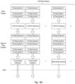
- Figure 8A shows the method according to the invention for improving the forward error correction and shows in particular the method steps which are carried out at the transmitter end.
- the arrows below in the present Figure 8A correspond to the arrow at the top of the following one Figure 8B . So the data will be according to Figure 8A is input and then the partial forward error correction is calculated. As can be seen above, all segments are of the same bit length. This means that the first column has 11 bits, the second column has 11 bits and the last column has 6 bits.
- a partial forward error correction is now generated for all segments with the same bit sequence, which has the same bit length as the corresponding segments. This results in the data with a parity symbol.
- the serial line coding takes place, which maps, for example, 11 bits to 12 bits or maps 11 bits to 13 bits or maps 6 bits to 8 bits. This data can now be transmitted over the potentially interference-prone channel. This leads to a transfer like that in the Figure 8A is shown below or in the present one Figure 8B is drawn above.
- Figure 8B shows the procedure on the receiver side and corresponds to the procedure from Figure 8A inverse.
- bit errors may be present, which, however, can be treated particularly advantageously at segment level. The bit errors therefore do not occur in the entire bit sequence, but only in individual segments and can therefore be treated advantageously. This leads to the corrected data as shown in the Figure 8B are plotted below and thus the 112 bits are recovered as shown in the Figure 8A served as an exit.
- figure 9 shows a flow chart of a method in an automobile for generating an efficiently transmittable bit sequence with a limited disparity, a limited run length and a line-coded forward error correction, having a provision 100 of any bit sequence; a segmentation 101 of the provided bit sequence into a previously defined sequence of segments according to a respectively previously defined bit length; calculating 101A a forward error correction for each of the segments or a plurality of segments of the same bit length; a coding 102 of each segment or a multiplicity of segments with the same bit position together with its/their Forward error correction in one or more sub-symbols, using the same coding unit for the segments with the same bit position and the associated forward error correction from a plurality of coding units, with a first subset of coding units determining a sign of the disparity of the sub-symbol by inverting the disparity of the sub-symbol generated to compensate for a Actively controls the disparity of a second subset of coding units, with a juxtaposition of
- all segment line codes and all partial forward error correction line codes are transmitted: In this last step, all generated segment line codes and partial forward error correction line codes are transmitted. These transmitted codes contain the error detection and correction information for the corresponding segments and partial forward error corrections.
- the method described enables improved forward error correction in serial coding and data transmission in the vehicle. By dividing the user data into segments and applying specific coding methods to these segments, effective error detection and correction is achieved at segment level.
- Targeted error correction for the transmitted data is made possible by the iterative creation of a partial forward error correction for all segments with the same bit position and the application of a segment coder to each segment.
- the partial forward error correction line codes contain the necessary information to detect and correct errors, while the segment line codes represent the structure and content of the segments and also contribute to error detection and correction.
- the receiver can appropriately analyze the received data and detect and correct errors to ensure reliable and accurate in-vehicle payload data transmission.
- the method described thus offers improved forward error correction, which is of great importance in particular in demanding environments such as vehicles, where interference and signal loss can occur. It helps to ensure reliable and high-quality data transmission, which is important for various Vehicle applications are of great importance, such as autonomous driving, vehicle safety systems and infotainment applications.
- the invention makes it possible to retain all desired properties and requirements for the serial coding at all times with efficient operation of an FEC.
- the serial encoder By deliberately positioning the serial encoder after the FEC units, the physical behavior on the link is always deterministically controllable (not the case with Scrambler as serial encoding).
- the choice of the FEC symbol size based on the data word size of the respective serial sub-encoder always ensures that bit errors always propagate minimally (a defective line code symbol then only produces a defective FEC symbol).
- interleaving is generated through the use of several FEC sub-coders. This is possible without time-consuming manual nesting of the symbols, which would always require data (more latency and buffers) to be stored. This also makes it possible to correct burst errors, e.g. 112/128 bit errors at once.
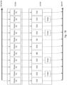
- figure 10 shows a data format which shows an arbitrary bit sequence on the left and partial symbols on the right.
- the data to be coded has 112 bits and the sub-symbols have 128 bits. In this way, any 112-bit bit sequence is encoded into a total symbol of 128 bits.
- the encoded 128 bits are optimized in terms of disparity.
- the center arrow indicates that the coding units translate the data segments on the left into sub-symbols on the right.
- the present figure also shows that the method can be used multiple times, so that any number of bit sequences can also be translated into any number of overall symbols.
- the data can be divided into different data cells or data frames.
- the data on the right side is coded in such a way that its disparity is optimized.
- the present method can be applied to any data, hence any bit sequence, and both user data and header data can be transferred.
- figure 11 shows the coding units together with the inputs and outputs in the middle.
- the output data are 112 bits, which in this case have the index 0-111. These are broken down into segments which have 11, 6, 7 or other assignments of bit lengths. In the present example, these segments are translated into sub-symbols of 12, 13, 8 or other data lengths.
- the proposed example is particularly advantageous because it encodes 112 bits into 128 bits, which achieves a particularly high level of efficiency.
- the 128 bits have the same content as the bit sequence to be encoded and are only 16 bits longer.
- the arbitrary bit sequence of 112 bits is segmented into, among other things, data segments of 11 bits and is then coded into 12 bits by means of the coding unit 11B12B.
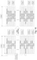
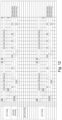
- figure 12 shows a data format such as that in figure 10 or 11 can find application. Again, the 128-bit total symbol is shown, as well as the arbitrary data sequence of 112 bits. Overall, the arbitrary bit sequence and the overall symbol can have different header data or frame data.
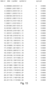
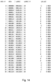
- a first table shows a conversion from 6 bits to 8 bits, a second table a conversion from 7 bits to 8 bits, a third table a conversion from 11 bits to 12 bits and a fourth table a conversion from 11 bits after 13 bits.
- segments of 6, 7 or 11 bits are converted into sub-symbols of 8, 12 or 13 bits.
- the codings shown are examples and illustrate the technical effect that is achieved here.
- the present invention was evaluated empirically and, using the proposed coding, achieves that 112 bits can be optimized with regard to their disparity in such a way that only 128 bits are required. This corresponds to a so-called overhead of only 14%.
- cells are used as a synonym for frames. These can also be packages.
- the cell consists of a header with a fixed bit length, a payload area with 4 selectable bit lengths and a footer again with a fixed bit length.
- the transmission frame consists of a sequence of M-bit wide words.
- the frame begins with an M-bit wide "point" word from a defined sequence of frame alignment point words. Then follows K cells.
- the cells consist of 2, 4, 6 or 8 N-bit wide words that carry a header, payload and footer. These N-bit wide words are coded into M-bit wide symbols (line coding).
- This format is chosen to allow cell data to be processed at reasonable time rates, provided that the serializer/deserializer is always processing a block of M bits.
- figure 13 shows a section of an exemplary coding of data segments to symbols, with 6 bits being coded to 8 bits in such a way that the disparity is optimized according to one aspect of the present invention.
- a segment becomes 000000 encoded to a sub-symbol 00101011, i.e. a 6B8B encoder.
- figure 14 a 7B8B encoder, figure 15 a 11B12B encoder and figure 16 a 11B13B encoder.
Landscapes
- Engineering & Computer Science (AREA)
- Computer Networks & Wireless Communication (AREA)
- Signal Processing (AREA)
- Physics & Mathematics (AREA)
- Theoretical Computer Science (AREA)
- Spectroscopy & Molecular Physics (AREA)
- Probability & Statistics with Applications (AREA)
- Dc Digital Transmission (AREA)
- Error Detection And Correction (AREA)
- Compression, Expansion, Code Conversion, And Decoders (AREA)
- Detection And Prevention Of Errors In Transmission (AREA)
Priority Applications (6)
| Application Number | Priority Date | Filing Date | Title |
|---|---|---|---|
| EP23180790.0A EP4236132A3 (fr) | 2023-06-21 | 2023-06-21 | Séquence binaire pouvant être transmise efficace avec disparité réduite et correction d'erreurs sans voie de retour codée par ligne |
| PCT/EP2024/055992 WO2024260592A1 (fr) | 2023-06-21 | 2024-03-07 | Séquence de bits pouvant être transmise efficacement avec disparité restreinte et correction d'erreur directe |
| CN202480041483.1A CN121359404A (zh) | 2023-06-21 | 2024-03-07 | 具有受限差异度和编码的前向错误纠正的可高效传输的位序列 |
| EP24709069.9A EP4732479A1 (fr) | 2023-06-21 | 2024-03-07 | Séquence de bits pouvant être transmise efficacement avec disparité restreinte et correction d'erreur directe |
| KR1020257040462A KR20260007248A (ko) | 2023-06-21 | 2024-03-07 | 제한된 불균형 및 코딩된 순방향 오류 정정을 갖는 효율적으로 전달 가능한 비트 시퀀스 |
| US19/425,573 US20260113145A1 (en) | 2023-06-21 | 2025-12-18 | Efficiently transmittable bit sequence with restricted disparity, and encoded forward error correction |
Applications Claiming Priority (1)
| Application Number | Priority Date | Filing Date | Title |
|---|---|---|---|
| EP23180790.0A EP4236132A3 (fr) | 2023-06-21 | 2023-06-21 | Séquence binaire pouvant être transmise efficace avec disparité réduite et correction d'erreurs sans voie de retour codée par ligne |
Publications (2)
| Publication Number | Publication Date |
|---|---|
| EP4236132A2 true EP4236132A2 (fr) | 2023-08-30 |
| EP4236132A3 EP4236132A3 (fr) | 2024-01-03 |
Family
ID=86942909
Family Applications (2)
| Application Number | Title | Priority Date | Filing Date |
|---|---|---|---|
| EP23180790.0A Pending EP4236132A3 (fr) | 2023-06-21 | 2023-06-21 | Séquence binaire pouvant être transmise efficace avec disparité réduite et correction d'erreurs sans voie de retour codée par ligne |
| EP24709069.9A Pending EP4732479A1 (fr) | 2023-06-21 | 2024-03-07 | Séquence de bits pouvant être transmise efficacement avec disparité restreinte et correction d'erreur directe |
Family Applications After (1)
| Application Number | Title | Priority Date | Filing Date |
|---|---|---|---|
| EP24709069.9A Pending EP4732479A1 (fr) | 2023-06-21 | 2024-03-07 | Séquence de bits pouvant être transmise efficacement avec disparité restreinte et correction d'erreur directe |
Country Status (5)
| Country | Link |
|---|---|
| US (1) | US20260113145A1 (fr) |
| EP (2) | EP4236132A3 (fr) |
| KR (1) | KR20260007248A (fr) |
| CN (1) | CN121359404A (fr) |
| WO (1) | WO2024260592A1 (fr) |
Citations (3)
| Publication number | Priority date | Publication date | Assignee | Title |
|---|---|---|---|---|
| US5398237A (en) * | 1993-05-26 | 1995-03-14 | Gi Corporation | Acquisition and tracking of independent quadrature modulated bitstreams |
| US5440347A (en) * | 1993-05-07 | 1995-08-08 | Philips Electronics North America Corporation | Method and apparatus for randomizing training sequences to minimize interference in digital transmissions |
| EP3323219A1 (fr) | 2015-07-15 | 2018-05-23 | INOVA Semiconductors GmbH | Procédé, dispositif et système pour la détermination côté récepteur d'un instant de balayage |
Family Cites Families (5)
| Publication number | Priority date | Publication date | Assignee | Title |
|---|---|---|---|---|
| US4486739A (en) * | 1982-06-30 | 1984-12-04 | International Business Machines Corporation | Byte oriented DC balanced (0,4) 8B/10B partitioned block transmission code |
| GB8912471D0 (en) * | 1989-05-31 | 1989-07-19 | Int Computers Ltd | Data transmission code |
| US7296211B2 (en) * | 2002-06-25 | 2007-11-13 | Lockheed Martin Corporation | System and method for transferring data on a data link |
| US7103830B1 (en) * | 2002-12-18 | 2006-09-05 | Applied Micro Circuits Corporation | DC balanced error correction coding |
| US9379846B1 (en) * | 2014-12-19 | 2016-06-28 | Cadence Design Systems, Inc. | System and method of encoding in a serializer/deserializer |
-
2023
- 2023-06-21 EP EP23180790.0A patent/EP4236132A3/fr active Pending
-
2024
- 2024-03-07 KR KR1020257040462A patent/KR20260007248A/ko active Pending
- 2024-03-07 CN CN202480041483.1A patent/CN121359404A/zh active Pending
- 2024-03-07 WO PCT/EP2024/055992 patent/WO2024260592A1/fr not_active Ceased
- 2024-03-07 EP EP24709069.9A patent/EP4732479A1/fr active Pending
-
2025
- 2025-12-18 US US19/425,573 patent/US20260113145A1/en active Pending
Patent Citations (3)
| Publication number | Priority date | Publication date | Assignee | Title |
|---|---|---|---|---|
| US5440347A (en) * | 1993-05-07 | 1995-08-08 | Philips Electronics North America Corporation | Method and apparatus for randomizing training sequences to minimize interference in digital transmissions |
| US5398237A (en) * | 1993-05-26 | 1995-03-14 | Gi Corporation | Acquisition and tracking of independent quadrature modulated bitstreams |
| EP3323219A1 (fr) | 2015-07-15 | 2018-05-23 | INOVA Semiconductors GmbH | Procédé, dispositif et système pour la détermination côté récepteur d'un instant de balayage |
Also Published As
| Publication number | Publication date |
|---|---|
| WO2024260592A1 (fr) | 2024-12-26 |
| EP4236132A3 (fr) | 2024-01-03 |
| US20260113145A1 (en) | 2026-04-23 |
| KR20260007248A (ko) | 2026-01-13 |
| CN121359404A (zh) | 2026-01-16 |
| EP4732479A1 (fr) | 2026-04-29 |
Similar Documents
| Publication | Publication Date | Title |
|---|---|---|
| DE102007016461B4 (de) | Verfahren zum Übertragen DC-balance-kodierter Daten, Verfahren zum Reduzieren von Simultaneous Switching Noise, Datensender, Datenempfänger und Daten-Sender/ Empfänger | |
| DE3689733T2 (de) | Gerät zur Übertragung von Datenbitgruppen und Verfahren zur Beurteilung der mit der grössten Wahrscheinlichkeit übertragenen Sequenz. | |
| DE19846721B4 (de) | Verfahren zur Kodierung und Dekodierung und Vorrichtung zum Kodieren oder Dekodieren | |
| DE102006023878A1 (de) | Codieren und Decodieren von paketierten Daten | |
| DE69032076T2 (de) | Einrichtung für Datenkodierung und Vorwärts-Fehlerkorrektur für eine niedrige Offset-Gleichspannung und eine kurze Lauflänge | |
| EP4236219B1 (fr) | Séquence binaire pouvant être transmise efficacement à disparité limitée | |
| EP4236132A2 (fr) | Séquence binaire pouvant être transmise efficace avec disparité réduite et correction d'erreurs sans voie de retour codée par ligne | |
| DE69901765T2 (de) | Turbo-Code Dekodierer | |
| DE112018008223T5 (de) | Vorrichtung und Verfahren zum Senden von Seitenkanalbits auf einem Ethernet-Kabel | |
| DE102008040797B4 (de) | Verfahren zum Empfangen eines Datenblocks | |
| EP4595418A1 (fr) | Fonctionnement d'un système universel de transport de données | |
| EP4236131A2 (fr) | Procédé et dispositif pour améliorer la correction d'erreurs sans voie de retour dans le codage en série dans une transmission de données | |
| EP4250572A2 (fr) | Procédé et système pour calculer une correction d'erreur sans voie de retour avec un nombre réduit de portes dans des codeurs fec | |
| EP4236265B1 (fr) | Transfert de données efficace et basé sur le matériel | |
| DE102008055139B4 (de) | Verfahren zum Empfangen eines Datenblocks | |
| DE102018213065A1 (de) | Fehlerkorrekturverfahren für unidirektionalen Datentransfer | |
| DE102016201408B4 (de) | Verfahren zum Übertragen von Daten | |
| DE102010032218A1 (de) | Verfahren zur paketvermittelten Datenübertragung, insbesondere zwischen einem Transportmittel und einer mit dem Transportmittel kommunizierenden Infrastruktur | |
| DE102011115100B3 (de) | Verfahren zum Wiederherstellen von verloren gegangenen und/oder beschädigten Daten | |
| DE102017223776A1 (de) | Teilnehmerstation für ein serielles Kommunikationsnetzwerk und Verfahren zur Korrektur von Einzelfehlern in einer Nachricht eines seriellen Kommunikationsnetzwerks | |
| DE102015205290A1 (de) | Verfahren zur Übertragung von binären Daten über einen Kanal, insbesondere über einen optischen Freiraum-Datenübertragungskanal | |
| DE2304344B2 (de) | Verfahren zur Kompression des Nachrichtenflusses bei digitaler Bildübertragung | |
| WO2002045324A1 (fr) | Procede pour restituer des donnees et dispositif associe |
Legal Events
| Date | Code | Title | Description |
|---|---|---|---|
| PUAI | Public reference made under article 153(3) epc to a published international application that has entered the european phase |
Free format text: ORIGINAL CODE: 0009012 |
|
| STAA | Information on the status of an ep patent application or granted ep patent |
Free format text: STATUS: REQUEST FOR EXAMINATION WAS MADE |
|
| 17P | Request for examination filed |
Effective date: 20230703 |
|
| AK | Designated contracting states |
Kind code of ref document: A2 Designated state(s): AL AT BE BG CH CY CZ DE DK EE ES FI FR GB GR HR HU IE IS IT LI LT LU LV MC ME MK MT NL NO PL PT RO RS SE SI SK SM TR |
|
| PUAL | Search report despatched |
Free format text: ORIGINAL CODE: 0009013 |
|
| STAA | Information on the status of an ep patent application or granted ep patent |
Free format text: STATUS: EXAMINATION IS IN PROGRESS |
|
| AK | Designated contracting states |
Kind code of ref document: A3 Designated state(s): AL AT BE BG CH CY CZ DE DK EE ES FI FR GB GR HR HU IE IS IT LI LT LU LV MC ME MK MT NL NO PL PT RO RS SE SI SK SM TR |
|
| RIC1 | Information provided on ipc code assigned before grant |
Ipc: H03M 13/31 20060101ALI20231130BHEP Ipc: H03M 13/05 20060101ALI20231130BHEP Ipc: H04L 25/49 20060101ALI20231130BHEP Ipc: H04L 1/00 20060101AFI20231130BHEP |
|
| 17Q | First examination report despatched |
Effective date: 20231218 |
|
| RAP3 | Party data changed (applicant data changed or rights of an application transferred) |
Owner name: INOVA SEMICONDUCTORS |