EP4236304A1 - Kameramodul, informationsverarbeitungssystem, informationsverarbeitungsverfahren und informationsverarbeitungsvorrichtung - Google Patents
Kameramodul, informationsverarbeitungssystem, informationsverarbeitungsverfahren und informationsverarbeitungsvorrichtung Download PDFInfo
- Publication number
- EP4236304A1 EP4236304A1 EP21882628.7A EP21882628A EP4236304A1 EP 4236304 A1 EP4236304 A1 EP 4236304A1 EP 21882628 A EP21882628 A EP 21882628A EP 4236304 A1 EP4236304 A1 EP 4236304A1
- Authority
- EP
- European Patent Office
- Prior art keywords
- camera
- vehicle
- display
- moving device
- optical axis
- Prior art date
- Legal status (The legal status is an assumption and is not a legal conclusion. Google has not performed a legal analysis and makes no representation as to the accuracy of the status listed.)
- Withdrawn
Links
Images


Classifications
-
- B—PERFORMING OPERATIONS; TRANSPORTING
- B60—VEHICLES IN GENERAL
- B60R—VEHICLES, VEHICLE FITTINGS, OR VEHICLE PARTS, NOT OTHERWISE PROVIDED FOR
- B60R1/00—Optical viewing arrangements; Real-time viewing arrangements for drivers or passengers using optical image capturing systems, e.g. cameras or video systems specially adapted for use in or on vehicles
- B60R1/20—Real-time viewing arrangements for drivers or passengers using optical image capturing systems, e.g. cameras or video systems specially adapted for use in or on vehicles
- B60R1/22—Real-time viewing arrangements for drivers or passengers using optical image capturing systems, e.g. cameras or video systems specially adapted for use in or on vehicles for viewing an area outside the vehicle, e.g. the exterior of the vehicle
- B60R1/23—Real-time viewing arrangements for drivers or passengers using optical image capturing systems, e.g. cameras or video systems specially adapted for use in or on vehicles for viewing an area outside the vehicle, e.g. the exterior of the vehicle with a predetermined field of view
- B60R1/27—Real-time viewing arrangements for drivers or passengers using optical image capturing systems, e.g. cameras or video systems specially adapted for use in or on vehicles for viewing an area outside the vehicle, e.g. the exterior of the vehicle with a predetermined field of view providing all-round vision, e.g. using omnidirectional cameras
-
- H—ELECTRICITY
- H04—ELECTRIC COMMUNICATION TECHNIQUE
- H04N—PICTORIAL COMMUNICATION, e.g. TELEVISION
- H04N7/00—Television systems
- H04N7/18—Closed-circuit television [CCTV] systems, i.e. systems in which the video signal is not broadcast
- H04N7/183—Closed-circuit television [CCTV] systems, i.e. systems in which the video signal is not broadcast for receiving images from a single remote source
-
- B—PERFORMING OPERATIONS; TRANSPORTING
- B60—VEHICLES IN GENERAL
- B60R—VEHICLES, VEHICLE FITTINGS, OR VEHICLE PARTS, NOT OTHERWISE PROVIDED FOR
- B60R1/00—Optical viewing arrangements; Real-time viewing arrangements for drivers or passengers using optical image capturing systems, e.g. cameras or video systems specially adapted for use in or on vehicles
- B60R1/20—Real-time viewing arrangements for drivers or passengers using optical image capturing systems, e.g. cameras or video systems specially adapted for use in or on vehicles
- B60R1/22—Real-time viewing arrangements for drivers or passengers using optical image capturing systems, e.g. cameras or video systems specially adapted for use in or on vehicles for viewing an area outside the vehicle, e.g. the exterior of the vehicle
- B60R1/23—Real-time viewing arrangements for drivers or passengers using optical image capturing systems, e.g. cameras or video systems specially adapted for use in or on vehicles for viewing an area outside the vehicle, e.g. the exterior of the vehicle with a predetermined field of view
- B60R1/24—Real-time viewing arrangements for drivers or passengers using optical image capturing systems, e.g. cameras or video systems specially adapted for use in or on vehicles for viewing an area outside the vehicle, e.g. the exterior of the vehicle with a predetermined field of view in front of the vehicle
-
- B—PERFORMING OPERATIONS; TRANSPORTING
- B60—VEHICLES IN GENERAL
- B60R—VEHICLES, VEHICLE FITTINGS, OR VEHICLE PARTS, NOT OTHERWISE PROVIDED FOR
- B60R1/00—Optical viewing arrangements; Real-time viewing arrangements for drivers or passengers using optical image capturing systems, e.g. cameras or video systems specially adapted for use in or on vehicles
- B60R1/20—Real-time viewing arrangements for drivers or passengers using optical image capturing systems, e.g. cameras or video systems specially adapted for use in or on vehicles
- B60R1/22—Real-time viewing arrangements for drivers or passengers using optical image capturing systems, e.g. cameras or video systems specially adapted for use in or on vehicles for viewing an area outside the vehicle, e.g. the exterior of the vehicle
- B60R1/23—Real-time viewing arrangements for drivers or passengers using optical image capturing systems, e.g. cameras or video systems specially adapted for use in or on vehicles for viewing an area outside the vehicle, e.g. the exterior of the vehicle with a predetermined field of view
- B60R1/25—Real-time viewing arrangements for drivers or passengers using optical image capturing systems, e.g. cameras or video systems specially adapted for use in or on vehicles for viewing an area outside the vehicle, e.g. the exterior of the vehicle with a predetermined field of view to the sides of the vehicle
-
- B—PERFORMING OPERATIONS; TRANSPORTING
- B60—VEHICLES IN GENERAL
- B60R—VEHICLES, VEHICLE FITTINGS, OR VEHICLE PARTS, NOT OTHERWISE PROVIDED FOR
- B60R1/00—Optical viewing arrangements; Real-time viewing arrangements for drivers or passengers using optical image capturing systems, e.g. cameras or video systems specially adapted for use in or on vehicles
- B60R1/20—Real-time viewing arrangements for drivers or passengers using optical image capturing systems, e.g. cameras or video systems specially adapted for use in or on vehicles
- B60R1/22—Real-time viewing arrangements for drivers or passengers using optical image capturing systems, e.g. cameras or video systems specially adapted for use in or on vehicles for viewing an area outside the vehicle, e.g. the exterior of the vehicle
- B60R1/23—Real-time viewing arrangements for drivers or passengers using optical image capturing systems, e.g. cameras or video systems specially adapted for use in or on vehicles for viewing an area outside the vehicle, e.g. the exterior of the vehicle with a predetermined field of view
- B60R1/26—Real-time viewing arrangements for drivers or passengers using optical image capturing systems, e.g. cameras or video systems specially adapted for use in or on vehicles for viewing an area outside the vehicle, e.g. the exterior of the vehicle with a predetermined field of view to the rear of the vehicle
-
- H—ELECTRICITY
- H04—ELECTRIC COMMUNICATION TECHNIQUE
- H04N—PICTORIAL COMMUNICATION, e.g. TELEVISION
- H04N23/00—Cameras or camera modules comprising electronic image sensors; Control thereof
- H04N23/50—Constructional details
- H04N23/51—Housings
-
- H—ELECTRICITY
- H04—ELECTRIC COMMUNICATION TECHNIQUE
- H04N—PICTORIAL COMMUNICATION, e.g. TELEVISION
- H04N23/00—Cameras or camera modules comprising electronic image sensors; Control thereof
- H04N23/57—Mechanical or electrical details of cameras or camera modules specially adapted for being embedded in other devices
-
- H—ELECTRICITY
- H04—ELECTRIC COMMUNICATION TECHNIQUE
- H04N—PICTORIAL COMMUNICATION, e.g. TELEVISION
- H04N23/00—Cameras or camera modules comprising electronic image sensors; Control thereof
- H04N23/90—Arrangement of cameras or camera modules, e.g. multiple cameras in TV studios or sports stadiums
-
- H—ELECTRICITY
- H04—ELECTRIC COMMUNICATION TECHNIQUE
- H04N—PICTORIAL COMMUNICATION, e.g. TELEVISION
- H04N7/00—Television systems
- H04N7/18—Closed-circuit television [CCTV] systems, i.e. systems in which the video signal is not broadcast
- H04N7/181—Closed-circuit television [CCTV] systems, i.e. systems in which the video signal is not broadcast for receiving images from a plurality of remote sources
-
- B—PERFORMING OPERATIONS; TRANSPORTING
- B60—VEHICLES IN GENERAL
- B60R—VEHICLES, VEHICLE FITTINGS, OR VEHICLE PARTS, NOT OTHERWISE PROVIDED FOR
- B60R2300/00—Details of viewing arrangements using cameras and displays, specially adapted for use in a vehicle
- B60R2300/10—Details of viewing arrangements using cameras and displays, specially adapted for use in a vehicle characterised by the type of camera system used
- B60R2300/105—Details of viewing arrangements using cameras and displays, specially adapted for use in a vehicle characterised by the type of camera system used using multiple cameras
-
- B—PERFORMING OPERATIONS; TRANSPORTING
- B60—VEHICLES IN GENERAL
- B60R—VEHICLES, VEHICLE FITTINGS, OR VEHICLE PARTS, NOT OTHERWISE PROVIDED FOR
- B60R2300/00—Details of viewing arrangements using cameras and displays, specially adapted for use in a vehicle
- B60R2300/10—Details of viewing arrangements using cameras and displays, specially adapted for use in a vehicle characterised by the type of camera system used
- B60R2300/108—Details of viewing arrangements using cameras and displays, specially adapted for use in a vehicle characterised by the type of camera system used using 'non-standard' camera systems, e.g. camera sensor used for additional purposes i.a. rain sensor, camera sensor split in multiple image areas
-
- B—PERFORMING OPERATIONS; TRANSPORTING
- B60—VEHICLES IN GENERAL
- B60R—VEHICLES, VEHICLE FITTINGS, OR VEHICLE PARTS, NOT OTHERWISE PROVIDED FOR
- B60R2300/00—Details of viewing arrangements using cameras and displays, specially adapted for use in a vehicle
- B60R2300/20—Details of viewing arrangements using cameras and displays, specially adapted for use in a vehicle characterised by the type of display used
- B60R2300/207—Details of viewing arrangements using cameras and displays, specially adapted for use in a vehicle characterised by the type of display used using multi-purpose displays, e.g. camera image and navigation or video on same display
-
- B—PERFORMING OPERATIONS; TRANSPORTING
- B60—VEHICLES IN GENERAL
- B60R—VEHICLES, VEHICLE FITTINGS, OR VEHICLE PARTS, NOT OTHERWISE PROVIDED FOR
- B60R2300/00—Details of viewing arrangements using cameras and displays, specially adapted for use in a vehicle
- B60R2300/30—Details of viewing arrangements using cameras and displays, specially adapted for use in a vehicle characterised by the type of image processing
- B60R2300/301—Details of viewing arrangements using cameras and displays, specially adapted for use in a vehicle characterised by the type of image processing combining image information with other obstacle sensor information, e.g. using RADAR/LIDAR/SONAR sensors for estimating risk of collision
-
- B—PERFORMING OPERATIONS; TRANSPORTING
- B60—VEHICLES IN GENERAL
- B60R—VEHICLES, VEHICLE FITTINGS, OR VEHICLE PARTS, NOT OTHERWISE PROVIDED FOR
- B60R2300/00—Details of viewing arrangements using cameras and displays, specially adapted for use in a vehicle
- B60R2300/30—Details of viewing arrangements using cameras and displays, specially adapted for use in a vehicle characterised by the type of image processing
- B60R2300/302—Details of viewing arrangements using cameras and displays, specially adapted for use in a vehicle characterised by the type of image processing combining image information with GPS information or vehicle data, e.g. vehicle speed, gyro, steering angle data
-
- B—PERFORMING OPERATIONS; TRANSPORTING
- B60—VEHICLES IN GENERAL
- B60R—VEHICLES, VEHICLE FITTINGS, OR VEHICLE PARTS, NOT OTHERWISE PROVIDED FOR
- B60R2300/00—Details of viewing arrangements using cameras and displays, specially adapted for use in a vehicle
- B60R2300/30—Details of viewing arrangements using cameras and displays, specially adapted for use in a vehicle characterised by the type of image processing
- B60R2300/307—Details of viewing arrangements using cameras and displays, specially adapted for use in a vehicle characterised by the type of image processing virtually distinguishing relevant parts of a scene from the background of the scene
-
- B—PERFORMING OPERATIONS; TRANSPORTING
- B60—VEHICLES IN GENERAL
- B60R—VEHICLES, VEHICLE FITTINGS, OR VEHICLE PARTS, NOT OTHERWISE PROVIDED FOR
- B60R2300/00—Details of viewing arrangements using cameras and displays, specially adapted for use in a vehicle
- B60R2300/60—Details of viewing arrangements using cameras and displays, specially adapted for use in a vehicle characterised by monitoring and displaying vehicle exterior scenes from a transformed perspective
- B60R2300/602—Details of viewing arrangements using cameras and displays, specially adapted for use in a vehicle characterised by monitoring and displaying vehicle exterior scenes from a transformed perspective with an adjustable viewpoint
-
- B—PERFORMING OPERATIONS; TRANSPORTING
- B60—VEHICLES IN GENERAL
- B60R—VEHICLES, VEHICLE FITTINGS, OR VEHICLE PARTS, NOT OTHERWISE PROVIDED FOR
- B60R2300/00—Details of viewing arrangements using cameras and displays, specially adapted for use in a vehicle
- B60R2300/70—Details of viewing arrangements using cameras and displays, specially adapted for use in a vehicle characterised by an event-triggered choice to display a specific image among a selection of captured images
-
- B—PERFORMING OPERATIONS; TRANSPORTING
- B60—VEHICLES IN GENERAL
- B60R—VEHICLES, VEHICLE FITTINGS, OR VEHICLE PARTS, NOT OTHERWISE PROVIDED FOR
- B60R2300/00—Details of viewing arrangements using cameras and displays, specially adapted for use in a vehicle
- B60R2300/80—Details of viewing arrangements using cameras and displays, specially adapted for use in a vehicle characterised by the intended use of the viewing arrangement
- B60R2300/804—Details of viewing arrangements using cameras and displays, specially adapted for use in a vehicle characterised by the intended use of the viewing arrangement for lane monitoring
-
- B—PERFORMING OPERATIONS; TRANSPORTING
- B60—VEHICLES IN GENERAL
- B60R—VEHICLES, VEHICLE FITTINGS, OR VEHICLE PARTS, NOT OTHERWISE PROVIDED FOR
- B60R2300/00—Details of viewing arrangements using cameras and displays, specially adapted for use in a vehicle
- B60R2300/80—Details of viewing arrangements using cameras and displays, specially adapted for use in a vehicle characterised by the intended use of the viewing arrangement
- B60R2300/8046—Details of viewing arrangements using cameras and displays, specially adapted for use in a vehicle characterised by the intended use of the viewing arrangement for replacing a rear-view mirror system
-
- B—PERFORMING OPERATIONS; TRANSPORTING
- B60—VEHICLES IN GENERAL
- B60R—VEHICLES, VEHICLE FITTINGS, OR VEHICLE PARTS, NOT OTHERWISE PROVIDED FOR
- B60R2300/00—Details of viewing arrangements using cameras and displays, specially adapted for use in a vehicle
- B60R2300/80—Details of viewing arrangements using cameras and displays, specially adapted for use in a vehicle characterised by the intended use of the viewing arrangement
- B60R2300/8066—Details of viewing arrangements using cameras and displays, specially adapted for use in a vehicle characterised by the intended use of the viewing arrangement for monitoring rearward traffic
Definitions
- the present technology relates to a camera module, an information processing system, an information processing method, and an information processing apparatus, and more particularly, to a camera module, an information processing system, an information processing method, and an information processing apparatus that enable effective use of a camera in a moving device.
- CMS camera monitoring system
- a door mirror used for the CMS there has been proposed a door mirror including a main camera that is both directed to the rear of the vehicle and captures an image to be displayed on a display in the vehicle, and a sub camera that detects fogging of a lens or the like (See, for example, Patent Documents 1 and 2.).
- the present technology has been made in view of such a situation, and is to suppress complication of a system including a camera in a moving device such as a vehicle.
- a camera module includes a first camera, a second camera, and a housing that stores the first camera and the second camera, in which in a state of being installed in a moving device, an optical axis of the first camera faces obliquely rearward of the moving device, and an optical axis of the second camera faces in a lateral direction or obliquely forward of the moving device.
- an optical axis of the first camera faces obliquely rearward of the moving device
- an optical axis of the second camera faces in a lateral direction or obliquely forward of the moving device.
- display of an image based on the first image captured by the first camera whose optical axis faces obliquely rearward of the moving device is controlled, external object recognition of the moving device is performed on the basis of the second image captured by the second camera that is stored in the housing same as the first camera and includes an optical axis facing a direction closer to a front direction of the moving device than the optical axis of the first camera, and display of a visual effect based on a result of the object recognition is controlled.
- display of an image based on a first image captured by a first camera whose optical axis faces obliquely rearward of the moving device, and a visual effect based on a result of external object recognition of the moving device based on a second image captured by a second camera that is stored in the housing same as the first camera and that includes an optical axis facing a direction closer to the front direction of the moving device than the optical axis of the first camera is controlled.
- Fig. 1 is a block diagram illustrating a configuration example of a vehicle control system 11 that is an example of a moving device control system to which the present technology is applied.
- the vehicle control system 11 is provided in the vehicle 1 and performs processing related to travel assistance and automated driving of the vehicle 1.
- the vehicle control system 11 includes a processor 21, a communication unit 22, a map information accumulation unit 23, a global navigation satellite system (GNSS) reception unit 24, an external recognition sensor 25, an in-vehicle sensor 26, a vehicle sensor 27, a recording unit 28, a travel support/automated driving control unit 29, a driver monitoring system (DMS) 30, a human machine interface (HMI) 31, and a vehicle control unit 32.
- GNSS global navigation satellite system
- DMS driver monitoring system
- HMI human machine interface
- the processor 21, the communication unit 22, the map information accumulation unit 23, the GNSS reception unit 24, the external recognition sensor 25, the in-vehicle sensor 26, the vehicle sensor 27, the recording unit 28, the travel support/automated driving control unit 29, the driver monitoring system (DMS) 30, the human machine interface (HMI) 31, and the vehicle control unit 32 are connected to one another via a communication network 41.
- the communication network 41 includes, for example, an in-vehicle communication network, a bus, or the like conforming to an arbitrary standard such as a controller area network (CAN), a local interconnect network (LIN), a local area network (LAN), FlexRay (registered trademark), or Ethernet (registered trademark).
- CAN controller area network
- LIN local interconnect network
- LAN local area network
- FlexRay registered trademark
- Ethernet registered trademark
- each unit of the vehicle control system 11 performs communication via the communication network 41
- description of the communication network 41 will be omitted.
- the processor 21 and the communication unit 22 perform communication via the communication network 41, it is simply described that the processor 21 and the communication unit 22 perform communication.
- the processor 21 includes, for example, various processors such as a central processing unit (CPU), a micro processing unit (MPU), and an electronic control unit (ECU).
- CPU central processing unit
- MPU micro processing unit
- ECU electronice control unit
- the communication unit 22 communicates with various devices inside and outside the vehicle, other vehicles, servers, base stations, and the like, and transmits and receives various data.
- the communication unit 22 receives a program for updating software for controlling an operation of the vehicle control system 11, map information, traffic information, information around the vehicle 1, and the like from the outside.
- the communication unit 22 transmits information regarding the vehicle 1 (for example, data indicating the state of the vehicle 1, a recognition result by a recognition unit 73, and the like), information around the vehicle 1, and the like to the outside.
- the communication unit 22 performs communication corresponding to a vehicle emergency call system such as an eCall.
- a communication method of the communication unit 22 is not particularly limited. Furthermore, a plurality of communication methods may be used.
- the communication unit 22 performs wireless communication with an in-vehicle device by a communication method such as wireless LAN, Bluetooth, NFC, or wireless USB (WUSB).
- a communication method such as wireless LAN, Bluetooth, NFC, or wireless USB (WUSB).
- the communication unit 22 performs wired communication with an in-vehicle device by a communication method such as a universal serial bus (USB), a high-definition multimedia interface (registered trademark, HDMI), or a mobile high-definition link (MHL) via a connection terminal (and, if necessary, a cable) not illustrated.
- USB universal serial bus
- HDMI high-definition multimedia interface
- MHL mobile high-definition link
- the in-vehicle device is, for example, a device that is not connected to the communication network 41 in the vehicle.
- a mobile device or a wearable device carried by a passenger such as a driver, an information device brought into the vehicle and temporarily installed, or the like is assumed.
- the communication unit 22 communicates with a server or the like existing on an external network (for example, the Internet, a cloud network, or a company-specific network) via a base station or an access point by a wireless communication scheme such as fourth generation mobile communication system (4G), fifth generation mobile communication system (5G), long term evolution (LTE), or dedicated short range communications DSRC).
- 4G fourth generation mobile communication system
- 5G fifth generation mobile communication system
- LTE long term evolution
- DSRC dedicated short range communications
- the communication unit 22 communicates with a terminal (for example, a terminal of a pedestrian or a store, or a machine type communication (MTC) terminal) existing in the vicinity of the host vehicle using a peer to peer (P2P) technology.
- a terminal for example, a terminal of a pedestrian or a store, or a machine type communication (MTC) terminal
- MTC machine type communication
- P2P peer to peer
- the communication unit 22 performs V2X communication.
- the V2X communication is, for example, vehicle to vehicle communication with another vehicle, vehicle to infrastructure communication with a roadside device or the like, vehicle to home communication, vehicle to pedestrian communication with a terminal or the like possessed by a pedestrian, or the like.
- the communication unit 22 receives an electromagnetic wave transmitted by a vehicle information and communication system (VICS, registered trademark) such as a radio wave beacon, an optical beacon, or FM multiplex broadcasting.
- VICS vehicle information and communication system
- the map information accumulation unit 23 accumulates a map acquired from the outside and a map created by the vehicle 1. For example, the map information accumulation unit 23 accumulates a three-dimensional highly accurate map, a global map having lower accuracy than the highly accurate map and covering a wide area, and the like.
- the high-precision map is, for example, a dynamic map, a point cloud map, a vector map (is also referred to as an advanced driver assistance system (ADAS) map.), or the like.
- the dynamic map is, for example, a map including four layers of dynamic information, semidynamic information, semi-static information, and static information, and is provided from an external server or the like.
- the point cloud map is a map including point clouds (point cloud data).
- the vector map is a map in which information such as a lane and a position of a signal is associated with the point cloud map.
- the GNSS reception unit 24 receives a GNSS signal from a GNSS satellite, and supplies the GNSS signal to the travel support/automated driving control unit 29.
- the camera 51 for example, a camera of an arbitrary imaging system such as a time of flight (ToF) camera, a stereo camera, a monocular camera, or an infrared camera is used as necessary.
- a camera of an arbitrary imaging system such as a time of flight (ToF) camera, a stereo camera, a monocular camera, or an infrared camera is used as necessary.
- ToF time of flight
- stereo camera stereo camera
- monocular camera a monocular camera
- infrared camera infrared camera
- the in-vehicle sensor 26 includes a camera, a radar, a seating sensor, a steering wheel sensor, a microphone, a biological sensor, and the like.
- a camera for example, a camera of any imaging system such as a ToF camera, a stereo camera, a monocular camera, or an infrared camera can be used.
- the biological sensor is provided, for example, in a seat, a steering wheel, or the like, and detects various kinds of biological information of a passenger such as a driver.
- the vehicle sensor 27 includes various sensors for detecting the state of the vehicle 1, and supplies sensor data from each sensor to each unit of the vehicle control system 11.
- the type and number of sensors included in the vehicle sensor 27 are arbitrary.
- the vehicle sensor 27 includes a speed sensor, an acceleration sensor, an angular velocity sensor (gyro sensor), and an inertial measurement unit (IMU).
- the vehicle sensor 27 includes a steering angle sensor that detects a steering angle of a steering wheel, a yaw rate sensor, an accelerator sensor that detects an operation amount of an accelerator pedal, and a brake sensor that detects an operation amount of a brake pedal.
- the vehicle sensor 27 includes a rotation sensor that detects revolutions of an engine or a motor, an air pressure sensor that detects an air pressure of a tire, a slip rate sensor that detects a slip rate of a tire, and a wheel speed sensor that detects a rotation speed of a wheel.
- the vehicle sensor 27 includes a battery sensor that detects a remaining amount and a temperature of a battery, and an impact sensor that detects an external impact.
- the travel support/automated driving control unit 29 controls travel support and automated driving of the vehicle 1.
- the travel support/automated driving control unit 29 includes an analysis unit 61, an action planning unit 62, and an operation control unit 63.
- the analysis unit 61 performs analysis processing of the situation of the vehicle 1 and the surroundings.
- the analysis unit 61 includes a self-position estimation unit 71, a sensor fusion unit 72, and the recognition unit 73.
- the self-position estimation unit 71 estimates a self-position of the vehicle 1 on the basis of the sensor data from the external recognition sensor 25 and the high-precision map accumulated in the map information accumulation unit 23. For example, the self-position estimation unit 71 generates a local map on the basis of the sensor data from the external recognition sensor 25, and estimates the self-position of the vehicle 1 by matching the local map with the high-precision map.
- the position of the vehicle 1 is based on, for example, a center of a rear wheel pair axle.
- the local map is, for example, a three-dimensional high-precision map created using a technique such as simultaneous localization and mapping (SLAM), an occupancy grid map, or the like.
- the three-dimensional high-precision map is, for example, the above-described point cloud map or the like.
- the occupancy grid map is a map in which a three-dimensional or two-dimensional space around the vehicle 1 is divided into grids (lattices) of a predetermined size, and an occupancy state of an object is indicated in units of grids.
- the occupancy state of the object is indicated by, for example, the presence or absence or existence probability of the object.
- the local map is also used for detection processing and recognition processing of a situation outside the vehicle 1 by the recognition unit 73, for example.
- the self-position estimation unit 71 may estimate the self-position of the vehicle 1 on the basis of the GNSS signal and the sensor data from the vehicle sensor 27.
- the sensor fusion unit 72 performs sensor fusion processing of combining a plurality of different types of sensor data (for example, image data supplied from the camera 51 and sensor data supplied from the radar 52) to obtain new information.
- Methods of combining different types of sensor data include integration, fusion, association, and the like.
- the recognition unit 73 performs detection processing and recognition processing of a situation outside the vehicle 1.
- the recognition unit 73 performs detection processing and recognition processing of a situation outside the vehicle 1 on the basis of information from the external recognition sensor 25, information from the self-position estimation unit 71, information from the sensor fusion unit 72, and the like.
- the recognition unit 73 performs detection processing, recognition processing, and the like of an object around the vehicle 1.
- the detection processing of an object is, for example, processing of detecting the presence or absence, size, shape, position, movement, and the like of the object.
- the recognition processing of an object is, for example, processing of recognizing an attribute such as a type of an object or identifying a specific object.
- the detection processing and the recognition processing are not necessarily clearly divided, and may overlap.
- the recognition unit 73 detects the motion of an object around the vehicle 1 by performing tracking that follows the motion of the mass of the point cloud classified by clustering. As a result, speed and a traveling direction (movement vector) of the object around the vehicle 1 are detected.
- the recognition unit 73 recognizes the type of the object around the vehicle 1 by performing object recognition processing such as semantic segmentation on image data supplied from the camera 51.
- an object to be detected or recognized for example, a vehicle, a person, a bicycle, an obstacle, a structure, a road, a traffic light, a traffic sign, a road sign, and the like are assumed.
- the recognition unit 73 performs recognition processing of traffic rules around the vehicle 1 on the basis of the map accumulated in the map information accumulation unit 23, an estimation result of the self-position, and a recognition result of the object around the vehicle 1.
- this processing for example, the position and the state of the signal, the contents of the traffic sign and the road sign, the contents of the traffic regulation, the travelable lane, and the like are recognized.
- the recognition unit 73 performs recognition processing of the environment around the vehicle 1.
- the surrounding environment to be recognized for example, weather, temperature, humidity, brightness, a state of a road surface, and the like are assumed.
- the action planning unit 62 creates an action plan of the vehicle 1. For example, the action planning unit 62 creates an action plan by performing processing of global path planning and path following.
- the global path planning is processing of planning a rough path from a start to a goal.
- This global path planning is called trajectory planning, and includes processing of local path planning that enables safe and smooth traveling in the vicinity of the vehicle 1 in consideration of motion characteristics of the vehicle 1 in a path planned by the global path planning.
- the operation control unit 63 controls an operation of the vehicle 1 in order to realize the action plan created by the action planning unit 62.
- the operation control unit 63 controls a steering control unit 81, a brake control unit 82, and a drive control unit 83 to perform acceleration/deceleration control and direction control such that the vehicle 1 travels on a trajectory calculated by the trajectory planning.
- the operation control unit 63 performs cooperative control for the purpose of implementing the functions of the ADAS such as collision avoidance or impact mitigation, follow-up traveling, vehicle speed maintaining traveling, collision warning of the host vehicle, lane deviation warning of the host vehicle, and the like.
- the motion control unit 63 performs cooperative control for the purpose of automated driving or the like in which the vehicle autonomously travels without depending on the operation of the driver.
- the DMS 30 performs driver authentication processing, driver state recognition processing, and the like on the basis of sensor data from the in-vehicle sensor 26, input data input to the HMI 31, and the like.
- As the state of the driver to be recognized for example, a physical condition, a wakefulness level, a concentration level, a fatigue level, a line-of-sight direction, a drunkenness level, a driving operation, a posture, and the like are assumed.
- the DMS 30 may perform authentication processing of a passenger other than the driver and recognition processing of the state of the passenger. Furthermore, for example, the DMS 30 may perform recognition processing of the situation inside the vehicle on the basis of sensor data from the in-vehicle sensor 26. As the situation inside the vehicle to be recognized, for example, temperature, humidity, brightness, odor, and the like are assumed.
- the HMI 31 is used for inputting various data, instructions, and the like, generates an input signal on the basis of the input data, instructions, and the like, and supplies the input signal to each unit of the vehicle control system 11.
- the HMI 31 includes an operation device such as a touch panel, a button, a microphone, a switch, and a lever, an operation device that can be input by a method other than manual operation by voice, gesture, or the like, and the like.
- the HMI 31 may be, for example, a remote control device using infrared rays or other radio waves, or an external connection device such as a mobile device or a wearable device compatible with the operation of the vehicle control system 11.
- a display device As a device that outputs visual information, for example, a display device, a projector, a navigation device, an instrument panel, a camera monitoring system (CMS), an electronic mirror, a lamp, and the like are assumed.
- the display device may be a device that displays visual information in the field of view of the passenger, such as a head-up display, a transmissive display, or a wearable device having an augmented reality (AR) function, in addition to a device having a normal display.
- AR augmented reality
- an audio speaker for example, an audio speaker, a headphone, an earphone, or the like is assumed.
- a haptic element using haptics technology or the like As a device that outputs tactile information, for example, a haptic element using haptics technology or the like is assumed.
- the haptics element is provided, for example, on a steering wheel, a seat, or the like.
- the brake control unit 82 detects and controls the state of the brake system of the vehicle 1.
- the brake system includes, for example, a brake mechanism including a brake pedal, an antilock brake system (ABS), and the like.
- the brake control unit 82 includes, for example, a control unit such as an ECU that controls a brake system, an actuator that drives the brake system, and the like.
- the body system control unit 84 detects and controls the state of the body system of the vehicle 1.
- the body system includes, for example, a keyless entry system, a smart key system, a power window device, a power seat, an air conditioner, an airbag, a seat belt, a shift lever, and the like.
- the body system control unit 84 includes, for example, a control unit such as an ECU that controls the body system, an actuator that drives the body system, and the like.
- the light control unit 85 detects and controls states of various lights of the vehicle 1. As the light to be controlled, for example, a headlight, a backlight, a fog light, a turn signal, a brake light, a projection, a display of a bumper, and the like are assumed.
- the light control unit 85 includes a control unit such as an ECU that controls light, an actuator that drives light, and the like.
- the horn control unit 86 detects and controls the state of the car horn of the vehicle 1.
- the horn control unit 86 includes, for example, a control unit such as an ECU that controls the car horn, an actuator that drives the car horn, and the like.
- the camera 51FC1 is provided near the center of the front end of the vehicle 1.
- the camera 51FC1 images the front of the vehicle 1.
- a fisheye camera is used as the camera 51FC1.
- the camera 51FC1 is used for ADAS and surround view, for example.
- the surround view is, for example, a function of displaying an image of the periphery of the vehicle 1 or a bird's-eye view image of the periphery of the vehicle 1 as viewed from above.
- the camera 51FC2 is provided near the front center in the interior of the vehicle 1.
- the camera 51FC2 images the front of the vehicle 1 via the windshield.
- the camera 51FC2 is used for ADAS, for example.
- the image of the camera 51FC2 is recorded in, for example, a drive recorder.
- the camera 51FL and the camera 51FR are arranged on the left and right at a predetermined distance in front of the interior of the vehicle 1, and constitute a stereo camera.
- the camera 51FL and the camera 51FR image the front of the vehicle 1 via the windshield.
- the camera 51FL and the camera 51FR are used for ADAS, for example.
- As the camera 51FL and the camera 51FR for example, a camera having a higher resolution than the camera 51FC2 is used.
- the cameras 51SL1 to 51SL4 constitute one camera module 122L ( Fig. 9 and the like) as described later, and are provided near the front end of the door of the driver's seat on the left side surface of the vehicle 1.
- the camera 51SL2 images the left direction of the vehicle 1.
- the camera 51SL2 for example, a fisheye camera having a wider angle than the camera 51SL1, the camera 51SL3, and the camera 51SL4 is used.
- the camera 51SL2 is used for ADAS and surround view, for example.
- the camera 51SL3 images the left diagonal rear of the vehicle 1.
- a camera having a higher resolution than the camera 51SL1 is used.
- the camera 51SL3 is used for ADAS, for example.
- the camera 51SL4 images the left diagonal rear of the vehicle 1.
- the optical axis of the camera 51SL4 faces a direction closer to the rear side of the vehicle 1 than the optical axis of the camera 51SL3.
- the optical axis of the camera 51SL3 faces a direction closer to the left direction (lateral direction) of the vehicle 1 than the optical axis of the camera 51SL4.
- the camera 51SL4 is used, for example, for the CMS.
- the cameras 51SR1 to 51SR4 constitute one camera module 122R ( Fig. 4 and the like) as described later, and are provided near the front end of the door of the passenger seat on the right side surface of the vehicle 1.
- the camera 51SR1 images an oblique front right of the vehicle 1.
- the camera 51SR1 is used for, for example, an ADAS.
- the camera 51SR2 images the right direction of the vehicle 1.
- the camera 51SR2 for example, a fisheye camera having a wider angle than the camera 51SR1, the camera 51SR3, and the camera 51SR4 is used.
- the camera 51SR2 is used for ADAS and surround view, for example.
- the camera 51SR4 images the right diagonal rear of the vehicle 1.
- the optical axis of the camera 51SR4 faces a direction closer to the rear side of the vehicle 1 than the optical axis of the camera 51SR3.
- the optical axis of the camera 51SR3 faces a direction closer to the right direction (lateral direction) of the vehicle 1 than the optical axis of the camera 51SR4.
- the camera 51SR4 is used for the CMS, for example.
- the camera 51BC1 is provided near the center of the rear end of the vehicle 1.
- the camera 51BC1 images the rear of the vehicle 1.
- a fisheye camera is used as the camera 51BC1 .
- the camera 51BC1 is used for ADAS and surround view, for example.
- the camera 51BC2 and the camera 51BC3 are provided near the rear center in the interior of the vehicle 1.
- the camera 51BC2 and the camera 51BC3 image the rear of the vehicle 1 via the rear window.
- the camera 51BC2 is used for the CMS, for example.
- the camera 51BC3 is used for ADAS, for example.
- the image of the camera 51BC3 is recorded in, for example, a drive recorder.
- the radar 52FC is provided near the center of the tip of the vehicle 1.
- the radar 52FC performs sensing in front of the vehicle 1.
- the radar 52FL is provided near the left end of the front end of the vehicle 1.
- the radar 52FL performs sensing of the left diagonal front of the vehicle 1.
- the radar 52FR is provided near the right end of the front end of the vehicle 1.
- the radar 52FR performs sensing of diagonally forward right of the vehicle 1.
- the radar 52BC is provided near the center of the rear end of the vehicle 1.
- the radar 52BC performs sensing of the rear of the vehicle 1.
- the radar 52BL is provided near the left end of the rear end of the vehicle 1.
- the radar 52BL performs sensing of the left diagonal rear of the vehicle 1.
- the radar 52BR is provided near the right end of the rear end of the vehicle 1.
- the radar 52BR performs sensing of the right diagonal rear of the vehicle 1.
- the LiDAR 53L is provided in front of the left side surface of the vehicle 1.
- the LiDAR 53L performs sensing in the left direction of the vehicle 1.
- the LiDAR 53B is provided near the center of the rear end of the vehicle 1.
- the LiDAR 53B performs sensing of the rear of the vehicle 1.
- the ultrasonic sensor 54FL2 is provided near the left end of the front end of the vehicle 1.
- the ultrasonic sensor 54FL1 performs sensing in the forward diagonal left direction of the vehicle 1.
- the ultrasonic sensor 54FR1 is provided slightly to the right at the center of the front end of the vehicle 1.
- the ultrasonic sensor 54FR1 performs sensing toward the front right of the vehicle 1.
- the ultrasonic sensor 54SL1 is provided in front of the left side surface of the body of the vehicle 1.
- the ultrasonic sensor 54SL1 performs sensing in the left direction in front of the vehicle 1.
- the ultrasonic sensor 54SL2 is provided behind the left side surface of the body of the vehicle 1.
- the ultrasonic sensor 54SL2 performs sensing in the left direction behind the vehicle 1.
- the ultrasonic sensor 54SR1 is provided in front of the right side surface of the body of the vehicle 1.
- the ultrasonic sensor 54SR1 performs sensing in the right direction in front of the vehicle 1.
- the ultrasonic sensor 54SR2 is provided behind the right side surface of the body of the vehicle 1.
- the ultrasonic sensor 54SR2 performs sensing in the right direction behind the vehicle 1.
- the ultrasonic sensor 54BL is provided near the left end of the rear end of the vehicle 1.
- the ultrasonic sensor 54BL performs sensing in the rearward oblique left direction of the vehicle 1.
- the camera 102 is provided slightly to the left at the center on the dashboard in the vehicle.
- the camera 102 images around the driver's seat.
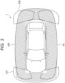
- Fig. 3 illustrates an example of imaging ranges of the camera 51FC1, the camera 51SL2, the camera 51SR2, and the camera 51BC1 using the fisheye camera.
- the camera 51FC1 can image the imaging range A1F exceeding 180 degrees in front of the vehicle 1.
- the camera 51SL2 can image an imaging range A1L exceeding 180 degrees in the left direction of the vehicle 1.
- the camera 51SR2 can image the imaging range A1R exceeding 180 degrees in the right direction of the vehicle 1.
- the camera 51BC1 can image an imaging range A1B exceeding 180 degrees behind the vehicle 1. Therefore, as indicated by hatching in the drawing, four fisheye cameras including the camera 51FC1 to the camera 51BC1 can image the periphery of the vehicle 1 at 360 degrees.
- the cameras 51FC1 to 51BC1 are used for the ADAS and the surround view. For example, by combining the images of the cameras 51FC1 to 51BC1, an overhead image of 360 degrees around the vehicle 1 viewed from above is generated and displayed.
- Fig. 4 is a front view of the vehicle 1.
- Fig. 5 is a left side view of the vehicle 1.
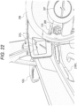
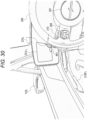
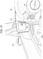
- the camera module 122L is provided at the similar position as a conventional door mirror on a door 121FL of the driver's seat. Specifically, the camera module 122L is provided near the front end of the body of the door 121FL of the driver's seat and near the boundary between the body and the window.
- the camera module 122R is provided at the similar position as the camera module 122L on a door 121FR (not illustrated) of the passenger seat.
- a of Fig. 6 is a schematic diagram of the periphery of the camera module 122L of the vehicle 1 as viewed from the front slightly oblique left direction.
- B of Fig. 6 is an exploded schematic view of a part of the camera module 122L viewed from substantially the same direction as A of Fig. 6 .
- a of Fig. 7 is a schematic diagram of the periphery of the camera module 122L of the vehicle 1 as viewed from the front diagonal left direction.
- B of Fig. 7 is an exploded schematic view of a part of the camera module 122L viewed from substantially the same direction as A of Fig. 7 .
- a of Fig. 6 is a schematic diagram of the periphery of the camera module 122L of the vehicle 1 as viewed from the front slightly oblique left direction.
- B of Fig. 6 is an exploded schematic view of a part of the camera module 122L viewed from substantially the same direction as A of Fig. 7 .
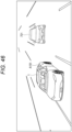
- FIG. 8 is a schematic view of the periphery of the camera module 122L of the vehicle 1 as viewed from the rear.
- B of Fig. 8 is a schematic diagram of the camera module 122L viewed from substantially the same direction as A of Fig. 8 .
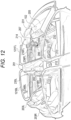
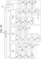
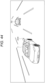
- Fig. 9 is an exploded view of the camera module 122L.
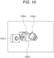
- Fig. 10 is a view of installation positions of the cameras 51SL1 to 51SL4 in the camera module 122L as viewed from the front.
- Fig. 11 is a view of installation positions of the cameras 51SL1 to 51SL4 in the camera module 122L as viewed from above.
- the cameras 51SL1 to 51SL4 are built in the housing 131L and fixed to the bottom plate of the housing 131L. Furthermore, the cameras 51SL1 to 51SL4 are directed in different directions outside the housing 131L so as not to be within the angle of view. Furthermore, a space is provided behind the cameras 51SL1 to 51SL4 so that cables can be wired.
- the camera 51SL1 is disposed such that the optical axis is horizontal and slightly obliquely leftward from the front of the vehicle 1, and the lens is seen from the front of the housing 131L. That is, the optical axis of the camera 51SL1 faces the horizontal direction of the vehicle 1 and faces a direction slightly rotated to the left from the front direction in the yaw direction of the vehicle 1.
- the angle of view of the camera 51SL1 is, for example, 120 degrees. Therefore, the camera 51SL1 can capture an image of a wide range from the front direction to the diagonally front left of the vehicle 1.
- the camera 51SL2 is disposed such that the optical axis is directed obliquely downward (for example, downward by 32 degrees from the horizontal direction) and leftward (laterally) of the vehicle 1, and the lens is seen from the left side surface of the housing 131L.
- the optical axis of the camera usually used for the surround view is oriented vertically downward.
- the optical axis of the camera 51SL2 is directed obliquely downward.
- the camera 51SL2 includes a fisheye camera. Therefore, the camera 51SL2 can capture an image of a wide range including from the ground around the left side of the vehicle 1 to the upper end of a vehicle, a motorbike, or the like in the left adjacent lane.
- the camera 51SL3 is disposed such that the optical axis is horizontal, faces the left diagonal rear direction of the vehicle 1, and the lens is seen from the left side surface of the housing 131L. That is, the optical axis of the camera 51SL3 faces the horizontal direction of the vehicle 1, and faces a direction rotated from the left direction to the left direction by a predetermined angle in the yaw direction of the vehicle 1.
- the angle of view of the camera 51SL3 is, for example, 120 degrees. Therefore, the camera 51SL3 can capture an image of a wide range including from the left direction to the left diagonal rear of the vehicle 1.
- the camera 51SL4 is disposed such that the optical axis is directed slightly obliquely downward and obliquely backward to the left of the vehicle 1, and the lens is seen from the vicinity of the boundary between the left side surface and the back surface of the housing 131L. That is, the optical axis of the camera 51SL4 is directed slightly downward from the horizontal direction of the vehicle 1, and is directed in a direction rotated from the left direction to the left direction by a predetermined angle in the yaw direction of the vehicle 1. Furthermore, the optical axis of the camera 51SL4 is directed in a direction closer to the rear side of the vehicle 1 than the optical axis of the camera 51SL3.
- the camera 51SL4 can image the left diagonal rear direction closer to the rear of the vehicle 1 than the camera 51SL3. Furthermore, by inclining the optical axis of the camera 51SL4 slightly downward from the horizontal direction, it is possible to widely image the road surface on the left diagonal rear side of the vehicle 1.
- the housing 131L has a width of 160 mm, a depth of 202 mm, and a height of 69 mm. Furthermore, the housing 131L includes metal, and can release the heat of the cameras 51SL1 to 51SL4 to the outside.
- the four cameras 51SL1 to 51SL4 having different imaging directions and applications are compactly arranged. Therefore, as compared with a case where the cameras 51SL1 to 51SL4 are individually arranged, the space of the vehicle 1 can be effectively used, and the designability is improved. Furthermore, the degree of freedom of arrangement of the cameras 51SL1 to 51SL4 (camera module 122L) is improved, and arrangement and wiring of sensors including other cameras are easily designed. As a result, it is possible to suppress complication of the system of the vehicle 1 including each camera and to make the system simpler.
- the cameras 51SR1 to 51SR4 are arranged so as to be bilaterally symmetrical with the cameras 51SL1 to 51SL4 in the camera module 122L.
- FIG. 16 A right diagram in Fig. 16 is a schematic diagram of the camera module 214 as viewed from the front obliquely downward direction.
- Fig. 17 illustrates an example of the imaging range of the camera 101L.
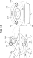
- Fig. 18 is a schematic diagram of the interior of the vehicle 1 as viewed from the front.
- Fig. 19 is a schematic diagram of the driver's seat 201 as viewed from diagonally behind on the left.
- the camera 102 is provided on a dashboard 205 slightly closer to the driver's seat 201 than the center in the left-right direction.
- the camera 102 has a shape in which a part of a truncated cone is vertically cut out, and includes a vertical flat portion on a side surface.
- the camera 102 has a flat portion of a side surface facing the direction of the driver's seat 201, and captures an image of a range including at least the head of the driver sitting on the driver's seat 201.
- the camera 102 is a camera capable of capturing images by two types of imaging including RGB imaging (color imaging) and IR imaging (infrared imaging).
- RGB imaging color imaging
- IR imaging infrared imaging
- the camera 102 automatically switches between RGB imaging and IR imaging on the basis of, for example, conditions such as ambient brightness.
- the camera 102 incorporates an LED that emits IR light (infrared light).
- the camera 102 automatically performs RGB imaging to acquire a color image.
- the camera 102 automatically turns on the LED and automatically performs IR imaging to acquire a monochrome image. This makes it possible to reliably image a head of the driver regardless of the surrounding brightness.
- DMS 30 ( Fig. 1 ) performs lip reading of the driver on the basis of the image of camera 102, and recognizes the utterance content of the driver.
- the DMS 30 performs black eye detection, line-of-sight detection, awakening determination, recognition processing, and the like of the driver on the basis of the image of the camera 102.
- the camera module 214 incorporating the camera 101L and the camera 101R is provided at the front end of the ceiling of the vehicle 1, at the center in the left-right direction, and in the vicinity of a digital rear mirror 234.
- the camera module 214 has a shape in which a half of a truncated cone is connected to a rear end (a rear side of the vehicle 1) of a shape obtained by obliquely cutting the left and right of a rectangular parallelepiped.
- the camera 101L is incorporated at a position P1L near the left front end portion of the truncated cone portion of the camera module 214.
- the optical axis of the camera 101L is directed in a direction toward the middle of both eyes of the driver, for example, in a case where the driver with a standard physique sits on the driver's seat 201 arranged at a standard position.
- the camera 101R is incorporated at a position P1R near the front end on the right side of the truncated cone portion of the camera module 214.
- the camera 101R can image almost the entire body including from the head to the vicinity of the feet of the passenger from the obliquely upper left direction regardless of the physique of the passenger sitting on the passenger seat 202 and the position of the passenger seat 202.
- a cover 214A subjected to black gloss processing is provided on a side surface of the truncated cone portion of the camera module 214.
- the cover 214A makes it difficult for the lenses of the camera 101L and the camera 101R to be seen from the outside.
- a camera or a sensor other than the camera 101L and the camera 101R can be provided on the back side of the cover 214A.
- the DMS 30 recognizes the posture and movement of the driver by performing skeleton recognition or the like of the driver on the basis of the image of the camera 101L.
- the DMS 30 performs driver recognition processing (for example, personal recognition) on the basis of the image of the camera 101L.
- the DMS 30 recognizes the posture and movement of the passenger by performing skeleton recognition or the like of the passenger on the passenger seat 202 on the basis of the image of the camera 101R.
- the DMS 30 performs recognition processing of the passenger on the basis of the image of the camera 101L.
- a circular light 215 is provided on the lower surface of the camera module 214. Furthermore, the camera module 214 incorporates a microphone (not illustrated) and the like for collecting voices and the like of passengers.
- an airbag (not illustrated) is housed in a central portion of the steering wheel 206.
- the illumination 207 is disposed so as to avoid a portion where the central portion of the steering wheel 206 is divided when the airbag is in operation. This prevents fragments of the illumination 207 and harmful substances from scattering during operation of the airbag.
- An operation unit 208 including a plurality of buttons is provided on a spoke on the left side of the steering wheel 206.
- An operation unit 209 including a plurality of buttons is provided on a spoke on the right side of the steering wheel 206.
- a stalk lever 210 which is a rod-like operation body, is provided at the back of the steering wheel 206 so as to extend leftward from a steering column (not illustrated). Furthermore, a stalk lever 211 which is a rod-like operation body is provided at the back of the steering wheel 206 so as to extend rightward from a steering column (not illustrated).
- a center display 231 In the interior of the vehicle 1, a center display 231, a console display 232, a head-up display (only the display 233 is illustrated), a digital rear mirror 234, a tablet terminal 235L, and a tablet terminal 235R are provided.
- the center display 231 is provided in front of the driver's seat 201 and the passenger seat 202 so as to extend left and right on the front surface of the dashboard 205.
- the center display 231 is largely divided into a left end portion 231L, a center portion 231C, and a right end portion 231R depending on the orientation of the display. That is, the center display 231 has a configuration in which the left end portion 231L, the center portion 231C, and the right end portion 231R having different orientations are continuous in the left-right direction and integrated.
- the left end portion 231L, the central portion 231C, and the right end portion 231R can be individually displayed independently, or can be displayed integrally.
- the central portion 231C extends to the left and right from the vicinity of the left end of the driver's seat 201 to the vicinity of the right end of the passenger seat 202, and faces the rear (the rear of the vehicle 1) as viewed from the driver's seat 201 or the passenger seat 202.
- the central portion 231C displays information for assisting driving, an image around the vehicle 1, and the like.
- the central portion 231C displays information regarding a traveling state or the like of the vehicle 1.
- the central portion 231C displays an operation state of a direction indicator of the vehicle 1.
- the central portion 231C displays the speed and the shift position of the vehicle 1.
- the central portion 231C displays the remaining capacity of the battery of the vehicle 1.
- the central portion 231C displays an image indicating a situation of a road ahead.
- the central portion 231C displays information for assisting parking when the vehicle 1 is parked.
- the central portion 231C can display a part of an image of 360 degrees around the vehicle 1 captured by the camera 51FC1, the camera 51SL2, the camera 51SR2, and the camera 51BC1, and rotate a display range.
- the central portion 231C displays a bird's-eye view image of the periphery of the vehicle 1 viewed from above obtained by combining the images of the camera 51FC1, the camera 51SL2, the camera 51SR2, and the camera 51BC1.
- the central portion 231C displays an image behind the vehicle 1 when the vehicle 1 moves backward.
- the central portion 231C displays information indicating a predicted traveling direction.
- the center portion 231C of the center display 231 is divided into a display unit 201CL in front of the driver seat 231, a display unit 201CC between the driver seat 231 and the passenger seat 202, and a display unit 202CR in front of the passenger seat 202.
- information mainly for the driver is displayed on the display unit 231CL.
- information for assisting driving is displayed.
- information related to infotainment such as audio, video, website, and map is displayed on the display unit 231CC.
- infotainment-related information for the passenger on the passenger seat is displayed on the display unit 231CR.
- the left end portion 231L and the right end portion 231R of the center display 231 are provided substantially symmetrically at left and right ends of the center display 231.
- the left end portion 231L is bent inward (vehicle interior side) at the left end of the center display 231, is angled in the vehicle interior direction with respect to the central portion 231C, and is directed obliquely rearward on the right (obliquely rearward on the right of the vehicle 1) as viewed from the driver's seat 201 or the passenger seat 202.
- the right end portion 231R is bent inward (vehicle interior side) at the right end of the center display 231, is angled in the vehicle interior direction with respect to the central portion 231C, and is directed obliquely rearward to the left (obliquely rearward to the left of the vehicle 1) as viewed from the driver's seat 201 or the passenger seat 202.
- An angle of the left end portion 231L with respect to the central portion 231C is adjusted, for example, such that the reflection angle with respect to the angle of incidence on the left end portion 231L of the standard driver's line-of-sight faces an appropriate direction diagonally behind the left of the vehicle 1.
- An angle of the right end portion 231R with respect to the central portion 231C is adjusted, for example, such that the reflection angle with respect to the incident angle of the standard driver's line-of-sight to the right end portion 231R is directed in an appropriate direction diagonally behind the right of the vehicle 1.
- the left end portion 231L is provided with a display unit 231LL.
- the right end portion 231R is provided with a display unit 231RR.
- the left end portion 231L and the right end portion 231R of the center display 231 are mainly used as digital outer mirrors (electronic side mirrors) that are substitutes for the conventional side mirrors. That is, the left end portion 231L and the right end portion 231R are used for the CMS.
- the display unit 231LL at the left end portion 231L displays an image of the left diagonal rear of the vehicle 1 captured by the camera 51SL4.
- the display unit 231RR of the right end portion 231R displays an image of the right diagonal rear of the vehicle 1 captured by the camera 51SR4.
- the left end portion 231L displays an alert in a case where a vehicle, a motorcycle, a bicycle, a pedestrian, or the like approaching from the left side and the rear of the vehicle 1 is detected.
- the right end portion 231R displays an alert in a case where a vehicle, a motorcycle, a bicycle, a pedestrian, or the like approaching from the right side and the rear of the vehicle 1 is detected.
- vehicles and the like approaching from the left and right sides and the rear of the vehicle 1 are detected by the recognition unit 73 on the basis of, for example, images (sensor data) from the camera 51SL2, the camera 51SL3, the camera 51SR2, the camera 51SR3, the camera 51BC1, and the camera 51BC3, sensor data from the radar 52BL, the radar 52BC, the radar 52BR, and the LiDAR 53B, and the like.
- the left end portion 231L, the center portion 231C, and the right end portion 231R are connected to one, it is also possible to display one screen on the entire center display 231. For example, it is also possible to display an image around the vehicle 1, map information, infotainment-related information, or the like on the entire center display 231.
- the console display 232 is provided on a console 212 provided between the driver's seat 201 and the passenger seat 202, and is disposed below the central portion 231C of the center display 231.
- the console 212 extends in the front-rear direction between the driver's seat 201 and the passenger seat 202. A distal end portion of the console 212 is inclined obliquely upward toward the front of the vehicle 1, and a console display 232 is provided.
- the console display 232 displays an operation screen for operating air conditioning equipment in the vehicle.
- a passenger such as a driver operates an air conditioner in the vehicle using the displayed operation screen.
- the console display 232 displays an operation screen for operating the information displayed on the center display 231.
- the passenger such as the driver uses the displayed operation screen to scroll, enlarge, reduce, and switch information (for example, a map or the like) displayed on the center portion 231C of the center display 231.
- the center display 231 and the console display 232 have a sense of unity. Therefore, the passenger can operate the information displayed on the center display 231 using the operation screen of the console display 232 with a natural feeling, and the operability is improved.
- the console display 232 displays an operation screen for setting the display range of the display unit 231LL and the display unit 231RR of the center display 231.
- the driver performs zoom-in, zoom-out, movement, and the like of the display ranges of the display unit 231LL and the display unit 231RR by using the displayed operation screen.
- the controller 213 can be pressed, rotated, or tilted in a predetermined direction (for example, front, rear, left, and right), for example, and is used for operating an audio system in a vehicle, for example. For example, when the controller 213 is pressed, music is played or stopped, and the volume is adjusted by turning the controller 213.
- a predetermined direction for example, front, rear, left, and right
- the rear end of the console 212 is, for example, substantially horizontal so that the driver can easily place his/her arms.
- the head-up display includes the display 233 provided in front of the driver's seat 201.
- the display 233 may be configured by a part of a windshield 204, or may be provided separately from the windshield 204. In the latter case, for example, the display 233 is attached to the windshield 204. Then, the visual information is projected on the display 233 using the AR technology, so that the visual information is superimposed and displayed in the field of view of the driver.
- the digital rear mirror 234 displays, for example, an image behind the vehicle 1 captured by the camera 51BC2. For example, in a case where another vehicle is approaching behind the vehicle 1, the digital rear mirror 234 displays an alert.
- the tablet terminal 235L is provided on a back surface of the driver's seat 201, more specifically, on a back surface of a headrest of the driver's seat 201.
- the tablet terminal 235L presents infotainment-related information to the passenger on the back seat 203L, and accepts an operation on the presented information. Furthermore, for example, the tablet terminal 235L displays an alert at the time of emergency, danger, or the like.
- the tablet terminal 235R similar to the tablet terminal 235L is provided on the back of the passenger seat 202.
- the display of the center display 231, the console display 232, the head-up display, the digital rear mirror 234, the tablet terminal 235L, and the tablet terminal 235R is controlled by, for example, a display control unit that is a part of the function of the HMI 31.
- a ToF camera may be provided at a position P2L near the upper end and the center of the tablet terminal 235L. As a result, it is possible to recognize, for example, the passenger operating the tablet terminal 235L on the basis of the image captured by the ToF camera.
- a ToF camera can be similarly provided in the tablet terminal 235R.
- the speaker 236FL is embedded in the vicinity of the rear of a door opener 216FL of the door 121FL on the driver's seat 201 side.
- the speaker 236FR is embedded in the vicinity of the rear of a door opener 216FR of the door 121FR on the passenger seat 202 side.
- a speaker 236BL is embedded near the center of a door 121BL on the back seat 203L side.
- a speaker 236BR is embedded near the center of a door 121BR on the back seat 203R side.
- a seat speaker 237 is embedded below a headrest of the driver's seat 201.
- a seat speaker 238 is embedded below a headrest of passenger seat 202.
- a seat speaker 239L is embedded in a left back seat 203L.
- a seat speaker 239R is embedded in the right back seat 203R.
- the seat speaker of each seat is used, for example, to output a private sound mainly for individual passengers sitting on each seat. That is, the sounds output from the respective seat speakers are individually controlled.
- a speaker may be disposed on the dashboard 205 in front of vehicle 1.
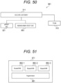
- Fig. 20 illustrates a configuration example of an information processing system 301 illustrating an example of a system architecture of the vehicle 1.
- the information processing system 301 is a system adopting a domain-type E/E (electrical/electronic) architecture.
- DC three domain controllers (DC), an ePWT (e-PoWer) domain controller (DC) 321, an ADAS domain controller (DC) 331, and an HMI + body domain controller (DC) 341 are connected to a secure gateway 311 via a network. Then, the information processing system 301 is divided into three domains D1 to D3 for each DC.
- DC three domain controllers
- ePWT e-PoWer domain controller
- DC ADAS domain controller
- DC HMI + body domain controller
- the ePWT DC 321 controls transfer and processing of data in the domain D1 including components and control components of the powertrain of the vehicle 1.
- a front electric drive unit (EDU) 322, a rear EDU 323, a charger ECU 324, an electric power steering (EPS) ECU 325, a brake ECU 326, a damper ECU 327, and the like are connected to the ePWT DC 321 via a network.
- the front EDU 322 is a unit that drives the front wheel of the vehicle 1.
- the rear EDU 323 is a unit that drives rear wheels of the vehicle 1.
- the charger ECU 324 controls a battery charger for driving the front EDU 322, the rear EDU 323, and the like.
- the EPS ECU 325 controls electric power steering of the vehicle 1.
- the brake ECU 326 controls a brake of the vehicle 1.
- the damper ECU 327 controls a damper of the vehicle 1.
- the ADAS DC 331 controls transfer and processing of data in the domain D2 including components that implement the ADAS of the vehicle 1.
- a radar 52, a LiDAR 53, a camera 332, a USS (ultrasonic sensor) ECU 333, a GNSS ECU 334, a data logger 335, and the like are connected to the ADAS DC 331 via a network.
- the camera 332 includes, for example, among the cameras 51 of the vehicle 1, cameras other than the camera 51SL4, the camera 51SR4, and the camera 51BC2 for the CMS.
- the USS ECU 333 controls the ultrasonic sensor 54.
- the GNSS ECU 334 controls the GNSS reception unit 24 and the like.
- the data logger 335 records data related to the processing of the ADAS.
- the HMI + body DC 341 controls transfer and processing of data in the domain D3 including components that realize the HMI of the vehicle 1 and components and control components of the body system of the vehicle 1.
- the door controller 342, the wiper controller 343, the seat controller 344, the display units 231CL to 231CR of the central portion 231C of the center display 231, the tablet terminal 235L, the tablet terminal 235R, the interface 345, and the like are connected to the HMI + body DC 341 via a network.
- a CMS 349 is connected to the HMI + body DC 341.
- the door controller 342 controls the doors 121FL to 121BR of the vehicle 1.
- the wiper controller 343 controls the wiper of the vehicle 1.
- the seat controller 344 controls, for example, positions and postures of the driver's seat 201, the passenger seat 202, the back seat 203L, and the back seat 203R.
- the CMS 346 includes, for example, components and control components of the CMS.
- the CMS 349 includes, for example, a camera 51SL4, a camera 51SR4, a camera 51BC2, and a display unit 231LL of the left end portion 231L and a display unit 231RR of the right end portion 231R of the center display 231.
- a telematics computing unit (TCM) 312 that performs communication with the outside is connected to the secure gateway 311.
- Fig. 21 illustrates a specific configuration example of portions mainly related to the CMS 349, the camera module 122L, and the camera module 122R in the information processing system 301.
- the ADAS DC 331, the HMI + body DC 341, and a ToF ECU 361 are connected to the secure gateway 311.
- the secure gateway 311, the ADAS DC 331, the HMI + body DC 341, and the ToF ECU 361 are connected via, for example, Ethernet.
- the ADAS DC 331 is connected with the cameras 51SL1 to 51SL3 included in the camera module 122L, the cameras 51SR1 to 51SR3 included in the camera module 122R, the camera 51BC1, the radar 52BC, and the LiDAR 53B.
- a camera 101L and a camera 101R configured by a ToF camera are connected to the ToF ECU 361.
- the CMS ECU 362, the display units 231CL to 231CR of the center display 231, and a sound amplifier 363 are connected to the HMI + body DC 341.
- the HMI + body DC 341 and the CMS ECU 362 are connected via, for example, a USB cable.
- the camera 51SL4 included in the camera module 122L, the camera 51SR4 included in the camera module 122R, and the display unit 231LL and the display unit 231RR of the center display 231 are connected to the CMS ECU 362. That is, in the camera module 122L, the cameras 51SL1 to 51SL3 are connected to the ADAS DC 331 and belong to the domain D2, and the camera 51SL4 is connected to the HMI + body DC 341 via the CMS ECU 362 and belongs to the domain D3.
- the cameras 51SR1 to 51SR3 are connected to the ADAS DC 331 and belong to the domain D2, and the camera 51SR4 is connected to the HMI + body DC 341 via the CMS ECU 362 and belongs to the domain D3.
- a speaker 364 is connected to the sound amplifier 363.
- the camera 51SL1 images an oblique front left of the vehicle 1.
- the camera 51SL2 includes a fisheye camera, and images the left direction of the vehicle 1.
- the camera 51SL3 images the left diagonal rear of the vehicle 1.
- the camera 51SR1 images the diagonally right front of the vehicle 1.
- the camera 51SR2 includes a fisheye camera, and images the right direction of the vehicle 1.
- the camera 51SR3 images the right diagonal rear of the vehicle 1.
- the camera 51BC1 includes a fisheye camera, and images the rear of the vehicle 1.
- the radar 52BC performs sensing of the rear of the vehicle 1 as described above.
- the LiDAR 53B performs sensing of the rear of the vehicle 1.
- the ADAS DC 331 implements, for example, a part of the recognition unit 73 of the vehicle 1.
- the ADAS DC 331 recognizes an object outside the vehicle 1 on the basis of sensor data from the cameras 51SL1 to 51SL3, the cameras 51SR1 to 51SR3, the camera 51BC1, the radar 52BC, and the LiDAR 53B.
- the ADAS DC 331 supplies data indicating the recognition result to another domain or the like via the secure gateway 311.
- the ToF ECU 361 realizes, for example, a part of the recognition unit 73 of the vehicle 1.
- the ToF ECU 361 recognizes the posture, movement, and the like of the driver on the basis of the image of the camera 101L.
- the ToF ECU 361 recognizes the posture, movement, and the like of the passenger on the passenger seat 202 on the basis of the image of the camera 101R.
- the ToF ECU 361 supplies data indicating a recognition result to another domain or the like via the secure gateway 311.
- the camera 51SL4 images the left diagonal rear of the vehicle 1.
- the camera 51SR4 images the right diagonal rear of the vehicle 1.
- the CMS ECU 362 controls the CMS.
- the CMS ECU 362 is a part of the function of the HMI 31, and implements a display control unit that controls the display of the display unit 231LL and the display unit 231RR.
- the CMS ECU 362 controls display of an image by the display unit 231LL of the camera 51SL4.
- the CMS ECU 362 controls display of the image of the camera 51SR4 by the display unit 231RR.
- the CMS ECU 362 controls display of the visual effect by the display unit 231LL and the display unit 231RR based on the object recognition result by the ADAS DC 331.
- the HMI + body DC 341 realizes a display control unit that controls the display of the display unit 231CL to the display unit 231CR of the center display 231.
- the speaker 364 includes, for example, the speakers 236FL to 236BR and the seat speakers 237 to 239R.
- the sound amplifier 363 amplifies various sounds output from the speaker 364.
- the HMI + body DC 341 is, for example, a part of the function of the HMI 31, and realizes a sound control unit that controls output of various sounds from the speaker 364.
- the vehicle 1 by adopting the domain-type E/E architecture, it is possible to suppress complication of the information processing system 301 and to further simplify the information processing system. As a result, the number of components and wiring in the vehicle can be reduced.
- the display control unit which is a part of the function of the HMI 31 displays an image based on the image of the camera 51SL4 on the display unit 231LL. More specifically, the display control unit sets the display range in the image of the camera 51SL4, and causes the display unit 231LL to display the image within the set display range.
- the recognition unit 73 performs object recognition on the basis of sensor data or the like from the cameras 51SL1 to 51SL3, the cameras 51SR1 to 51SR3, the camera 51BC1, the radar 52BC, and the LiDAR 53B, and recognizes an object outside the vehicle 1.
- the display control unit controls the display of the display unit 231LL on the basis of the recognition result of the object, the state of the vehicle 1, and the like.
- Fig. 22 illustrates a display example of the display unit 231LL at the normal time.
- a part of the body of the vehicle 1 a vehicle 401 that is a following vehicle traveling in the left adjacent lane on the left rear of the vehicle 1, and a road surface 402 are displayed.
- a bar 403 which is a vertically long belt-shaped visual effect, is displayed superimposed on the left end of the display unit 231LL as indicated by hatching in Fig. 23 .
- the bar 403 is displayed, for example, in a case where the vehicle 401 is within the range displayed on the display unit 231LL and the distance to the vehicle 1 is within a predetermined range.
- the color of the bar 403 is a conspicuous color, for example, yellow.
- the display mode such as the color, brightness, shape, blinking pattern, and movement of the bar 403 is not limited to this example, and can be arbitrarily changed.
- the display mode of the bar 403 changes according to the risk level.
- the blinking speed of the bar 403 changes according to the risk level. For example, as the absolute speed of the vehicle 401 or the relative speed with respect to the vehicle 1 increases, the blinking speed of the bar 403 increases. For example, as the vehicle 401 approaches, in other words, the distance between the vehicle 401 and the vehicle 1 becomes shorter, the blinking speed of the bar 403 becomes faster. Note that, for example, a warning sound may be emitted in synchronization with the blinking of the bar 403.
- the timing at which the bar 403 is displayed is advanced. That is, the bar 403 is displayed from the time when the vehicle 401 is located farther from the vehicle 1.
- the display control unit controls the range of the image to be displayed on the display unit 231LL in accordance with the operation of the direction indicator.
- Fig. 26 illustrates an example in which the range of the image to be displayed on the display unit 231LL is changed in accordance with the operation of the direction indicator in the left direction.
- a and B of Fig. 26 illustrate examples of images captured by the camera 51SL4.
- vehicles 421-1 to 421-4 and the like traveling in the left lane of the vehicle 1 are shown.
- the image in an area A21a in A of Fig. 26 is extracted, and the image in an area A22a is displayed on the display unit 231LL.
- the area A22a includes the vehicles 421-2 to 421-4 and does not include the vehicle 421-1.
- the driver when turning on the left direction indicator, the driver can check the situation of the lane on the left side of the vehicle 1 in a wider range. As a result, the driver can change lanes or turn left more safely.
- an icon, a frame, or the like indicating zooming out may be displayed on the display unit 231LL.
- the area A23L is an area surrounded by points P22L to P26L on the left side of the vehicle 1. Specifically, a left end point of the vehicle 1 corresponding to the same position as the driver's eyes in the front-rear direction of the vehicle 1 is set as a reference point P21L.
- the point P22L is a point 4 m behind the reference point P21L.
- the point P23L is a point 60 m behind the reference point P21L.
- the point P24L is a point 1 m away from the point P22L in the left direction.
- the point P25L is a point 20 m behind the reference point P21L and 4 m away to the left.
- the point P26L is a point 60 m behind the reference point P21L and 4 m away to the left.
- the area A23R is an area surrounded by points P22R to P26R on the right side of the vehicle 1. Specifically, a right end point of the vehicle 1 corresponding to the same position as the driver's eyes in the front-rear direction of the vehicle 1 is defined as a reference point P21R.
- the point P22R is a point 4 m behind the reference point P21R.
- the point P23R is a point 60 m behind the reference point P21R.
- the point P24R is a point separated 1 m rightward from the point P22R.
- the point P25R is a point 20 m behind the reference point P21R and 4 m away to the right.
- the point P25R is a point 60 m behind the reference point P21R and 4 m away to the right.
- the area A23C is a region that is 60 m or more away rearward from the position of the driver's eyes of the vehicle 1 and has a width of 20 m centered on the center in the left-right direction of the vehicle 1.
- the display range of the display unit 231LL is changed according to the operation of the direction indicator in the left direction, the display range is changed so as to always include the area A23L.
- the display unit 231RR of the center display 231 also controls the similar display range according to the operation of the direction indicator in the right direction. Furthermore, the display range of the display unit 231RR is changed so that the area A23R is always included.
- Fig. 28 illustrates an example in which the display range of the display unit 231LL is changed on the basis of the shift position of the vehicle 1.
- a and B of Fig. 28 illustrate examples of images captured by the camera 51SL4.
- a vehicle 441-1 and a vehicle 441-2 parked side by side on the left and right of the vehicle 1 are shown.
- the image in an area A31a in A of Fig. 28 is extracted, and the image in an area A32a is displayed on the display unit 231LL.
- the display range of the display unit 231RR of the center display 231 is changed similarly to the display unit 231LL on the basis of the shift position of the vehicle 1.
- the driver can check the situation on the left diagonal rear side of the vehicle 1 in a wider range. As a result, the driver can park the vehicle 1C more safely.
- the driver can set the display ranges of the display unit 231LL and the display unit 231RR by operating the operation screen displayed on the console display 232 illustrated in Fig. 13 and the like.
- the driver can individually move the display range of the display unit 231LL and the display range of the display unit 231RR, or individually set a zoom ratio (Zoom Factor) for each display range.
- zoom Factor Zoom Factor
- the display range can be set within a settable range A41 illustrated in Fig. 29 .
- Fig. 29 portions corresponding to those in Fig. 26 are denoted by the same reference numerals, and the description thereof will be omitted as appropriate.
- the size of the extraction range A42 extracted for display from the captured image is set on the basis of the set zoom ratio. That is, zoom-in (reduction) and zoom-out (expansion) of the extraction range A42 are performed on the basis of the zoom ratio. Then, an image within a predetermined display range A42 within the extraction range A43 is displayed on the display unit 231LL.
- the display range A43 can be moved within the settable range A41.
- the settable range A41 is set to a range in which an area A23L is included in the display range A43.
- a warning is issued to the driver.
- a warning message is displayed on the display unit 231LL, and a warning sound is output.
- the movement range of the display range A43 may be limited so that the display range A43 does not go out of the settable range A41 regardless of the operation of the driver.
- the driver can move the display range A43 to his/her desired position or zoom in or out the display range A43 within a range including the area A23L. Furthermore, the driver can adjust the display range A43 without diverting the line-of-sight, for example, by moving or clicking a finger on the console display 232 while maintaining the driving posture.
- the driver can change the range seen through the side mirror by bringing his/her face close to the side mirror and looking into the side mirror. For example, the driver sometimes checks the presence or absence of an obstacle on the ground around the vehicle by looking into the side mirror during parking or the like.
- the display area of the display unit 231LL can be similarly changed by the driver moving his/her face close to the display unit 231LL and looking into the display unit.
- the DMS 30 detects the position and orientation of the head of the driver by performing skeleton recognition or the like of the driver on the basis of the image of the camera 101L.
- the DMS 30 detects an angle at which the driver looks into the display unit 231LL in a case where the driver recognizes the action of looking into the display unit 231LL on the basis of the position and orientation of the head of the driver.
- the display control unit controls the display range of the display unit 231LL on the basis of the angle at which the driver looks into the display unit 231LL.
- Fig. 30 illustrates a display range of the display unit 231LL before the driver looks in.
- a part of the body of the vehicle 1 is displayed in the lower right corner of the display unit 231LL.
- a part of the upper portion of an object 461 on the left rear of the vehicle 1 is displayed.
- a line 462 which is a band-shaped visual effect indicating a region of the ground within a predetermined range around the vehicle 1, is displayed in a superimposed manner and blinks.
- the driver can quickly recognize an object with which the vehicle 1 may collide or come into contact, and move the vehicle 1 while avoiding the recognized object.
- Fig. 32 illustrates a display range of the display unit 231LL before the driver looks in.
- a part of the body of the vehicle 1 is displayed at the right end of the display unit 231LL.
- a part of a left rear vehicle 481 is displayed on the upper left of the display unit 231LL.
- a parking line 482 is displayed between the vehicle 1 and the vehicle 481.
- the upper end of the object 483 is displayed on the left of the vehicle 1 and at the lower end of the display unit 231LL.
- the display range of the display unit 231LL is zoomed out as described above with reference to Fig. 28 .
- the display range of the display unit 231LL is widened, and the range in which the vehicle 1, the vehicle 481, and an object 483 are displayed is widened.
- the display range of the display unit 231LL moves downward as illustrated in Fig. 34 .
- the entire object 483 is displayed on the display unit 231LL.
- the driver can park the vehicle 1 while reliably avoiding the object 483.
- the display range moves similarly to the display unit 231LL even in a case where the driver looks into the display unit 231RR of the center display 231.
- the display range does not change even if the driver looks into the display unit 231LL and the display unit 231RR.
- the display range of the digital rear mirror 234 moves.
- the DMS 30 detects the movement of the left hand of the driver by performing skeleton recognition or the like of the driver on the basis of the image of the camera 101L.
- the recognition unit 73 detects an object around the door 121FL of the driver's seat 201 outside the vehicle 1 on the basis of images of the camera 51SL2, the camera 51SL3, and the like. Then, in a case where an object is detected in a predetermined range around the door 121FL of the driver's seat 201, in a case where the driver performs an operation of opening the door 121FL, for example, in a case where the left hand of the driver touches the door opener 216FL of the door 121FL, the display unit 231LL displays a warning.
- Fig. 35 illustrates a display example of the display unit 231LL before the left hand of the driver touches the door opener 216FL.
- a part of the body of the vehicle 1 is displayed at the right end of the display unit 231LL.
- the display unit 231LL displays a warning as indicated by hatching in Fig. 37 .
- a bar 502 which is a vertically long belt-shaped visual effect, is displayed in a superimposed manner and blinks.
- the color of the bar 502 is a conspicuous color, for example, yellow.
- a warning sound may be output.
- the body system control unit 84 may increase the torque of the door 121FL to make it difficult to open the door 121FL.
- the display unit 231RR on the passenger seat 202 side may display a similar warning.
- the display control unit displays contents corresponding to the situation on the display unit 231CL on the basis of at least one of the situation of the vehicle 1, the situation around the vehicle 1, or the situation of the passenger.
- the light control unit 85 lights or flashes the illumination 207 in a pattern according to the situation on the basis of at least one of the situation of the vehicle 1, the situation around the vehicle 1, or the situation of the passenger.
- the light emission pattern of the illumination 207 is defined by, for example, at least one of a color, brightness, a blinking pattern, light movement, or a light emission area.
- the DMS 30 performs recognition processing of the driver on the basis of at least one of the image of the camera 101L or the image of the camera 102. Then, the display unit 231CL and the illumination 207 provide notification that the driver is recognized.
- Fig. 38 illustrates a state of the display unit 231CL and the illumination 207 before the driver is recognized.
- the state of the vehicle 1 is displayed on the display unit 231CL. Specifically, a shift position, a charge amount, a speed, a cruisable distance, and the like are displayed.
- Fig. 39 illustrates states of the display unit 231CL and the illumination 207 when the driver is recognized.
- the display unit 231CL displays the recognized image and name of the driver, and a message for the driver. Thereafter, the display unit 231CL returns to the state of Fig. 38 .
- the illumination 207 is turned on in a predetermined pattern.
- a plurality of short white light bands moves so as to flow in a predetermined pattern on the illumination 207.
- the driver is reliably notified that the vehicle 1 has recognized the driver.
- the body system control unit 84 may set the position and angle of the driver's seat 201, the position and angle of the steering wheel 206, and the like on the basis of the recognized physique of the driver, preference of the driver set in advance, or the like. As a result, a driving position suitable for the recognized driver is set.
- the display control unit may adjust the display position of the display unit 231CL of the center display 231 on the basis of the recognized position of the driver's eyes, the position and angle of the steering wheel 206, and the like.
- the display range of the display unit 231CL is set at an easily viewable position without being blocked by the steering wheel 206 according to the recognized driver.
- the display unit 231CL and the illumination 207 provide notification that the preparation for the automated driving is completed.
- Fig. 40 illustrates states of the display unit 231CL and the illumination 207 when preparation for automated driving is completed.
- an icon 601 indicating that preparation for automated driving is completed is displayed in addition to the display content of Fig. 39 . Note that, to the left of the icon 601, the speed limit of the road on which the vehicle 1 is traveling is displayed.
- the illumination 207 is turned on in a predetermined pattern.
- a plurality of short white light bands moves so as to flow in a predetermined pattern on the illumination 207.
- the driver can surely recognize that the preparation for the automated driving is completed.
- the display unit 231CL and the illumination 207 provide notification of the start of the automated driving.
- Fig. 41 illustrates states of the display unit 231CL and the illumination 207 at the start of the automated driving.
- the illumination 207 is turned on in a predetermined pattern. For example, a plurality of short white light bands gradually changes to blue while moving so as to flow in a predetermined pattern on the illumination 207. Finally, the entire illumination 207 is lit in blue, and the state of being lit in blue is maintained during the automated driving.
- the driver can surely recognize that the automated driving is started. Furthermore, by turning on the illumination 207, a passenger other than the driver can surely recognize that the automated driving is started.
- Fig. 42 illustrates states of the display unit 231CL and the illumination 207 in a case where the vehicle 1 changes lanes to the right lane during automated driving.
- the display unit 231CL displays guidance information 603 including an animation for providing notification of the execution and direction of the lane change so as to be superimposed on the image in front of the vehicle 1.
- a predetermined blinking range A101 on the right side of the illumination 207 blinks in blue.
- blinking range A101 rotates in the opposite direction (counterclockwise) in accordance with the rotation angle of the steering wheel 206.
- blinking range A101 rotates in the opposite direction (clockwise) in accordance with the rotation angle of the steering wheel 206.
- blinking range A101 is maintained at a constant position as viewed from the outside without rotating together with the steering wheel 206. Then, after the rotation angle of the steering wheel 206 returns to 0 degrees, the entire illumination 207 lights blue similarly to before the lane change.
- the driver can recognize in advance that the vehicle 1 changes lanes.
- the guidance information 603 is displayed superimposed on the display unit 231CL, and the predetermined blinking range on the left side of the illumination 207 blinks in blue.
- Fig. 43 illustrates states of the display unit 231CL and the illumination 207 in a case where a dangerous state is detected around the vehicle 1.
- a message 611 and an icon 612 indicating the detected state, the coping method, and the like are displayed.
- a warning sound is output in accordance with blinking of the blinking range A111.
- the DMS 30 can recognize the shape and position of both ears of the passenger of the back seat 203L on the basis of the image of the ToF camera provided in the tablet terminal 235L. Therefore, the sound control unit can appropriately set the sound image, the sound field, the volume, and the like for the passenger by controlling the seat speaker 239L and the like of the back seat 203L on the basis of the positions and shapes of both ears of the passenger.
- the DMS 30 can recognize the shape and position of both ears of the passenger on the back seat 203R on the basis of the image of the ToF camera provided in the tablet terminal 235R. Therefore, the sound control unit can appropriately set the sound image, the sound field, the volume, and the like for the passenger by controlling the seat speaker 239R and the like of the back seat 203R on the basis of the positions and shapes of both ears of the passenger.
- the vehicle 1 can individually output sound to the occupant on each seat, and can individually control a sound image, a sound field, a volume, and the like.
- Figs. 44 to 47 illustrate an example of a method of controlling a warning sound for calling attention to a vehicle 701 approaching from the left rear.
- Fig. 44 illustrates a sound field A151 at the start of output of the warning sound.
- the apex of the conical sound field A151 indicates the position of the virtual sound source.
- the direction in which the cone spreads from the apex of the sound field A151 indicates the direction in which the sound field spreads.
- the direction of sound field A151 is set to be substantially equal to the direction in which the head of the driver of vehicle 1 is viewed from vehicle 701. Furthermore, the virtual sound source of the warning sound is set at a position away from the head of the driver in the direction of the vehicle 701 by a predetermined distance.
- the configuration of the information processing system 301 in Figs. 20 and 21 can be appropriately changed.
- modification examples of the system architecture of the vehicle 1 will be described with reference to Figs. 48 to 50 .
- modification examples of the configuration of the domain controller (domain) of the information processing system 301 will be described. Note that, in Figs. 48 to 50 , illustration of a configuration under the domain controller is omitted.
- the information processing system 801 is provided with an HMI DC 811 and a body DC 812 instead of the HMI + body DC 341 as compared with the information processing system 301. That is, the HMI + body DC 341 is divided into the HMI DC 811 and the body DC 812. Therefore, the domain D3 in Fig. 20 is divided into the domain of the HMI system and the domain of the body system.
- Fig. 49 illustrates a configuration example of an information processing system 821 that is a second modification example of the information processing system 301. Note that, in the figure, portions corresponding to those of the information processing system 801 in Fig. 48 are denoted by the same reference signs, and description thereof will be omitted as appropriate.
- the information processing system 821 is provided with an ADAS + HMI DC 831 instead of the ADAS DC 331 and the HMI DC 811. That is, the ADAS DC 331 and the HMI DC 811 are integrated. Therefore, the ADAS-based domain D2 ( Fig. 20 ) and the HMI-based domain are integrated.
- Fig. 50 illustrates a configuration example of an information processing system 841 that is a third modification example of the information processing system 301. Note that, in the figure, portions corresponding to those of the information processing system 801 in Fig. 48 are denoted by the same reference signs, and description thereof will be omitted as appropriate.
- the information processing system 841 is provided with an ADAS + HMI + body DC 851 instead of the ADAS DC 331, the HMI DC 811, and the body DC 812. That is, the ADAS DC 331, the HMI DC 811, and the body DC 812 are integrated. Therefore, the domain D2 and the domain D3 in Fig. 20 are integrated.
- the ADAS + HMI + body DC 851 can be realized by one piece of hardware 871 using a virtualization technology, for example, as illustrated in Fig. 51 .
- the functions corresponding to the ADAS DC 313, the HMI DC 811, and the body DC 812 may be implemented by a guest virtual machine (VM) 882-1 to a guest VM 882-3 operating on the hypervisor 881 in the hardware 871.
- VM guest virtual machine
- Fig. 52 illustrates a configuration example of an information processing system 901 that is a modification example of the information processing system 301 in Fig. 21 . Note that portions corresponding to those of the information processing system 301 in Fig. 21 are denoted by the same reference numerals, and the description thereof will be omitted as appropriate.
- the information processing system 901 is different from the information processing system 301 in Fig. 21 in that a video splitter 911 is provided.
- the camera 51SL2, the camera 51SR2, and the camera 51BC1 are connected to the video splitter 911.
- the video splitter 911 branches the image signals of the camera 51SL2, the camera 51SR2, and the camera 51BC1 into image signals of two systems, and supplies the image signals to the ADAS DC 331 and the HMI + body DC 341. Therefore, the camera 51SL2, the camera 51SR2, and the camera 51BC1 are connected to the ADAS DC 331 and the HMI + body DC 341 via the video splitter 911. That is, the camera 51SL2, the camera 51SR2, and the camera 51BC1 belong to both the domain D2 and the domain D3 illustrated in Fig. 20 .
- the camera 51FC1 is also connected to the ADAS DC 331 and the HMI + body DC 341 via the video splitter 911.
- the HMI + body DC 341 generates an image for surround view on the basis of the images of the camera 51FC1, the camera 51SL2, the camera 51SR2, and the camera 51BC1.
- the HMI + body DC 341 displays the image for surround view on one or more of the display units 231CL to 231CR of the center display 231.
- Fig. 53 illustrates a configuration example of the video splitter 911. Note that although Fig. 53 illustrates only a circuit related to the camera 51SL2, a similar circuit is provided for the other cameras 51FC1, 51SR2, and 51BC1.
- the video splitter 911 includes an input terminal 921, a deserializer 922, a serializer 923-1, a serializer 923-2, an output terminal 924-1, and an output terminal 924-2.
- the deserializer 922 is connected to the input terminal 921, the serializer 923-1, and the serializer 923-2.
- the serializer 923-1 is connected to the output terminal 924-1.
- the serializer 923-2 is connected to the output terminal 924-2.
- the image signal of the camera 51SL2 is input to the deserializer 922 via the input terminal 921.
- the deserializer 922 branches the image signal and supplies the image signal to the serializer 923-1 and the serializer 923-2.
- the serializer 923-1 converts the image signal into a serial signal and supplies the serial signal to the ADAS DC 331 via the output terminal 924-1.
- the serializer 923-2 converts the image signal into a serial signal and supplies the serial signal to the HMI + body DC 341 via the output terminal 924-2.
- a fisheye camera 941 in Fig. 54 may be used for the camera 51FC1, the camera 51SL2, the camera 51SR2, and the camera 51BC1.
- the fisheye camera 941 includes a lens 951, a serializer 952, an output terminal 953-1, and an output terminal 953-2. Note that illustration of a circuit that captures and processes an image is omitted.
- the fisheye camera 941 branches an image signal obtained by imaging by the serializer 952.
- the branched image signal is supplied to the ADAS DC 331 via the output terminal 953-1, and is supplied to the HMI + body DC 341 via the output terminal 953-2.
- the system architecture can be flexibly changed.
- the system architecture for example, it is possible to suppress complication of a system including each camera and to make the system simpler.
- the number of cameras of the camera module 122L can be changed.
- the camera 51SL1 and the camera 51SL2 can be integrated into one wide-angle and high-resolution camera.
- the camera 51SL2 and the camera 51SL3 can be integrated into one wide-angle and high-resolution camera.
- the camera 51SL3 and the camera 51SL4 can be integrated into one wide-angle and high-resolution camera.
- the cameras 51SL1 to 51SL3 can be integrated into one wide-angle and high-resolution camera.
- the cameras 51SL1 to 51SL4 can be integrated into one high-resolution fisheye camera.
- one of the camera 51SL2 and the camera 51SR2 including a fisheye camera can be omitted.
- one of the images of the digital outer mirror displayed on the display unit 231LL and the display unit 231RR of the center display 231 may be displayed at the central portion 231C.
- the present technology can also be applied to a right-handed vehicle.
- the present technology is applied to a right steering wheel vehicle, the above-described layout of the outside and inside of the vehicle is appropriately changed in accordance with the right steering wheel.
- the present technology can also be applied to, for example, a moving device in which a passenger performs automated driving without driving.
- a moving device in which a passenger performs automated driving without driving.
- the above-described distinction between the driver's seat 201 and the passenger seat 202 is eliminated, and the above-described various displays are arranged in front of the seat in the moving device or the like.
- a display range or the like of an image displayed on the display is changed on the basis of a line-of-sight direction, a posture, or the like of a person sitting on a predetermined seat.
- the above-described series of processing can be executed by hardware or software.
- a program constituting the software is installed in a computer (For example, the processor 21 or the like).
- the program executed by the computer may be a program in which processing is performed in time series in the order described in the present specification, or may be a program in which processing is performed in parallel or at necessary timing such as when a call is made.
- a system means a set of a plurality of components (devices, modules (parts), etc.), and it does not matter whether or not all the components are in the same housing. Therefore, a plurality of devices housed in separate housings and connected via a network and one device in which a plurality of modules is housed in one housing are both systems.
- the present technology can have a configuration of cloud computing in which one function is shared and processed in cooperation by a plurality of devices via a network.
- each step described in the above-described flowchart can be executed by one device or can be shared and executed by a plurality of devices.
- the present technology can also have the following configurations.
Landscapes
- Engineering & Computer Science (AREA)
- Multimedia (AREA)
- Signal Processing (AREA)
- Mechanical Engineering (AREA)
- Traffic Control Systems (AREA)
Applications Claiming Priority (2)
| Application Number | Priority Date | Filing Date | Title |
|---|---|---|---|
| JP2020178137 | 2020-10-23 | ||
| PCT/JP2021/037305 WO2022085487A1 (ja) | 2020-10-23 | 2021-10-08 | カメラモジュール、情報処理システム、情報処理方法、及び、情報処理装置 |
Publications (2)
| Publication Number | Publication Date |
|---|---|
| EP4236304A1 true EP4236304A1 (de) | 2023-08-30 |
| EP4236304A4 EP4236304A4 (de) | 2024-04-03 |
Family
ID=81290419
Family Applications (1)
| Application Number | Title | Priority Date | Filing Date |
|---|---|---|---|
| EP21882628.7A Withdrawn EP4236304A4 (de) | 2020-10-23 | 2021-10-08 | Kameramodul, informationsverarbeitungssystem, informationsverarbeitungsverfahren und informationsverarbeitungsvorrichtung |
Country Status (6)
| Country | Link |
|---|---|
| US (1) | US12552320B2 (de) |
| EP (1) | EP4236304A4 (de) |
| JP (1) | JP7732463B2 (de) |
| KR (1) | KR20230091870A (de) |
| CN (1) | CN116171239A (de) |
| WO (1) | WO2022085487A1 (de) |
Cited By (1)
| Publication number | Priority date | Publication date | Assignee | Title |
|---|---|---|---|---|
| WO2025119644A1 (en) * | 2023-12-05 | 2025-06-12 | Valeo Schalter Und Sensoren Gmbh | Drive recorder system |
Families Citing this family (5)
| Publication number | Priority date | Publication date | Assignee | Title |
|---|---|---|---|---|
| USD1066364S1 (en) * | 2021-01-08 | 2025-03-11 | Sony Group Corporation | Display screen or portion thereof with animated graphical user interface |
| DE102021111200A1 (de) * | 2021-04-30 | 2022-11-03 | Bayerische Motoren Werke Aktiengesellschaft | Geräteträger für ein Fahrzeug |
| JP2023047495A (ja) * | 2021-09-27 | 2023-04-06 | キヤノン株式会社 | 移動体、画像処理方法、およびコンピュータプログラム |
| US12597217B2 (en) * | 2023-06-23 | 2026-04-07 | Valeo Comfort And Driving Assistance | Methods and systems for augmented reality in automotive applications |
| TW202547730A (zh) * | 2024-06-07 | 2025-12-16 | 巨鎧精密工業股份有限公司 | 電子式後視鏡系統 |
Family Cites Families (55)
| Publication number | Priority date | Publication date | Assignee | Title |
|---|---|---|---|---|
| DE2943941A1 (de) * | 1979-10-31 | 1981-05-14 | Bayerische Motoren Werke AG, 8000 München | Kraftfahrzeug mit einem den toten winkel erfassenden zusatzspiegel |
| JP2001114048A (ja) | 1999-10-20 | 2001-04-24 | Matsushita Electric Ind Co Ltd | 車載運転支援情報表示装置 |
| JP4537537B2 (ja) | 2000-05-25 | 2010-09-01 | パナソニック株式会社 | 運転支援装置 |
| JP3372944B2 (ja) * | 2000-07-19 | 2003-02-04 | 松下電器産業株式会社 | 監視システム |
| WO2002007443A1 (en) * | 2000-07-19 | 2002-01-24 | Matsushita Electric Industrial Co., Ltd. | Monitoring system |
| JP2009017020A (ja) * | 2007-07-02 | 2009-01-22 | Nissan Motor Co Ltd | 画像処理装置及び表示画像生成方法 |
| EP2119596B1 (de) | 2008-05-16 | 2012-01-04 | SMR Patents S.à.r.l. | Bilderfassendes System für Fahrzeuge und Rückspiegelanordnung mit einem solchen system |
| US9036026B2 (en) * | 2009-06-12 | 2015-05-19 | Magna Electronics | Scalable integrated electronic control unit for vehicle |
| KR100959347B1 (ko) * | 2010-02-24 | 2010-05-20 | 조성호 | 자동차의 좌우후방 시야확보 장치 |
| JP2012156672A (ja) | 2011-01-25 | 2012-08-16 | Clarion Co Ltd | 車両周辺監視装置 |
| WO2013067082A1 (en) * | 2011-11-01 | 2013-05-10 | Magna Mirrors Of America, Inc. | Vision system with door mounted exterior mirror and display |
| US10946798B2 (en) * | 2013-06-21 | 2021-03-16 | Magna Electronics Inc. | Vehicle vision system |
| US10908417B2 (en) * | 2013-09-19 | 2021-02-02 | Magna Electronics Inc. | Vehicle vision system with virtual retinal display |
| US10099615B2 (en) * | 2014-09-29 | 2018-10-16 | Ambarella, Inc. | All-round view monitoring system for a motor vehicle |
| US10127463B2 (en) * | 2014-11-21 | 2018-11-13 | Magna Electronics Inc. | Vehicle vision system with multiple cameras |
| US20160159281A1 (en) * | 2014-12-04 | 2016-06-09 | Hyundai Mobis Co., Ltd. | Vehicle and control method thereof |
| WO2016094801A1 (en) * | 2014-12-12 | 2016-06-16 | Hoyda Serge B | System and process for viewing in blind spots |
| US11124116B2 (en) * | 2014-12-12 | 2021-09-21 | Serge B. HOYDA | System and process for viewing in blind spots |
| US20160191795A1 (en) * | 2014-12-30 | 2016-06-30 | Alpine Electronics, Inc. | Method and system for presenting panoramic surround view in vehicle |
| EP3141926B1 (de) * | 2015-09-10 | 2018-04-04 | Continental Automotive GmbH | Automatisierte erkennung gefährlich abdriftender fahrzeuge durch fahrzeugsensoren |
| KR101850795B1 (ko) * | 2015-11-09 | 2018-04-20 | 엘지전자 주식회사 | 주차 수행 장치 및 차량 |
| US10523865B2 (en) * | 2016-01-06 | 2019-12-31 | Texas Instruments Incorporated | Three dimensional rendering for surround view using predetermined viewpoint lookup tables |
| US10694150B2 (en) * | 2016-04-12 | 2020-06-23 | Magna Electronics Inc. | Multi-camera vehicle vision system with distributed processing, data connection and power supply |
| JP6361988B2 (ja) | 2016-05-30 | 2018-07-25 | マツダ株式会社 | 車両用表示装置 |
| WO2018008007A1 (en) * | 2016-07-08 | 2018-01-11 | Rodriguez Ortiz Miguel Angel | Vehicular camera system for improving a driver's visibility |
| US10829044B2 (en) * | 2016-08-08 | 2020-11-10 | Koito Manufacturing Co., Ltd. | Vehicle monitoring system using a plurality of cameras |
| US10380439B2 (en) | 2016-09-06 | 2019-08-13 | Magna Electronics Inc. | Vehicle sensing system for detecting turn signal indicators |
| JP2019206194A (ja) | 2016-09-29 | 2019-12-05 | 株式会社村上開明堂 | 車両用視認装置 |
| KR102551099B1 (ko) * | 2017-01-13 | 2023-07-05 | 엘지이노텍 주식회사 | 어라운드뷰 제공장치, 제공방법 및 이를 구비한 차량 |
| JP6730614B2 (ja) | 2017-02-28 | 2020-07-29 | 株式会社Jvcケンウッド | 車両用表示制御装置、車両用表示システム、車両用表示制御方法およびプログラム |
| US11463610B2 (en) * | 2017-05-10 | 2022-10-04 | Mobileye Vision Technologies Ltd. | Cross field of view for autonomous vehicle systems |
| KR101778624B1 (ko) * | 2017-05-16 | 2017-09-26 | (주)텔미전자 | 자율주행용 서라운드 카메라 시스템 |
| JP6815957B2 (ja) | 2017-09-13 | 2021-01-20 | 株式会社ミツバ | ドアミラー |
| JP2018197021A (ja) | 2017-05-23 | 2018-12-13 | 株式会社ミツバ | ドアミラー |
| JP7059522B2 (ja) * | 2017-06-09 | 2022-04-26 | ソニーグループ株式会社 | 制御装置、制御方法、プログラム及び撮像システム |
| US10812712B2 (en) * | 2018-04-23 | 2020-10-20 | Toyota Motor Engineering & Manufacturing North America, Inc. | Systems and methods for vehicle camera view activation |
| WO2020157901A1 (ja) | 2019-01-31 | 2020-08-06 | 三菱電機株式会社 | 運転支援装置 |
| JP7243478B2 (ja) * | 2019-06-24 | 2023-03-22 | トヨタ自動車株式会社 | 車両用情報記録装置 |
| US11341614B1 (en) * | 2019-09-24 | 2022-05-24 | Ambarella International Lp | Emirror adaptable stitching |
| US12522142B2 (en) * | 2019-10-23 | 2026-01-13 | Sony Group Corporation | Display system, display device, display method, and mobile apparatus |
| US12296740B2 (en) * | 2019-12-26 | 2025-05-13 | Sony Group Corporation | Vehicle |
| WO2021150369A1 (en) * | 2020-01-22 | 2021-07-29 | Nodar Inc. | Non-rigid stereo vision camera system |
| KR102327734B1 (ko) * | 2020-04-29 | 2021-11-17 | 삼성전기주식회사 | 차량용 카메라 시스템 및 그 동작 방법 |
| US11823395B2 (en) * | 2020-07-02 | 2023-11-21 | Magna Electronics Inc. | Vehicular vision system with road contour detection feature |
| WO2022014327A1 (ja) * | 2020-07-14 | 2022-01-20 | ソニーセミコンダクタソリューションズ株式会社 | 情報処理装置、情報処理方法、およびプログラム |
| EP4137926A4 (de) * | 2020-09-14 | 2024-01-10 | LG Electronics, Inc. | Bildverarbeitungsvorrichtung für ein fahrzeug und verfahren zur anzeige visueller informationen auf einer in einem fahrzeug enthaltenen anzeige |
| US11884216B2 (en) * | 2020-10-16 | 2024-01-30 | Magna Mirrors Of America, Inc. | Vehicular full mirror display system with auxiliary forward and rearward views |
| CN116670006A (zh) * | 2021-01-04 | 2023-08-29 | 索尼集团公司 | 信息处理设备、信息处理方法、程序、移动设备和信息处理系统 |
| JP7613313B2 (ja) * | 2021-08-04 | 2025-01-15 | トヨタ自動車株式会社 | 車両用表示装置、車両用表示方法及び車両用表示プログラム |
| JP2023046930A (ja) * | 2021-09-24 | 2023-04-05 | キヤノン株式会社 | カメラユニットの設置方法、移動体、画像処理システム、画像処理方法、およびコンピュータプログラム |
| WO2023127511A1 (ja) * | 2021-12-27 | 2023-07-06 | ソニーグループ株式会社 | 照明制御装置、照明制御方法、及び、車両 |
| WO2023127510A1 (ja) * | 2021-12-27 | 2023-07-06 | ソニーグループ株式会社 | 情報処理装置、情報処理方法、プログラム、及び、移動体 |
| US20250155258A1 (en) * | 2022-03-04 | 2025-05-15 | Sony Group Corporation | Information processing device, information processing method, and moving body |
| KR20240036193A (ko) * | 2022-09-13 | 2024-03-20 | 현대자동차주식회사 | 사이드 미러 및 그를 가지는 차량 |
| US12432460B2 (en) * | 2022-10-14 | 2025-09-30 | Motional Ad Llc | Cascade camera tuning |
-
2021
- 2021-10-08 JP JP2022556905A patent/JP7732463B2/ja active Active
- 2021-10-08 US US18/249,072 patent/US12552320B2/en active Active
- 2021-10-08 KR KR1020237011625A patent/KR20230091870A/ko active Pending
- 2021-10-08 WO PCT/JP2021/037305 patent/WO2022085487A1/ja not_active Ceased
- 2021-10-08 EP EP21882628.7A patent/EP4236304A4/de not_active Withdrawn
- 2021-10-08 CN CN202180070439.XA patent/CN116171239A/zh active Pending
Cited By (1)
| Publication number | Priority date | Publication date | Assignee | Title |
|---|---|---|---|---|
| WO2025119644A1 (en) * | 2023-12-05 | 2025-06-12 | Valeo Schalter Und Sensoren Gmbh | Drive recorder system |
Also Published As
| Publication number | Publication date |
|---|---|
| JPWO2022085487A1 (de) | 2022-04-28 |
| US12552320B2 (en) | 2026-02-17 |
| CN116171239A (zh) | 2023-05-26 |
| JP7732463B2 (ja) | 2025-09-02 |
| WO2022085487A1 (ja) | 2022-04-28 |
| US20230415652A1 (en) | 2023-12-28 |
| KR20230091870A (ko) | 2023-06-23 |
| EP4236304A4 (de) | 2024-04-03 |
Similar Documents
| Publication | Publication Date | Title |
|---|---|---|
| JP7852696B2 (ja) | 移動装置、情報処理装置、及び、情報処理方法 | |
| US12552320B2 (en) | Camera module, information processing system, information processing method, and information processing apparatus | |
| KR101895485B1 (ko) | 운전 보조 장치 및 그 제어 방법 | |
| JP7786398B2 (ja) | 情報処理装置、情報処理方法、プログラム、移動装置、及び、情報処理システム | |
| CN107891809A (zh) | 自动驻车辅助装置、提供自动驻车功能的方法以及车辆 | |
| CN107226027A (zh) | 显示装置及包括其的车辆 | |
| JP7647573B2 (ja) | 車両 | |
| US20240420385A1 (en) | Information processing apparatus, information processing method, program, and information processing system | |
| EP4404177A1 (de) | Fahrzeugsteuerungssystem, fahrzeugsteuerungsverfahren und programm | |
| WO2022201892A1 (en) | Information processing apparatus, information processing method, and program | |
| WO2023166982A1 (ja) | 情報処理装置、情報処理方法、及び、移動体 | |
| US20260045152A1 (en) | Information processing apparatus, information processing method, and program | |
| WO2024232244A1 (ja) | 情報処理装置、情報処理方法、およびプログラム | |
| WO2024232245A1 (ja) | 情報処理装置、情報処理方法、およびプログラム |
Legal Events
| Date | Code | Title | Description |
|---|---|---|---|
| STAA | Information on the status of an ep patent application or granted ep patent |
Free format text: STATUS: THE INTERNATIONAL PUBLICATION HAS BEEN MADE |
|
| PUAI | Public reference made under article 153(3) epc to a published international application that has entered the european phase |
Free format text: ORIGINAL CODE: 0009012 |
|
| STAA | Information on the status of an ep patent application or granted ep patent |
Free format text: STATUS: REQUEST FOR EXAMINATION WAS MADE |
|
| 17P | Request for examination filed |
Effective date: 20230513 |
|
| AK | Designated contracting states |
Kind code of ref document: A1 Designated state(s): AL AT BE BG CH CY CZ DE DK EE ES FI FR GB GR HR HU IE IS IT LI LT LU LV MC MK MT NL NO PL PT RO RS SE SI SK SM TR |
|
| DAV | Request for validation of the european patent (deleted) | ||
| DAX | Request for extension of the european patent (deleted) | ||
| A4 | Supplementary search report drawn up and despatched |
Effective date: 20240306 |
|
| RIC1 | Information provided on ipc code assigned before grant |
Ipc: H04N 23/90 20230101ALI20240229BHEP Ipc: B60R 1/27 20220101ALI20240229BHEP Ipc: B60R 1/26 20220101ALI20240229BHEP Ipc: B60R 1/25 20220101ALI20240229BHEP Ipc: B60R 1/24 20220101ALI20240229BHEP Ipc: B60R 1/20 20220101ALI20240229BHEP Ipc: H04N 7/18 20060101AFI20240229BHEP |
|
| STAA | Information on the status of an ep patent application or granted ep patent |
Free format text: STATUS: THE APPLICATION HAS BEEN WITHDRAWN |
|
| 18W | Application withdrawn |
Effective date: 20250430 |