EP4236441A1 - Datenübertragungsverfahren und -vorrichtung sowie vorrichtung - Google Patents
Datenübertragungsverfahren und -vorrichtung sowie vorrichtung Download PDFInfo
- Publication number
- EP4236441A1 EP4236441A1 EP21881898.7A EP21881898A EP4236441A1 EP 4236441 A1 EP4236441 A1 EP 4236441A1 EP 21881898 A EP21881898 A EP 21881898A EP 4236441 A1 EP4236441 A1 EP 4236441A1
- Authority
- EP
- European Patent Office
- Prior art keywords
- data packet
- user equipment
- uplink resource
- transmission
- physical layer
- Prior art date
- Legal status (The legal status is an assumption and is not a legal conclusion. Google has not performed a legal analysis and makes no representation as to the accuracy of the status listed.)
- Pending
Links
- 230000005540 biological transmission Effects 0.000 title claims abstract description 228
- 238000000034 method Methods 0.000 title claims abstract description 130
- 230000008569 process Effects 0.000 claims description 49
- 238000004590 computer program Methods 0.000 claims description 26
- 230000007246 mechanism Effects 0.000 description 11
- 230000006870 function Effects 0.000 description 7
- 238000010586 diagram Methods 0.000 description 6
- 230000000737 periodic effect Effects 0.000 description 6
- 230000011664 signaling Effects 0.000 description 5
- 230000009471 action Effects 0.000 description 4
- 238000004891 communication Methods 0.000 description 4
- 230000007774 longterm Effects 0.000 description 4
- 238000010295 mobile communication Methods 0.000 description 4
- 230000003287 optical effect Effects 0.000 description 4
- 230000009286 beneficial effect Effects 0.000 description 2
- 230000000694 effects Effects 0.000 description 2
- 238000005516 engineering process Methods 0.000 description 2
- 238000007726 management method Methods 0.000 description 2
- 230000001960 triggered effect Effects 0.000 description 2
- 239000000969 carrier Substances 0.000 description 1
- 230000001413 cellular effect Effects 0.000 description 1
- 239000003795 chemical substances by application Substances 0.000 description 1
- 238000013500 data storage Methods 0.000 description 1
- 238000004519 manufacturing process Methods 0.000 description 1
- 238000012986 modification Methods 0.000 description 1
- 230000004048 modification Effects 0.000 description 1
- 230000002093 peripheral effect Effects 0.000 description 1
- 238000013468 resource allocation Methods 0.000 description 1
- 239000004065 semiconductor Substances 0.000 description 1
- 238000001228 spectrum Methods 0.000 description 1
Images



Classifications
-
- H—ELECTRICITY
- H04—ELECTRIC COMMUNICATION TECHNIQUE
- H04W—WIRELESS COMMUNICATION NETWORKS
- H04W28/00—Network traffic management; Network resource management
- H04W28/02—Traffic management, e.g. flow control or congestion control
- H04W28/0231—Traffic management, e.g. flow control or congestion control based on communication conditions
- H04W28/0236—Traffic management, e.g. flow control or congestion control based on communication conditions radio quality, e.g. interference, losses or delay
-
- H—ELECTRICITY
- H04—ELECTRIC COMMUNICATION TECHNIQUE
- H04W—WIRELESS COMMUNICATION NETWORKS
- H04W72/00—Local resource management
- H04W72/12—Wireless traffic scheduling
- H04W72/1263—Mapping of traffic onto schedule, e.g. scheduled allocation or multiplexing of flows
-
- H—ELECTRICITY
- H04—ELECTRIC COMMUNICATION TECHNIQUE
- H04W—WIRELESS COMMUNICATION NETWORKS
- H04W72/00—Local resource management
- H04W72/20—Control channels or signalling for resource management
- H04W72/23—Control channels or signalling for resource management in the downlink direction of a wireless link, i.e. towards a terminal
-
- H—ELECTRICITY
- H04—ELECTRIC COMMUNICATION TECHNIQUE
- H04W—WIRELESS COMMUNICATION NETWORKS
- H04W28/00—Network traffic management; Network resource management
- H04W28/02—Traffic management, e.g. flow control or congestion control
-
- H—ELECTRICITY
- H04—ELECTRIC COMMUNICATION TECHNIQUE
- H04L—TRANSMISSION OF DIGITAL INFORMATION, e.g. TELEGRAPHIC COMMUNICATION
- H04L1/00—Arrangements for detecting or preventing errors in the information received
- H04L1/0001—Systems modifying transmission characteristics according to link quality, e.g. power backoff
- H04L1/0002—Systems modifying transmission characteristics according to link quality, e.g. power backoff by adapting the transmission rate
- H04L1/0003—Systems modifying transmission characteristics according to link quality, e.g. power backoff by adapting the transmission rate by switching between different modulation schemes
-
- H—ELECTRICITY
- H04—ELECTRIC COMMUNICATION TECHNIQUE
- H04L—TRANSMISSION OF DIGITAL INFORMATION, e.g. TELEGRAPHIC COMMUNICATION
- H04L1/00—Arrangements for detecting or preventing errors in the information received
- H04L1/0001—Systems modifying transmission characteristics according to link quality, e.g. power backoff
- H04L1/0009—Systems modifying transmission characteristics according to link quality, e.g. power backoff by adapting the channel coding
-
- H—ELECTRICITY
- H04—ELECTRIC COMMUNICATION TECHNIQUE
- H04L—TRANSMISSION OF DIGITAL INFORMATION, e.g. TELEGRAPHIC COMMUNICATION
- H04L1/00—Arrangements for detecting or preventing errors in the information received
- H04L1/12—Arrangements for detecting or preventing errors in the information received by using return channel
- H04L1/16—Arrangements for detecting or preventing errors in the information received by using return channel in which the return channel carries supervisory signals, e.g. repetition request signals
- H04L1/18—Automatic repetition systems, e.g. Van Duuren systems
- H04L1/1812—Hybrid protocols; Hybrid automatic repeat request [HARQ]
-
- H—ELECTRICITY
- H04—ELECTRIC COMMUNICATION TECHNIQUE
- H04L—TRANSMISSION OF DIGITAL INFORMATION, e.g. TELEGRAPHIC COMMUNICATION
- H04L1/00—Arrangements for detecting or preventing errors in the information received
- H04L1/12—Arrangements for detecting or preventing errors in the information received by using return channel
- H04L1/16—Arrangements for detecting or preventing errors in the information received by using return channel in which the return channel carries supervisory signals, e.g. repetition request signals
- H04L1/18—Automatic repetition systems, e.g. Van Duuren systems
- H04L1/1822—Automatic repetition systems, e.g. Van Duuren systems involving configuration of automatic repeat request [ARQ] with parallel processes
-
- H—ELECTRICITY
- H04—ELECTRIC COMMUNICATION TECHNIQUE
- H04L—TRANSMISSION OF DIGITAL INFORMATION, e.g. TELEGRAPHIC COMMUNICATION
- H04L1/00—Arrangements for detecting or preventing errors in the information received
- H04L1/12—Arrangements for detecting or preventing errors in the information received by using return channel
- H04L1/16—Arrangements for detecting or preventing errors in the information received by using return channel in which the return channel carries supervisory signals, e.g. repetition request signals
- H04L1/18—Automatic repetition systems, e.g. Van Duuren systems
- H04L1/1867—Arrangements specially adapted for the transmitter end
- H04L1/188—Time-out mechanisms
-
- H—ELECTRICITY
- H04—ELECTRIC COMMUNICATION TECHNIQUE
- H04L—TRANSMISSION OF DIGITAL INFORMATION, e.g. TELEGRAPHIC COMMUNICATION
- H04L1/00—Arrangements for detecting or preventing errors in the information received
- H04L1/12—Arrangements for detecting or preventing errors in the information received by using return channel
- H04L1/16—Arrangements for detecting or preventing errors in the information received by using return channel in which the return channel carries supervisory signals, e.g. repetition request signals
- H04L1/18—Automatic repetition systems, e.g. Van Duuren systems
- H04L1/1867—Arrangements specially adapted for the transmitter end
- H04L1/1896—ARQ related signaling
-
- H—ELECTRICITY
- H04—ELECTRIC COMMUNICATION TECHNIQUE
- H04W—WIRELESS COMMUNICATION NETWORKS
- H04W28/00—Network traffic management; Network resource management
- H04W28/02—Traffic management, e.g. flow control or congestion control
- H04W28/06—Optimizing the usage of the radio link, e.g. header compression, information sizing, discarding information
-
- H—ELECTRICITY
- H04—ELECTRIC COMMUNICATION TECHNIQUE
- H04W—WIRELESS COMMUNICATION NETWORKS
- H04W72/00—Local resource management
- H04W72/12—Wireless traffic scheduling
- H04W72/1263—Mapping of traffic onto schedule, e.g. scheduled allocation or multiplexing of flows
- H04W72/1268—Mapping of traffic onto schedule, e.g. scheduled allocation or multiplexing of flows of uplink data flows
-
- H—ELECTRICITY
- H04—ELECTRIC COMMUNICATION TECHNIQUE
- H04W—WIRELESS COMMUNICATION NETWORKS
- H04W72/00—Local resource management
- H04W72/20—Control channels or signalling for resource management
- H04W72/21—Control channels or signalling for resource management in the uplink direction of a wireless link, i.e. towards the network
-
- H—ELECTRICITY
- H04—ELECTRIC COMMUNICATION TECHNIQUE
- H04W—WIRELESS COMMUNICATION NETWORKS
- H04W72/00—Local resource management
- H04W72/50—Allocation or scheduling criteria for wireless resources
- H04W72/53—Allocation or scheduling criteria for wireless resources based on regulatory allocation policies
-
- H—ELECTRICITY
- H04—ELECTRIC COMMUNICATION TECHNIQUE
- H04W—WIRELESS COMMUNICATION NETWORKS
- H04W72/00—Local resource management
- H04W72/50—Allocation or scheduling criteria for wireless resources
- H04W72/56—Allocation or scheduling criteria for wireless resources based on priority criteria
- H04W72/563—Allocation or scheduling criteria for wireless resources based on priority criteria of the wireless resources
-
- H—ELECTRICITY
- H04—ELECTRIC COMMUNICATION TECHNIQUE
- H04L—TRANSMISSION OF DIGITAL INFORMATION, e.g. TELEGRAPHIC COMMUNICATION
- H04L5/00—Arrangements affording multiple use of the transmission path
- H04L5/003—Arrangements for allocating sub-channels of the transmission path
- H04L5/0053—Allocation of signalling, i.e. of overhead other than pilot signals
-
- H—ELECTRICITY
- H04—ELECTRIC COMMUNICATION TECHNIQUE
- H04W—WIRELESS COMMUNICATION NETWORKS
- H04W72/00—Local resource management
- H04W72/04—Wireless resource allocation
- H04W72/115—Grant-free or autonomous transmission
Definitions
- the present disclosure relates to the technical field of mobile communication, and in particular, to a data transmission method, an apparatus and an equipment.
- the data packet is transmitted to the network device based on the configured grant resource, after partial transmission, the case that transmission of the data packet is stopped may occur.
- the user equipment User Equipment, UE
- the configured grant timer Configured Grant Timer, CGT
- CG-Retransmission Timer CGRT
- the network side will feed back the Downlink Feedback Information (DFI), indicating that the data has been successfully received; If the network device cannot successfully receive, in the Industrial Internet of Things (IIoT) scenario, the network side will transmit a retransmission schedule to the UE. However, due to reasons such as the channel, the UE cannot receive the DFI or retransmission scheduling from the network side, so that the UE cannot perform data transmission until the timer expires, which will increase the transmission time delay, especially in a case that the service is an IIoT service, the increase in delay will seriously affect the performance of the service.
- DFI Downlink Feedback Information
- IIoT Industrial Internet of Things
- Embodiments of the present disclosure provide a data transmission method, an apparatus, and an equipment to solve the problem that the existing transmission mechanism increases transmission time delay and affects service performance.
- an embodiment of the present disclosure provides a data transmission method, applied to a user equipment, including:
- the method further comprises:
- the stopping transmission of the first data packet includes one of:
- the second data packet meeting the preset condition is obtained when transmitting the first data packet at the physical layer of the user equipment, stopping transmission of the first data packet, includes:
- the method further includes: transmitting the second data packet by the physical layer of the user equipment.
- the transmission of the first data packet includes:
- the first data packet is transmitted to the network device for a first time through the first configured grant resource; the selecting, by the MAC layer of the user equipment, the second target uplink resource from at least one uplink resource, includes: selecting, by the MAC layer of the user equipment, the second target uplink resource from at least one uplink resource according to at least one of a modulation and coding scheme (MCS) of the uplink resource and a reliability parameter of the uplink resource.
- MCS modulation and coding scheme
- the selecting, by the MAC layer of the user equipment, the second target uplink resource from at least one uplink resource according to at least one of the modulation and coding scheme (MCS) of the uplink resource and the reliability parameter of the uplink resource includes one of:
- the method further includes:
- an embodiment of the present disclosure provides a user equipment, including a memory, a transceiver, and a processor, wherein the memory is configured for storing computer program; the transceiver is configured for sending and receiving data under control of the processor; and the processor is configured for reading the computer program in the memory and performing the following operations of:
- the processor is further configured for:
- the processor controls the physical layer of the user equipment to stop the transmission of the first data packet
- the processor is specifically configured to perform one of the following methods of:
- the processor controls the physical layer of the user equipment to stop, in a case that the second data packet meeting the preset condition is obtained when transmitting the first data packet, transmission of the first data packet, the processor is specially configured for:
- the processor controls the physical layer of the user equipment to stop, in a case that the second data packet meeting the preset condition is obtained when transmitting the first data packet, transmission of the first data packet, the processor is further configured for: controlling the physical layer of the user equipment to transmit the second data packet.
- the processor controls the MAC layer of the user equipment to transmit the first data packet
- the processor is specifically configured for:
- the first data packet is transmitted to the network device for a first time through the first configured grant resource; when the processor controls the MAC layer of the user equipment to select the second target uplink resource from at least one uplink resource, the processor is specially configured for: controlling the MAC layer of the user equipment to select, according to at least one of a modulation and coding scheme (MCS) of the uplink resource and a reliability parameter of the uplink resource, the second target uplink resource from at least one uplink resource.
- MCS modulation and coding scheme
- the processor controls the MAC layer of the user equipment to select, according to at least one of the modulation and coding scheme (MCS) of the uplink resource and the reliability parameter of the uplink resource, the second target uplink resource from at least one uplink resource, the processor is specially configured for performing one of the following methods of:
- MCS modulation and coding scheme
- the processor controls the MAC layer of the user equipment to start the CGT and/or the CGRT, the processor is further configured for:
- an embodiment of the present disclosure provides a data transmission apparatus, applied to a user equipment, including: a media access control (MAC) layer processing module of the user equipment and a physical layer processing module of the user equipment, where the MAC layer processing module of the user equipment includes:
- MAC media access control
- the physical layer processing module of the user equipment is further configured to:
- the physical layer processing module of the user equipment includes one of the following submodules:
- the first stop submodule is further configured for:
- an embodiment of the present disclosure provides a processor-readable storage medium, wherein the processor-readable storage medium stores a computer program, and when the computer program is executed by the processor, the steps in the data transmission method described in the first aspect above are implemented.
- an embodiment of the present disclosure provides a computer program, including computer readable code, wherein the computer readable code enables, when operated on a computing processing device, the computing processing device to execute the data transmission method described in the first aspect above.
- an embodiment of the present disclosure provides a computer-readable medium, the computer program as described in the fifth aspect above is stored therein.
- the MAC layer of the user equipment after the MAC layer of the user equipment submits the first data packet to the physical layer of the user equipment and starts the configured grant timer (CGT) and/or the configured grant retransmission timer (CGRT), in a case that the transmission of the first data packet is stopped at the physical layer of the user equipment is identified, the MAC layer of the user equipment stops the CGT and/or CGRT and transmits the first data packet after stopping CGT and/or CGRT, which can avoid performing data transmission actions after the timer expires, and ensure that the user equipment completes the data transmission in advance, thereby saving time delay.
- CGT configured grant timer
- CGRT configured grant retransmission timer
- Embodiments of the present disclosure provide a data transmission method and an apparatus, which are used for realizing the user equipment to complete data transmission in advance and saving time delay.
- the method and the apparatus are conceived based on the same application. Since the principles of solving problems of the method and the apparatus are similar, the implementations of the apparatus and the method can be referred to each other, and the repetition will not be repeated.
- the technical solutions provided by the embodiments of the present disclosure may be applicable to various systems, especially 5G systems.
- the applicable system may be global system of mobile communication (global system of mobile communication, GSM) system, code division multiple access (code division multiple access, CDMA) system, wideband code division multiple access (Wideband Code Division Multiple Access, WCDMA) general packet radio service (general packet radio service, GPRS) system, long term evolution (long term evolution, LTE) system, LTE frequency division duplex (frequency division duplex, FDD) system, LTE time division duplex (time division duplex, TDD) system, Long term evolution advanced (LTE-A) system, universal mobile telecommunications system (UMTS), worldwide interoperability for microwave access (WiMAX) system, 5G New Radio (New Radio, NR) system, etc.
- GSM global system of mobile communication
- CDMA code division multiple access
- WCDMA Wideband Code Division Multiple Access
- general packet radio service general packet radio service
- GPRS general packet radio service
- long term evolution long term
- the terminal device involved in the embodiments of the present disclosure may be a device that provides voice and/or data connectivity to users, a handheld device with a radio connection function, or other processing devices connected to a radio modem.
- the name of the user equipment may be different.
- a terminal device may be called a user equipment.
- the radio terminal equipment can communicate with one or more core networks (Core Network, CN) via the radio access network (Radio Access Network, RAN), and the radio terminal equipment may be a mobile terminal equipment, such as a mobile phone (or called a "cellular "telephones) and computers with mobile terminal equipment, such as portable, pocket, hand-held, computer built-in or vehicle-mounted mobile devices, which exchange language and/or data with the radio access network.
- Core Network Core Network
- RAN Radio Access Network
- Radio terminal equipment may also be called system, subscriber unit, subscriber station, mobile station, mobile station, remote station, access point, a remote terminal, an access terminal (access terminal), a user terminal, a user agent, and a user device, which are not limited in the embodiments of the present disclosure.
- the network device involved in the embodiments of the present disclosure may be a base station, and the base station may include multiple cells that provide services for terminals.
- the base station can also be called an access point, or can be a device in the access network that communicates with the radio terminal device through one or more sectors on the air interface, or other names.
- Network devices can be used to interchange received over-the-air frames with Internet Protocol (IP) packets and act as router between radio terminal device and the rest of the access network, wherein the rest of the access network can include the Internet Protocol (IP) communication network.
- IP Internet Protocol
- Network devices may also coordinate attribute management for the air interface.
- the network device involved in this embodiment of the present disclosure may be a network device (Base Transceiver Station, BTS) in Global System for Mobile communications (GSM) or Code Division Multiple Access (CDMA), or a network device (NodeB) in Wide-band Code Division Multiple Access (WCDMA), or an evolved network device (evolutional Node B, eNB or e-NodeB) in a long term evolution (LTE) system, 5G base station (gNB) in the 5G network architecture (next generation system), can also be a home evolved base station (Home evolved Node B, HeNB), relay node (relay node) , a home base station (femto), a pico base station (pico), etc., are not limited in this embodiment of the present disclosure.
- a network device may include a centralized unit (centralized unit, CU) node and a distributed unit (distributed unit, DU) node, and the centralized unit and the distributed unit may also be arranged geographically separately
- MIMO transmission can be Single User MIMO (Single User MIMO, SU-MIMO) or Multi-User MIMO (Multiple User MIMO, MU-MIMO).
- MIMO transmission can be 2D-MIMO, 3D-MIMO, FD-MIMO, or massive-MIMO, or diversity transmission, precoding transmission, or beamforming transmission, etc.
- the existing transmission mechanism is described.
- the configured grant Configured Grant, CG
- TTI Transmission Timing Interval
- PDCCH Physical downlink control channel
- the configured grant allows semi-static configuration of radio resource, and the resource is periodically allocated to a specific UE.
- the network side notifies the UE that a certain resource can be used periodically, and the location of the periodic resource can be notified through radio resource control (Radio Resource Control, RRC) signaling.
- RRC Radio Resource Control
- the network side may also notify information such as frequency domain position, start and end time, modulation coding scheme (Modulation Coding Scheme, MCS) of resources used to the UE. In this way, the network side reduces the PDCCH notification overhead through periodic resource allocation.
- RRC Radio Resource Control
- the configured grant scheduling scheme is suitable for periodic service, such as VoIP (Voice Over IP, VoIP), and certain Ultra Reliable Low Latency Communications (Ultra Reliable Low Latency Communications, URLLC) services have services such as periodic control signaling, etc.
- the configured grant is an uplink scheduling scheme, and there are two types: typel and type2.
- NR New Radio
- Downlink, DL downlink
- UpLink, UL uplink
- the network side transmits a retransmission scheduling command through the PDCCH.
- the UL data transmission is successful, in a case that the network side feeds back the PDCCH, then the purpose of saving PDCCH overhead cannot be achieved, so a CGT is defined, and the timer is turned on after the UE transmits a data packet.
- the UE receives the retransmission schedule of the Hybrid Automatic Repeat Request (HARQ) process before the CGT expires, the UE will perform the retransmission operation. If the UE does not receive the retransmission scheduling from the network side, the UE will consider the data transmission successful after the CGT expires.
- HARQ Hybrid Automatic Repeat Request
- CGRT is introduced in NR-U.
- the HARQ process identity number (Identity Document, ID) is independently selected by the UE.
- ID the HARQ process identity number
- the mechanism introduced in NR-U is that the network side transmits the feedback signaling DFI to the UE.
- the UE since the NR-U channel is preemptive, the UE may not be able to receive DFI, so CGRT is introduced.
- This timer is turned on after the UE transmits a data packet. When the timer does not expire and the UE receives DFI (correct feedback), the UE will stop the timer. If the timer still cannot receive DFI after the timer expires, the UE will perform a retransmission operation.
- the current protocol data unit (Protocol Data Unit, PDU) transmission may be interrupted, for example, data transmission preemption occurs.
- data packet A is submitted from the MAC layer to the physical layer, and the timer CGT/CGRT is started, but preemption occurs at the physical layer, that is, the physical layer transmits data B with a higher priority preferentially.
- the UE does not receive the DFI for the data packet A transmitted by the network side, so that the UE can only retransmit the data packet A after the timer CGRT expires, which increases the delay of data transmission.
- an embodiment of the present disclosure provides a data transmission method, an apparatus and an equipment.
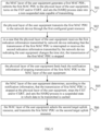
- FIG. 2 shows a flowchart of a data transmission method provided by an embodiment of the present disclosure, the method is applied to a user equipment, wherein the user equipment includes a MAC layer of the user equipment and a physical layer of the user equipment, and the method includes: step 201, submitting, by a media access control (MAC) layer of the user equipment, a first data packet to a physical layer of the user equipment, and starting a configured grant timer (CGT) and/or a configured grant retransmission timer (CGRT).
- MAC media access control
- the MAC layer of the user equipment first submits the first data packet to the physical layer of the user equipment, so that the physical layer of the user equipment transmits the received first data packet to a network device. After the MAC layer of the user equipment submits the first data packet to the physical layer of the user equipment, the CGT and/or the CGRT can be started.
- Step 202 stopping the CGT and/or the CGRT and transmitting the first data packet after stopping the CGT and/or the CGRT, in a case that the MAC layer of the user equipment identifies that transmission of the first data packet is stopped at the physical layer of the user equipment.
- the MAC layer of the user equipment may stop the CGT and/or the CGRT in a case that the transmission of the first data packet is stopped at the physical layer of the user equipment is identified. Specifically, in a case that CGT is started after transmitting the first data packet previously, CGT is stopped at this time, in a case that CGRT is started after transmitting the first data packet previously, CGRT is started at this time, in a case that CGRT and CGT are started after transmitting the first data packet previously, then CGRT and CGT are stopped at this time. After stopping the CGT and/or CGRT, the MAC layer of the user equipment may transmit the first data packet.
- the CGT and/or CGRT is stopped, and the first data packet is transmitted after stopping the CGT and/or CGRT, which can avoid performing data transmission actions after the timer expires, thereby ensuring that the user equipment completes the data transmission in advance, and saving time delay.
- the CGT and/or CGRT is stopped and the first data packet is transmitted after the CGT and/or CGRT stops, which can avoid performing data transmission actions after the timer expires, thereby ensuring that the user equipment completes data transmission in advance, and saving time delay.
- the method further includes:
- the physical layer of the user equipment can transmit the received first data packet to the network device, in a case that the target scenario is detected when transmitting the first data packet, the physical layer of the user equipment stops the transmission of first data packet, and feeds back the notification information of stopping transmission of the first data packet to the MAC layer of the user equipment.
- the MAC layer of the user equipment may know that the transmission of first data packet is stopped at the physical layer of the user equipment, and at this time, the MAC layer of the user equipment may stop the CGT and/or CGRT and transmit the first data packet after stopping the CGT and/or CGRT.
- the physical layer of the user equipment stops the transmission of the first data packet to the network device and notifies the MAC layer of the user equipment, so that the MAC layer of the user equipment can know the transmission status of the first data packet in time, and then collect corresponding measures to ensure the data transmission of the user equipment and save time delay.
- the physical layer of the user equipment stops the transmission of the first data packet, including one of the following methods of:
- the physical layer of the user equipment can stop, in a case that the second data packet meeting the preset condition is obtained when transmitting the first data packet, the transmission of the first data packet to the network device, wherein the second data packet may be another data packet submitted by the MAC layer of the user equipment to the physical layer of the user equipment, or may be a data packet generated by the physical layer of the user equipment itself. That is, in the process of transmitting the first data packet to the network device by the physical layer of the user equipment, in a case that the second data packet meeting the preset condition submitted by the MAC layer of the user equipment is received, the transmission of the first data packet to the network device may be stopped.
- the transmission of the first data packet to the network device may be stopped.
- the physical layer of the user equipment stops transmission of the first data packet to the network device; that is, during the process of transmitting the first data packet to the network device by the physical layer of the user equipment, in a case that the first indication information transmitted by the network device indicating that the transmission of the first data packet is interrupted is received, the transmission of the first data packet to the network device may be stopped according to the first indication information transmitted by the network device.
- the physical layer of the user equipment may stop transmission of the first data packet to the network device. That is, during the process of transmitting the first data packet to the network device by the physical layer of the user equipment, in a case that the second indication information transmitted by the network device indicating that the user equipment changes a time slot is received, the transmission of the first data packet to the network device may be stopped according to the second indication information transmitted by the network device.
- the transmission of the first data packet to the network device may be stopped based on the acquisition condition of the data packet or the instruction of the network device, so as to realize the control of stopping transmission of the first data packet according to the trigger of the user equipment or the network device.
- the stopping transmission of the first data packet includes:
- the data packets submitted by the MAC layer of the user equipment to the physical layer of the user equipment are all MAC PDUs, so the first data packet is the first MAC PDU, and in a case that the second data packet is a data packet submitted by the MAC layer of the user equipment to the physical layer of the user equipment, then the second data packet is a second MAC PDU, wherein the first data packet is transmitted to the network device through the first configured grant resource, the second data packet is transmitted to the network device through the first target uplink resource, the configured grant resource is selected from the uplink resource, and the configured grant resource may be used periodically to save PDCCH overhead.
- the specific process may be as follows: in a case that the physical layer of the user equipment receives the second MAC PDU submitted by the MAC layer of the user equipment when transmitting the first data packet, and the priority of the second MAC PDU is higher than the priority of the first data packet (the first MAC PDU), the transmission of the first data packet may be stopped.
- the specific process may also be as follows: in a case that the physical layer of the user equipment receives the second MAC PDU submitted by the MAC layer of the user equipment when transmitting the first data packet, and the priority of the first target uplink resource configured for transmitting the second MAC PDU is higher the priority of the first configured grant resource configured for transmitting the first data packet, then the transmission of the first data packet may be stopped.
- the specific process may also be as follows: in a case that the physical layer of the user equipment receives the second MAC PDU submitted by the MAC layer of the user equipment when transmitting the first data packet, and the priority of the first target uplink resource configured for transmitting the second MAC PDU is higher the priority of the first configured grant resource configured for transmitting the first data packet, and simultaneously, the priority of the second MAC PDU is higher than the priority of the first data packet, then the transmission of the first data packet may be stopped.
- the transmission of the first data packet to the network device can be stopped according to the second data packet meeting the preset condition, and the specific process may be as follows: in a case that the physical layer of the user equipment generates UCI when transmitting the first data packet, and the priority of the UCI generated by the physical layer of the user equipment is higher than the priority of the first data packet (the first MAC PDU), then the transmission of the first data packet may be stopped.
- UCI Uplink Control Information
- the specific process may also be as follows: in a case that the physical layer of the user equipment generates UCI when transmitting the first data packet, and the priority of the first target uplink resource configured for transmitting UCI is higher than the priority of the first configured grant resource configured for transmitting the first data packet, then the transmission of the first data packet may be stopped.
- the specific process may also be as follows: in a case that the physical layer of the user equipment generates UCI when transmitting the first data packet, and the priority of the first target uplink resource configured for transmitting the UCI generated by the physical layer of the user equipment is higher than the priority of the first configured grant resource configured for transmitting the first data packet, and simultaneously, the priority of the UCI generated by the physical layer of the user equipment is higher than the priority of the first data packet, then the transmission of the first data packet may be stopped.
- the stopping transmission of the first data packet may be triggered based on the priority of the second MAC PDU and/or the priority of the first target uplink resource configured for transmitting the second MAC PDU, or, the stopping transmission of the first data packet may be triggered based on the priority of the UCI and/or the priority of the first target uplink resource configured for transmitting the UCI, so as to trigger the stopping transmission of the first data packet according to the data and/or uplink resource with higher priority.
- the method further comprises: transmitting the second data packet by the physical layer of the user equipment.
- the physical layer of the user equipment may transmit the second data packet to the network device after stopping the transmission of the first data packet.
- the second data packet meeting the preset condition is that: the priority of the data packet is higher than the priority of the first data packet and/or the priority of the uplink resource configured for transmitting the data packet is higher than the priority of the uplink resource configured for transmitting the first data packet.
- the physical layer of the user equipment may transmit a data packet with a higher priority and/or transmit a data packet with a higher priority of uplink resource.
- the transmission of the first data packet includes:
- the user equipment can use the second target uplink resource to transmit the first data packet buffered in the MAC layer of the user equipment to the network device. Specifically, after the MAC layer of the user equipment determines the second target uplink resource, the physical layer of the user equipment transmits the first data packet buffered in the MAC layer of the user equipment to the network device through the second target uplink resource determined by the MAC layer of the user equipment.
- the first data packet is transmitted to the network device for a first time through the first configured grant resource; the selecting, by the MAC layer of the user equipment, the second target uplink resource from at least one uplink resource, includes: selecting, by the MAC layer of the user equipment, the second target uplink resource from at least one uplink resource according to at least one of a modulation and coding scheme (MCS) of the uplink resource and a reliability parameter of the uplink resource.
- MCS modulation and coding scheme
- the MAC layer of the user equipment selects the second target uplink resource from at least one uplink resource
- the second target uplink resource may be selected from at least one uplink resource according to the MCS of the uplink resource, or the second target uplink resource may be selected from at least one uplink resource according to the reliability parameter of the uplink resource, or the second target uplink resource may be selected from at least one uplink resource according to the MCS of the uplink resource and the reliability parameter of the uplink resource.
- the second target uplink resource may be selected based on at least one of the MCS of the uplink resource and the reliability parameter of the uplink resource, which enriches the selection manners of the second target uplink resource.
- the selecting, by the MAC layer of the user equipment, the second target uplink resource from at least one uplink resource according to at least one of the modulation and coding scheme (MCS) of the uplink resource and the reliability parameter of the uplink resource includes one of:
- the second target uplink resource is selected according to at least one of the MCS of the uplink resource and the reliability parameter of the uplink resource.
- the MAC layer of the user equipment selects an uplink resource whose MCS is lower than or equal to the MCS corresponding to the first configured grant resource from at least one uplink resource, and uses the selected uplink resource as the second target uplink resource, in a case that at least two uplink resources meeting the requirements may be selected according to the MCS, the uplink resource selected for the first time may be determined as the second target uplink resource, or the second target uplink resource may be determined from at least two uplink resources meeting the requirements based on a preset policy.
- the MAC layer of the user equipment selects an uplink resource whose reliability parameter is higher than or equal to the reliability parameter corresponding to the first configured grant resource from at least one uplink resource, and uses the selected uplink resource as the second target uplink resource, in a case that at least two uplink resources meeting the requirements may be selected according to the reliability parameters, the uplink resource selected for the first time may be determined as the second target uplink resource, or the second target uplink resource may be determined from at least two uplink resources meeting requirements based on a preset policy.
- the MAC layer of the user equipment selects an uplink resource whose MCS is lower than or equal to the MCS corresponding to the first configured grant resource and whose reliability parameter is higher than or equal to the reliability parameter corresponding to the first configured grant resource from at least one uplink resource, and uses the selected uplink resource as the second target uplink resource, in a case that at least two uplink resources meeting the requirements can be selected according to the MCS and the reliability parameters, the uplink resource selected for the first time can be determined as the second target uplink resource, or the second target uplink resource may be determined from at least two uplink resources meeting requirements based on a preset policy.
- the reliability parameter may be a parameter configured by the network device for uplink resource.
- the second target uplink resource is selected from the uplink resources based on at least one of the MCS and the reliability parameter, which can realize a selection for a resource with high reliability on the basis of enriching the selection manners of the second target uplink resource.
- the method further includes:
- the MAC layer of the user equipment After starting the CGT and/or CGRT, the MAC layer of the user equipment needs to set the HARQ process to a non-suspended state capable of transmitting, and data buffered in HARQ has been transmitted may be represented by setting the state of the HARQ process.
- the MAC layer of the user equipment After stopping CGT and/or CGRT, the MAC layer of the user equipment needs to set the HARQ process to the suspended state in which data to be transmitted is buffered, and data to be transmitted is buffered in HARQ may be represented by setting the state of the HARQ process, after setting the HARQ process to a suspended state in which data to be transmitted is buffered, the buffered first data packet may be transmitted.
- the data transmission method provided by the embodiments of the present disclosure will be described below through two specific processes.
- the specific process of the data transmission method is shown in FIG. 3 .
- Step 301 the MAC layer of the user equipment generates a first MAC PDU, submits the first MAC PDU to the physical layer of the user equipment, and turns on the CGT and/or CGRT, and sets the HARQ process state to a non-suspended state capable of transmitting.
- Step 302 the physical layer of the user equipment transmits the first MAC PDU to the network device through the first configured grant resource.
- Step 303 in a case that the second data packet submitted by the MAC layer of the user equipment is received or the second data packet is generated at the physical layer of the user equipment, the physical layer of the user equipment stops the transmission of the first MAC PDU, and executes the transmission of the second data packet, wherein the priority of the second data packet is higher than the priority of the first MAC PDU and/or the priority of the first target uplink resource configured for transmitting the second data packet is higher than the priority of the first configured grant resource configured for transmitting the first MAC PDU, and the second data packet is the second MAC PDU or UCI.
- Step 304 the physical layer of the user equipment feeds back the notification information of stopping transmission of the first MAC PDU to the MAC layer of the user equipment.
- Step 305 the MAC layer of the user equipment determines that the transmission of first MAC PDU is stopped at the physical layer of the user equipment according to the notification information, stops the CGT and/or CGRT, and sets the HARQ process to a suspended state in which data to be transmitted is buffered.
- Step 306 the MAC layer of the user equipment selects the second target uplink resource, and transmits the first MAC PDU on the second target uplink resource.
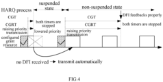
- the transmission mechanism corresponding to the above-mentioned implementation process can be referred in FIG. 4 , the data packet is submitted from the MAC layer to the physical layer, and CGT and CGRT are turned on, but transmission interruption occurs at the physical layer (the physical layer transmits other data preferentially or interrupts, according to the instructions of the network device, the current data transmission), the MAC layer turns off CGT and CGRT, transmits data packet, so as to reduce the time delay of data transmission.
- the specific process of the data transmission method is shown in FIG. 5 .
- Step 501 the MAC layer of the user equipment generates a first MAC PDU, submits the first MAC PDU to the physical layer of the user equipment, and turns on the CGT and/or CGRT, and sets the HARQ process state to a non-suspended state capable of transmitting.
- Step 502 the physical layer of the user equipment transmits the first MAC PDU to the network device through the first configured grant resource.
- Step 503 in a case that the physical layer of the user equipment receives the first indication information transmitted by network device indicating that the transmission of the first MAC PDU is interrupted or receives the second indication information transmitted by the network device indicating the user equipment changes the time slot, the transmission of the first MAC PDU is stopped.
- Step 504 the physical layer of the user equipment feeds back the notification information of stopping transmission of the first MAC PDU to the MAC layer of the user equipment.
- Step 505 the MAC layer of the user equipment determines that the transmission of first MAC PDU is stopped at the physical layer of the user equipment according to the notification information, stops the CGT and/or CGRT, and sets the HARQ process to a suspended state in which data to be transmitted is buffered.
- Step 506 the MAC layer of the user equipment selects the second target uplink resource, and transmits the first MAC PDU on the second target uplink resource.
- the transmission mechanism corresponding to the implementation process may also be shown in FIG. 4 .
- the above is the overall implementation process of the data transmission method provided by the embodiment of the present disclosure.
- the MAC layer of the user equipment submits the first data packet to the physical layer of the user equipment and starts the CGT and/or CGRT
- stopping the CGT and/or the CGRT to stop and transmit the first data packet can avoid performing the data transmission action after the timer expires and ensure that the user equipment completes the data transmission in advance to save time delay.
- the present disclosure can realize the control of stopping transmission of the first data packet according to the trigger of the user equipment or the network equipment, and can also realize the selection of highly reliable resources on the basis of enriching the selection manners of the second target uplink resource.
- an embodiment of the present disclosure also provides a data transmission apparatus, applied to user equipment, including: a MAC layer processing module 61 of the user equipment and a physical layer processing module 62 of the user equipment; the MAC layer processing module 61 of the user equipment includes:
- the physical layer processing module of the user equipment is further configured to:
- the physical layer processing module of the user equipment includes one of the following submodules:
- the first stop submodule is further configured for:
- the physical layer processing module of the user equipment further includes: a transmitting submodule, configured to transmit the second data packet after the first stop submodule stops the transmission of the first data packet.
- the second processing submodule includes:
- the first data packet is transmitted to the network device for the first time through the first configured grant resource; the selection unit is further configured to: select the second target uplink resource from at least one uplink resource according to at least one of a modulation and coding scheme (MCS) of the uplink resource and a reliability parameter of the uplink resource.
- MCS modulation and coding scheme
- the selection unit includes one of the following subunits:
- the MAC layer processing module of the user equipment further includes:
- each functional unit in each embodiment of the present disclosure may be integrated into one processing unit, each unit may exist separately physically, or two or more units may be integrated into one unit.
- the above-mentioned integrated units can be implemented in the form of hardware or in the form of software functional units.
- the integrated unit is implemented in the form of a software function unit and sold or used as an independent product, it can be stored in a processor-readable storage medium.
- the technical solution of the present disclosure is essentially or part of the contribution to the prior art, or all or part of the technical solution can be embodied in the form of a software product, and the computer software product is stored in a storage medium, including several instructions used for enabling a computer device (which may be a personal computer, server, or network device, etc.) or a processor (processor) to execute all or part of the steps of the methods described in various embodiments of the present disclosure.
- the aforementioned storage media includes: U disk, mobile hard disk, read-only memory (Read-Only Memory, ROM), random access memory (Random Access Memory, RAM), magnetic disk or optical disk and other media that can store program codes.
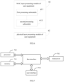
- An embodiment of the present disclosure also provides a user equipment, as shown in FIG. 7 , the user equipment includes a memory 701, a transceiver 702, and a processor 703, wherein the memory 701 is configured for storing computer program; the transceiver 702 is configured for receiving and sending data under the control of the processor 703; and the processor 703 is configured for reading the computer program in the memory 701 and performing the following operations of:
- the processor 703 is further configured for: controlling the physical layer of the user equipment to stop, in a case that a target scenario is detected when transmitting the first data packet, transmission of the first data packet, and feed back notification information to the MAC layer of the user equipment, wherein the MAC layer of the user equipment identifies that transmission of the first data packet is stopped according to the notification information.
- the processor 703 controls the physical layer of the user equipment to stop the transmission of the first data packet
- the processor is specifically configured to perform one of the following methods of:
- the processor 703 controls the physical layer of the user equipment to stop, in a case that the second data packet meeting the preset condition is obtained when transmitting the first data packet, transmission of the first data packet, the processor is specially configured for:
- the processor 703 controls the physical layer of the user equipment to stop, in a case that the second data packet meeting the preset condition is obtained when transmitting the first data packet, transmission of the first data packet, the processor is further configured for: controlling the physical layer of the user equipment to transmit the second data packet.
- the processor 703 controls the MAC layer of the user equipment to transmit the first data packet
- the processor is specifically configured for: controlling the MAC layer of the user equipment to select a second target uplink resource from at least one uplink resource; and controlling the physical layer of the user equipment to transmit the buffered first data packet to the network device through the second target uplink resource.
- the first data packet is transmitted to the network device for a first time through the first configured grant resource; when the processor 703 controls the MAC layer of the user equipment to select the second target uplink resource from at least one uplink resource, the processor is specially configured for: controlling the MAC layer of the user equipment to select, according to at least one of a modulation and coding scheme (MCS) of the uplink resource and a reliability parameter of the uplink resource, the second target uplink resource from at least one uplink resource.
- MCS modulation and coding scheme
- the processor 703 controls the MAC layer of the user equipment to select, according to at least one of the modulation and coding scheme (MCS) of the uplink resource and the reliability parameter of the uplink resource, the second target uplink resource from at least one uplink resource, the processor is specially configured for performing one of the following methods of:
- MCS modulation and coding scheme
- the processor 703 controls the MAC layer of the user equipment to start the CGT and/or the CGRT, the processor is further configured for:
- the bus architecture may include any number of interconnected buses and bridges, specifically one or more processors represented by the processor 703 and various circuits of the memory represented by the memory 701 are linked together.
- the bus architecture can also link together various other circuits such as peripherals, voltage regulators, and power management circuits, etc., which are well known in the art and therefore will not be further described herein.
- the bus interface provides the interface.
- the transceiver 702 may be a plurality of elements, including a transmitter and a receiver, which provides a unit for communicating with various other devices over transmission media, these transmission media includes wireless channels, wired channels, optical cables, and other transmission media.
- the user interface 704 may also be an interface capable of connecting externally and internally to required equipment, and the connected equipment includes but not limited to a keypad, a display, a speaker, a microphone, a joystick, and the like.
- the processor 703 is responsible for managing the bus architecture and general processing, and the memory 701 can store data used by the processor 703 when performing operations.
- the processor 703 may be a central processor (CPU), an application specific integrated circuit (Application Specific Integrated Circuit, ASIC), a field programmable gate array (Field-Programmable Gate Array, FPGA) or a complex programmable logic device (Complex Programmable Logic Device, CPLD), and the processor can also use a multi-core architecture.
- CPU central processor
- ASIC Application Specific Integrated Circuit
- FPGA field programmable gate array
- CPLD Complex Programmable Logic Device
- the processor is configured for executing any one of the methods provided by the embodiments of the present disclosure according to the obtained executable instructions by calling the computer program stored in the memory.
- the processor and memory may also be physically separated.
- An embodiment of the present disclosure also provides a processor-readable storage medium, wherein a computer program is stored in the processor-readable storage medium, and the computer program is configured for enabling the processor to execute the data transmission method.
- the processor-readable storage medium can be any available medium or data storage device that can be accessed by a processor, including but not limited to magnetic storage (such as floppy disk, hard disk, magnetic tape, magneto-optical disk (MO), etc.), optical storage (such as CD, DVD, BD, HVD, etc.), and semiconductor memory (such as ROM, EPROM, EEPROM, non-volatile memory (NAND FLASH), solid-state drive (SSD)), etc.
- magnetic storage such as floppy disk, hard disk, magnetic tape, magneto-optical disk (MO), etc.
- optical storage such as CD, DVD, BD, HVD, etc.
- semiconductor memory such as ROM, EPROM, EEPROM, non-volatile memory (NAND FLASH), solid-state drive (SSD)
- An embodiment of the present disclosure also provides a computer program, including computer readable codes, which enables, when the computer readable codes are run on a computing processing device, the computing processing device to execute the above-mentioned data transmission method.
- the embodiments of the present disclosure may be provided as methods, systems, or computer program products. Accordingly, the present disclosure can take the form of an entirely hardware embodiment, an entirely software embodiment, or an embodiment combining software and hardware aspects. Furthermore, the present disclosure may take the form of a computer program product embodied on one or more computer-usable storage media (including but not limited to magnetic disk storage, optical storage, etc.) having computer-usable program code embodied therein.
- a computer-usable storage media including but not limited to magnetic disk storage, optical storage, etc.
- processor-executable instructions may also be stored in a processor-readable memory capable of directing a computer or other programmable data processing device to operate in a specific manner, such that the instructions stored in the processor-readable memory produce a manufacturing product including instruction device, the instruction device realizes the function specified in one or more procedures of the flow chart and/or one or more blocks of the block diagram.
- processor-executable instructions can also be loaded onto a computer or other programmable data processing device, which enables a series of operational steps to be performed on the computer or other programmable device to produce a computer-implemented process, whereby the instructions executed on the computer or other programmable device provide the steps for implementing the function specified in one or more procedures of the flow chart and/or one or more blocks of the block diagram.
- the device embodiments described above are only illustrative, and the units described as separate components may or may not be physically separated, and the components shown as units may or may not be physical units, that is, they may be located in one place, or can be distributed to multiple network elements. Part or all of the modules can be selected according to actual needs to achieve the purpose of the solution of this embodiment. It can be understood and implemented by those skilled in the art without any creative efforts.
- the various component embodiments of the present disclosure may be implemented in hardware, or in software modules running on one or more processors, or in a combination thereof.
- a microprocessor or a digital signal processor (DSP) may be used in practice to implement some or all functions of some or all components in the computing processing device according to the embodiments of the present disclosure.
- DSP digital signal processor
- the present disclosure can also be implemented as a device or apparatus program (eg, computer program and computer program product) for performing a part or all of the methods described herein.
- Such a program realizing the present disclosure may be stored on a computer-readable medium, or may have the form of one or more signals.
- Such a signal may be downloaded from an Internet site, or provided on a carrier signal, or provided in any other form.
- FIG. 8 illustrates a computing processing device that may implement methods according to the present disclosure.
- the computing processing device conventionally includes a processor 810 and a computer program product or computer readable medium in the form of memory 820.
- Memory 820 may be electronic memory such as flash memory, EEPROM (Electrically Erasable Programmable Read Only Memory), EPROM, hard disk, or ROM.
- the memory 820 has storage space 830 for program code 831 for performing any of the method steps in the methods described above.
- the storage space 830 for program codes may include respective program codes 831 for respectively implementing various steps in the above-mentioned methods. These program codes can be read from or written into one or more computer program products.
- Such computer program products include program code carriers such as hard disks, compact disks (CDs), memory cards or floppy disks.
- Such a computer program product is typically a portable or fixed storage unit as described with reference to FIG. 9 .
- the storage unit may have storage segments, storage spaces, etc. arranged similarly to the memory 820 in the computing processing device of FIG. 8 , for example, the program code may be compressed in a suitable form.
- the storage unit includes computer readable code 831', i.e. code readable by, for example, a processor such as 810, which code enables, when executed by a computing processing device, the computing processing device to perform the steps in the methods described above.
- any reference signs placed between parentheses shall not be construed as limiting the claim.
- the word “comprising” does not exclude the presence of elements or steps not listed in a claim.
- the word “a” or “an” preceding an element does not exclude the presence of a plurality of such elements.
- the disclosure can be implemented by means of hardware comprising several different elements, and by means of a suitably programmed computer. In a unit claim enumerating several apparatuses, several of these apparatuses can be embodied by the same item of hardware.
- the use of the words first, second, and third, etc. does not indicate any order. These words can be interpreted as names.
Landscapes
- Engineering & Computer Science (AREA)
- Computer Networks & Wireless Communication (AREA)
- Signal Processing (AREA)
- Quality & Reliability (AREA)
- Mobile Radio Communication Systems (AREA)
Applications Claiming Priority (2)
| Application Number | Priority Date | Filing Date | Title |
|---|---|---|---|
| CN202011149169.5A CN114501531B (zh) | 2020-10-23 | 2020-10-23 | 一种数据传输方法、装置及设备 |
| PCT/CN2021/123427 WO2022083480A1 (zh) | 2020-10-23 | 2021-10-13 | 一种数据传输方法、装置及设备 |
Publications (2)
| Publication Number | Publication Date |
|---|---|
| EP4236441A1 true EP4236441A1 (de) | 2023-08-30 |
| EP4236441A4 EP4236441A4 (de) | 2024-03-13 |
Family
ID=81291611
Family Applications (1)
| Application Number | Title | Priority Date | Filing Date |
|---|---|---|---|
| EP21881898.7A Pending EP4236441A4 (de) | 2020-10-23 | 2021-10-13 | Datenübertragungsverfahren und -vorrichtung sowie vorrichtung |
Country Status (6)
| Country | Link |
|---|---|
| US (1) | US20230397189A1 (de) |
| EP (1) | EP4236441A4 (de) |
| JP (1) | JP7580597B2 (de) |
| KR (1) | KR20230088907A (de) |
| CN (1) | CN114501531B (de) |
| WO (1) | WO2022083480A1 (de) |
Families Citing this family (4)
| Publication number | Priority date | Publication date | Assignee | Title |
|---|---|---|---|---|
| US11736972B2 (en) * | 2021-03-31 | 2023-08-22 | Qualcomm Incorporated | Protocol overhead reduction |
| WO2023003206A1 (en) * | 2021-07-22 | 2023-01-26 | Lg Electronics Inc. | Method and apparatus for transmitting uplink control information multiplexed data by ue in wireless communication system |
| US12604335B2 (en) * | 2021-10-20 | 2026-04-14 | Samsung Electronics Co., Ltd. | Method and apparatus for transmission data selection considering simultaneous cell transmission |
| CN119698783A (zh) * | 2022-08-09 | 2025-03-25 | Lg电子株式会社 | 无线通信系统中在装置内共存问题期间执行自主重传的方法和设备 |
Family Cites Families (18)
| Publication number | Priority date | Publication date | Assignee | Title |
|---|---|---|---|---|
| CN101431398B (zh) * | 2007-11-05 | 2012-04-25 | 华为技术有限公司 | 控制保护设备保持激活状态的方法及设备 |
| US10484129B2 (en) * | 2016-01-21 | 2019-11-19 | Qualcomm Incorporated | Protocol layer packet coding for transmitter/receiver buffer optimization |
| WO2018027656A1 (zh) * | 2016-08-10 | 2018-02-15 | 华为技术有限公司 | 混合自动重传请求的方法和终端设备 |
| CN110035502B (zh) * | 2018-01-11 | 2021-06-08 | 华为技术有限公司 | 通信方法、通信设备和网络设备 |
| KR102627291B1 (ko) * | 2018-08-07 | 2024-01-23 | 텔레호낙티에볼라게트 엘엠 에릭슨(피유비엘) | Harq 송신을 용이하게 하기 위한 방법 및 디바이스 |
| WO2020091578A1 (ko) * | 2018-11-02 | 2020-05-07 | 엘지전자 주식회사 | 무선 통신 시스템에서 데이터를 송수신하기 위한 방법 및 이를 위한 장치 |
| JP7124261B2 (ja) * | 2018-11-09 | 2022-08-24 | ハンニバル アイピー エルエルシー | 上りリンク送信のための方法及び装置 |
| CN111181693B (zh) * | 2018-11-09 | 2021-08-31 | 华为技术有限公司 | 发送数据的方法、发送数据的装置、以及终端设备 |
| WO2020107489A1 (zh) * | 2018-11-30 | 2020-06-04 | Oppo广东移动通信有限公司 | 一种无线通信方法和通信设备 |
| US12052729B2 (en) * | 2019-03-28 | 2024-07-30 | JRD Communication (Shenzhen) Ltd. | Transmission pre-emption |
| KR102814700B1 (ko) * | 2019-04-30 | 2025-05-29 | 삼성전자주식회사 | 무선 통신 시스템에서 데이터를 송수신하는 방법 및 장치 |
| CN110167188B (zh) * | 2019-05-27 | 2022-07-26 | 南京邮电大学 | 一种未授权频段中的sr自适应配置方法 |
| CN114208079B (zh) * | 2019-08-15 | 2024-05-07 | 富士通株式会社 | 数据传输的方法及其装置、通信系统 |
| EP4094389B1 (de) * | 2020-01-24 | 2025-03-12 | Telefonaktiebolaget LM Ericsson (publ) | Handhabung eines hybriden automatischen wiederholungsaufforderungsverfahrens bei der aktivierung und deaktivierung von konfigurationsberechtigungen |
| US12381660B2 (en) * | 2020-01-31 | 2025-08-05 | Telefonaktiebolaget Lm Ericsson (Publ) | Transport block repetition with multiple uplink configured grant configurations |
| WO2021160352A1 (en) * | 2020-02-13 | 2021-08-19 | Telefonaktiebolaget Lm Ericsson (Publ) | Conditionally handling hybrid automatic repeat request process in configuration grant activation procedure |
| WO2021194271A1 (en) * | 2020-03-26 | 2021-09-30 | Lg Electronics Inc. | Harq transmission using timers for configured grants and discontinuous reception |
| WO2022061249A1 (en) * | 2020-09-20 | 2022-03-24 | Babaei Alireza | Enhanced wireless device and wireless network processes |
-
2020
- 2020-10-23 CN CN202011149169.5A patent/CN114501531B/zh active Active
-
2021
- 2021-10-13 US US18/033,353 patent/US20230397189A1/en active Pending
- 2021-10-13 EP EP21881898.7A patent/EP4236441A4/de active Pending
- 2021-10-13 KR KR1020237016916A patent/KR20230088907A/ko active Pending
- 2021-10-13 WO PCT/CN2021/123427 patent/WO2022083480A1/zh not_active Ceased
- 2021-10-13 JP JP2023524960A patent/JP7580597B2/ja active Active
Also Published As
| Publication number | Publication date |
|---|---|
| KR20230088907A (ko) | 2023-06-20 |
| JP2023546251A (ja) | 2023-11-01 |
| CN114501531A (zh) | 2022-05-13 |
| CN114501531B (zh) | 2025-03-18 |
| WO2022083480A1 (zh) | 2022-04-28 |
| JP7580597B2 (ja) | 2024-11-11 |
| US20230397189A1 (en) | 2023-12-07 |
| EP4236441A4 (de) | 2024-03-13 |
Similar Documents
| Publication | Publication Date | Title |
|---|---|---|
| US20220182899A1 (en) | Pucch transmission method, user equipment, and network device | |
| US10966281B2 (en) | Transmission timing information sending method, transmission timing information receiving method, and apparatus | |
| EP4236441A1 (de) | Datenübertragungsverfahren und -vorrichtung sowie vorrichtung | |
| JP7703828B2 (ja) | 上りリンク信号の送受信方法及び装置 | |
| CN112272963B (zh) | 蜂窝无线通信网络中的上行链路复用 | |
| WO2022117102A1 (zh) | 上行控制信息传输方法、接收方法、终端和网络设备 | |
| WO2021026844A1 (zh) | 数据传输方法、终端设备、网络设备及存储介质 | |
| CN116827504A (zh) | Harq码本发送方法、接收方法、装置及存储介质 | |
| TW202329737A (zh) | 上行鏈路控制資訊傳輸方法、終端、網路設備、裝置及存儲介質 | |
| EP4319014A1 (de) | Verfahren und vorrichtung zur verzögerungsreduzierung, endgerät und vorrichtung | |
| CN115334659B (zh) | 一种信息确认方法、装置及通信设备 | |
| CN111988117B (zh) | 一种时隙聚合处理方法及通信设备 | |
| CN115941124B (zh) | Harq-ack反馈方法和装置 | |
| CN115706636A (zh) | 一种数据包激活方法、装置、网络设备和终端 | |
| CN115190599A (zh) | 一种上行信道的传输方法及装置 | |
| CN114390682A (zh) | 一种上行传输方法及装置 | |
| CN115883025B (zh) | 动态数据传输方法、装置及存储介质 | |
| CN115174008B (zh) | 数据传输方法、装置及存储介质 | |
| EP4485829A1 (de) | Informationsverarbeitungsverfahren und -vorrichtung und lesbares speichermedium | |
| CN115175324B (zh) | 一种信道复用方法、装置及通信设备 | |
| EP4561223A1 (de) | Informationsverarbeitungsverfahren und -vorrichtung sowie lesbares speichermedium | |
| EP4507229A1 (de) | Informationsverarbeitungsverfahren und -vorrichtung sowie lesbares speichermedium | |
| CN116489791A (zh) | 上行传输方法、终端设备和网络设备 | |
| TW202508355A (zh) | Sl prs資源確定方法、指示方法、裝置及存儲介質 | |
| WO2026017252A1 (en) | Handling resource assignment for feedback reception in wireless communication network |
Legal Events
| Date | Code | Title | Description |
|---|---|---|---|
| STAA | Information on the status of an ep patent application or granted ep patent |
Free format text: STATUS: THE INTERNATIONAL PUBLICATION HAS BEEN MADE |
|
| PUAI | Public reference made under article 153(3) epc to a published international application that has entered the european phase |
Free format text: ORIGINAL CODE: 0009012 |
|
| STAA | Information on the status of an ep patent application or granted ep patent |
Free format text: STATUS: REQUEST FOR EXAMINATION WAS MADE |
|
| 17P | Request for examination filed |
Effective date: 20230508 |
|
| AK | Designated contracting states |
Kind code of ref document: A1 Designated state(s): AL AT BE BG CH CY CZ DE DK EE ES FI FR GB GR HR HU IE IS IT LI LT LU LV MC MK MT NL NO PL PT RO RS SE SI SK SM TR |
|
| DAV | Request for validation of the european patent (deleted) | ||
| DAX | Request for extension of the european patent (deleted) | ||
| A4 | Supplementary search report drawn up and despatched |
Effective date: 20240212 |
|
| RIC1 | Information provided on ipc code assigned before grant |
Ipc: H04W 72/1268 20230101ALN20240206BHEP Ipc: H04W 72/115 20230101ALN20240206BHEP Ipc: H04L 1/1822 20230101ALI20240206BHEP Ipc: H04L 5/00 20060101ALI20240206BHEP Ipc: H04L 1/1867 20230101ALI20240206BHEP Ipc: H04L 1/00 20060101ALI20240206BHEP Ipc: H04W 28/02 20090101AFI20240206BHEP |