EP4237196B1 - Dispositif pour couper ou scier au couteau des pièces à usiner - Google Patents
Dispositif pour couper ou scier au couteau des pièces à usiner Download PDFInfo
- Publication number
- EP4237196B1 EP4237196B1 EP22723091.9A EP22723091A EP4237196B1 EP 4237196 B1 EP4237196 B1 EP 4237196B1 EP 22723091 A EP22723091 A EP 22723091A EP 4237196 B1 EP4237196 B1 EP 4237196B1
- Authority
- EP
- European Patent Office
- Prior art keywords
- support surface
- layer
- openings
- chamber
- cross
- Prior art date
- Legal status (The legal status is an assumption and is not a legal conclusion. Google has not performed a legal analysis and makes no representation as to the accuracy of the status listed.)
- Active
Links
Images

Classifications
-
- B—PERFORMING OPERATIONS; TRANSPORTING
- B25—HAND TOOLS; PORTABLE POWER-DRIVEN TOOLS; MANIPULATORS
- B25B—TOOLS OR BENCH DEVICES NOT OTHERWISE PROVIDED FOR, FOR FASTENING, CONNECTING, DISENGAGING, OR HOLDING
- B25B11/00—Work holders not covered by any preceding group in the subclass, e.g. magnetic work holders, vacuum work holders
- B25B11/005—Vacuum work holders
-
- B—PERFORMING OPERATIONS; TRANSPORTING
- B26—HAND CUTTING TOOLS; CUTTING; SEVERING
- B26D—CUTTING; DETAILS COMMON TO MACHINES FOR PERFORATING, PUNCHING, CUTTING-OUT, STAMPING-OUT OR SEVERING
- B26D7/00—Details of apparatus for cutting, cutting-out, stamping-out, punching, perforating, or severing by means other than cutting
- B26D7/01—Means for holding or positioning work
- B26D7/018—Holding the work by suction
-
- B—PERFORMING OPERATIONS; TRANSPORTING
- B26—HAND CUTTING TOOLS; CUTTING; SEVERING
- B26D—CUTTING; DETAILS COMMON TO MACHINES FOR PERFORATING, PUNCHING, CUTTING-OUT, STAMPING-OUT OR SEVERING
- B26D7/00—Details of apparatus for cutting, cutting-out, stamping-out, punching, perforating, or severing by means other than cutting
- B26D7/06—Arrangements for feeding or delivering work of other than sheet, web, or filamentary form
- B26D7/0616—Arrangements for feeding or delivering work of other than sheet, web, or filamentary form by carriages, e.g. for slicing machines
-
- B—PERFORMING OPERATIONS; TRANSPORTING
- B26—HAND CUTTING TOOLS; CUTTING; SEVERING
- B26D—CUTTING; DETAILS COMMON TO MACHINES FOR PERFORATING, PUNCHING, CUTTING-OUT, STAMPING-OUT OR SEVERING
- B26D7/00—Details of apparatus for cutting, cutting-out, stamping-out, punching, perforating, or severing by means other than cutting
- B26D7/06—Arrangements for feeding or delivering work of other than sheet, web, or filamentary form
- B26D7/0625—Arrangements for feeding or delivering work of other than sheet, web, or filamentary form by endless conveyors, e.g. belts
-
- B—PERFORMING OPERATIONS; TRANSPORTING
- B23—MACHINE TOOLS; METAL-WORKING NOT OTHERWISE PROVIDED FOR
- B23Q—DETAILS, COMPONENTS, OR ACCESSORIES FOR MACHINE TOOLS, e.g. ARRANGEMENTS FOR COPYING OR CONTROLLING; MACHINE TOOLS IN GENERAL CHARACTERISED BY THE CONSTRUCTION OF PARTICULAR DETAILS OR COMPONENTS; COMBINATIONS OR ASSOCIATIONS OF METAL-WORKING MACHINES, NOT DIRECTED TO A PARTICULAR RESULT
- B23Q3/00—Devices holding, supporting, or positioning work or tools, of a kind normally removable from the machine
- B23Q3/02—Devices holding, supporting, or positioning work or tools, of a kind normally removable from the machine for mounting on a work-table, tool-slide, or analogous part
- B23Q3/06—Work-clamping means
- B23Q3/08—Work-clamping means other than mechanically-actuated
- B23Q3/088—Work-clamping means other than mechanically-actuated using vacuum means
Definitions
- the invention relates to a device for knife cutting or sawing workpieces according to the preamble of patent claim 1.
- Knife cutting and sawing are machining methods for workpieces defined in accordance with DIN standards (e.g. DIN 8588 and DIN 8589-6). Knife cutting refers to the cutting of a workpiece using at least one knife, and sawing refers to the machining of a workpiece. Smooth and toothed knives are used in particular for knife cutting, and saw blades with interlocking teeth are used for sawing. In contrast to machining, intermediate products or end products are cut out of a semi-finished product, which form the good part. With machining, the material removed is never the good part. Here, the workpiece is to be removed successively in order to produce a plurality of good parts.
- DIN standards e.g. DIN 8588 and DIN 8589-6.
- the base In order to suck the workpiece from its underside, the base has a large number of through-openings which are fluidically connected to a unit for generating a negative pressure.
- the base In order to process the widest possible range of applications and a large number of workpieces, it is usual for the base to be larger than the workpiece to be processed. In the area where the workpiece rests, the through holes are closed by the workpiece, but there may be through holes on the side of the workpiece that are open to the environment.
- the underlying aim of the invention is to provide a device for knife cutting or sawing workpieces, by means of which a particularly high holding force can be exerted on the workpiece to be processed as easily as possible and at the same time the noise pollution is reduced.
- a device according to the invention is used for knife cutting or sawing workpieces and has a cutting unit or a sawing unit.
- knife cutting and sawing as well as the workpieces and materials intended for processing here, reference is made to the above description.
- the device is composed according to claim 1.
- At least one chamber is formed beneath the support surface and the chamber is fluidically connected to a unit for generating a negative pressure in such a way that in an operating state a volume flow is conveyed along a flow direction through the through openings and the at least one chamber.
- a unit for generating a negative pressure Any type of vacuum pump, axial fan, radial fan or even passive elements such as a Venturi nozzle can be used. This negative pressure also acts on the workpiece via the through holes closed by the workpiece and the workpiece is held on the support surface.
- the first area is formed by the support surface and the second area by a layer of porous material arranged downstream of the support surface.
- the through openings or pores in the porous material have a smaller cross-sectional area than the through openings in the support surface.
- the ratio of the cross-sectional area of the pores to the inlet length is also advantageous.
- Cork, fleece, a rubber composite or a rubber-cork composite are particularly suitable as porous materials. With a layer of porous material, many through openings with a small cross-sectional area can be created in a simple manner. In particular, the layer of porous material can be obtained inexpensively as a mat.
- a layer of porous material has the additional effect of acting as a silencer itself, which further reduces the noise level when the device is in operation.
- the layer of porous material had a thickness of 0.5 mm to 10 mm and preferably of 1 mm to 5 mm.
- the other advantageous properties of the individual areas are also exploited, namely the inexpensive and sound-absorbing layer of porous material and the elasticity of the layer of air-impermeable material.
- the layer of porous material can also be supported by a support structure as described above.
- an endless conveyor belt is arranged upstream of the support surface, which is designed to run around a table with an integrated chamber.
- the conveyor belt can be a layer of an air-impermeable material as described above, which is additionally designed to run around the table.
- the conveyor belt can have through-openings, in particular with the same or smaller cross-sectional areas as the support surface.
- the support surface has several elongated holes extending in the direction of movement in order to to ensure that the negative pressure is transferred as evenly as possible to the workpiece via the through holes in the conveyor belt.
- the layer of porous material is then arranged particularly downstream of the stationary support surface.
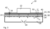
- FIG. 1 and 2 a first embodiment of a device 10 for knife cutting or sawing workpieces 12 is shown.
- a cutting unit or sawing unit is not shown here for the sake of clarity.
- the device 10 has a support surface 14 with through holes 16.
- the through holes 16 have a cross-sectional area A1.
- the unit for generating a negative pressure 22 In order to hold the workpiece 12 on the support surface 14, the unit for generating a negative pressure 22 is used.
- the unit for generating a negative pressure 22 conveys a volume flow according to the arrows in the flow direction through the through openings 16 in the support surface 14, through the through openings or pores 32 of the layer 30 made of the porous material into the chamber 18. From there, the volume flow is conveyed through the connection 20 and a line 36 to the unit for generating a negative pressure 22.
- the layer 30 made of porous material creates a cross-sectional constriction, so that a small volume flow is conveyed through the open through holes 16 at the side of the workpiece 12 and therefore a significantly higher negative pressure is generated in the chamber 18 by the unit to generate the negative pressure 22.
- This increased negative pressure is applied to the workpiece 12 via the through openings 16 closed by the workpiece 12, which is thus held particularly well on the support surface 14.
- the device 10 according to this first embodiment with the reversing table has only a single unit for generating a negative pressure 22.
- the unit for generating a negative pressure 22 is arranged at a distance from the reversing table with the support surface 14 and the chamber 18 and is stationary.
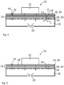
- a second embodiment of a device 10 is shown. This is also a reversing table.
- This second embodiment differs from the first embodiment in that a layer 40 of air-impermeable material is arranged upstream of the support surface 14.
- This layer 40 of air-impermeable material has through-openings 42 with an opening cross-section A3.
- the opening cross-section A3 of the through-openings 42 corresponds to the opening cross-section A1 of the through-openings 16 in the support surface.
- cross-sectional area A3 of the through-openings 42 of the layer 40 is smaller than the cross-sectional area A1 of the through-openings 16 of the support surface 14.
- a conveyor belt 44 is arranged upstream of the support surface 14.
- the conveyor belt 44 runs around the entire table including the support surface 14 and chamber 18.
- the conveyor belt has through holes 46, which here have smaller cross-sectional areas than the through holes 16 in the support surface 14.
- the through holes 16 in the support surface can be designed as elongated holes extending in the direction of movement. When driving over the through holes 16, the through holes 46 overlap over a long period of time.
- the conveyor belt 44 fulfills a similar function to the layer 40 of air-impermeable material in Fig. 3 , however, the conveyor belt 44 is not connected to the support surface 14.
- a fourth embodiment is shown, whereby this device 10 relates to a rotating table.
- the support surface 14 is designed here as a rotating table top which rotates over a stationary chamber 18.
- the layer 30 made of the porous material is arranged stationary in the region of the chamber 18 and the support surface 14 rotates over it. Therefore, the support surface 14 and the layer 30 made of the porous material are arranged at a distance from one another here.
- the intermediate space 48 is sealed against the environment (not shown).
Landscapes
- Engineering & Computer Science (AREA)
- Mechanical Engineering (AREA)
- Life Sciences & Earth Sciences (AREA)
- Forests & Forestry (AREA)
- Magnetic Bearings And Hydrostatic Bearings (AREA)
- Delivering By Means Of Belts And Rollers (AREA)
Claims (12)
- Dispositif pour couper au couteau ou scier des pièces (12), comprenant une unité de coupe ou une unité de sciage et une surface d'appui (14) pour appuyer la pièce (12), dans lequel la surface d'appui (14) sert à appuyer directement la pièce (12) et/ou dans lequel la surface d'appui (14) est une surface stable et rigide en flexion qui sert à supporter le poids de la pièce, dans lequel la surface d'appui (14) comprend une pluralité d'ouvertures traversantes (16), dans lequel au moins une chambre (18) est formée au-dessous de la surface d'appui (14), et la chambre (18) est reliée fluidiquement à une unité de génération d'une pression négative (22) de telle sorte que, dans un état de fonctionnement, un flux volumique est acheminé suivant une direction d'écoulement à travers les ouvertures traversantes (16) et ladite au moins une chambre (18),
dans lequel
en amont de la chambre (18) est prévue au moins une section (24) dans laquelle, vue dans la direction d'écoulement, la surface de section de passage pour le flux volumique diminue, caractérisé par le fait que la section (24) formée en amont de la chambre (18) comprend au moins deux zones (26, 28), dans lequel la première zone (26) est formée par la surface d'appui (14) et la deuxième zone (28) est formée par une couche (30) en matériau poreux qui est disposée en aval de la surface d'appui (14), dans lequel cette couche (30) présente des ouvertures traversantes (32) dont les surfaces de section (A2) sont plus petites que les surfaces de section (A1) des ouvertures traversantes (16) de la surface d'appui (14). - Dispositif selon la revendication précédente, caractérisé par le fait que la couche (30) en matériau poreux présente une épaisseur comprise entre 0,5 mm et 10 mm.
- Dispositif selon l'une quelconque des deux revendications précédentes, caractérisé par le fait que la couche (30) en matériau poreux est supportée par une structure de support (34) plane et perméable à l'air, dans lequel la structure de support (34) présente des ouvertures traversantes et dans lequel les ouvertures traversantes de la structure de support (34) présentent une surface de section qui est plus grande que celle des ouvertures traversantes (32) de la couche (30) en matériau poreux.
- Dispositif selon l'une quelconque des trois revendications précédentes, caractérisé par le fait qu'une couche (40) en matériau imperméable à l'air comprenant des ouvertures traversantes (42) est disposée en amont de la surface d'appui (14), dans lequel les ouvertures traversantes (42) présentent une surface de section (A3) qui est identique à ou plus petite que la surface de section (A1) des ouvertures traversantes (16) de la surface d'appui (14).
- Dispositif selon l'une quelconque des revendications précédentes, caractérisé par le fait que la section (24) en amont de la chambre (18) comprend trois zones, dans lequel la première zone, vue dans la direction d'écoulement, est formée par une couche (40) en matériau imperméable à l'air comprenant des ouvertures traversantes (42), la deuxième zone est formée par la surface d'appui (14) avec des ouvertures traversantes (16) et la troisième zone est formée par une couche (30) en matériau poreux comprenant des ouvertures traversantes (32), dans lequel, vues dans la direction d'écoulement, les surfaces de section des ouvertures traversantes (42, 16, 32) diminuent sur les trois zones.
- Dispositif selon la revendication précédente, caractérisé par le fait que la couche (40) en matériau imperméable à l'air est formée par un tapis élastique.
- Dispositif selon l'une quelconque des revendications précédentes, caractérisé par le fait que la surface d'appui (14) fait partie d'une table inverseuse, dans lequel la table est conçue pour déplacer la pièce (12) en avant et en arrière de manière répétée.
- Dispositif selon l'une quelconque des revendications précédentes, caractérisé par le fait que l'unité de génération d'une pression négative (22) est disposée à distance de la table.
- Dispositif selon l'une quelconque des deux revendications précédentes, caractérisé par le fait qu'une seule unité de génération d'une pression négative (22) est reliée à la table et dans lequel l'unité de génération d'une pression négative (22) est fixe et la table se déplace par rapport à celle-ci.
- Dispositif selon la revendication précédente, caractérisé par le fait que la table comprend une pluralité de chambres (18) dont chacune est reliée par une conduite (34) à l'unité de génération d'une pression négative (22).
- Dispositif selon l'une quelconque des revendications précédentes 3 à 6, caractérisé par le fait que la surface d'appui (14) fait partie d'une table tournante, dans lequel la surface d'appui (14) est conçue de manière à tourner sur une chambre fixe (18) et dans lequela) la couche (30) en matériau poreux est reliée à la surface d'appui (14) et est conçue de manière à tourner avec elle
oub) la couche (30) en matériau poreux est disposée de manière fixe au niveau de la chambre (18). - Dispositif selon l'une quelconque des revendications précédentes, caractérisé par le fait qu'une bande transporteuse sans fin (42) est disposée en amont de la surface d'appui (16), qui est destinée à circuler autour d'une table à chambre intégrée (18).
Applications Claiming Priority (2)
| Application Number | Priority Date | Filing Date | Title |
|---|---|---|---|
| DE102021109780.0A DE102021109780A1 (de) | 2021-04-19 | 2021-04-19 | Vorrichtung zum Messerschneiden oder Sägen von Werkstücken |
| PCT/EP2022/060079 WO2022223453A1 (fr) | 2021-04-19 | 2022-04-14 | Dispositif pour couper ou scier au couteau des pièces à usiner |
Publications (4)
| Publication Number | Publication Date |
|---|---|
| EP4237196A1 EP4237196A1 (fr) | 2023-09-06 |
| EP4237196B1 true EP4237196B1 (fr) | 2024-12-18 |
| EP4237196C0 EP4237196C0 (fr) | 2024-12-18 |
| EP4237196B8 EP4237196B8 (fr) | 2025-12-17 |
Family
ID=81648729
Family Applications (1)
| Application Number | Title | Priority Date | Filing Date |
|---|---|---|---|
| EP22723091.9A Active EP4237196B8 (fr) | 2021-04-19 | 2022-04-14 | Dispositif pour couper ou scier au couteau des pièces à usiner |
Country Status (3)
| Country | Link |
|---|---|
| EP (1) | EP4237196B8 (fr) |
| DE (1) | DE102021109780A1 (fr) |
| WO (1) | WO2022223453A1 (fr) |
Families Citing this family (1)
| Publication number | Priority date | Publication date | Assignee | Title |
|---|---|---|---|---|
| DE102023123857A1 (de) * | 2023-09-05 | 2025-03-06 | Kirsten Wissner | Vakuumspannplatte mit nebeneinander angeordneten Absaugbereichen und mit einem Luftstrombegrenzungsventil in mindestens einem der Absaugbereiche |
Family Cites Families (6)
| Publication number | Priority date | Publication date | Assignee | Title |
|---|---|---|---|---|
| JPS5859740A (ja) | 1981-09-21 | 1983-04-08 | ガ−バ−・サイエンテイフイツク・プロダクツ・インコ−ポレ−テツド | 真空ワ−クピ−スホ−ルダ− |
| JPS61152499A (ja) * | 1984-12-27 | 1986-07-11 | 大日本スクリ−ン製造株式会社 | 硬質板の吸着、保持方法及びその方法の実施に使用する軟質シ−ト |
| DE4030113A1 (de) | 1990-09-24 | 1992-03-26 | Wissner Rolf | Vorrichtung zum spannen von zu bearbeitenden platten |
| US5141212A (en) * | 1991-04-08 | 1992-08-25 | Ekstrom Carlson & Co. | Vacuum chuck with foam workpiece-supporting surface |
| DE102004006854A1 (de) | 2004-02-12 | 2005-09-01 | Klaus-Dieter Klement | Verfahren und Vorrichtung zum Zerspanen von Blechen |
| DE102009025817B4 (de) * | 2009-05-16 | 2017-07-06 | Bernd Butzer | Vorrichtung zur Bearbeitung von plattenförmigen Werkstücken |
-
2021
- 2021-04-19 DE DE102021109780.0A patent/DE102021109780A1/de active Pending
-
2022
- 2022-04-14 WO PCT/EP2022/060079 patent/WO2022223453A1/fr not_active Ceased
- 2022-04-14 EP EP22723091.9A patent/EP4237196B8/fr active Active
Also Published As
| Publication number | Publication date |
|---|---|
| EP4237196A1 (fr) | 2023-09-06 |
| EP4237196B8 (fr) | 2025-12-17 |
| DE102021109780A1 (de) | 2022-10-20 |
| WO2022223453A1 (fr) | 2022-10-27 |
| EP4237196C0 (fr) | 2024-12-18 |
Similar Documents
| Publication | Publication Date | Title |
|---|---|---|
| DE60103352T2 (de) | Akustische Platte mit Sandwichaufbau | |
| DE102011078234A1 (de) | Spritzgußtechnisch hergestelltes Abdeckelement mit ungestörtem Lochmuster | |
| EP4237196B1 (fr) | Dispositif pour couper ou scier au couteau des pièces à usiner | |
| EP2540926B1 (fr) | Elément absorbant acoustique et son procédé de fabrication | |
| EP3885085B1 (fr) | Outil de poinçonnage | |
| DE202015009565U9 (de) | Bauplatte, insbesondere Wand- oder Deckenplatte | |
| CH568142A5 (en) | Foraminous plastic sheet made by successive transverse | |
| EP2275251A1 (fr) | Couteau pour feuilles doté d'une chambre d'aspiration | |
| DE102007021200A1 (de) | Verfahren zur Verdichtung einer Pressgutmatte im Zuge der Herstellung von Werkstoffplatten und eine kontinuierlich arbeitende Presse | |
| EP1010503B1 (fr) | Dispositif de coupe ayant un premier et un deuxième alignement d'outils pouvant se déplacer l'un vis-à-vis de l'autre le long de directions parallèles | |
| EP3837200B1 (fr) | Dispositif de traitement d'éléments plats et bande transporteuse utilisée dans un tel dispositif | |
| DE102012223871B4 (de) | Verfahren für die Vorbereitung eines Halbzeugs aus Fasermaterial auf ein Nasspressverfahren sowie Vorbereitungsvorrichtung für die Vorbereitung eines Halbzeugs aus Fasermaterial auf ein Nasspressverfahren | |
| DE102010061991B4 (de) | Verfahren zum Stanzen einer aus Fasermaterial bestehenden Fasermatte | |
| EP1285992B1 (fr) | Dispositif pour le traitement d'une bande fibreuse | |
| DE202010005241U1 (de) | Lufttisch | |
| EP1854913A1 (fr) | Procédé pour la production d'une barre synthétique pour des éléments de tricotage à mailles jetées et barre synthétique | |
| DE102006031429B4 (de) | Verfahren zur Erzeugung von konischen Perforationen in plattenförmigen Dokumenten | |
| DE2826713C2 (de) | Verfahren zum Schneiden der Längskanten einer Mineralwollschicht und Vorrichtung zur Durchführung des Verfahrens | |
| EP3403782B1 (fr) | Outil et procédé de fabrication d'un objet utile en feuille de carton | |
| EP0733574A2 (fr) | Dispositif pour traiter des cahiers de feuilles ou similaires | |
| DE102005016653B4 (de) | Sandwichelement zur schallabsorbierenden Innenverkleidung von Verkehrsmitteln, insbesondere zur schallabsorbierenden Innenverkleidung von Rumpfzellen von Luftfahrzeugen | |
| AT507591B1 (de) | Verfahren zum zersägen zumindest einer platte | |
| DE202023103776U1 (de) | Vorrichtung zur Befeuchtung von Rohstoffmatten | |
| EP1029995B1 (fr) | Isolation et dispositif de fabrication d'un élément d'isolation | |
| EP1872918B1 (fr) | Sciage des planches en bois avec une scie circulaire |
Legal Events
| Date | Code | Title | Description |
|---|---|---|---|
| STAA | Information on the status of an ep patent application or granted ep patent |
Free format text: STATUS: UNKNOWN |
|
| STAA | Information on the status of an ep patent application or granted ep patent |
Free format text: STATUS: THE INTERNATIONAL PUBLICATION HAS BEEN MADE |
|
| PUAI | Public reference made under article 153(3) epc to a published international application that has entered the european phase |
Free format text: ORIGINAL CODE: 0009012 |
|
| STAA | Information on the status of an ep patent application or granted ep patent |
Free format text: STATUS: REQUEST FOR EXAMINATION WAS MADE |
|
| 17P | Request for examination filed |
Effective date: 20230531 |
|
| AK | Designated contracting states |
Kind code of ref document: A1 Designated state(s): AL AT BE BG CH CY CZ DE DK EE ES FI FR GB GR HR HU IE IS IT LI LT LU LV MC MK MT NL NO PL PT RO RS SE SI SK SM TR |
|
| REG | Reference to a national code |
Ref country code: DE Ref legal event code: R079 Free format text: PREVIOUS MAIN CLASS: B25B0011000000 Ipc: B26D0007060000 Ref country code: DE Ref legal event code: R079 Ref document number: 502022002445 Country of ref document: DE Free format text: PREVIOUS MAIN CLASS: B25B0011000000 Ipc: B26D0007060000 |
|
| GRAP | Despatch of communication of intention to grant a patent |
Free format text: ORIGINAL CODE: EPIDOSNIGR1 |
|
| STAA | Information on the status of an ep patent application or granted ep patent |
Free format text: STATUS: GRANT OF PATENT IS INTENDED |
|
| RIC1 | Information provided on ipc code assigned before grant |
Ipc: B23Q 3/08 20060101ALI20240603BHEP Ipc: B26D 7/01 20060101ALI20240603BHEP Ipc: B25B 11/00 20060101ALI20240603BHEP Ipc: B26D 7/06 20060101AFI20240603BHEP |
|
| DAV | Request for validation of the european patent (deleted) | ||
| DAX | Request for extension of the european patent (deleted) | ||
| INTG | Intention to grant announced |
Effective date: 20240710 |
|
| GRAS | Grant fee paid |
Free format text: ORIGINAL CODE: EPIDOSNIGR3 |
|
| GRAA | (expected) grant |
Free format text: ORIGINAL CODE: 0009210 |
|
| STAA | Information on the status of an ep patent application or granted ep patent |
Free format text: STATUS: THE PATENT HAS BEEN GRANTED |
|
| AK | Designated contracting states |
Kind code of ref document: B1 Designated state(s): AL AT BE BG CH CY CZ DE DK EE ES FI FR GB GR HR HU IE IS IT LI LT LU LV MC MK MT NL NO PL PT RO RS SE SI SK SM TR |
|
| REG | Reference to a national code |
Ref country code: CH Ref legal event code: EP |
|
| REG | Reference to a national code |
Ref country code: DE Ref legal event code: R096 Ref document number: 502022002445 Country of ref document: DE |
|
| REG | Reference to a national code |
Ref country code: IE Ref legal event code: FG4D Free format text: LANGUAGE OF EP DOCUMENT: GERMAN |
|
| U01 | Request for unitary effect filed |
Effective date: 20250116 |
|
| U07 | Unitary effect registered |
Designated state(s): AT BE BG DE DK EE FI FR IT LT LU LV MT NL PT RO SE SI Effective date: 20250122 |
|
| PG25 | Lapsed in a contracting state [announced via postgrant information from national office to epo] |
Ref country code: HR Free format text: LAPSE BECAUSE OF FAILURE TO SUBMIT A TRANSLATION OF THE DESCRIPTION OR TO PAY THE FEE WITHIN THE PRESCRIBED TIME-LIMIT Effective date: 20241218 |
|
| PG25 | Lapsed in a contracting state [announced via postgrant information from national office to epo] |
Ref country code: NO Free format text: LAPSE BECAUSE OF FAILURE TO SUBMIT A TRANSLATION OF THE DESCRIPTION OR TO PAY THE FEE WITHIN THE PRESCRIBED TIME-LIMIT Effective date: 20250318 |
|
| PG25 | Lapsed in a contracting state [announced via postgrant information from national office to epo] |
Ref country code: GR Free format text: LAPSE BECAUSE OF FAILURE TO SUBMIT A TRANSLATION OF THE DESCRIPTION OR TO PAY THE FEE WITHIN THE PRESCRIBED TIME-LIMIT Effective date: 20250319 |
|
| PG25 | Lapsed in a contracting state [announced via postgrant information from national office to epo] |
Ref country code: RS Free format text: LAPSE BECAUSE OF FAILURE TO SUBMIT A TRANSLATION OF THE DESCRIPTION OR TO PAY THE FEE WITHIN THE PRESCRIBED TIME-LIMIT Effective date: 20250318 |
|
| U20 | Renewal fee for the european patent with unitary effect paid |
Year of fee payment: 4 Effective date: 20250424 |
|
| PG25 | Lapsed in a contracting state [announced via postgrant information from national office to epo] |
Ref country code: SM Free format text: LAPSE BECAUSE OF FAILURE TO SUBMIT A TRANSLATION OF THE DESCRIPTION OR TO PAY THE FEE WITHIN THE PRESCRIBED TIME-LIMIT Effective date: 20241218 |
|
| PG25 | Lapsed in a contracting state [announced via postgrant information from national office to epo] |
Ref country code: PL Free format text: LAPSE BECAUSE OF FAILURE TO SUBMIT A TRANSLATION OF THE DESCRIPTION OR TO PAY THE FEE WITHIN THE PRESCRIBED TIME-LIMIT Effective date: 20241218 |
|
| PG25 | Lapsed in a contracting state [announced via postgrant information from national office to epo] |
Ref country code: ES Free format text: LAPSE BECAUSE OF FAILURE TO SUBMIT A TRANSLATION OF THE DESCRIPTION OR TO PAY THE FEE WITHIN THE PRESCRIBED TIME-LIMIT Effective date: 20241218 |
|
| PG25 | Lapsed in a contracting state [announced via postgrant information from national office to epo] |
Ref country code: IS Free format text: LAPSE BECAUSE OF FAILURE TO SUBMIT A TRANSLATION OF THE DESCRIPTION OR TO PAY THE FEE WITHIN THE PRESCRIBED TIME-LIMIT Effective date: 20250418 |
|
| PG25 | Lapsed in a contracting state [announced via postgrant information from national office to epo] |
Ref country code: SK Free format text: LAPSE BECAUSE OF FAILURE TO SUBMIT A TRANSLATION OF THE DESCRIPTION OR TO PAY THE FEE WITHIN THE PRESCRIBED TIME-LIMIT Effective date: 20241218 |
|
| PG25 | Lapsed in a contracting state [announced via postgrant information from national office to epo] |
Ref country code: CZ Free format text: LAPSE BECAUSE OF FAILURE TO SUBMIT A TRANSLATION OF THE DESCRIPTION OR TO PAY THE FEE WITHIN THE PRESCRIBED TIME-LIMIT Effective date: 20241218 |
|
| PLBE | No opposition filed within time limit |
Free format text: ORIGINAL CODE: 0009261 |
|
| STAA | Information on the status of an ep patent application or granted ep patent |
Free format text: STATUS: NO OPPOSITION FILED WITHIN TIME LIMIT |
|
| REG | Reference to a national code |
Ref country code: CH Ref legal event code: L10 Free format text: ST27 STATUS EVENT CODE: U-0-0-L10-L00 (AS PROVIDED BY THE NATIONAL OFFICE) Effective date: 20251029 |
|
| PLAA | Information modified related to event that no opposition was filed |
Free format text: ORIGINAL CODE: 0009299DELT |
|
| PLBE | No opposition filed within time limit |
Free format text: ORIGINAL CODE: 0009261 |
|
| GRAT | Correction requested after decision to grant or after decision to maintain patent in amended form |
Free format text: ORIGINAL CODE: EPIDOSNCDEC |
|
| REG | Reference to a national code |
Ref country code: CH Ref legal event code: L10 Free format text: ST27 STATUS EVENT CODE: U-0-0-L10-L00 (AS PROVIDED BY THE NATIONAL OFFICE) Effective date: 20251112 Ref country code: CH Ref legal event code: W10 Free format text: ST27 STATUS EVENT CODE: U-0-0-W10-W00 (AS PROVIDED BY THE NATIONAL OFFICE) Effective date: 20251112 |
|
| U1H | Name or address of the proprietor changed after the registration of the unitary effect |
Owner name: ALBRECHT BAEUMER GMBH & CO. KGSPEZIALMASCHINENFABRIK; DE |
|
| REG | Reference to a national code |
Ref country code: CH Ref legal event code: Q17 Free format text: ST27 STATUS EVENT CODE: U-0-0-Q10-Q17 (AS PROVIDED BY THE NATIONAL OFFICE) Effective date: 20251119 |
|
| REG | Reference to a national code |
Ref country code: CH Ref legal event code: H13 Free format text: ST27 STATUS EVENT CODE: U-0-0-H10-H13 (AS PROVIDED BY THE NATIONAL OFFICE) Effective date: 20251125 |
|
| 26N | No opposition filed |
Effective date: 20250919 |
|
| 26N | No opposition filed |
Effective date: 20250919 |
|
| RAP4 | Party data changed (patent owner data changed or rights of a patent transferred) |
Owner name: ALBRECHT BAEUMER GMBH & CO. KGSPEZIALMASCHINENFABRIK |
|
| PG25 | Lapsed in a contracting state [announced via postgrant information from national office to epo] |
Ref country code: MC Free format text: LAPSE BECAUSE OF FAILURE TO SUBMIT A TRANSLATION OF THE DESCRIPTION OR TO PAY THE FEE WITHIN THE PRESCRIBED TIME-LIMIT Effective date: 20241218 |
|
| PG25 | Lapsed in a contracting state [announced via postgrant information from national office to epo] |
Ref country code: CH Free format text: LAPSE BECAUSE OF NON-PAYMENT OF DUE FEES Effective date: 20250430 |
|
| PG25 | Lapsed in a contracting state [announced via postgrant information from national office to epo] |
Ref country code: IE Free format text: LAPSE BECAUSE OF NON-PAYMENT OF DUE FEES Effective date: 20250414 |