EP3885085B1 - Outil de poinçonnage - Google Patents
Outil de poinçonnage Download PDFInfo
- Publication number
- EP3885085B1 EP3885085B1 EP21161654.5A EP21161654A EP3885085B1 EP 3885085 B1 EP3885085 B1 EP 3885085B1 EP 21161654 A EP21161654 A EP 21161654A EP 3885085 B1 EP3885085 B1 EP 3885085B1
- Authority
- EP
- European Patent Office
- Prior art keywords
- punching
- cutting
- die
- knife
- edge
- Prior art date
- Legal status (The legal status is an assumption and is not a legal conclusion. Google has not performed a legal analysis and makes no representation as to the accuracy of the status listed.)
- Active
Links
Images


Classifications
-
- B—PERFORMING OPERATIONS; TRANSPORTING
- B26—HAND CUTTING TOOLS; CUTTING; SEVERING
- B26F—PERFORATING; PUNCHING; CUTTING-OUT; STAMPING-OUT; SEVERING BY MEANS OTHER THAN CUTTING
- B26F1/00—Perforating; Punching; Cutting-out; Stamping-out; Apparatus therefor
- B26F1/38—Cutting-out; Stamping-out
- B26F1/44—Cutters therefor; Dies therefor
-
- B—PERFORMING OPERATIONS; TRANSPORTING
- B26—HAND CUTTING TOOLS; CUTTING; SEVERING
- B26F—PERFORATING; PUNCHING; CUTTING-OUT; STAMPING-OUT; SEVERING BY MEANS OTHER THAN CUTTING
- B26F1/00—Perforating; Punching; Cutting-out; Stamping-out; Apparatus therefor
- B26F1/02—Perforating by punching, e.g. with relatively-reciprocating punch and bed
- B26F1/14—Punching tools; Punching dies
-
- B—PERFORMING OPERATIONS; TRANSPORTING
- B26—HAND CUTTING TOOLS; CUTTING; SEVERING
- B26F—PERFORATING; PUNCHING; CUTTING-OUT; STAMPING-OUT; SEVERING BY MEANS OTHER THAN CUTTING
- B26F1/00—Perforating; Punching; Cutting-out; Stamping-out; Apparatus therefor
- B26F1/38—Cutting-out; Stamping-out
- B26F1/40—Cutting-out; Stamping-out using a press, e.g. of the ram type
-
- B—PERFORMING OPERATIONS; TRANSPORTING
- B26—HAND CUTTING TOOLS; CUTTING; SEVERING
- B26F—PERFORATING; PUNCHING; CUTTING-OUT; STAMPING-OUT; SEVERING BY MEANS OTHER THAN CUTTING
- B26F1/00—Perforating; Punching; Cutting-out; Stamping-out; Apparatus therefor
- B26F1/38—Cutting-out; Stamping-out
- B26F1/44—Cutters therefor; Dies therefor
- B26F2001/4454—Die heads carrying several moveable tools
-
- B—PERFORMING OPERATIONS; TRANSPORTING
- B26—HAND CUTTING TOOLS; CUTTING; SEVERING
- B26F—PERFORATING; PUNCHING; CUTTING-OUT; STAMPING-OUT; SEVERING BY MEANS OTHER THAN CUTTING
- B26F1/00—Perforating; Punching; Cutting-out; Stamping-out; Apparatus therefor
- B26F1/38—Cutting-out; Stamping-out
- B26F1/44—Cutters therefor; Dies therefor
- B26F2001/4472—Cutting edge section features
-
- B—PERFORMING OPERATIONS; TRANSPORTING
- B26—HAND CUTTING TOOLS; CUTTING; SEVERING
- B26F—PERFORATING; PUNCHING; CUTTING-OUT; STAMPING-OUT; SEVERING BY MEANS OTHER THAN CUTTING
- B26F1/00—Perforating; Punching; Cutting-out; Stamping-out; Apparatus therefor
- B26F1/38—Cutting-out; Stamping-out
- B26F1/44—Cutters therefor; Dies therefor
- B26F2001/4481—Cutters therefor; Dies therefor having special lateral or edge outlines or special surface shapes, e.g. apertures
Definitions
- the invention relates to a punching tool for cutting PET-based film elements, with a punching unit which has a plurality of knife carriers, to each of which at least one punching knife is fastened, each having a cutting wedge tapering to a cutting edge, and with a die assigned to the punching unit and lying opposite it for receiving the film element to be processed, wherein the punching unit is mounted so as to be relatively movable relative to the die during a punching stroke taking place in a stroke direction between a starting position and a processing position, wherein the cutting wedges of the punching knives, in the processing position, plunge into the film element to be processed and, depending on their immersion depth, produce a cutting line or a perforation line in the film system along a processing length, wherein the cutting edges of the punching knives are contoured such that they each have an edge section which is inclined with respect to a reference line perpendicular to the stroke direction.
- Punching tools have been around for a long time. Their purpose is to cut large-area plastic film elements, which can be, for example, a two-dimensional large-area film or a three-dimensional film element. Such three-dimensional film elements can be, for example, yogurt cups, which, after production, are cut to specific They are to be processed in a variety of ways, for example, by singling them out or cutting them out in specific groups, such as four, six, or eight. Important components of such punching tools are punching knives, which, depending on the depth of penetration into the foil element, create either a cutting line or a breaking line. If a cutting line is created, the foil element is completely cut. If a breaking line is created, the foil element to be processed is weakened along this line.
- the EP 2 594 496 A1 discloses a cutting device, a packaging device with a cutting device, and a method for cutting a film.
- the cutting device comprises a knife comprising a blade, the blade comprising a plurality of first and a plurality of second teeth, the first teeth being longer than the second teeth, such that, in use, the first teeth contact a surface to be cut before the second teeth.
- a die cut is produced using the cutting device and the correspondingly contoured knife.
- the object of the invention is to create a punching tool of the type mentioned at the beginning, in which the load during the processing of plastic-based film elements, in particular for the punching blade is reduced compared to conventional punching tools.
- the punching tool according to the invention is characterized in that the cutting wedges are each formed by a wedge inner surface and a wedge outer surface and the die has a knife cavity which has a die edge associated with the wedge inner surface, wherein the wedge inner surface moves along the die edge at a certain distance transverse to the stroke direction during the punching stroke.
- the design of the cutting edges of the punching knives ensures that the cutting line or break line is gradually formed as the cutting wedges penetrate the film system.
- the cutting line or break line is thus formed in a "pulling cut” manner. This means that when a cutting line is formed, the entire edge length is not cut simultaneously, which significantly reduces the stress on the punching knives.
- perforations are also not formed simultaneously across the entire edge length, but gradually.
- the cutting wedges of the punching knives are each formed by a wedge inner surface and a wedge outer surface and the die has a die cavity which has a die edge assigned to the wedge inner surface, wherein the wedge inner surface moves at a certain distance transverse to the stroke direction along the die edge during the punching stroke.
- the cutting wedges plunge into the film element to be processed, they are pressed toward the die edge.
- the cutting edges of the punching knives are designed to have an edge section that is inclined relative to a reference line perpendicular to the stroke direction, this pressure is reduced toward the die edge, which reduces the load on the punching knives and thus improves the quality of the cut or break lines produced when cutting into the plastic material.
- the cutting edge has two edge sections arranged at an angle to each other, which together form a wedge shape.
- This wedge shape can be created, for example, in the manner of a diamond grind of the punching knife.
- An alternative geometry for the cutting edges of the punching knives is multiple edge sections that together form a wave-shaped contour.
- This wave shape can be created, for example, in the manner of a bread knife grind on the punching knife.
- the cutting edge it is possible for the cutting edge to have several edge sections that together form a zigzag or sawtooth-like contour.
- the punching unit comprises a plurality of, for example, star-shaped contour punches for punching out a surface section of the foil element, the underside of which is positioned closer to the die in the starting position than the cutting edges of the punching blades.
- the contour punches can precede the punching blades during the punching stroke and, for example, punch out a star-shaped contour before the punching blades come into contact with the foil element.
- the punching knives prefferably fastened to a knife seat of the associated knife carrier by means of fastening means, wherein the fastening means comprise a tuning element, in particular a disc-shaped element, inserted between the knife seat and the wedge inner surface for adjusting the distance between the die edge and the wedge inner surface.
- the fastening means comprise a tuning element, in particular a disc-shaped element, inserted between the knife seat and the wedge inner surface for adjusting the distance between the die edge and the wedge inner surface.
- the punching unit has a height adjustment device for adjusting the height of the punching knives between a cutting height position, in which the punching knives create a cutting line during the punching stroke, and a perforation height position, which is further away from the die than the cutting height position in the starting position and in which the punching knives create a breaking line in the form of a perforation line during the punching stroke.
- the height adjustment device is assigned a control device for individually controlling the punching knives in order to move them optionally to the cutting height position or the perforation height position. This makes it possible to create an individual punching pattern, whereby a wide variety of finishing processes for the film elements to be processed can be carried out with the same punching tool.
- the height adjustment device can, for example, have a type of switching system that can be controlled by the control device, whereby the height of the punching knives can be changed.
- the switching system can, for example, be operated fluidically, in particular pneumatically or electrically.
- the height adjustment device comprises height adjustment units for individually adjusting the height of the punching knives relative to the die.
- the height adjustment units enable fine adjustment of the height of the punching knives. While the height adjustment device ensures that the punching knives are adjusted between the cutting height and the perforation height, the height adjustment unit advantageously allows for continuous adjustment of the height of the punching knives over a specific adjustment range.
- the height adjustment units each have a base plate of the punching unit connected base body, on which the knife carrier with the punching knife is mounted so that it can move in the vertical direction via an adjustment drive.
- the adjustment drive is designed as a spindle drive, which allows for precise height adjustment.
- other types of adjustment drives can also be used.
- the punching unit has a hold-down device with at least one hold-down device which fixes the film element to be processed in the processing position on the die.
- the punching unit has at least one stop element, to which at least one counter-stop element is assigned on the die such that during the punching stroke, the stop element strikes the counter-stop element to limit the stroke of the punching unit.
- the die has at least one contour cavity which interacts with the associated contour punch during the punching stroke and into which the contour punch can be moved, wherein the contour cavity borders on adjacent knife cavities for the punching knives.
- the contour cavities are each surrounded by support sections that support the film element to be processed. These support sections can ensure that the film element to be processed is adequately supported and does not sag, which would negatively impact the cutting or perforation quality.
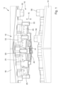
- the Figures 1 to 5 , 7 and 8 show a first exemplary embodiment of the punching tool 11 according to the invention for cutting plastic-based film elements 12.
- the punching tool 11 according to the invention is described below using a three-dimensional PET-based film element 12 as an example, which can be, for example, a yogurt cup.
- a three-dimensional PET-based film element 12 can be, for example, a yogurt cup.
- the punching tool 11 according to the invention can be used to process completely different plastic-based film elements 12, for example, two-dimensional plastic films.
- the punching tool 11 according to the invention can be used to process two- or three-dimensional PE, PP, PLA, or PVC-based film elements.
- the aim of the punching process of the plastic, especially PET-based film elements 12 is to assemble the film elements 12 from a virtually endless raw strand into individual groups or individual elements.
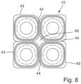
- An example of this is Figure 8 a group of four yogurt cups is shown.
- the punching tool 11 has a punching unit 13, which represents the movable part of the punching tool 11.
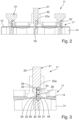
- a die 14 for receiving the film element 12 to be processed is arranged opposite the punching unit 13, wherein the punching unit 13 is moved relative to the die 14 during a punching stroke in a stroke direction 15 between a starting position 16 ( Figure 1 ) and a processing position 17 ( Figures 2 and 3) is mounted relatively movably.
- the punching unit 13 has a base plate 18, which is shown as an example in a rectangular shape.
- Several functional components of the punching unit 13 are attached to the base plate 18.
- Functional components include several punching knife modules 19, one of which is shown as an example in Figure 7
- the punching knife module 19 has an exemplary cube-shaped base body 20 on which a knife carrier 21 is movably mounted.
- the knife carrier 21 has a guide section 22 mounted on the base body 20 and a bearing section 23 forming the free end of the knife carrier 21, on which a flat and planar knife seat 24 for an associated punching knife 25a is formed.
- the punching knife 25a is detachably fastened to the associated knife seat 24 by means of fastening means.
- fastening means shown are fastening screws 26a, 26b, which penetrate associated through holes 27a, 27b in the punching knife and the associated recesses (not shown) are countersunk in the bearing section of the knife carrier 21.
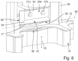
- the punching knife 25a, 25b has a knife base 30 on which, as shown particularly in the Figures 4 to 6 shown, the through holes 27a, 27b are located, which penetrate the knife base 30 transversely to the stroke direction 15.
- the punching knife also has a cutting wedge 31 which tapers in the stroke direction to a cutting edge 32.
- the cutting wedge 31 is formed by a wedge inner surface 33 and a wedge outer surface 34, wherein the wedge outer surface 34 in the example is inclined to the stroke direction 15, while the wedge inner surface 33 runs substantially parallel to the stroke direction.
- the die 14 has a knife cavity 35 which has a die edge 36 associated with the wedge inner surface 33, wherein the wedge inner surface 33 moves along the die edge 36 during the punching stroke at a certain distance which is determined by the thickness of the adjusting disk 29 transversely to the stroke direction.
- the cutting edge 32 of the punching knife 25a is contoured such that it has an edge portion 37a, 37b which is inclined with respect to a reference line 38 perpendicular to the stroke direction 15.
- the cutting edge 32 has two edge sections 37a, 37b arranged at an angle to one another, which together form a wedge shape. This creates a wedge tip 40 or cutting tip approximately centrally with respect to the edge length 39, which first strikes the foil element 12 to be processed during the punching stroke.
- the characteristic contour of the cutting edge 32 according to the first embodiment is expediently produced in the manner of a diamond cut. As shown in particular in Figure 4 or 5, in this case, not only is the cutting edge 32 ground with the two edge sections 37a, 37b, but the grinding also extends into the wedge outer surface 34. For example, two flank surfaces 41a, 41b, also tapering towards each other in a wedge shape, are formed here.
- the Figure 6 shows a second embodiment of the punching tool 11 according to the invention.
- the second embodiment differs from the previously described first embodiment in the different design of the punching blade 25b, which in this case has a differently contoured cutting edge 32.
- the cutting edge 32 has several edge sections 37 that together form a wave-shaped contour. This can be achieved, for example, in the manner of a "bread knife grind.”
- the cutting wedges 31 of the punching knives 37a, 37b plunge into the foil element 12 to be processed and, depending on their immersion depth, create a cutting line 43 or a breaking line 44 in the foil system 12 along an edge length of the cutting edge 32.
- a height adjustment device (not shown) belonging to the punching unit 13 is used to adjust the immersion depth of the punching knives 25a, 25b.
- the height adjustment device allows the punching knives 25a, 25b to be moved between a cutting height position 45, in which the punching knives 25a, 25b create a cutting line 43 during the punching stroke, and a perforation height position that is further away from the die 14 than the cutting height position 45 in the starting position 16.
- 46 in which the punching knives 25a, 25b create a breaking line during the punching stroke.
- punching knives 25b with a wave-shaped contour these are also suitable for forming breaking lines 44.
- the height adjustment device is a control device (not shown) that allows individual control of the punching knife modules 19, allowing them to be moved either to the cutting height position 45 or the perforation height position 46. This allows for a completely different grouping of punching knives that generate cutting lines 43 and punching knives that generate perforation lines 44 to be set in order to produce the foil element to be processed in a completely different way.
- the height adjustment unit can, for example, have a switching system that allows for fluidic, for example pneumatic, height adjustment of the punching knife modules 19.
- the height adjustment device comprises height adjustment units, of which Figure 7 One is shown as an example.
- the height adjustment units 47 include the base body 20 of the punching knife module 19, already described above, on which the knife carrier 21 is movably mounted in the stroke direction 15 via an adjustment drive 48, which also belongs to the height adjustment unit 47.
- the adjustment drive 48 is designed as a spindle drive.
- the punching unit 13 also includes other functional units.
- the punching unit 13 has a hold-down device 49 with at least one hold-down clamp that fixes the foil element to be processed in the processing position 17 on the die 14.
- the punching unit 13 comprises a plurality of, in the example, star-shaped contour punches 50 for punching out a surface section 60 ( Fig.8 ) of the film element 12 to be processed.
- a contour punch 50 is arranged between adjacent punching blades 27a, 27b.
- the undersides 51 of the contour punches are positioned closer to the die 14 in the starting position 16 than the cutting edges 32 of the punching blades 25a, 25b.
- the contour punches 50 precede the punching blades during the punching stroke and penetrate into the plastic material of the film element 12 before the punching blades 25a, 25b.
- the die 14 has a plurality of contour cavities 52 which interact with the associated contour punches 50 during the punching stroke and into which the contour punches 50 can be inserted, wherein the contour cavities each adjoin adjacent knife cavities 35 for the punching knives 25a, 25b.
- the contour cavities 52 are each surrounded by support sections 53 supporting the film element 12 to be processed.
- a step 54 is formed between the support sections 53 and the knife cavities.
- a further functional unit of the punching unit 13 is a stop element 55 arranged on the base plate 18, which interacts with a counter-stop element 56 arranged on the die 14 in such a way that the stop element 55 located on the movable punching unit 13 strikes the counter-stop element 56 to limit the punching stroke.
- a stop element 55 arranged on the base plate 18, which interacts with a counter-stop element 56 arranged on the die 14 in such a way that the stop element 55 located on the movable punching unit 13 strikes the counter-stop element 56 to limit the punching stroke.
- Fig. 1 shown are several pairs of stop elements 55 and counter-stop elements 56 distributed over the surface of base plate 18 on the one hand and die 14.
- a key aspect is that, before the first use of the punching tool, the distance between the wedge inner surface 33 and the die edge 36 of each individual punching blade 25a, 25b can be precisely adjusted using appropriately selected shims 29. This distance does not need to be readjusted during operation of the punching tool 11.
- the punching blades 25a, 25b can be replaced, for example, in the event of wear, but the shims remain in place, so that even with newly installed punching blades, the correct distance between the wedge inner surface 33 and the die edge 36 is always set.
- the packaging to be processed for the plastic-based film element 12 is first determined.
- An example of this is a group of four, such as four yogurt cups, which are still connected by break lines 44 and can then be separated from each other by tearing.
- groups of punching knives are then moved to the cutting height position 45, so that a cutting line 43 is created during the punching stroke, and other groups are moved to the perforation height position 46, so that break lines 44 are created here during the punching stroke.
- the punching unit 13 With the punching knives 25a, 25b correctly positioned at the height, moves downwards towards the die 14, on which the film element 12 to be processed was previously deposited.
- edge sections 42a, 42b of the cutting edges 32 of the punching knives 25, 25b are aligned obliquely to a reference line 38 oriented perpendicular to the stroke direction, cutting is not carried out simultaneously over the entire edge length, but gradually.
- the wedge tip 40 first penetrates the material of the film element 12.
- the cutting line 43 is therefore created in the manner of a pulling cut, which significantly reduces the forces on the punching knives 25a, 25b.
- the punching knives 25a, 25b move into the associated knife cavity 35 in the die 14.
- the punching knives 25b located at the perforation height 46 move into the foil element 12 to be processed, but do not penetrate as deeply, creating the previously described break line 44.
- the contour punches 50 Before the punching blades 25a, 25b, the contour punches 50 have already moved into the film element 12 to be processed and have punched out a star-shaped surface section 60, for example. Because the cutting line 43 is formed over the entire cutting edge 32 of the punching blade, the transition between the punched surface section 60 and the cutting line 43 is free of disruptive transitions, such as barb-like material residues. This is also supported by the fact that the film element 12 to be processed is supported in the area of the contour cavities 52 by the adjacent support sections 53.
Landscapes
- Life Sciences & Earth Sciences (AREA)
- Forests & Forestry (AREA)
- Engineering & Computer Science (AREA)
- Mechanical Engineering (AREA)
- Perforating, Stamping-Out Or Severing By Means Other Than Cutting (AREA)
Claims (14)
- Outil de poinçonnage pour la découpe d'éléments de film à base de matière plastique (12), avec une unité de poinçonnage (13) qui présente plusieurs porte-couteaux (21), auxquels respectivement au moins un couteau de poinçonnage (25a, 25b) présentant un coin de coupe (31) s'effilant vers un bord de coupe (32) est fixé, et avec une matrice (14) associée à l'unité de poinçonnage (13), opposée à celle-ci pour recevoir l'élément de film (12) à usiner, dans lequel l'unité de poinçonnage (13) est logée de manière relativement mobile par rapport à la matrice (14) lors d'une course de poinçonnage se produisant dans un sens de course (15) entre une position de départ (16) et une position d'usinage (17), dans lequel les coins de coupe (31) des couteaux de poinçonnage (25a, 25b) plongent dans la position d'usinage (17) dans l'élément de film à usiner (12) et générent en fonction de leur profondeur d'immersion le long d'une longueur du bord de coupe (32) une ligne de coupe (43) ou une ligne de rupture (44) dans le système de film (12), dans lequel les bords de coupe (32) des couteaux de poinçonnage (25a, 25b) sont profilés de sorte qu'ils présentent chacun une section de bord (37 ; 37a, 37b) qui est inclinée par rapport à une ligne de référence (38) perpendiculaire au sens de course (15), dans lequel les coins de coupe (31) sont formés respectivement d'une surface intérieure de coin (33) et d'une surface extérieure de coin (34) et la matrice présente une cavité de couteau (35) qui présente un bord de matrice (36) associé à la surface intérieure de coin (33), dans lequel la surface intérieure de coin (33) se déplace lors de la course de poinçonnage à une certaine distance qui est déterminée par l'épaisseur d'un disque d'ajustage (29) transversalement au sens de la course, le long du bord de la matrice (36).
- Outil de poinçonnage selon la revendication 1, caractérisé en ce que le bord de coupe (32) présente deux sections de bord (37a, 37b) agencées à angle droit l'une par rapport à l'autre, qui forment ensemble une forme de coin.
- Outil de poinçonnage selon la revendication 1, caractérisé en ce que le bord de coupe (32) présente plusieurs sections de bord (37) qui forment ensemble un contour ondulé.
- Outil de poinçonnage selon la revendication 1, caractérisé en ce que le bord de coupe (32) présente plusieurs sections de bord qui forment ensemble un contour en zigzag.
- Outil de poinçonnage selon l'une quelconque des revendications précédentes, caractérisé en ce que l'unité de poinçonnage (13) présente plusieurs poinçons de contour (50) par exemple en forme d'étoile pour le poinçonnage d'une section de surface de l'élément de film (12), dont la face inférieure (51) est positionnée dans la position de départ (16) plus près de la matrice (14) que les bords de coupe (32) des couteaux de poinçonnage (25a, 25b).
- Outil de poinçonnage selon l'une quelconque des revendications précédentes, caractérisé en ce que les couteaux de poinçonnage (25a, 25b) sont respectivement fixés de manière détachable à l'aide de moyens de fixation à un siège de couteau (24) du porte-couteaux (31) associé, dans lequel les moyens de fixation présentent un élément d'ajustement en particulier en forme de disque agencé entre le siège de couteau (24) et la surface intérieure de coin (33) pour le réglage de la distance entre le bord de matrice (36) et la surface intérieure de coin (33).
- Outil de poinçonnage selon l'une quelconque des revendications précédentes, caractérisé en ce que l'unité de poinçonnage (13) présente un dispositif de réglage en hauteur des couteaux de poinçonnage (25a, 25b) entre une position de hauteur de coupe (45), dans laquelle les couteaux de poinçonnage (25a, 25b) génèrent une ligne de coupe (43) lors de la course de poinçonnage et une position de hauteur de perforation (46) plus éloignée de la matrice (14) par rapport à la position de hauteur de coupe (45) dans la position de départ (16), dans laquelle les couteaux de poinçonnage (25a, 25b) génèrent une ligne de rupture (44) lors de la course de poinçonnage.
- Dispositif de poinçonnage selon la revendication 7, caractérisé en ce qu'au dispositif de réglage en hauteur est associé un dispositif de commande pour la commande individuelle des couteaux de poinçonnage (25a, 25b) afin de les déplacer au choix dans la position de hauteur de coupe (45) ou dans la position de hauteur de perforation (46).
- Outil de poinçonnage selon la revendication 7 ou 8, caractérisé en ce que le dispositif de réglage en hauteur présentent des unités d'ajustement en hauteur (47) pour l'ajustement individuel de la position en hauteur des couteaux de poinçonnage (25a, 25b) par rapport à la matrice (14), dans lequel les unités d'ajustement en hauteur (47) présentent de préférence respectivement un corps de base (20) relié à une plaque de base (18) de l'unité de poinçonnage (13), sur lequel le porte-couteaux (21) avec le couteau de poinçonnage dans le sens de la course (15) est logé de manière mobile par l'intermédiaire d'un entraînement de réglage (48).
- Outil de poinçonnage selon la revendication 9, caractérisé en ce que l'entraînement de réglage est conçu comme un entraînement à broche.
- Outil de poinçonnage selon l'une quelconque des revendications précédentes, caractérisé en ce que l'unité de poinçonnage (13) présente un dispositif de maintien (49) avec au moins un dispositif de maintien qui fixe l'élément de film (12) à usiner dans la position d'usinage (17) sur la matrice (14).
- Outil de poinçonnage selon l'une quelconque des revendications précédentes, caractérisé en ce que l'unité de poinçonnage (13) présente au moins un élément de butée (55), auquel au moins un élément de contre-butée (56) est associé au niveau de la matrice (14) de telle manière que l'élément de butée (55) heurte l'élément de contre-butée (56) lors de la course de poinçonnage pour limiter la course de levage de l'unité de poinçonnage (13).
- Outil de poinçonnage selon l'une quelconque des revendications 5 à 13, caractérisé en ce que la matrice (14) présente au moins une cavité de contour (52) interagissant lors de la course de poinçonnage avec le poinçon de contour (50) associé, dans laquelle le poinçon de contour (50) peut être rétracté, dans lequel la cavité de contour (52) est adjacente à des cavités de couteau (35) adjacentes pour les couteaux de poinçonnage (25a, 25b).
- Outil de poinçonnage selon la revendication 13, caractérisé en ce que les cavités de contour (52) sont respectivement entourées par des sections de support (53) supportant l'élément de film (12) à usiner.
Applications Claiming Priority (1)
| Application Number | Priority Date | Filing Date | Title |
|---|---|---|---|
| DE102020203752.3A DE102020203752B4 (de) | 2020-03-24 | 2020-03-24 | Stanzwerkzeug |
Publications (4)
| Publication Number | Publication Date |
|---|---|
| EP3885085A2 EP3885085A2 (fr) | 2021-09-29 |
| EP3885085A3 EP3885085A3 (fr) | 2021-12-15 |
| EP3885085C0 EP3885085C0 (fr) | 2025-04-30 |
| EP3885085B1 true EP3885085B1 (fr) | 2025-04-30 |
Family
ID=74870648
Family Applications (1)
| Application Number | Title | Priority Date | Filing Date |
|---|---|---|---|
| EP21161654.5A Active EP3885085B1 (fr) | 2020-03-24 | 2021-03-10 | Outil de poinçonnage |
Country Status (3)
| Country | Link |
|---|---|
| EP (1) | EP3885085B1 (fr) |
| DE (1) | DE102020203752B4 (fr) |
| ES (1) | ES3030383T3 (fr) |
Families Citing this family (5)
| Publication number | Priority date | Publication date | Assignee | Title |
|---|---|---|---|---|
| DE102021127601A1 (de) * | 2021-10-25 | 2023-04-27 | Slavoljub Stojanovski | Stanzvorrichtung |
| DE102022105660A1 (de) * | 2022-03-10 | 2023-09-14 | Rohrer Tools AG | Stanzwerkzeug |
| WO2023217487A1 (fr) * | 2022-05-12 | 2023-11-16 | Weber Maschinenbau Gmbh Breidenbach | Unité de séparation |
| FR3146611B1 (fr) * | 2023-03-13 | 2025-03-07 | Synerlink | Outil de découpe à butées mobiles |
| EP4650125A1 (fr) * | 2024-05-17 | 2025-11-19 | Rohrer Tools AG | Outil de poinçonnage |
Family Cites Families (6)
| Publication number | Priority date | Publication date | Assignee | Title |
|---|---|---|---|---|
| DE4208565A1 (de) * | 1991-11-29 | 1993-09-23 | Roeder & Spengler Stanz | Stanzmesser |
| DE4139283A1 (de) | 1991-11-29 | 1993-06-03 | Roeder & Spengler Stanz | Stanzmesser und vorrichtung zum stanzen |
| DE19506292A1 (de) | 1995-02-23 | 1996-08-29 | Kiene Christel | Gerät zum Ausstanzen von Lichtbildern |
| DE202009001645U1 (de) | 2009-02-10 | 2009-04-30 | Bayerische Motoren Werke Aktiengesellschaft | Vorrichtung zum bedarfsweisen Erzeugen eines Durchbruchs in einem Ausstattungsteil eines Fahrzeugs |
| EP2594496B1 (fr) * | 2011-11-17 | 2015-04-08 | Cryovac, Inc. | Appareil de conditionnement comportant un découpeur pour découper un film |
| ES2786824B2 (es) * | 2019-04-10 | 2021-05-11 | Ind Tecnologicas De Mecanizacion Y Automatizacion S A | Envase multiple y maquina para su fabricacion |
-
2020
- 2020-03-24 DE DE102020203752.3A patent/DE102020203752B4/de active Active
-
2021
- 2021-03-10 EP EP21161654.5A patent/EP3885085B1/fr active Active
- 2021-03-10 ES ES21161654T patent/ES3030383T3/es active Active
Also Published As
| Publication number | Publication date |
|---|---|
| EP3885085C0 (fr) | 2025-04-30 |
| DE102020203752B4 (de) | 2021-10-07 |
| DE102020203752A1 (de) | 2021-09-30 |
| EP3885085A2 (fr) | 2021-09-29 |
| ES3030383T3 (en) | 2025-06-27 |
| EP3885085A3 (fr) | 2021-12-15 |
Similar Documents
| Publication | Publication Date | Title |
|---|---|---|
| EP3885085B1 (fr) | Outil de poinçonnage | |
| EP2701861B1 (fr) | Procédé et dispositif de fabrication de pièces embouties sans bride | |
| DE3623035C1 (de) | Verfahren und Vorrichtung zum Herstellen eines eine scharfe Schneidkante aufweisenden Stanzwerkzeugs | |
| EP1889696B1 (fr) | Appareil pour le poinçonage et méthode utilisant un tel appareil | |
| EP2903790B1 (fr) | Méthode et unité de outil pour le justage de la fente entre les parties de l'outil | |
| DE1918780C2 (de) | Verfahren und Vorrichtung zum Feinschneiden von Werkstücken aus Blech | |
| EP0125667A1 (fr) | Outil emporte-pièce pour acier en feuillard pour coupes de carton ou similaire | |
| EP4074478B1 (fr) | Outil de poinçonnage | |
| DE102015222178B4 (de) | Perforationssystem und Verfahren | |
| EP2886231A1 (fr) | Procédé de fabrication d'une pièce de carosserie formée par emboutissage | |
| EP1285405B1 (fr) | Dispositif de poinconnage de matieres plastiques | |
| DE4035792C1 (en) | Printed circuit board panel de-edging device - has two saw-blades mounted in bearingblockings which can be positionally adjusted | |
| EP0585576B1 (fr) | Machine à poinçonner | |
| EP1764194B1 (fr) | Poinçon et utilisation d'un tel poinçon | |
| EP1486302A1 (fr) | Système de presse pour poinçonner et former des fland d'une feuille de materiau | |
| EP4241946B1 (fr) | Outil de poinçonnage | |
| DE102017129367B4 (de) | Trägerelement zur Aufnahme von Stanzlinien, das Trägerelement umfassende Stanzform und Verfahren zur Herstellung der Stanzform | |
| EP4650125A1 (fr) | Outil de poinçonnage | |
| DE10322302B4 (de) | Anlage zur Herstellung von Platinen aus bandförmigem Material | |
| EP4303026B1 (fr) | Procédé et appareil de création de livret | |
| EP1555096A2 (fr) | Contre-outil pour la coupe de matériaux en bande et procédé pour couper transversalement un matériau en bande avec un tel contre-outil | |
| EP1649989A1 (fr) | Dispositif pour découper à la matrice ou plusieurs récipients dans une bande plastique | |
| EP1184127A1 (fr) | Dispositif de traitement des feuilles plats | |
| DE102021118127A1 (de) | Verfahren zur herstellung eines stanzwerkzeugs sowie zur herstellung eines puzzles mit demselben und entsprechendes stanzwerkzeug sowie stanzeinheit | |
| EP4263161A1 (fr) | Procédé, cellule de fabrication et feuille de placage |
Legal Events
| Date | Code | Title | Description |
|---|---|---|---|
| PUAI | Public reference made under article 153(3) epc to a published international application that has entered the european phase |
Free format text: ORIGINAL CODE: 0009012 |
|
| STAA | Information on the status of an ep patent application or granted ep patent |
Free format text: STATUS: THE APPLICATION HAS BEEN PUBLISHED |
|
| AK | Designated contracting states |
Kind code of ref document: A2 Designated state(s): AL AT BE BG CH CY CZ DE DK EE ES FI FR GB GR HR HU IE IS IT LI LT LU LV MC MK MT NL NO PL PT RO RS SE SI SK SM TR |
|
| PUAL | Search report despatched |
Free format text: ORIGINAL CODE: 0009013 |
|
| AK | Designated contracting states |
Kind code of ref document: A3 Designated state(s): AL AT BE BG CH CY CZ DE DK EE ES FI FR GB GR HR HU IE IS IT LI LT LU LV MC MK MT NL NO PL PT RO RS SE SI SK SM TR |
|
| RIC1 | Information provided on ipc code assigned before grant |
Ipc: B26F 1/44 20060101ALI20211109BHEP Ipc: B26F 1/40 20060101AFI20211109BHEP |
|
| STAA | Information on the status of an ep patent application or granted ep patent |
Free format text: STATUS: REQUEST FOR EXAMINATION WAS MADE |
|
| 17P | Request for examination filed |
Effective date: 20220609 |
|
| RBV | Designated contracting states (corrected) |
Designated state(s): AL AT BE BG CH CY CZ DE DK EE ES FI FR GB GR HR HU IE IS IT LI LT LU LV MC MK MT NL NO PL PT RO RS SE SI SK SM TR |
|
| GRAP | Despatch of communication of intention to grant a patent |
Free format text: ORIGINAL CODE: EPIDOSNIGR1 |
|
| STAA | Information on the status of an ep patent application or granted ep patent |
Free format text: STATUS: GRANT OF PATENT IS INTENDED |
|
| INTG | Intention to grant announced |
Effective date: 20240503 |
|
| RIN1 | Information on inventor provided before grant (corrected) |
Inventor name: LAUTZ, CARSTEN Inventor name: NICK, JUERGEN Inventor name: MOSER, AMOS |
|
| GRAJ | Information related to disapproval of communication of intention to grant by the applicant or resumption of examination proceedings by the epo deleted |
Free format text: ORIGINAL CODE: EPIDOSDIGR1 |
|
| STAA | Information on the status of an ep patent application or granted ep patent |
Free format text: STATUS: REQUEST FOR EXAMINATION WAS MADE |
|
| INTC | Intention to grant announced (deleted) | ||
| GRAP | Despatch of communication of intention to grant a patent |
Free format text: ORIGINAL CODE: EPIDOSNIGR1 |
|
| STAA | Information on the status of an ep patent application or granted ep patent |
Free format text: STATUS: GRANT OF PATENT IS INTENDED |
|
| INTG | Intention to grant announced |
Effective date: 20241206 |
|
| GRAJ | Information related to disapproval of communication of intention to grant by the applicant or resumption of examination proceedings by the epo deleted |
Free format text: ORIGINAL CODE: EPIDOSDIGR1 |
|
| STAA | Information on the status of an ep patent application or granted ep patent |
Free format text: STATUS: REQUEST FOR EXAMINATION WAS MADE |
|
| GRAS | Grant fee paid |
Free format text: ORIGINAL CODE: EPIDOSNIGR3 |
|
| STAA | Information on the status of an ep patent application or granted ep patent |
Free format text: STATUS: GRANT OF PATENT IS INTENDED |
|
| GRAP | Despatch of communication of intention to grant a patent |
Free format text: ORIGINAL CODE: EPIDOSNIGR1 |
|
| GRAA | (expected) grant |
Free format text: ORIGINAL CODE: 0009210 |
|
| STAA | Information on the status of an ep patent application or granted ep patent |
Free format text: STATUS: THE PATENT HAS BEEN GRANTED |
|
| INTC | Intention to grant announced (deleted) | ||
| INTG | Intention to grant announced |
Effective date: 20250319 |
|
| AK | Designated contracting states |
Kind code of ref document: B1 Designated state(s): AL AT BE BG CH CY CZ DE DK EE ES FI FR GB GR HR HU IE IS IT LI LT LU LV MC MK MT NL NO PL PT RO RS SE SI SK SM TR |
|
| REG | Reference to a national code |
Ref country code: CH Ref legal event code: EP Ref country code: GB Ref legal event code: FG4D Free format text: NOT ENGLISH |
|
| REG | Reference to a national code |
Ref country code: DE Ref legal event code: R096 Ref document number: 502021007319 Country of ref document: DE |
|
| REG | Reference to a national code |
Ref country code: IE Ref legal event code: FG4D Free format text: LANGUAGE OF EP DOCUMENT: GERMAN |
|
| U01 | Request for unitary effect filed |
Effective date: 20250515 |
|
| U07 | Unitary effect registered |
Designated state(s): AT BE BG DE DK EE FI FR IT LT LU LV MT NL PT RO SE SI Effective date: 20250521 |
|
| REG | Reference to a national code |
Ref country code: ES Ref legal event code: FG2A Ref document number: 3030383 Country of ref document: ES Kind code of ref document: T3 Effective date: 20250627 |
|
| PG25 | Lapsed in a contracting state [announced via postgrant information from national office to epo] |
Ref country code: NO Free format text: LAPSE BECAUSE OF FAILURE TO SUBMIT A TRANSLATION OF THE DESCRIPTION OR TO PAY THE FEE WITHIN THE PRESCRIBED TIME-LIMIT Effective date: 20250730 Ref country code: GR Free format text: LAPSE BECAUSE OF FAILURE TO SUBMIT A TRANSLATION OF THE DESCRIPTION OR TO PAY THE FEE WITHIN THE PRESCRIBED TIME-LIMIT Effective date: 20250731 |
|
| PG25 | Lapsed in a contracting state [announced via postgrant information from national office to epo] |
Ref country code: PL Free format text: LAPSE BECAUSE OF FAILURE TO SUBMIT A TRANSLATION OF THE DESCRIPTION OR TO PAY THE FEE WITHIN THE PRESCRIBED TIME-LIMIT Effective date: 20250430 |
|
| PG25 | Lapsed in a contracting state [announced via postgrant information from national office to epo] |
Ref country code: HR Free format text: LAPSE BECAUSE OF FAILURE TO SUBMIT A TRANSLATION OF THE DESCRIPTION OR TO PAY THE FEE WITHIN THE PRESCRIBED TIME-LIMIT Effective date: 20250430 |
|
| PG25 | Lapsed in a contracting state [announced via postgrant information from national office to epo] |
Ref country code: RS Free format text: LAPSE BECAUSE OF FAILURE TO SUBMIT A TRANSLATION OF THE DESCRIPTION OR TO PAY THE FEE WITHIN THE PRESCRIBED TIME-LIMIT Effective date: 20250731 |
|
| PG25 | Lapsed in a contracting state [announced via postgrant information from national office to epo] |
Ref country code: IS Free format text: LAPSE BECAUSE OF FAILURE TO SUBMIT A TRANSLATION OF THE DESCRIPTION OR TO PAY THE FEE WITHIN THE PRESCRIBED TIME-LIMIT Effective date: 20250830 |
|
| PG25 | Lapsed in a contracting state [announced via postgrant information from national office to epo] |
Ref country code: SM Free format text: LAPSE BECAUSE OF FAILURE TO SUBMIT A TRANSLATION OF THE DESCRIPTION OR TO PAY THE FEE WITHIN THE PRESCRIBED TIME-LIMIT Effective date: 20250430 |
|
| PG25 | Lapsed in a contracting state [announced via postgrant information from national office to epo] |
Ref country code: CZ Free format text: LAPSE BECAUSE OF FAILURE TO SUBMIT A TRANSLATION OF THE DESCRIPTION OR TO PAY THE FEE WITHIN THE PRESCRIBED TIME-LIMIT Effective date: 20250430 |
|
| PG25 | Lapsed in a contracting state [announced via postgrant information from national office to epo] |
Ref country code: SK Free format text: LAPSE BECAUSE OF FAILURE TO SUBMIT A TRANSLATION OF THE DESCRIPTION OR TO PAY THE FEE WITHIN THE PRESCRIBED TIME-LIMIT Effective date: 20250430 |
|
| PLBE | No opposition filed within time limit |
Free format text: ORIGINAL CODE: 0009261 |
|
| STAA | Information on the status of an ep patent application or granted ep patent |
Free format text: STATUS: NO OPPOSITION FILED WITHIN TIME LIMIT |
|
| REG | Reference to a national code |
Ref country code: CH Ref legal event code: L10 Free format text: ST27 STATUS EVENT CODE: U-0-0-L10-L00 (AS PROVIDED BY THE NATIONAL OFFICE) Effective date: 20260311 |
|
| U20 | Renewal fee for the european patent with unitary effect paid |
Year of fee payment: 6 Effective date: 20260205 |
|
| 26N | No opposition filed |
Effective date: 20260202 |
|
| PGFP | Annual fee paid to national office [announced via postgrant information from national office to epo] |
Ref country code: GB Payment date: 20260317 Year of fee payment: 6 |