EP4237389B1 - Verfahren zur herstellung einer turbomaschinenschaufel aus einem verbundstoff - Google Patents
Verfahren zur herstellung einer turbomaschinenschaufel aus einem verbundstoff Download PDFInfo
- Publication number
- EP4237389B1 EP4237389B1 EP21816123.0A EP21816123A EP4237389B1 EP 4237389 B1 EP4237389 B1 EP 4237389B1 EP 21816123 A EP21816123 A EP 21816123A EP 4237389 B1 EP4237389 B1 EP 4237389B1
- Authority
- EP
- European Patent Office
- Prior art keywords
- preform
- consolidated
- ceramic fibers
- blade
- fibrous
- Prior art date
- Legal status (The legal status is an assumption and is not a legal conclusion. Google has not performed a legal analysis and makes no representation as to the accuracy of the status listed.)
- Active
Links
Images




Classifications
-
- C—CHEMISTRY; METALLURGY
- C04—CEMENTS; CONCRETE; ARTIFICIAL STONE; CERAMICS; REFRACTORIES
- C04B—LIME, MAGNESIA; SLAG; CEMENTS; COMPOSITIONS THEREOF, e.g. MORTARS, CONCRETE OR LIKE BUILDING MATERIALS; ARTIFICIAL STONE; CERAMICS; REFRACTORIES; TREATMENT OF NATURAL STONE
- C04B35/00—Shaped ceramic products characterised by their composition; Ceramics compositions; Processing powders of inorganic compounds preparatory to the manufacturing of ceramic products
- C04B35/71—Ceramic products containing macroscopic reinforcing agents
- C04B35/78—Ceramic products containing macroscopic reinforcing agents containing non-metallic materials
- C04B35/80—Fibres, filaments, whiskers, platelets, or the like
-
- B—PERFORMING OPERATIONS; TRANSPORTING
- B29—WORKING OF PLASTICS; WORKING OF SUBSTANCES IN A PLASTIC STATE IN GENERAL
- B29B—PREPARATION OR PRETREATMENT OF THE MATERIAL TO BE SHAPED; MAKING GRANULES OR PREFORMS; RECOVERY OF PLASTICS OR OTHER CONSTITUENTS OF WASTE MATERIAL CONTAINING PLASTICS
- B29B11/00—Making preforms
- B29B11/14—Making preforms characterised by structure or composition
- B29B11/16—Making preforms characterised by structure or composition comprising fillers or reinforcement
-
- B—PERFORMING OPERATIONS; TRANSPORTING
- B32—LAYERED PRODUCTS
- B32B—LAYERED PRODUCTS, i.e. PRODUCTS BUILT-UP OF STRATA OF FLAT OR NON-FLAT, e.g. CELLULAR OR HONEYCOMB, FORM
- B32B18/00—Layered products essentially comprising ceramics, e.g. refractory products
-
- C—CHEMISTRY; METALLURGY
- C04—CEMENTS; CONCRETE; ARTIFICIAL STONE; CERAMICS; REFRACTORIES
- C04B—LIME, MAGNESIA; SLAG; CEMENTS; COMPOSITIONS THEREOF, e.g. MORTARS, CONCRETE OR LIKE BUILDING MATERIALS; ARTIFICIAL STONE; CERAMICS; REFRACTORIES; TREATMENT OF NATURAL STONE
- C04B37/00—Joining burned ceramic articles with other burned ceramic articles or other articles by heating
- C04B37/001—Joining burned ceramic articles with other burned ceramic articles or other articles by heating directly with other burned ceramic articles
-
- F—MECHANICAL ENGINEERING; LIGHTING; HEATING; WEAPONS; BLASTING
- F01—MACHINES OR ENGINES IN GENERAL; ENGINE PLANTS IN GENERAL; STEAM ENGINES
- F01D—NON-POSITIVE DISPLACEMENT MACHINES OR ENGINES, e.g. STEAM TURBINES
- F01D25/00—Component parts, details, or accessories, not provided for in, or of interest apart from, other groups
- F01D25/005—Selecting particular materials
-
- F—MECHANICAL ENGINEERING; LIGHTING; HEATING; WEAPONS; BLASTING
- F01—MACHINES OR ENGINES IN GENERAL; ENGINE PLANTS IN GENERAL; STEAM ENGINES
- F01D—NON-POSITIVE DISPLACEMENT MACHINES OR ENGINES, e.g. STEAM TURBINES
- F01D5/00—Blades; Blade-carrying members; Heating, heat-insulating, cooling or antivibration means on the blades or the members
- F01D5/12—Blades
- F01D5/28—Selecting particular materials; Particular measures relating thereto; Measures against erosion or corrosion
- F01D5/282—Selecting composite materials, e.g. blades with reinforcing filaments
-
- F—MECHANICAL ENGINEERING; LIGHTING; HEATING; WEAPONS; BLASTING
- F01—MACHINES OR ENGINES IN GENERAL; ENGINE PLANTS IN GENERAL; STEAM ENGINES
- F01D—NON-POSITIVE DISPLACEMENT MACHINES OR ENGINES, e.g. STEAM TURBINES
- F01D5/00—Blades; Blade-carrying members; Heating, heat-insulating, cooling or antivibration means on the blades or the members
- F01D5/12—Blades
- F01D5/28—Selecting particular materials; Particular measures relating thereto; Measures against erosion or corrosion
- F01D5/284—Selection of ceramic materials
-
- C—CHEMISTRY; METALLURGY
- C04—CEMENTS; CONCRETE; ARTIFICIAL STONE; CERAMICS; REFRACTORIES
- C04B—LIME, MAGNESIA; SLAG; CEMENTS; COMPOSITIONS THEREOF, e.g. MORTARS, CONCRETE OR LIKE BUILDING MATERIALS; ARTIFICIAL STONE; CERAMICS; REFRACTORIES; TREATMENT OF NATURAL STONE
- C04B2235/00—Aspects relating to ceramic starting mixtures or sintered ceramic products
- C04B2235/02—Composition of constituents of the starting material or of secondary phases of the final product
- C04B2235/50—Constituents or additives of the starting mixture chosen for their shape or used because of their shape or their physical appearance
- C04B2235/52—Constituents or additives characterised by their shapes
- C04B2235/5208—Fibers
- C04B2235/5252—Fibers having a specific pre-form
- C04B2235/5256—Two-dimensional, e.g. woven structures
-
- C—CHEMISTRY; METALLURGY
- C04—CEMENTS; CONCRETE; ARTIFICIAL STONE; CERAMICS; REFRACTORIES
- C04B—LIME, MAGNESIA; SLAG; CEMENTS; COMPOSITIONS THEREOF, e.g. MORTARS, CONCRETE OR LIKE BUILDING MATERIALS; ARTIFICIAL STONE; CERAMICS; REFRACTORIES; TREATMENT OF NATURAL STONE
- C04B2235/00—Aspects relating to ceramic starting mixtures or sintered ceramic products
- C04B2235/60—Aspects relating to the preparation, properties or mechanical treatment of green bodies or pre-forms
- C04B2235/612—Machining
-
- C—CHEMISTRY; METALLURGY
- C04—CEMENTS; CONCRETE; ARTIFICIAL STONE; CERAMICS; REFRACTORIES
- C04B—LIME, MAGNESIA; SLAG; CEMENTS; COMPOSITIONS THEREOF, e.g. MORTARS, CONCRETE OR LIKE BUILDING MATERIALS; ARTIFICIAL STONE; CERAMICS; REFRACTORIES; TREATMENT OF NATURAL STONE
- C04B2237/00—Aspects relating to ceramic laminates or to joining of ceramic articles with other articles by heating
- C04B2237/30—Composition of layers of ceramic laminates or of ceramic or metallic articles to be joined by heating, e.g. Si substrates
- C04B2237/32—Ceramic
- C04B2237/36—Non-oxidic
- C04B2237/365—Silicon carbide
-
- C—CHEMISTRY; METALLURGY
- C04—CEMENTS; CONCRETE; ARTIFICIAL STONE; CERAMICS; REFRACTORIES
- C04B—LIME, MAGNESIA; SLAG; CEMENTS; COMPOSITIONS THEREOF, e.g. MORTARS, CONCRETE OR LIKE BUILDING MATERIALS; ARTIFICIAL STONE; CERAMICS; REFRACTORIES; TREATMENT OF NATURAL STONE
- C04B2237/00—Aspects relating to ceramic laminates or to joining of ceramic articles with other articles by heating
- C04B2237/30—Composition of layers of ceramic laminates or of ceramic or metallic articles to be joined by heating, e.g. Si substrates
- C04B2237/32—Ceramic
- C04B2237/38—Fiber or whisker reinforced
-
- F—MECHANICAL ENGINEERING; LIGHTING; HEATING; WEAPONS; BLASTING
- F05—INDEXING SCHEMES RELATING TO ENGINES OR PUMPS IN VARIOUS SUBCLASSES OF CLASSES F01-F04
- F05D—INDEXING SCHEME FOR ASPECTS RELATING TO NON-POSITIVE-DISPLACEMENT MACHINES OR ENGINES, GAS-TURBINES OR JET-PROPULSION PLANTS
- F05D2230/00—Manufacture
- F05D2230/10—Manufacture by removing material
-
- F—MECHANICAL ENGINEERING; LIGHTING; HEATING; WEAPONS; BLASTING
- F05—INDEXING SCHEMES RELATING TO ENGINES OR PUMPS IN VARIOUS SUBCLASSES OF CLASSES F01-F04
- F05D—INDEXING SCHEME FOR ASPECTS RELATING TO NON-POSITIVE-DISPLACEMENT MACHINES OR ENGINES, GAS-TURBINES OR JET-PROPULSION PLANTS
- F05D2300/00—Materials; Properties thereof
- F05D2300/20—Oxide or non-oxide ceramics
-
- F—MECHANICAL ENGINEERING; LIGHTING; HEATING; WEAPONS; BLASTING
- F05—INDEXING SCHEMES RELATING TO ENGINES OR PUMPS IN VARIOUS SUBCLASSES OF CLASSES F01-F04
- F05D—INDEXING SCHEME FOR ASPECTS RELATING TO NON-POSITIVE-DISPLACEMENT MACHINES OR ENGINES, GAS-TURBINES OR JET-PROPULSION PLANTS
- F05D2300/00—Materials; Properties thereof
- F05D2300/60—Properties or characteristics given to material by treatment or manufacturing
- F05D2300/603—Composites; e.g. fibre-reinforced
-
- F—MECHANICAL ENGINEERING; LIGHTING; HEATING; WEAPONS; BLASTING
- F05—INDEXING SCHEMES RELATING TO ENGINES OR PUMPS IN VARIOUS SUBCLASSES OF CLASSES F01-F04
- F05D—INDEXING SCHEME FOR ASPECTS RELATING TO NON-POSITIVE-DISPLACEMENT MACHINES OR ENGINES, GAS-TURBINES OR JET-PROPULSION PLANTS
- F05D2300/00—Materials; Properties thereof
- F05D2300/60—Properties or characteristics given to material by treatment or manufacturing
- F05D2300/603—Composites; e.g. fibre-reinforced
- F05D2300/6033—Ceramic matrix composites [CMC]
-
- Y—GENERAL TAGGING OF NEW TECHNOLOGICAL DEVELOPMENTS; GENERAL TAGGING OF CROSS-SECTIONAL TECHNOLOGIES SPANNING OVER SEVERAL SECTIONS OF THE IPC; TECHNICAL SUBJECTS COVERED BY FORMER USPC CROSS-REFERENCE ART COLLECTIONS [XRACs] AND DIGESTS
- Y02—TECHNOLOGIES OR APPLICATIONS FOR MITIGATION OR ADAPTATION AGAINST CLIMATE CHANGE
- Y02T—CLIMATE CHANGE MITIGATION TECHNOLOGIES RELATED TO TRANSPORTATION
- Y02T50/00—Aeronautics or air transport
- Y02T50/60—Efficient propulsion technologies, e.g. for aircraft
Definitions
- This presentation relates to a method of manufacturing a turbomachine blade made of composite material, in particular for an aeronautical engine.
- WO2014/076408 which describes a fiber preform for a turbomachine blade obtained by monobloc three-dimensional weaving.
- three-dimensional weaving can be a complex process.
- WO 2010/077401 discloses a method of manufacturing a turbomachine blade made of ceramic matrix composite material.
- the distributor is subjected to forces related to the aerodynamic flow in the vein and to the piston effect on the casing under the distributor due to the pressure difference between the upstream and downstream cavities under the distributor. These forces can create a moment around the attachment between the distributor and the casing and therefore reduce the mechanical properties of the turbomachine.
- a preform is said to be in the consolidated state when it has undergone a consolidation step during which its initial porosity has been partially filled by a deposit of a consolidation phase, this preform in the consolidated state retaining a residual porosity which can be completely or partially filled during the subsequent co-densification step.
- consolidation methods are detailed below.
- a preform is said to be in the unconsolidated state when it is devoid of such a consolidation phase.
- a preform in the unconsolidated state may be in the dry state or be impregnated with a precursor of a material of a consolidation phase, the consolidation not being finalized in the latter case due to the non-transformation of the precursor into a consolidation phase.
- first and a second preform each supporting a limited number of functions so as to make them both easily formable and to assemble these two preforms in order to form the preform constituting the fiber reinforcement of the blade to be manufactured.
- the blade manufacturing process is significantly simplified.
- the consolidated strand ensures the continuity of mechanical and thermal loads from the platforms to the blade of the blade.
- the shear forces are transmitted from the first consolidated preform to the second consolidated preform thanks to the presence of the consolidated strand. Its mechanical strength is improved, which thus gives good mechanical properties to the manufactured blade so that the turbine blade forms a homogeneous system from the material point of view.
- the ceramic fiber strand can be obtained with twisted wires or braided wires.
- the second fibrous preform forming a platform preform can also form a preform for other parts of the blade connected to the platform, for example the stilt and/or the bulb of a moving blade and/or the wipers.
- the step of producing the first fiber preform or the second fiber preform may be followed by a step of shaping the fiber preform.
- the blade thus produced can be used in a turbine or in a turbomachine compressor.
- the method may comprise the production of several second fiber preforms. For example, a second fiber preform forming a platform preform at the blade head and a second fiber preform forming a platform preform at the blade root.
- the consolidated strand may be disposed in a groove formed in at least one of the first consolidated preform or the second consolidated preform.
- the groove may be at least partially machined.
- the groove machining is carried out for fiber preforms having a thickness greater than or equal to 5 mm (millimeter).
- the groove may be at least partially formed during the step of making the first fiber preform and/or the second fiber preform.
- the formation of the groove during the step of producing the fibrous preforms is carried out for fibrous preforms having a thickness of less than 5 mm.
- the groove can be machined in a consolidated preform (the first or the second) and be formed during the step of producing the first or second fiber preform.
- the second consolidated preform may include two channels for inserting the consolidated strand into the groove.
- the channels may open onto an external face of the second consolidated preform.
- the second consolidated preform comprises an internal face and an external face, the internal face being intended to delimit a flow vein of the turbomachine and the external face being the face opposite the internal face.
- the channels may have an angle relative to the outer face greater than or equal to 1° and less than or equal to 20°.
- This angle makes it easier to insert and remove the strand from the channels.
- a portion of the consolidated strand may be removed prior to the co-densification step.
- the parts of the consolidated strand which protrude from the external face can be leveled before the co-densification step.
- a portion of the consolidated strand may be removed after the co-densification step.
- the portions of the consolidated strand that protrude from the external face may be retained during the co-densification step to promote the capillary rise of an infiltration liquid during the co-densification step. After co-densification, these portions may be removed by machining.
- the second consolidated preform may include a portion having an excess thickness, the portion having the excess thickness defining the housing.
- the first fibrous preform comprises multi-layer woven ceramic fibers, ceramic fiber webs, or unidirectional long ceramic fibers.
- Multi-layer weaving means weaving carried out between a plurality of layers of warp threads and a plurality of layers of weft threads, possibly followed by a shaping step and also braiding.
- the multilayer weaving steps of ceramic fibers can be followed by a step of shaping the fiber preform.
- the second fibrous preform comprises multi-layer woven ceramic fibers, ceramic fiber webs, unidirectional long ceramic fibers, or short ceramic fibers.
- Short fibres may have a length of between 50 ⁇ m and 5000 ⁇ m, for example between 50 ⁇ m and 1000 ⁇ m, for example between 100 ⁇ m and 500 ⁇ m, for example substantially 250 ⁇ m.
- an “average” dimension means the dimension given by the statistical particle size distribution to half the population, called d 50 .
- the ceramic fibers are silicon carbide fibers.
- the ceramic fibers used may be carbon or silicon carbide (SiC) fibers marketed under the name Nicalon TM , Hi-Nicalon or Hi-Nicalon TM Type S by the Japanese company Nippon Carbon and having, for example, a count (number of filaments) of 0.5K (500 filaments).
- SiC silicon carbide
- first and second fibrous preforms may each comprise, in particular be formed of, carbon threads.
- first fibrous preform may comprise, in particular be formed of, carbon threads and the second fibrous preform may comprise, in particular be formed of, ceramic threads such as silicon carbide threads.
- the first and second fibrous preforms may each comprise, in particular be formed of, ceramic threads such as silicon carbide threads.
- the turbomachine blade is a turbomachine stator.
- the turbomachine blade is a turbomachine moving blade.
- the turbomachine may be a turbojet.
- consolidation may be accomplished by deposition of a gas-deposited or liquid-deposited consolidation phase.
- the co-densification may be accomplished by a melt infiltration process.
- the molten composition for infiltration may include silicon.
- the ceramic fibers may be coated with an interphase layer, for example a boron nitride (BN) or pyrocarbon (PyC) interphase layer.
- an interphase layer for example a boron nitride (BN) or pyrocarbon (PyC) interphase layer.
- This interphase layer serves to deflect cracks in the ceramic matrix during use of the part.
- the interphase layer has, for example, a thickness of 500 nm.
- the interphase layer can also be coated with a protective layer, for example a layer of silicon carbide a few microns thick. This protective layer protects the interphase from potential chemical attacks by the molten composition during infiltration of the first preform and possibly the second preform.
- FIG. 1 represents, in section along a vertical plane passing through its main axis A, a dual-flow turbojet 10.
- the dual-flow turbojet 10 comprises, from upstream to downstream according to the circulation of the air flow, a fan 12, a low-pressure compressor 14, a high-pressure compressor 16, a combustion chamber 18, a high-pressure turbine 20, and a low-pressure turbine 22.
- the high pressure turbine 20 comprises a plurality of moving blades 26 rotating with the rotor and rectifiers 24 mounted on the stator.
- FIG 2 represents a rectifier portion 24 of a high-pressure turbine 22 of a turbomachine, for example a turbojet.
- the rectifier portion 24 comprises, in the example of the figure 2 , two blades 24A joined by respectively a platform 24B at the blade head, common to the two blades 24A and a platform 24C at the blade foot, common to the two blades 24A.
- FIG. 3 represents a rectifier 24 comprising a blade 24A, a platform 24B at the blade head and a platform 24C at the blade foot.
- FIG 4 represents a mobile blade 26 comprising a blade 26A, a platform 26B at the blade head and a platform 26C at the blade root. As shown in the figure 3 , the 26C platform at the foot of the blade is extended by a 26D stilt and a 26E bulb.
- the method 100 for manufacturing a turbomachine blade made of ceramic matrix composite material, in particular the rectifier 24 of the figure 3 , will be described with reference to the Figures 4 to 11 .
- the method 100 comprises a step 102 of producing a first fibrous preform 28A comprising ceramic fibers, the first fibrous preform 28A forming a blade preform.
- the method 100 comprises a step 104 of producing a second fibrous preform 28B comprising ceramic fibers, the second fibrous preform 28B comprising a housing 28D, the second fibrous preform 28B forming a platform preform, for example at the blade head.
- the method 100 comprises a step 104 of producing a second fibrous preform 28C comprising ceramic fibers, the second fibrous preform 28C comprising a housing 28E, the second fibrous preform 28C forming a platform preform, for example at the foot of a blade.
- the production step 104 can be repeated to form several second fibrous preforms, for example two second fibrous preforms, one forming a platform preform at the blade head and the other forming a platform preform at the blade foot.
- the first fiber preform 28A may be made by multilayer weaving of ceramic fibers to form a first fiber preform 28A in a single piece, by superimposing sheets of ceramic fibers or by superimposing unidirectional ceramic fibers. It is understood that the sheets and the unidirectional ceramic fibers may have a different orientation in each layer.
- the second fiber preform 28B, 28C can be made by multilayer weaving of ceramic fibers to form a second fiber preform 28A in a single piece, by superimposing sheets of ceramic fibers or by superimposing unidirectional ceramic fibers. It is understood that the sheets and the unidirectional ceramic fibers can have a different orientation in each layer.
- the second fiber preform 28B, 28C can be made with short fibers.
- the multilayer weaving steps of ceramic fibers may or may not be followed by respective steps of shaping the fiber preforms.
- the multi-layer weave produced may in particular be an "interlock" weave, i.e. a weave weave in which each layer of weft threads binds several layers of warp threads with all the threads of the same weft column having the same movement in the plane of the weave.
- Other types of multi-layer weave may be used. Different modes of multi-layer weaving that can be used are described in particular in the document WO2006/136755 .
- Weaving can be carried out with warp yarns extending in the longitudinal direction of the preforms, it being noted that weaving with weft yarns in this direction is also possible.
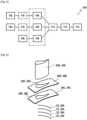
- the method 100 comprises a step 106 of producing a strand 32A of ceramic fibers, in the embodiment of the Figures 5 to 11 , four 32A strands of ceramic fibers.
- the 32A ceramic fiber strands can for example be obtained with twisted wires or braided wires.
- FIG. 6 represents the first fiber preform 28A forming a blade preform, the second fiber preform 28B forming a platform preform at the blade head, the second fiber preform 28C forming a platform preform at the blade foot and four strands of ceramic fibers 32A.
- the ceramic fibers of the first, second fiber preforms 28A, 28B, 28C and strands 32A are for example made of Hi-Nicalon TM Type S.
- the method 100 comprises a step 108 of consolidating the first fiber preform 28A, the second fiber preforms 28B, 28C and the four ceramic fiber strands 32A to form a first consolidated preform 30A in a single piece, two second consolidated preforms 30B, 30C in a single piece each each comprising a housing 30D, 30E and four consolidated strands 32, as shown in FIG. figure 6 .
- the consolidated strands 32 may have a diameter of approximately 3 mm.
- housing 30D of the second consolidated preform 30B forming the platform preform at the blade head corresponds, after consolidation, to the housing 28D of the second fibrous preform 28D forming the platform preform at the blade head.
- housing 30E of the second consolidated preform 30C forming a platform preform at the foot of the blade corresponds, after consolidation, to the housing 28E of the second fibrous preform 28E forming a platform preform at the foot of the blade.
- the fibrous preforms 28A, 28B, 28C and the ceramic fiber strands 32A are consolidated by depositing a consolidation phase in the porosity of the fibrous preforms 28A, 28B, 28C and the ceramic fiber strands 32A, this consolidation phase being deposited by gas or liquid means in a manner known per se.
- the consolidation steps 108 of the preforms and strands are shown as separate steps but the fibrous preforms and strands may be consolidated in a common consolidation step.
- the liquid process consists of impregnating the preform with a liquid composition containing a precursor of the material of the consolidation phase.
- the precursor is usually in the form of a polymer, such as a resin, optionally diluted in a solvent.
- the preform is placed in a mold that can be closed in a sealed manner. Then, the mold is closed and the liquid precursor of the consolidation phase (for example a resin) is injected into the mold in order to impregnate the preform.
- the transformation of the precursor into the consolidation phase is carried out by heat treatment, generally by heating the mold, after elimination of any solvent and crosslinking of the polymer.
- the heat treatment comprises a step of pyrolysis of the precursor to form the consolidation phase in ceramic material.
- liquid precursors of ceramic in particular SiC
- PCS polycarbosilane
- PTCS polytitanocarbosilane
- PSZ polysilazane
- the fiber preform is placed in an oven into which a reaction gas phase is admitted.
- the pressure and temperature prevailing in the oven and the composition of the gas phase are chosen so as to allow the diffusion of the gas phase within the porosity of the preform to form the consolidation phase by deposition, at the heart of the material in contact with the fibers, of a solid material resulting from a decomposition of a constituent of the gas phase or from a reaction between several constituents.
- the formation of a SiC consolidation phase can be obtained with methyltrichlorosilane (MTS) giving SiC by decomposition of the MTS.
- MTS methyltrichlorosilane
- the first consolidated preform 30A and the second consolidated preforms 30B, 30C may optionally be shaped, for example by machining.
- the method 100 comprises a step 110 of assembling the first consolidated preform 30A and the two second consolidated preforms 30B, 30C, by engagement and cooperation of the first consolidated preform 30A, respectively in the housing 30D, 30E of the two second consolidated preforms 30B, 30C, the consolidated strands 32 being interposed between the first consolidated preform 30A and each of the second consolidated preforms 30B, 30C, as shown in the figure 7 .
- first consolidated preform 30A is inserted into the housings 30D, 30E of the two second consolidated preforms 30B, 30C.
- the method 100 comprises a step of co-densification 112 of the assembly to form the turbomachine blade, for example the rectifier 24 of the figure 3 .
- a co-densification of the first and second preforms thus assembled is then carried out.
- the co-densification may be achieved by a melt infiltration process.
- fillers for example reactive fillers
- the fillers being for example chosen from SiC, Si 3 N 4 , C, B, and their mixtures.
- the introduction of the fillers can, for example, be carried out by slip casting ("Slurry cast"), by sub-micron powder aspiration (APS) or by an injection process of the resin injection molding process type ("Resin Transfer Molding" or "RTM”) in which a heat treatment is carried out after the injection to evaporate the liquid medium.
- the first and second preforms are then infiltrated with a molten infiltration composition.
- a molten infiltration composition comprising for example silicon in order to form a matrix and thus obtain the turbomachine blade.
- the infiltration composition may consist of molten silicon or alternatively be in the form of a molten alloy of silicon and one or more other constituents.
- the constituent(s) present in the silicon alloy may be chosen from B, Al, Mo, Ti, and mixtures thereof.
- reactive fillers substantially all of the reactive fillers may be consumed during the reaction between the infiltration composition and the reactive fillers. Alternatively, only a portion of the reactive fillers is consumed during this reaction.
- the molten infiltration carried out can make it possible to obtain a matrix by reaction between solid fillers, for example of type C, SiC or Si 3 N 4 introduced by slip or pre-impregnated, and a molten alloy based on silicon.
- the reaction can occur at a temperature greater than or equal to 1420°C.
- the wires of the first and second preforms may, before infiltration of the infiltration composition, have been coated with an interphase layer, for example in BN or BN doped with silicon, as well as a carbide layer, for example in SiC and/or Si 3 N 4 , for example produced by gas.
- an interphase layer for example in BN or BN doped with silicon
- a carbide layer for example in SiC and/or Si 3 N 4 , for example produced by gas.
- a first step of co-densification of the assembled first and second preforms may first be carried out by liquid densification, this type of process being as described above in relation to the step of consolidating the fibrous preforms.
- the step may then be followed by a second step of co-densification by chemical vapor infiltration (this type of process being as described above in relation to the step of consolidating the fibrous preforms) or by melt infiltration.
- the second step of co-densification is carried out in order to fill all or part of the residual porosity resulting after implementation of the first step of co-densification.
- a co-densification combining liquid and gaseous routes may advantageously make it possible to facilitate implementation, limit costs and manufacturing cycles while obtaining satisfactory characteristics for the intended use.
- a first step of co-densification of the first and second preforms assembled by chemical vapor infiltration can first be carried out.
- the step of co-densification by chemical vapor infiltration can be followed by a shaping step, for example by machining.
- a second step of co-densification can then be carried out by a melt infiltration process.
- a groove 38 can be machined (step 114) in the second consolidated preform 30B.
- This groove 38 is configured to at least partially receive a consolidated strand 32.
- the groove 38 is visible from the housing 30D of the second consolidated preform 30B forming a platform preform at the blade head.
- the second consolidated preform 30B forming a platform preform at the blade head comprises two channels 36 for inserting the consolidated strand 32 into the groove 38.
- the channels 36 open onto an external face 30B2 of the second consolidated preform 30B forming a platform preform at the blade head.
- the channels 36 form orifices 34 on the external face 30B2 of the second consolidated preform 30B forming a platform preform at the blade head.
- the channels 36 may have an angle ⁇ relative to the external face 30B2, the angle ⁇ being greater than or equal to 1° and less than or equal to 20°.
- the second consolidated preform 30B forming a platform preform at the blade head comprises an internal face 30B4, opposite the external face 30B2 and facing the first consolidated preform 30A. It is understood that the internal face 30B4 partly delimits the aerodynamic vein.
- the groove 38 is present in the thickness of the second consolidated preform 30B forming a platform preform at the blade head and the groove 38 is present at least so that a consolidated strand 32 can be interposed between the first consolidated preform 30A and the second consolidated preform 30B forming a platform preform at the blade head, on an intrados side and on an extrados side of the first consolidated preform 30A.
- a groove can also be machined in the second consolidated preform 30C forming a platform preform at the blade root.
- the channels 36 form orifices 34 on the external face 30C2 of the second consolidated preform 30C forming a platform preform at the blade root.
- the channels 36 can have an angle ⁇ relative to the external face 30C2, the angle ⁇ being greater than or equal to 1° and less than or equal to 20°.
- the second consolidated preform 30C forming a platform preform at the foot of the blade comprises an internal face 30C4, opposite the external face 30C2 and facing the first consolidated preform 30A. It is understood that the internal face 30C4 partly delimits the aerodynamic vein.
- the groove 38 may be machined in the first consolidated preform 30A, as schematically shown in FIG. figure 9 for the second consolidated preform 30C forming platform preform at the foot of the blade.
- the groove 38 may be formed during the step of producing the first fiber preform 28A and the second fiber preform 28B, 28C, by deformation of the fiber preforms, during a step 116 of forming the groove 38, as shown in FIG. figure 10 . This step of forming 116 the groove 38 is carried out before the step of consolidating 108 the fiber preform.
- the second consolidated preform 30C forming a platform preform at the foot of the blade may have a portion comprising an excess thickness 30C3 relative to a portion 30C1 of the second consolidated preform 30C, the portion comprising the excess thickness 30C3 delimiting the housing 30D, 30E, as shown in the figure 11 for the second consolidated preform 30C forming a platform preform at the blade root.
- the thickness is modified on the external face 30C2 of the second consolidated preform 30C forming a platform preform at the blade root in order to disturb the aerodynamic flow in the vein as little as possible.
- FIGS 9 to 11 represent the assembly of the first consolidated preform 30A with the second consolidated preform 30C forming a platform preform at the blade root. It is understood that these embodiments can be applied in a similar manner for the assembly of the first consolidated preform 30A with the second consolidated preform 30B forming a platform preform at the blade tip.
- groove 38 can be machined in one preform and formed in the other consolidated preform with which it is assembled.
- the formation of the groove 38 can also include the formation of the channels 36 in the preform.
- the fiber preform may include a groove formed in the fiber preform and a channel machining step 36.
- a portion of the consolidated strands 32 may be removed prior to the co-densification step 112.
- a portion of the consolidated strands 32 may be removed after the co-densification step 112.
- the portions of the consolidated strands 32 which protrude from the external face 30B2, 30C2 of the second consolidated preforms 30B, 30C may be retained during the co-densification step 112 to promote the capillary rise of an infiltration liquid during the co-densification step. After co-densification 112, these portions may be removed by machining.
Landscapes
- Engineering & Computer Science (AREA)
- Chemical & Material Sciences (AREA)
- Materials Engineering (AREA)
- Ceramic Engineering (AREA)
- Mechanical Engineering (AREA)
- General Engineering & Computer Science (AREA)
- Structural Engineering (AREA)
- Organic Chemistry (AREA)
- Composite Materials (AREA)
- Chemical Kinetics & Catalysis (AREA)
- Manufacturing & Machinery (AREA)
- Turbine Rotor Nozzle Sealing (AREA)
Claims (12)
- Verfahren (100) zur Herstellung einer Turbomaschinenschaufel aus Verbundmaterial mit keramischer Matrix, die ein Blatt und eine Plattform umfasst, wobei das Verfahren umfasst:- Verwirklichung (102) einer ersten Faservorform (28A) umfassend keramische Fasern, wobei die erste Faservorform (28A) die Vorform des Blatts bildet,- Verwirklichung (104) einer zweiten Faservorform (28B, 28C), die keramische Fasern umfasst, wobei die zweite Faservorform eine Aufnahme (28D, 28E) umfasst, wobei die zweite Faservorform (28B, 28C) die Vorform der Plattform bildet,- Verwirklichung (106) einer Litze aus keramischen Fasern (32A),- Verfestigung (108) der ersten Faservorform (28A) in einem Stück, der zweiten Faservorform (28B, 28C) in einem Stück und der Litze aus keramischen Fasern (32A), um eine erste verfestigte Vorform (30A), eine zweite verfestigte Vorform (30B, 30C), die eine Aufnahme (30D, 30E) umfasst, und eine verfestigte Litze (32) zu bilden,- Zusammenbau (110) der ersten verfestigten Vorform (30A) und der zweiten verfestigten Vorform (30B, 30C), durch Ineingriffbringen und Zusammenwirken der ersten verfestigten Vorform (30A) in die/mit der Aufnahme (30D, 30E), wobei die verfestigte Litze (32) zwischen der ersten verfestigten Vorform (30A) und der zweiten verfestigten Vorform (30B, 30C) eingelegt wird,- gemeinsame Verdichtung (112) der Anordnung, um die Turbomaschinenschaufel zu bilden.
- Verfahren (100) nach Anspruch 1, wobei die verfestigte Litze (32) in einer Nut (38) angeordnet wird, die in zumindest einer von der ersten verfestigten Vorform (30A) oder der zweiten verfestigten Vorform (30B, 30C) gebildet ist.
- Verfahren (100) nach Anspruch 2, wobei die Nut (38) zumindest zum Teil maschinell bearbeitet ist.
- Verfahren (100) nach Anspruch 2 oder 3, wobei die Nut (38) zumindest zum Teil während des Schritts der Verwirklichung der ersten Faservorform (28A) und/oder der zweiten Faservorform (28B, 28C) gebildet wird.
- Verfahren (100) nach einem der Ansprüche 2 bis 4, wobei die zweite verfestigte Vorform (30B, 30C) zwei Kanäle (36) zur Einführung der verfestigten Litze (32) in die Nut (38) umfasst.
- Verfahren (100) nach Anspruch 5, wobei die Kanäle (36) auf einer Außenseite (30B2, 30C2) der zweiten verfestigten Vorform (30B, 30C) ausmünden.
- Verfahren (100) nach Anspruch 6, wobei die Kanäle (36) einen Winkel (α) in Bezug auf die Außenseite (30B2, 30C2) von mehr als oder gleich 1° und weniger als oder gleich 20° aufweisen.
- Verfahren (100) nach einem der Ansprüche 1 bis 7, wobei ein Teil der verfestigten Litze (32) vor dem Schritt der gemeinsamen Verfestigung entfernt wird.
- Verfahren (100) nach einem der Ansprüche 1 bis 7, wobei ein Teil der verfestigten Litze (32) nach dem Schritt der gemeinsamen Verfestigung entfernt wird.
- Verfahren (100) nach einem der Ansprüche 1 bis 9, wobei die zweite verfestigte Vorform (30B, 30C) einen Teil umfasst, der eine Verdickung (30C3) beinhaltet, wobei der Teil, der die Verdickung (30C3) beinhaltet, die Aufnahme (30D, 30E) begrenzt.
- Verfahren (100) nach einem der Ansprüche 1 bis 10, wobei die erste Faservorform mehrlagig verwebte keramische Fasern, Matten aus keramischen Fasern oder lange unidirektionale keramische Fasern umfasst.
- Verfahren (100) nach einem der Ansprüche 1 bis 11, wobei die zweite Faservorform mehrlagig verwebte keramische Fasern, Matten aus keramischen Fasern, lange unidirektionale keramische Fasern oder kurze keramische Fasern umfasst.
Applications Claiming Priority (2)
| Application Number | Priority Date | Filing Date | Title |
|---|---|---|---|
| FR2010984A FR3115534B1 (fr) | 2020-10-27 | 2020-10-27 | Procede de fabrication d’une aube de turbomachine en materiau composite |
| PCT/FR2021/051884 WO2022090664A1 (fr) | 2020-10-27 | 2021-10-27 | Procede de fabrication d'une aube de turbomachine en materiau composite |
Publications (2)
| Publication Number | Publication Date |
|---|---|
| EP4237389A1 EP4237389A1 (de) | 2023-09-06 |
| EP4237389B1 true EP4237389B1 (de) | 2024-09-18 |
Family
ID=74205992
Family Applications (1)
| Application Number | Title | Priority Date | Filing Date |
|---|---|---|---|
| EP21816123.0A Active EP4237389B1 (de) | 2020-10-27 | 2021-10-27 | Verfahren zur herstellung einer turbomaschinenschaufel aus einem verbundstoff |
Country Status (4)
| Country | Link |
|---|---|
| US (1) | US20230406780A1 (de) |
| EP (1) | EP4237389B1 (de) |
| FR (1) | FR3115534B1 (de) |
| WO (1) | WO2022090664A1 (de) |
Citations (1)
| Publication number | Priority date | Publication date | Assignee | Title |
|---|---|---|---|---|
| EP2942339A1 (de) * | 2014-05-08 | 2015-11-11 | United Technologies Corporation | Polymerfreien verhärtungsschritt enthaltendes verfahren zur herstellung einer eingebauten, keramikmatrix-verbundwerkstoff enthaltenden befestigung |
Family Cites Families (5)
| Publication number | Priority date | Publication date | Assignee | Title |
|---|---|---|---|---|
| FR2887601B1 (fr) | 2005-06-24 | 2007-10-05 | Snecma Moteurs Sa | Piece mecanique et procede de fabrication d'une telle piece |
| US8714932B2 (en) * | 2008-12-31 | 2014-05-06 | General Electric Company | Ceramic matrix composite blade having integral platform structures and methods of fabrication |
| FR2943942B1 (fr) * | 2009-04-06 | 2016-01-29 | Snecma | Procede de fabrication d'une aube de turbomachine en materiau composite |
| CN105026123B (zh) | 2012-11-13 | 2018-02-09 | 斯内克马公司 | 用于涡轮机的单块预制件和桨叶 |
| EP3109043B1 (de) * | 2015-06-22 | 2018-01-31 | Rolls-Royce Corporation | Verfahren zur integralen verbindung von infiltrierten keramischem matrix-verbundstoffen |
-
2020
- 2020-10-27 FR FR2010984A patent/FR3115534B1/fr active Active
-
2021
- 2021-10-27 EP EP21816123.0A patent/EP4237389B1/de active Active
- 2021-10-27 US US18/250,275 patent/US20230406780A1/en active Pending
- 2021-10-27 WO PCT/FR2021/051884 patent/WO2022090664A1/fr not_active Ceased
Patent Citations (1)
| Publication number | Priority date | Publication date | Assignee | Title |
|---|---|---|---|---|
| EP2942339A1 (de) * | 2014-05-08 | 2015-11-11 | United Technologies Corporation | Polymerfreien verhärtungsschritt enthaltendes verfahren zur herstellung einer eingebauten, keramikmatrix-verbundwerkstoff enthaltenden befestigung |
Also Published As
| Publication number | Publication date |
|---|---|
| US20230406780A1 (en) | 2023-12-21 |
| EP4237389A1 (de) | 2023-09-06 |
| WO2022090664A1 (fr) | 2022-05-05 |
| FR3115534A1 (fr) | 2022-04-29 |
| FR3115534B1 (fr) | 2022-10-28 |
Similar Documents
| Publication | Publication Date | Title |
|---|---|---|
| EP3259123B1 (de) | Verfahren zur herstellung einer aus einem verbundstoffmaterial hergestellten turbomaschinenschaufel | |
| EP3830056B1 (de) | Verfahren zur herstellung eines aus cmc gefertigten teils | |
| EP2707578B1 (de) | Turbomaschinen-verbundschaufel mit integriertem fuss | |
| EP2707577B1 (de) | Turbomaschinenrotor mit schaufeln aus einem verbundstoff und mit zusätzlichem deckband | |
| EP2356085B1 (de) | Verfahren zum glätten der oberfläche eines aus einem cmc-material hergestellten teils | |
| EP3114324B1 (de) | Statorabschnitt für eine turbomaschine und verfahren zur herstellung davon | |
| FR3023211A1 (fr) | Piece revetue par un revetement de surface et procedes associes | |
| EP3996892B1 (de) | Verfahren zur herstellung einer faservorform zur verstärkung von teilen aus verbundwerkstoff mit hoher lokaler dickenvariation | |
| FR2983519A1 (fr) | Aube de turbine a pale creuse en materiau composite, turbine ou compresseur ayant un distributeur ou redresseur forme de telles aubes et turbomachine les comprenant | |
| FR3023212B1 (fr) | Procede de fabrication d'une piece revetue par un revetement de surface comportant un alliage | |
| WO2022129734A1 (fr) | Aube en materiau composite a matrice au moins partiellement ceramique | |
| EP3793963A1 (de) | Verfahren zur herstellung eines cmc-teils | |
| EP4237389B1 (de) | Verfahren zur herstellung einer turbomaschinenschaufel aus einem verbundstoff | |
| FR2996550A1 (fr) | Procede de traitement local d'une piece en materiau composite poreux | |
| FR3051187A1 (fr) | Piece en materiau composite | |
| FR2949091A1 (fr) | Procede de realisation d'un disque aubage monobloc creux | |
| EP4263214B1 (de) | Verfahren zur herstellung einer turbomaschinenschaufel aus keramikmatrixverbundstoff | |
| EP4623140A1 (de) | Faservorformling mit dickenvariation mit garnkreuzungen | |
| FR3164141A1 (fr) | Procédé de remplacement de partie manquante sur une pièce matériau composite à matrice céramique | |
| FR3165000A1 (fr) | Pièce en matériau SiC/SiC revêtue d'une barrière cicatrisante | |
| FR3163099A1 (fr) | Turbine de turbomachine comprenant un carter et un anneau de turbine | |
| FR3113696A1 (fr) | Pièce de turbomachine avec bord de liaison en matériau composite à matrice céramique et à fibres courtes et son procédé de fabrication | |
| FR3084445A1 (fr) | Fabrication d'une chambre de combustion en materiau composite |
Legal Events
| Date | Code | Title | Description |
|---|---|---|---|
| STAA | Information on the status of an ep patent application or granted ep patent |
Free format text: STATUS: UNKNOWN |
|
| STAA | Information on the status of an ep patent application or granted ep patent |
Free format text: STATUS: THE INTERNATIONAL PUBLICATION HAS BEEN MADE |
|
| PUAI | Public reference made under article 153(3) epc to a published international application that has entered the european phase |
Free format text: ORIGINAL CODE: 0009012 |
|
| STAA | Information on the status of an ep patent application or granted ep patent |
Free format text: STATUS: REQUEST FOR EXAMINATION WAS MADE |
|
| 17P | Request for examination filed |
Effective date: 20230420 |
|
| AK | Designated contracting states |
Kind code of ref document: A1 Designated state(s): AL AT BE BG CH CY CZ DE DK EE ES FI FR GB GR HR HU IE IS IT LI LT LU LV MC MK MT NL NO PL PT RO RS SE SI SK SM TR |
|
| DAV | Request for validation of the european patent (deleted) | ||
| DAX | Request for extension of the european patent (deleted) | ||
| GRAP | Despatch of communication of intention to grant a patent |
Free format text: ORIGINAL CODE: EPIDOSNIGR1 |
|
| STAA | Information on the status of an ep patent application or granted ep patent |
Free format text: STATUS: GRANT OF PATENT IS INTENDED |
|
| INTG | Intention to grant announced |
Effective date: 20240418 |
|
| GRAS | Grant fee paid |
Free format text: ORIGINAL CODE: EPIDOSNIGR3 |
|
| GRAA | (expected) grant |
Free format text: ORIGINAL CODE: 0009210 |
|
| STAA | Information on the status of an ep patent application or granted ep patent |
Free format text: STATUS: THE PATENT HAS BEEN GRANTED |
|
| AK | Designated contracting states |
Kind code of ref document: B1 Designated state(s): AL AT BE BG CH CY CZ DE DK EE ES FI FR GB GR HR HU IE IS IT LI LT LU LV MC MK MT NL NO PL PT RO RS SE SI SK SM TR |
|
| REG | Reference to a national code |
Ref country code: GB Ref legal event code: FG4D Free format text: NOT ENGLISH |
|
| REG | Reference to a national code |
Ref country code: CH Ref legal event code: EP |
|
| REG | Reference to a national code |
Ref country code: IE Ref legal event code: FG4D Free format text: LANGUAGE OF EP DOCUMENT: FRENCH |
|
| REG | Reference to a national code |
Ref country code: DE Ref legal event code: R096 Ref document number: 602021019078 Country of ref document: DE |
|
| REG | Reference to a national code |
Ref country code: LT Ref legal event code: MG9D |
|
| PG25 | Lapsed in a contracting state [announced via postgrant information from national office to epo] |
Ref country code: NO Free format text: LAPSE BECAUSE OF FAILURE TO SUBMIT A TRANSLATION OF THE DESCRIPTION OR TO PAY THE FEE WITHIN THE PRESCRIBED TIME-LIMIT Effective date: 20241218 |
|
| PG25 | Lapsed in a contracting state [announced via postgrant information from national office to epo] |
Ref country code: GR Free format text: LAPSE BECAUSE OF FAILURE TO SUBMIT A TRANSLATION OF THE DESCRIPTION OR TO PAY THE FEE WITHIN THE PRESCRIBED TIME-LIMIT Effective date: 20241219 Ref country code: FI Free format text: LAPSE BECAUSE OF FAILURE TO SUBMIT A TRANSLATION OF THE DESCRIPTION OR TO PAY THE FEE WITHIN THE PRESCRIBED TIME-LIMIT Effective date: 20240918 |
|
| PG25 | Lapsed in a contracting state [announced via postgrant information from national office to epo] |
Ref country code: BG Free format text: LAPSE BECAUSE OF FAILURE TO SUBMIT A TRANSLATION OF THE DESCRIPTION OR TO PAY THE FEE WITHIN THE PRESCRIBED TIME-LIMIT Effective date: 20240918 |
|
| PG25 | Lapsed in a contracting state [announced via postgrant information from national office to epo] |
Ref country code: LV Free format text: LAPSE BECAUSE OF FAILURE TO SUBMIT A TRANSLATION OF THE DESCRIPTION OR TO PAY THE FEE WITHIN THE PRESCRIBED TIME-LIMIT Effective date: 20240918 |
|
| PG25 | Lapsed in a contracting state [announced via postgrant information from national office to epo] |
Ref country code: HR Free format text: LAPSE BECAUSE OF FAILURE TO SUBMIT A TRANSLATION OF THE DESCRIPTION OR TO PAY THE FEE WITHIN THE PRESCRIBED TIME-LIMIT Effective date: 20240918 |
|
| REG | Reference to a national code |
Ref country code: NL Ref legal event code: MP Effective date: 20240918 |
|
| PG25 | Lapsed in a contracting state [announced via postgrant information from national office to epo] |
Ref country code: RS Free format text: LAPSE BECAUSE OF FAILURE TO SUBMIT A TRANSLATION OF THE DESCRIPTION OR TO PAY THE FEE WITHIN THE PRESCRIBED TIME-LIMIT Effective date: 20241218 |
|
| PG25 | Lapsed in a contracting state [announced via postgrant information from national office to epo] |
Ref country code: RS Free format text: LAPSE BECAUSE OF FAILURE TO SUBMIT A TRANSLATION OF THE DESCRIPTION OR TO PAY THE FEE WITHIN THE PRESCRIBED TIME-LIMIT Effective date: 20241218 Ref country code: NO Free format text: LAPSE BECAUSE OF FAILURE TO SUBMIT A TRANSLATION OF THE DESCRIPTION OR TO PAY THE FEE WITHIN THE PRESCRIBED TIME-LIMIT Effective date: 20241218 Ref country code: LV Free format text: LAPSE BECAUSE OF FAILURE TO SUBMIT A TRANSLATION OF THE DESCRIPTION OR TO PAY THE FEE WITHIN THE PRESCRIBED TIME-LIMIT Effective date: 20240918 Ref country code: HR Free format text: LAPSE BECAUSE OF FAILURE TO SUBMIT A TRANSLATION OF THE DESCRIPTION OR TO PAY THE FEE WITHIN THE PRESCRIBED TIME-LIMIT Effective date: 20240918 Ref country code: GR Free format text: LAPSE BECAUSE OF FAILURE TO SUBMIT A TRANSLATION OF THE DESCRIPTION OR TO PAY THE FEE WITHIN THE PRESCRIBED TIME-LIMIT Effective date: 20241219 Ref country code: FI Free format text: LAPSE BECAUSE OF FAILURE TO SUBMIT A TRANSLATION OF THE DESCRIPTION OR TO PAY THE FEE WITHIN THE PRESCRIBED TIME-LIMIT Effective date: 20240918 Ref country code: BG Free format text: LAPSE BECAUSE OF FAILURE TO SUBMIT A TRANSLATION OF THE DESCRIPTION OR TO PAY THE FEE WITHIN THE PRESCRIBED TIME-LIMIT Effective date: 20240918 |
|
| REG | Reference to a national code |
Ref country code: AT Ref legal event code: MK05 Ref document number: 1724592 Country of ref document: AT Kind code of ref document: T Effective date: 20240918 |
|
| PG25 | Lapsed in a contracting state [announced via postgrant information from national office to epo] |
Ref country code: NL Free format text: LAPSE BECAUSE OF FAILURE TO SUBMIT A TRANSLATION OF THE DESCRIPTION OR TO PAY THE FEE WITHIN THE PRESCRIBED TIME-LIMIT Effective date: 20240918 |
|
| PG25 | Lapsed in a contracting state [announced via postgrant information from national office to epo] |
Ref country code: PT Free format text: LAPSE BECAUSE OF FAILURE TO SUBMIT A TRANSLATION OF THE DESCRIPTION OR TO PAY THE FEE WITHIN THE PRESCRIBED TIME-LIMIT Effective date: 20250120 Ref country code: IS Free format text: LAPSE BECAUSE OF FAILURE TO SUBMIT A TRANSLATION OF THE DESCRIPTION OR TO PAY THE FEE WITHIN THE PRESCRIBED TIME-LIMIT Effective date: 20250118 |
|
| PG25 | Lapsed in a contracting state [announced via postgrant information from national office to epo] |
Ref country code: RO Free format text: LAPSE BECAUSE OF FAILURE TO SUBMIT A TRANSLATION OF THE DESCRIPTION OR TO PAY THE FEE WITHIN THE PRESCRIBED TIME-LIMIT Effective date: 20240918 Ref country code: SM Free format text: LAPSE BECAUSE OF FAILURE TO SUBMIT A TRANSLATION OF THE DESCRIPTION OR TO PAY THE FEE WITHIN THE PRESCRIBED TIME-LIMIT Effective date: 20240918 |
|
| PG25 | Lapsed in a contracting state [announced via postgrant information from national office to epo] |
Ref country code: ES Free format text: LAPSE BECAUSE OF FAILURE TO SUBMIT A TRANSLATION OF THE DESCRIPTION OR TO PAY THE FEE WITHIN THE PRESCRIBED TIME-LIMIT Effective date: 20240918 |
|
| PG25 | Lapsed in a contracting state [announced via postgrant information from national office to epo] |
Ref country code: EE Free format text: LAPSE BECAUSE OF FAILURE TO SUBMIT A TRANSLATION OF THE DESCRIPTION OR TO PAY THE FEE WITHIN THE PRESCRIBED TIME-LIMIT Effective date: 20240918 Ref country code: AT Free format text: LAPSE BECAUSE OF FAILURE TO SUBMIT A TRANSLATION OF THE DESCRIPTION OR TO PAY THE FEE WITHIN THE PRESCRIBED TIME-LIMIT Effective date: 20240918 |
|
| PG25 | Lapsed in a contracting state [announced via postgrant information from national office to epo] |
Ref country code: PL Free format text: LAPSE BECAUSE OF FAILURE TO SUBMIT A TRANSLATION OF THE DESCRIPTION OR TO PAY THE FEE WITHIN THE PRESCRIBED TIME-LIMIT Effective date: 20240918 Ref country code: CZ Free format text: LAPSE BECAUSE OF FAILURE TO SUBMIT A TRANSLATION OF THE DESCRIPTION OR TO PAY THE FEE WITHIN THE PRESCRIBED TIME-LIMIT Effective date: 20240918 |
|
| PG25 | Lapsed in a contracting state [announced via postgrant information from national office to epo] |
Ref country code: IT Free format text: LAPSE BECAUSE OF FAILURE TO SUBMIT A TRANSLATION OF THE DESCRIPTION OR TO PAY THE FEE WITHIN THE PRESCRIBED TIME-LIMIT Effective date: 20240918 Ref country code: SK Free format text: LAPSE BECAUSE OF FAILURE TO SUBMIT A TRANSLATION OF THE DESCRIPTION OR TO PAY THE FEE WITHIN THE PRESCRIBED TIME-LIMIT Effective date: 20240918 |
|
| REG | Reference to a national code |
Ref country code: CH Ref legal event code: PL |
|
| REG | Reference to a national code |
Ref country code: DE Ref legal event code: R097 Ref document number: 602021019078 Country of ref document: DE |
|
| PG25 | Lapsed in a contracting state [announced via postgrant information from national office to epo] |
Ref country code: MC Free format text: LAPSE BECAUSE OF FAILURE TO SUBMIT A TRANSLATION OF THE DESCRIPTION OR TO PAY THE FEE WITHIN THE PRESCRIBED TIME-LIMIT Effective date: 20240918 |
|
| PG25 | Lapsed in a contracting state [announced via postgrant information from national office to epo] |
Ref country code: DK Free format text: LAPSE BECAUSE OF FAILURE TO SUBMIT A TRANSLATION OF THE DESCRIPTION OR TO PAY THE FEE WITHIN THE PRESCRIBED TIME-LIMIT Effective date: 20240918 |
|
| PG25 | Lapsed in a contracting state [announced via postgrant information from national office to epo] |
Ref country code: LU Free format text: LAPSE BECAUSE OF NON-PAYMENT OF DUE FEES Effective date: 20241027 Ref country code: BE Free format text: LAPSE BECAUSE OF NON-PAYMENT OF DUE FEES Effective date: 20241031 |
|
| PG25 | Lapsed in a contracting state [announced via postgrant information from national office to epo] |
Ref country code: CH Free format text: LAPSE BECAUSE OF NON-PAYMENT OF DUE FEES Effective date: 20241031 |
|
| PLBE | No opposition filed within time limit |
Free format text: ORIGINAL CODE: 0009261 |
|
| STAA | Information on the status of an ep patent application or granted ep patent |
Free format text: STATUS: NO OPPOSITION FILED WITHIN TIME LIMIT |
|
| REG | Reference to a national code |
Ref country code: BE Ref legal event code: MM Effective date: 20241031 |
|
| 26N | No opposition filed |
Effective date: 20250619 |
|
| PG25 | Lapsed in a contracting state [announced via postgrant information from national office to epo] |
Ref country code: SE Free format text: LAPSE BECAUSE OF FAILURE TO SUBMIT A TRANSLATION OF THE DESCRIPTION OR TO PAY THE FEE WITHIN THE PRESCRIBED TIME-LIMIT Effective date: 20240918 |
|
| PG25 | Lapsed in a contracting state [announced via postgrant information from national office to epo] |
Ref country code: IE Free format text: LAPSE BECAUSE OF NON-PAYMENT OF DUE FEES Effective date: 20241027 |
|
| PGFP | Annual fee paid to national office [announced via postgrant information from national office to epo] |
Ref country code: DE Payment date: 20251020 Year of fee payment: 5 |
|
| PGFP | Annual fee paid to national office [announced via postgrant information from national office to epo] |
Ref country code: GB Payment date: 20251029 Year of fee payment: 5 |
|
| PGFP | Annual fee paid to national office [announced via postgrant information from national office to epo] |
Ref country code: FR Payment date: 20251023 Year of fee payment: 5 |
|
| PG25 | Lapsed in a contracting state [announced via postgrant information from national office to epo] |
Ref country code: CY Free format text: LAPSE BECAUSE OF FAILURE TO SUBMIT A TRANSLATION OF THE DESCRIPTION OR TO PAY THE FEE WITHIN THE PRESCRIBED TIME-LIMIT; INVALID AB INITIO Effective date: 20211027 |
|
| PG25 | Lapsed in a contracting state [announced via postgrant information from national office to epo] |
Ref country code: HU Free format text: LAPSE BECAUSE OF FAILURE TO SUBMIT A TRANSLATION OF THE DESCRIPTION OR TO PAY THE FEE WITHIN THE PRESCRIBED TIME-LIMIT; INVALID AB INITIO Effective date: 20211027 |