EP4237649B1 - Fermeture dotée d'un dispositif de clapet - Google Patents
Fermeture dotée d'un dispositif de clapet Download PDFInfo
- Publication number
- EP4237649B1 EP4237649B1 EP21806991.2A EP21806991A EP4237649B1 EP 4237649 B1 EP4237649 B1 EP 4237649B1 EP 21806991 A EP21806991 A EP 21806991A EP 4237649 B1 EP4237649 B1 EP 4237649B1
- Authority
- EP
- European Patent Office
- Prior art keywords
- closing body
- closing
- door
- opening
- latch
- Prior art date
- Legal status (The legal status is an assumption and is not a legal conclusion. Google has not performed a legal analysis and makes no representation as to the accuracy of the status listed.)
- Active
Links
Images


Classifications
-
- E—FIXED CONSTRUCTIONS
- E06—DOORS, WINDOWS, SHUTTERS, OR ROLLER BLINDS IN GENERAL; LADDERS
- E06B—FIXED OR MOVABLE CLOSURES FOR OPENINGS IN BUILDINGS, VEHICLES, FENCES OR LIKE ENCLOSURES IN GENERAL, e.g. DOORS, WINDOWS, BLINDS, GATES
- E06B5/00—Doors, windows, or like closures for special purposes; Border constructions therefor
- E06B5/10—Doors, windows, or like closures for special purposes; Border constructions therefor for protection against air-raid or other war-like action; for other protective purposes
- E06B5/16—Fireproof doors or similar closures; Adaptations of fixed constructions therefor
- E06B5/162—Fireproof doors having windows or other openings, e.g. for permitting ventilation or escape
-
- A—HUMAN NECESSITIES
- A62—LIFE-SAVING; FIRE-FIGHTING
- A62B—DEVICES, APPARATUS OR METHODS FOR LIFE-SAVING
- A62B3/00—Devices or single parts for facilitating escape from buildings or the like, e.g. protection shields, protection screens; Portable devices for preventing smoke penetrating into distinct parts of buildings
-
- E—FIXED CONSTRUCTIONS
- E06—DOORS, WINDOWS, SHUTTERS, OR ROLLER BLINDS IN GENERAL; LADDERS
- E06B—FIXED OR MOVABLE CLOSURES FOR OPENINGS IN BUILDINGS, VEHICLES, FENCES OR LIKE ENCLOSURES IN GENERAL, e.g. DOORS, WINDOWS, BLINDS, GATES
- E06B3/00—Window sashes, door leaves, or like elements for closing wall or like openings; Layout of fixed or moving closures, e.g. windows in wall or like openings; Features of rigidly-mounted outer frames relating to the mounting of wing frames
- E06B3/32—Arrangements of wings characterised by the manner of movement; Arrangements of movable wings in openings; Features of wings or frames relating solely to the manner of movement of the wing
- E06B3/325—Wings opening towards the outside
-
- E—FIXED CONSTRUCTIONS
- E06—DOORS, WINDOWS, SHUTTERS, OR ROLLER BLINDS IN GENERAL; LADDERS
- E06B—FIXED OR MOVABLE CLOSURES FOR OPENINGS IN BUILDINGS, VEHICLES, FENCES OR LIKE ENCLOSURES IN GENERAL, e.g. DOORS, WINDOWS, BLINDS, GATES
- E06B3/00—Window sashes, door leaves, or like elements for closing wall or like openings; Layout of fixed or moving closures, e.g. windows in wall or like openings; Features of rigidly-mounted outer frames relating to the mounting of wing frames
- E06B3/32—Arrangements of wings characterised by the manner of movement; Arrangements of movable wings in openings; Features of wings or frames relating solely to the manner of movement of the wing
- E06B3/34—Arrangements of wings characterised by the manner of movement; Arrangements of movable wings in openings; Features of wings or frames relating solely to the manner of movement of the wing with only one kind of movement
- E06B3/36—Arrangements of wings characterised by the manner of movement; Arrangements of movable wings in openings; Features of wings or frames relating solely to the manner of movement of the wing with only one kind of movement with a single vertical axis of rotation at one side of the opening, or swinging through the opening
-
- E—FIXED CONSTRUCTIONS
- E06—DOORS, WINDOWS, SHUTTERS, OR ROLLER BLINDS IN GENERAL; LADDERS
- E06B—FIXED OR MOVABLE CLOSURES FOR OPENINGS IN BUILDINGS, VEHICLES, FENCES OR LIKE ENCLOSURES IN GENERAL, e.g. DOORS, WINDOWS, BLINDS, GATES
- E06B3/00—Window sashes, door leaves, or like elements for closing wall or like openings; Layout of fixed or moving closures, e.g. windows in wall or like openings; Features of rigidly-mounted outer frames relating to the mounting of wing frames
- E06B3/70—Door leaves
-
- E—FIXED CONSTRUCTIONS
- E06—DOORS, WINDOWS, SHUTTERS, OR ROLLER BLINDS IN GENERAL; LADDERS
- E06B—FIXED OR MOVABLE CLOSURES FOR OPENINGS IN BUILDINGS, VEHICLES, FENCES OR LIKE ENCLOSURES IN GENERAL, e.g. DOORS, WINDOWS, BLINDS, GATES
- E06B5/00—Doors, windows, or like closures for special purposes; Border constructions therefor
- E06B5/10—Doors, windows, or like closures for special purposes; Border constructions therefor for protection against air-raid or other war-like action; for other protective purposes
- E06B5/12—Doors, windows, or like closures for special purposes; Border constructions therefor for protection against air-raid or other war-like action; for other protective purposes against air pressure, explosion, or gas
- E06B5/125—Closures for relieving excess pressure inside the building
-
- E—FIXED CONSTRUCTIONS
- E05—LOCKS; KEYS; WINDOW OR DOOR FITTINGS; SAFES
- E05B—LOCKS; ACCESSORIES THEREFOR; HANDCUFFS
- E05B65/00—Locks or fastenings for special use
- E05B65/10—Locks or fastenings for special use for panic or emergency doors
- E05B65/1086—Locks with panic function, e.g. allowing opening from the inside without a ley even when locked from the outside
-
- E—FIXED CONSTRUCTIONS
- E06—DOORS, WINDOWS, SHUTTERS, OR ROLLER BLINDS IN GENERAL; LADDERS
- E06B—FIXED OR MOVABLE CLOSURES FOR OPENINGS IN BUILDINGS, VEHICLES, FENCES OR LIKE ENCLOSURES IN GENERAL, e.g. DOORS, WINDOWS, BLINDS, GATES
- E06B3/00—Window sashes, door leaves, or like elements for closing wall or like openings; Layout of fixed or moving closures, e.g. windows in wall or like openings; Features of rigidly-mounted outer frames relating to the mounting of wing frames
- E06B3/32—Arrangements of wings characterised by the manner of movement; Arrangements of movable wings in openings; Features of wings or frames relating solely to the manner of movement of the wing
- E06B3/34—Arrangements of wings characterised by the manner of movement; Arrangements of movable wings in openings; Features of wings or frames relating solely to the manner of movement of the wing with only one kind of movement
- E06B2003/345—Arrangements of wings characterised by the manner of movement; Arrangements of movable wings in openings; Features of wings or frames relating solely to the manner of movement of the wing with only one kind of movement with additional rotating frame within the wing
- E06B2003/346—Arrangements of wings characterised by the manner of movement; Arrangements of movable wings in openings; Features of wings or frames relating solely to the manner of movement of the wing with only one kind of movement with additional rotating frame within the wing where the additional frame rotates around a vertical axis
-
- E—FIXED CONSTRUCTIONS
- E06—DOORS, WINDOWS, SHUTTERS, OR ROLLER BLINDS IN GENERAL; LADDERS
- E06B—FIXED OR MOVABLE CLOSURES FOR OPENINGS IN BUILDINGS, VEHICLES, FENCES OR LIKE ENCLOSURES IN GENERAL, e.g. DOORS, WINDOWS, BLINDS, GATES
- E06B3/00—Window sashes, door leaves, or like elements for closing wall or like openings; Layout of fixed or moving closures, e.g. windows in wall or like openings; Features of rigidly-mounted outer frames relating to the mounting of wing frames
- E06B3/70—Door leaves
- E06B2003/7046—Door leaves with provisions for locks, hinges or other fittings
-
- E—FIXED CONSTRUCTIONS
- E06—DOORS, WINDOWS, SHUTTERS, OR ROLLER BLINDS IN GENERAL; LADDERS
- E06B—FIXED OR MOVABLE CLOSURES FOR OPENINGS IN BUILDINGS, VEHICLES, FENCES OR LIKE ENCLOSURES IN GENERAL, e.g. DOORS, WINDOWS, BLINDS, GATES
- E06B3/00—Window sashes, door leaves, or like elements for closing wall or like openings; Layout of fixed or moving closures, e.g. windows in wall or like openings; Features of rigidly-mounted outer frames relating to the mounting of wing frames
- E06B3/70—Door leaves
- E06B2003/7057—Door leaves with little passing through doors
Definitions
- the present disclosure relates to a closing body, in particular a door, a window or a flap, for closing and opening access openings or passages of a room, wherein there is a pressure difference between the interior and the exterior of the room.
- a valve device is provided on the closing body, which brings about a temporary pressure equalization when the closing body is opened or closed.
- the disclosure relates in particular to a fire door.
- the room is in particular an escape route room of a civil building, further in particular a stairwell.
- the disclosure further relates to a locking fitting set and a door leaf, which can be used individually or together to form the locking body.
- closures known in practice are not optimally usable in a situation in which there is a pressure difference between the inside and the outside of the room, which is caused by the closure are separated from each other. This has particularly negative consequences in the event of a fire.
- Escape routes in buildings can include several rooms separated by locks and must ensure safe escape for at least 90 minutes in the event of a fire.
- smoke pressure systems pressurize escape route rooms, especially stairwells in buildings.
- the smoke pressure systems are automatically switched on by smoke sensors.
- the smoke pressure systems constantly pressurize fresh air into the escape route room and create an overpressure in it compared to adjacent rooms (usable areas). This prevents (further) smoke from the adjacent room from entering the escape route room or stairwell.
- smoke that has already accumulated in the escape route room is preferentially expelled upwards.
- closing bodies such as doors that close the entrances or access openings to and from the escape route room or stairwell should not exceed a door opening force of 100 N.
- a door opening force of 100 N is already so high that younger people cannot definitely exert it.
- the door opening force that a person has to apply to open the door is made up of the force of the overhead door closer and the force resulting from the pressure on the door leaf (pressure difference force).
- pressure difference force For conventional doors with an area of around 2 square meters, the pressure in the escape route is therefore limited to 30-40 Pa (Pascal). However, this pressure is often not enough to achieve the required 2 m/s in the door cross-section. In practice, therefore, significantly higher pressures occur in the escape route. Thermal effects can also cause the pressure in the escape route to be at least locally well above the intended 30-40 Pa, which leads to correspondingly higher pressure difference forces on the doors.
- the doors of the usable areas on upper floors open onto the stairwell. So if, for example, a door is opened between a usable area on an upper floor and the stairwell, the door must be opened against the excess pressure in the stairwell, whereby the door opening force can be well above the specified limit of 100 Newtons and can correspond to up to 2000 Newtons due to the pressures that actually occur in practice. A single person is often unable to generate such a door opening force.
- a door closing system is known in which a door is held in the position in which it was last opened until a control signal is received from either a detector arrangement or a power cut-off switch.
- the door can also be closed manually by a person pushing against the door with sufficient force to initially overcome the restraining force of a door closer. After the force is overcome and the door begins to close, the door closer will close the door the remainder of the way.
- the DE 19937 532 A1 describes an arrangement for setting a pressure difference between an escape route in a building and its surroundings.
- the arrangement includes an outlet opening, which connects the escape route with the environment and whose flow resistance can be varied by means of a preferably electrical actuating device.
- a pressure sensor is provided in the escape route, which measures the pressure at least in the escape route at a time.
- a control unit is provided in the arrangement, which has an input for the signal from the pressure sensor and an output for the actuating device.
- the pressure sensor is connected to the input of the control unit via a signal line and the actuating device is connected to the output of the control unit via a control line.
- the control unit is set up in such a way that it generates an actuating signal for the actuating device when the measured pressure difference reaches and/or exceeds a defined, preferably preset threshold pressure difference.
- the EP 1 835 969 B1 discloses a mobile smoke and fire protection device in buildings for installation in the event of a fire, with a sealing unit that can be attached in or to an opening in a wall, ceiling or floor.
- the sealing unit is adapted in shape and size to the opening and is at least partially provided with a flexible material.
- the passage opening is provided for people and/or with a lead-through opening for equipment, fire-fighting equipment and the like.
- the passage opening and/or the lead-through opening can be at least partially covered.
- the Sealing unit is provided with a tensioning or clamping frame.
- a combined drive device for two pivoting door leaves is known, which are moved by a motor and arranged at the ends of an anteroom for a gas-tight lockable room of a nuclear reactor.
- Each of the door leaves includes a pressure equalization valve designed as a conical plug.
- the doors can only be moved in a coordinated manner so that at least one of the doors is gas-tight at any time.
- a push button arranged separately in the room closes one door, closes the valve there and then opens the other door. Before the other door opens, the valve there also opens, which brings about permanent pressure equalization.
- the EP 2 337 912 B1 describes a high-rise building with a stairwell, an air supply shaft, inlet openings that connect the air supply shaft to the stairwell and a pressure system to keep the stairwell free of smoke. Tables show how much the actual pressures in the stairwell can vary due to the shaft effect.
- the stairwell is sealed by at least one bulkhead. vertically divided into several sub-rooms. Each bulkhead has a door that allows passage from one sub-room of the stairwell into the adjacent sub-room. This ensures a more homogeneous pressure in the event of a fire for relatively high-rise buildings, for example even above 120 m total height, and in any case above approx.
- a flow speed in accordance with the standard for example greater than or equal to 2 m/s, should be ensured between the stairwell and the usage unit on the fire floor.
- the shaft effect for normal operation and also for the event of a fire in the building therefore does not need to be taken into account.
- the JP 2019-044576 A wants to enable the elimination of any pressure difference just by opening a doorknob and protection with a small force.
- a pressure difference relief mechanism is mounted on an opening, which in turn is provided on a fire door.
- the opening is opened with a side surface of the fire door.
- the pressure difference relief mechanism is provided with a movable body that can be inserted into or removed from the opening.
- a side surface of the movable body is formed flush with a side surface of the fire door.
- the movable body is connected by a rotary shaft which is attached to a side surface the fire door is installed in a position offset from the fire door, is rotatably attached to the fire door.
- the movable body is provided with a latch for attaching the fire door to a fire block and another latch for attaching the movable body to the fire door.
- the latches are connected to a doorknob via a gear drive mechanism and are released by the door opening operation of the doorknob.
- the rotary shaft is always pressed in the closing direction of the movable body by a drive device.
- the JP H04 102691 A aims to temporarily relieve a room pressure difference and to facilitate the opening/closing of a door.
- the door is provided with a frame body for inserting a closure plate which can be moved up and down in the frame body.
- air communication openings are provided, both in the frame body and in the closure plate and by moving the closure plate up and down.
- the air communication openings of a door are usually closed by the part of a closure plate where there is no air communication opening, so that the pressure difference between the inside and outside of a room can be maintained.
- a handle lever is turned 90 degrees to lift the closure plate upwards via a rod, and the Connection holes of the shutter plate are placed on the connection holes of the door for air circulation through ports.
- the pressure difference between the inside and outside of the room can be reduced to facilitate the opening/closing of the door.
- the pressure difference between the inside and outside of the room can be maintained again. This can facilitate the opening/closing of the door and also maintain the pressure difference between the inside and outside of the room.
- a door or window element which comprises a door or window wing.
- a pressure compensation mechanism and a handle with an exposed handle end region are provided. In a first position of the exposed handle end region, which is assumed when the handle is not actuated, the pressure compensation mechanism is in the inactive state. When the handle is fully actuated in a second position of the exposed handle end region, the pressure compensation mechanism is in the active state.
- the JP H07 259407 A also wants to eliminate any pressure difference just by opening a doorknob and protecting with a small force enable.
- a pressure difference relief mechanism is attached to an opening provided on a fire door. The opening is also opened with a side surface of the fire door.
- the pressure difference relief mechanism is provided with a movable body that can be inserted into or removed from the opening. A side surface of the movable body is formed flush with a side surface of the fire door.
- the movable body is rotatably attached to the fire door by a rotary shaft installed at a position offset from a side surface of the fire door.
- a first latch for fastening the fire door to a fire block and a second latch for fastening the movable body to the fire door are provided in the movable body.
- the two latches are connected to a doorknob via a gear drive mechanism and are released by the door opening operation of the doorknob.
- the rotary shaft is always pressed in the closing direction of the movable body by a drive device.
- CN106703649A discloses a door leaf of a pivoting door, wherein the door leaf has at least one opening to which a valve flap can be attached.
- the aim of the innovation is therefore to avoid the disadvantages of the state of the art and to create a closing body such as a door, a window or a flap, which can also be opened in the event of pressure differences above the closed closing body or in the event of a pressure difference between the outside and the inside of the escape route room. can be opened as evenly as possible.
- Another task of the innovation is to show an associated locking fitting set and an associated door leaf.
- the object is achieved by a closing body according to claim 1.
- the valve device is preferably designed to be passive with regard to the opening movement. This means that the opening movement takes place without the support of a drive or a pre-tensioning means.
- the valve device causes a temporary pressure equalization depending on the requirement.
- the release mechanism allows the valve device to open. Whether the opening actually takes place can depend on the external conditions, in particular whether there is actually a sufficiently high pressure difference. This avoids unnecessary openings of the valve device when there is no need for this.
- the opening movement of the valve device is preferably caused by a pressure difference force resulting from the pressure difference between the interior and the exterior
- the opening movement can in particular be caused exclusively by the pressure difference force.
- the valve device can further preferably be designed to be active with regard to the closing movement.
- This means that the closing movement can be supported by a drive.
- the at least one drive can be a flap closer.
- the closing body can have an additional closing device.
- the valve device is preferably self-closing. This means that the closing of the valve device is initiated when and in particular as soon as a pressure difference force has fallen to a certain level, in particular to a level that is smaller than the forces of the at least one drive acting in the closing direction.
- the innovation is based on the principle that the temporary pressure equalization using the valve device no longer leads to an increase in the door opening force or a forceful impact of the locking body due to the pressure. Instead, the valve device and the pressure equalization it enables temporarily reduce the pressure difference force in order to enable unhindered escape.
- the innovation after the escape has taken place, the valve device closed again so that the pressure difference can build up again.
- the locking body When activated, the locking body opens a valve device arranged in the door leaf, so that pressure equalization occurs almost simultaneously with the door opening or with minimal lead time. This eliminates the force resulting from the pressure and the locking body can be opened largely independently of the pressure difference.
- a smoke pressure system for example, can be operated at higher pressure, which improves fire safety without representing an obstacle for people trying to escape. With higher pressure, the speed of 2 m/s is then regularly reached in the door cross-section, thus improving fire safety.
- Such a closing body can be used with both overpressure and negative pressure.
- Doors, windows or flaps are usually the bodies used to close openings of escape routes.
- the closing body is designed as a pivoting door, pivoting window or pivoting flap.
- a locking fitting in particular a mechanical, electronic, pneumatic and/or hydraulic Locking fittings are provided for the locking body.
- locking bodies can be locked in a suitable manner.
- such locking fittings also allow external control of the locking mechanism.
- a control unit that is designed to be processor-controlled, for example, such a locking fitting can be controlled, for example to enable or execute or prevent an opening or closing movement.
- the necessary force can be applied with such systems to lock the locking bodies.
- the valve device can also be designed accordingly in order to control it in a suitable manner.
- the release mechanism is a mechanical, electronic, pneumatic and/or hydraulic release mechanism that opens the valve device and, if necessary, also closes it.
- the release mechanism can in particular be designed to open or close the valve device depending on the requirement, ie in particular only when there is a sufficiently high pressure difference. In other words, the release mechanism can be designed to only open the valve device when the pressure difference exceeds a threshold value.
- the release mechanism is coupled to the locking fitting of the locking body in an actuating manner.
- the actuating coupling means that an actuation of the locking fitting, for example the manual movement of an actuating latch or the controlled activation of an actuator of the locking fitting, is converted into a coupled opening of the valve device via the release mechanism.
- the actuating coupling automatically causes the valve device to open when the locking fitting is actuated. No separate additional actuation is therefore required to open the valve device.
- a person attempting to escape in an emergency does not need to actuate a separate opening means in order to reduce the pressure difference across the locking body. Rather, this happens automatically as a result of the actuating coupling with the locking fitting.
- the closing body comprises at least two latches, a first latch which holds the closing body in a closed state relative to a frame, and a second latch which holds the valve device in a closed state relative to the closing body.
- the release mechanism and in particular the preferably The mechanism used opens two door latches, for example, one to open the door and a second to release the valve device, such as the flap.
- the flap preferably only opens when there is excess pressure.
- the flap also closes automatically when the pressure drops. This means that the regulations for fire and smoke protection can be met.
- a pressure sensor which controls the release mechanism.
- the release mechanism reacts to the control signals generated by a pressure sensor. This allows the valve device to be controlled when the pressure, for example in the pressurized space, becomes too high and exceeds a predetermined threshold value.
- the release mechanism has a control means which opens the valve device before the locking body.
- the control means can be designed in any way.
- it can be formed by a gear which causes a second latch which secures the valve device to open earlier than a first latch which secures the locking device when the actuating latch moves.
- Such a gear can be arranged between a sliding body which moves the second latch and a locking fitting. of the locking body.
- the means can be formed in that the first latch and the second latch are designed with different (effective) tongue lengths, so that with essentially the same movement speeds, the second latch falls below the release threshold earlier than the first latch.
- a device that first carries out the pressure equalization before the locking body can be opened. This can be done, for example, by a delayed release of the locking fitting.
- the valve device for the pressure equalization is first activated before the locking body can be opened.
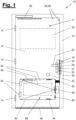
- a closing body is designated with reference number (10).
- the closing body (10) is formed by a door (11).
- the example of the door (11) represents the design most commonly expected in practice and is also representative of the other possible embodiments of the closing body (10), in particular a window or a flap.
- the invention is explained below using the example of the door (11).
- the person skilled in the art knows that the components intended for a door, such as locking fittings, door locks, hinges, door frames, etc., can be present in a corresponding manner in windows and flaps and other pivoting locking bodies, for example as a window lock, hinge and window frame or as a flap lock, hinge and flap frame.
- the terms used for the example of the door (11) also stand for functionally equivalent components of a window and a flap.
- the door (11) comprises a door leaf (12) which is pivotably attached to a door frame (16) via hinges (14).
- door leaf thus refers to any movable main part of the closing body (10) which opens or closes the access opening to the space which is pressurized.
- the door leaf (12) can close the door frame (16) in a form-fitting manner, so that when closed, no air or smoke (8) can pass through this door (11).
- the door frame (16) is anchored in a passage in a brickwork (not shown here).
- a locking fitting (18) contains in the example of Figure 1 a door lock (20) with an actuating latch (22).
- the actuating latch (22) can have any physical design. In the form shown, it can be designed as a rotating handle (door handle, window handle, etc.). Alternatively or additionally, it can be designed as a panic bar, as a push bar or as a rotary knob.
- the actuating latch (22) can comprise an actuator or be connected to an actuator, wherein the actuator is activated by a control means.
- the control means can be of any type, for example a door opening switch arranged on the door or near the door, or a building control system.
- the door lock (20) is preferably a panic lock (24) which can be opened at any time from one side, usually from the inside of a usable area (3) of a building (1).
- the panic lock (24) can be locked from the other side, although this is optional.
- the fact that it can be opened from one side ensures that the access opening or the passage to the escape route room can be opened from one side at any time by operating the locking body, even if the panic lock (24) cannot be opened from the other side. This ensures an escape route through the door (11) to the outside at all times.
- a panic lock (24) can be opened from always open from exactly one side of the locking body (10) in order to clear an escape route, in particular an escape route into the stairwell (2a) of a building (1). From the other side of the locking body (10), the opening can be temporarily released and temporarily blocked.
- the door (11) is closed automatically with a spring-elastic pre-tensioned door closer (26).
- the door closer (26) is preferably attached to the closing body (10) or integrated into the closing body (10).
- the door closer (26) can be attached to the door frame (16).
- the door closer (26) can be integrated into a hinge (14) of the closing body (10).
- the term "spring-elastic” includes any energy storage technology approved for closing doors (e.g. closing windows or flaps) on escape routes, for example mechanical springs, gas springs or systems for storing potential energy.
- valve device In the lower area of the door leaf (12) there is a mechanical valve device (28).
- an opening (30) is provided in the door leaf (12), which is opened or closed with the valve device (28).
- the valve device (28) comprises a valve flap (32) which is pivotably arranged on the door leaf (12) with hinge bands (34).
- hinge straps (34) are on the outside of the door leaf (11) and the valve flap (32)
- the hinge bands (34) can be integrated into the valve flap (32) or into the opening gap between the valve flap (32) and the opening (30), which is exemplified in Figures 11A and 11B is shown.
- a spring-loaded flap closer (36) preferably automatically closes the opening (30) with the valve flap (32).
- the flap closer (36) can have the same or a different design as the door closer (26). It can preferably be integrated into the valve flap (32) or the opening gap between the valve flap (32) and the opening (30) in the door leaf (11). Alternatively, the flap closer (36) can be integrated into the closing body (10) (cf. Figures 5A to 6C ). Alternatively, the flap closer (36) can be integrated into a hinge band (34) with which the valve flap (32) is pivotally mounted on the closing body (10).
- a second latch preferably designed in the form of a panic latch lock (38), secures the valve flap (32).
- the safety mechanism preferably acts in one direction, so that the valve flap (32) only opens to one side.
- the opening direction (V) of the valve flap (32) is shown in the figures in various designs, in particular in Figures 3 to 7 .
- a panic latch lock (38) preferably comprises a lock case (63) on or in which the second latch and possibly a movement gear (not shown).
- the lock case can be inserted into a corresponding case holder (54, 55).
- the door lock (20), in particular the panic lock (24), can also comprise a lock case (19) and can be inserted into a case receptacle of the door leaf (54, 55).
- the door lock (2) in particular the panic lock (24), and the panic latch lock (38) are preferably mechanically coupled to one another via a coupling mechanism (40). They can be opened simultaneously or with a slight delay to one another using a release mechanism (42).
- the valve flap (32) preferably opens first in order to equalize the pressure.
- the coupling for the activation can be designed not mechanically, but for example electrically, hydraulically or pneumatically.
- the release mechanism (42) can also receive a signal from a pressure sensor (43), which controls the release mechanism (42) in a suitable manner for opening and closing.
- An opening limiter (44) preferably only allows a defined opening range of the valve flap (32). In this way, it can be prevented that the valve flap (32) opens too far and, for example, injures a person standing in front of the door or causes other Damage.
- the opening limiter (44) can alternatively or additionally cause a damping of the opening movement of the valve flap (32). The damping can possibly be provided exclusively in the opening direction, but not in the closing direction of the valve flap (32).
- the opening limiter (44) can have any design. It can be designed according to the example in Figures 1 and 5A to 6C can be designed as a mechanical stop and can be arranged, for example, in the gap between the valve flap (32) and the opening (30). Alternatively or additionally, the opening limiter (44) can be integrated into another element, for example in the flap closer (36) or a hinge band (34).
- a locking mechanism (46) allows the valve flap (32) to lock into place so that it does not move accidentally.
- the locking mechanism can be designed as desired.
- the locking mechanism (46) can be a component of the release mechanism (42) and in particular can cause or contribute to the valve device (28) opening or closing as required, i.e. in particular only when there is a sufficiently high pressure difference.
- a retractable sealing rail (48) seals the door (11) so that no smoke (8) can penetrate through the gap between the floor and the door leaf (12).
- the closing body (10) and the valve device (28) can have various other seals (58).
- the closing body (10) has a fold (56), in particular a door fold, which overlaps the frame (16) in the closed state.
- the valve flap (32) has a fold (57), in particular a flap fold, which overlaps the inner contour of the opening (30) in the closed state.
- In the area of the overlap of the at least A seal (58) is preferably arranged in a fold (56, 57) (cf. Figures 1 , 8 and 11 .
- FIG. 2 shows an example representation of a building (1).
- the building (1) has several rooms (2), the access openings or passages of which can be opened or closed by means of a closing body (10) according to the present disclosure.
- a closing body (10) according to the present disclosure.
- the building has a smoke pressure system (5).
- This is designed to constantly supply fresh air into the stairwell (2, 2a) so that an overpressure (P+) is created there.
- P+ overpressure
- the pressure level in the stairwell (2a) should still be higher than the external atmospheric pressure (Pa).
- the lock (2b) could also be placed under overpressure.
- the building (1) according to Figure 2 comprises a controllable smoke and heat extractor (6) in the upper area of the stairwell (2a).
- This can be a controllable flap whose opening cross-section can be regulated so that the smoke (8) introduced can escape there, but on the other hand the overpressure (P+) in the stairwell (2a) is maintained at a certain level.
- all locking bodies (10) that are attached to access openings or passages to the pressurized room (2) are generally closed. This is done in particular by the door closers (26), which may also be controlled for this purpose.
- the locking fittings (18) of the locking bodies (10) can be designed to be controllable, for example to retract the bolts (23) of the door locks (20) - if any.
- the first latches (21) of the door locks (20) usually remain in the extended position, but may be switched softly so that the closing bodies (10) can be opened and closed again.
- the closing bodies (10) which close access openings or passages to the pressurizable space (2) include, in the example of Figure 2 all the doors shown on the upper floors that adjoin the staircase (2a) and the lock (2b), as well as the door on the ground floor that leads to the foyer (4). Furthermore, one or more windows or flaps can be present that are designed as closing bodies (10) according to the present disclosure. In the example of the Figure 2 A representative window is shown that can provide an exit to the roof above the foyer (4).
- the locking bodies (10) are generally installed in such a way that they open in the assumed escape direction. This means that the door opening direction (R) is generally identical to the escape direction.
- the term "door opening direction” analogously covers the opening direction of a window or flap.
- the opening direction (V) of a valve flap (32) can be in the same direction or opposite to the door opening direction (R), which can lead to different functions and advantages based on the following examples.
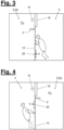
- Figure 3 explains an example that can occur at the door of the lowest usable area (3). It is assumed that a person is in the usable area (3) and wants to escape to the stairwell (2a) through the passage that is closed by the locking body (10), here a door (11). In this case opens the door in the opening direction (R) towards the stairwell (2a), where the overpressure (P+) prevails. In the usable area (3) the significantly lower normal pressure (P-) prevails. In other words, there is a pressure difference above the closed locking body (10), which results in a pressure difference force (F) that acts against the direction of door opening (R) and thus also against the escape direction.
- This pressure difference force (F) can, for example, have the standard level of around 100 Newtons. However, it can also be significantly higher and amount to 1000 Newtons, 2000 Newtons or even more.
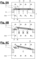
- FIG 5A it is shown how the second latch or panic latch lock (38) opens as a result of the movement of the actuating latch (22) and the actuating coupling. This releases the valve flap (32).
- the opening direction (V) of the valve flap (32) is in the opposite direction to the door opening direction (R).
- the pressure difference force (F) therefore acts in the valve flap opening direction (V) and will continue to be present until the valve cap (32) is released.
- the pressure difference force (F) presses the valve flap (32) with great force from the moment of release in the direction of the lower pressure level, in this case the normal pressure (P-). A very rapid opening movement of the valve flap (32) occurs.
- valve flap (32) If there is a locking mechanism (46) on the valve flap (32) (in Figure 5A not shown), for example a spring-loaded locking lug, the locking force (G') of the locking mechanism (46) is overcome. If a flap closer (36) is provided on the valve flap (32), the valve flap (32) is opened against the closing force (S) of the flap closer (36), the flap closer being elastically tensioned.
- a locking mechanism (46) on the valve flap (32) for example a spring-loaded locking lug
- An opening limiter (44) is preferably provided which allows a certain opening width of the valve flap (32) up to a threshold value, but not beyond that.
- the threshold value can be in the range of a few centimeters and in particular less than 10 cm, more particularly less than 7 cm.
- Figure 5B explains the condition that occurs when the valve flap (32) is opened. At least in a local area on both sides in front of and behind the closing body (32) a pressure equalization occurs, represented by the symbol (P-) for the normal pressure on both sides of the closing body (10) in front of and behind the opening zone of the valve device (24).
- the closing body (10) can open unhindered. Since the pressure difference force (F) is no longer effective or is barely effective, the flap closer (36) can move the valve flap (32) back into the closed position. The valve flap is secured in the closed position by the second latch or the panic trap lock (38). After the fleeing person has left, the door closer also moves the closing body (10) back into the closed position in order to separate the pressurized room (2), here the stairwell (2a), from the usable area (3) as gas-tight as possible.
- Figure 4 explains another case, for example, at the door on the ground floor of the house according to Figure 2 can occur.
- the pressure difference across the closing body (10) is in the opposite direction to the situation after Figure 3 before.
- the person attempting to enter may not know anything about the pressure difference force, especially if they are a civilian attempting to rescue someone, because the pressure difference force (F) is not visible.
- the person will activate the actuating latch (22) of the locking body (10) and attempt to open the door.
- the pressure difference force (F) now acts in the same direction as the door opening direction. (R) and thus presses the door out of the frame (16). Due to the innovation according to the present disclosure, the person is not injured when opening the locking body (10).
- Figures 6A to 6C explain the further processes that can be expected.
- FIG 6A it is shown how, as a result of the movement of the actuating latch (22) and the actuating coupling, the second latch or panic latch lock (38) opens again, in this case earlier than the first latch (21). This releases (initially only) the valve flap (32).
- the opening direction (V) of the valve flap (32) is now in the same direction as the door opening direction (R), ie the opposite is true of Figure 5A
- the pressure difference force (F) again acts in the valve flap opening direction (V) and will also continue to be present until the valve cap (32) is released.
- the pressure difference force (F) will press the valve flap (32) open with great force from the moment of release in the direction of the lower pressure level, in this case the normal pressure (P-).
- valve flap (32) is closed against the Closing force (S) of the flap closer (36) opens, whereby the flap closer is elastically tensioned.
- a locking mechanism (46) on the valve flap (32) for example a spring-loaded locking lug
- the locking force (G ⁇ ) of the locking mechanism (46) is overcome.
- a flap closer (36) is provided on the valve flap (32)
- the valve flap (32) is closed against the Closing force (S) of the flap closer (36) opens, whereby the flap closer is elastically tensioned.
- An opening limiter (44) is preferably provided which allows a certain opening width of the valve flap (32) up to a threshold value, but not beyond that.
- the threshold value can be in the range of a few centimeters.
- Figure 6B explains the situation that occurs when the valve flap (32) is opened.
- pressure equalization occurs at least in a local area on both sides in front of and behind the closing body (32).
- the stairwell (2a) and the foyer (4) for example because the smoke pressure system continues to supply air.
- the amount of the pressure difference drops massively in this example, so that the pressure difference force (F) is almost canceled out. This effect occurs again within fractions of a second.
- the first latch (21) opens, so that the locking body (10) is completely unlocked and can be opened normally.
- the person entering the door does not notice that just a fraction of a second earlier, the door was subjected to a force of, for example, 1000 Newtons or more in the opening direction.
- the intruder can be controlled according to the transition from Figure 6B to Figure 6C open the locking body (10) without it hitting you. Since the pressure difference force (F) is no longer effective or only works to a very small extent, the flap closer (36) can move the valve flap (32) back into the closed position in this example. The valve flap (32) is secured in the closed position by the second latch or the panic latch lock (38). After the intruder has left, the door closer (26) moves the locking body (10) back into the closed position in order to separate the pressurized room (2), here the stairwell (2a), from the usable area (3) as gas-tight as possible.
- first valve flap (32) in a first height section of the closing body (10) and a second valve flap (32) in a second height section.
- the first valve flap (32) can thus be provided in the upper or lower half of the closing body and the second valve flap (32) in the other half.
- valve flap (32) By limiting the opening width of the valve flap (32), the risk of injury is significantly reduced.
- the height of the arrangement of a valve flap (32) can provide additional advantages and further reduce the risk of collision.
- a valve flap the opening direction (V) of which is in the same direction as the door opening direction (R) can advantageously be arranged in an upper section of the closing body (10), which is to be expected in particular at chest height of the fleeing person. This is because a person who wants to open a door by pulling is usually further away from the door leaf with the upper part of his body than with the lower part of his body (cf. pose in Figure 4 ). An arrangement in the upper section thus promises a lower risk of collision.
- a valve flap, the opening direction (V) of which is opposite to the door opening direction (R), can advantageously be arranged in a lower section of the closing body (10), which is to be expected in particular at a leg or knee height of the fleeing person. This is because a person who wants to open a door by pushing is usually further away from the door leaf with the lower part of his body than with the upper part of his body (cf. pose in Figure 3 ).
- the door (11) can be seen in the example of Figure 1 only open outwards - away from the pressurised room - so that the escape route can be cleared quickly. If a person enters the pressurised room from outside and opens the door (11), the door (11) would slam against them due to the pressure and under certain circumstances even injure the person. Therefore, the valve flap (32) of the valve device (28) opens first to equalise the pressure. Only then can the door (11) be opened essentially pressure-free. For this purpose, the valve flap (32) is mechanically connected to the panic lock (24) via the coupling mechanism (40). The release mechanism (42) releases the valve device (28) and then the door (11).
- Figure 9 illustrates in a diagram the progression of a pressure difference force (F) in the opening direction of the Valve flap (32) and the opposing closing forces (G, G ⁇ , S) for the example of Figures 4 and 6A to 6C over time. Below the diagram, the opening and closing states of the closing body (10) and the valve flap (32) are illustrated.
- the closing body and valve flap (32) are closed.
- the full pressure difference force (F) is applied across the valve flap (32).
- the valve flap (32) is held in the closed position by the second latch (38).
- the second latch (38) applies a reaction force as closing force (G) that is the same amount as the pressure difference force (F).
- Part of the closing force (G) may also be generated by a permanent preload of the flap closer (26).
- the pressure difference force (F) acts on the valve flap (32) to an ever decreasing extent, approximately with the cosine component of the door opening angle.
- States Z4 and Z5 illustrate the closing movement of the closing body (10) caused by the door closer (26).
- the closing body (10) is once again in the closed position.
- the various seals (48, 58) preferably ensure a substantial volume separation between the interior and the exterior.
- a dynamic pressure can build up again. The temporary pressure equalization is thus terminated.
- Figure 10 shows an alternative force curve analogous to Figure 9 .
- the opening of the closing body (10) is initiated but only partially.
- Such a state could occur, for example, if a person determines during the movement of the actuating latch (22) that there is a dangerous situation behind the closing body (10) and then refrains from further opening of the closing body (10), while the valve flap (32) has already been released and pressure equalization has been initiated.
- the processes for the times t0 and t1 are identical to, for example, Figure 9 .
- valve flap (32) is opened to a certain extent, whereby the latching force (G ⁇ ) and the closing force (S) of the flap closer have been overcome for the opening path up to that point.
- the pressure difference force (F) drops to a lesser extent than in Figure 9 because the closing body (10) does not open additionally and a pressure-increasing effect may already be occurring due to the smoke pressure system.
- the sealing closure of the valve flap (32) could possibly be compromised, so that the protection against the passage of smoke at the access opening or the passage could be impaired or the re-achievement of the desired overpressure level in the escape room could be impaired. If such a disturbance were to occur only in one or a few closing bodies (10) of the building (1), the smoke pressure system (5) would probably be sufficient to achieve the desired effect despite the resulting leakage flow. Nevertheless, it would be advantageous to avoid such conditions with an undesirable residual opening of the valve flap.
- FIGS 11A and 11B explain an advantageous design of the closing body, with which an undesirable residual opening of the valve flap (32) can be eliminated.
- the closing body (10) preferably has an additional closing device (50) which is designed to open the valve flap (32) from an open position in which the opening width is greater than zero and smaller than a Residual opening threshold value is driven to move into the closed position.
- the additional locking device can have any suitable construction. For example, it can act mechanically and be designed as a movable and drivable lever, which is assumed to be representative below.
- the additional locking device (50) can act in any other way, in particular magnetically, electrically, hydraulically or pneumatically.
- the additional locking device (50) preferably has a movement device, the movement device being designed such that the additional locking device (50) can be actuated from a waiting position ( Figure 11A ), in which the additional closing device is not in engagement with the valve flap (32), is moved into a closing position (11B) while taking the valve flap (32) with it.
- the movement device can have any design. In the example of Figure 11 it can be a bistable transmission.
- the movement device can further be designed in such a way that the additional closing device (50) is automatically moved back to the waiting position after reaching the closing position. In this way, it is ensured that the additional closing device does not hinder an opening movement of the valve flap (32), i.e. no additional force (G) in the closing direction. In other words, the additional closing device (50) acts exclusively in a driven manner in the closing direction of the valve flap (32).
- the additional locking device (50) has a triggering means to trigger a movement of the additional locking device (50) from the waiting position to the closed position.
- the triggering means can have any design. In the example of Figure 11 the triggering means is not shown. However, it could be designed, for example, as a mechanical switching means, in particular as a one-sided driver, which is activated when the valve flap (32) moves in the closing direction when the residual opening threshold value is reached.
- the triggering means is thus preferably designed such that it triggers the movement when the valve flap (32) is in a partially opened state in which the opening width is less than or equal to the residual opening threshold value.
- a particularly energy-efficient effect is achieved if the triggering means is designed to continue to trigger the movement only when the partially open state is reached at the end of an opening movement and/or when the partially open state exists for a period of time that is greater than a waiting time threshold value.
- the additional locking device is preferably connected to an energy storage device (52).
- this can be a mechanical energy storage device (52) which, for example, comprises a tensionable drive means.
- the energy storage device (52) can preferably be charged by a movement of the actuating latch (22), in particular by a multiple movement of the actuating latch. This ensures that the energy that is required for the remaining closure of the valve flap (32) is not drawn from a movement that is generated by the pressure difference force (F), but for example from the regular door operation outside of the fire situation.
- the energy storage device (52) can thus be pre-charged before the fire situation occurs.
- the energy storage device (52) can support a first actuation of the additional locking device (50) in the fully charged state and at least one further actuation of the additional locking device (50) without an intermediate charging process.
- a particularly safe design is achieved if the energy storage device (52) in the fully When charged, it supports at least five or more consecutive operations without intermediate charging.
- Figure 12 shows an example of a door leaf (12) and a locking fitting set (60) which can be used individually or together to form a locking body according to the present disclosure.
- the locking fitting set (60) can also be used with another door leaf, for example an existing door on which an opening (30) is made separately.
- the door leaf (12) can also be combined with other locking means in order to achieve the claimed function of the locking body (10) according to the present innovation.
- the locking fitting set (60) shown in Figure 12 However, the devices shown have particular advantages and enable a modular construction of closing bodies (10) for different application situations.
- the locking fitting set is intended for attachment to a door leaf (12) of a pivotable door (11) or a pivotable window or a pivotable flap. It is further intended for forming a locking body (10) according to the present disclosure.
- the locking fitting set (60) comprises a locking fitting (18) for mounting on the door leaf (12) and further a push rod (39 ⁇ ) which corresponds to a retraction movement of a first Latch (21) of the locking fitting (18) is moved, and/or is moved corresponding to a movement of the actuating pawl (22) or the pawl receptacle (42) of the locking fitting (18).
- the locking fitting set (60) comprises an additional latch, which is designed as a panic latch lock (38) with a lock case (19) and a thrust body (39), and a coupling mechanism (40) for connecting the thrust body (39) to the push rod (39').
- an additional latch which is designed as a panic latch lock (38) with a lock case (19) and a thrust body (39), and a coupling mechanism (40) for connecting the thrust body (39) to the push rod (39').
- push rod and “push body” refer to structural means whose function is familiar to those skilled in the art. They include translationally movable devices for transmitting forces that are rigid in at least one loading direction, for example rods, rails, bolts, ropes, chains and the like. However, they also include partially or completely rotationally movable devices.
- the locking fitting set additionally comprises a valve device (28) which is designed as a valve flap (32) and can be inserted into an opening (30) of the door leaf.
- a release mechanism (42) is formed by the connection of the push body (39) and the push rod (39'), which is coupled to the locking fitting (18) and opens the valve device (28) so that the Valve device (28) causes a temporary pressure equalization when the door leaf is opened if there is a pressure difference between the inside and the outside of the existing door.
- valve flap (32) is not shown for reasons of simplification. It can have any suitable design, for example as shown in Figures 1 and 3 until 8 and 11.
- the valve flap (32) can preferably be pivotally connected to the closing body (10) via one or more pivoting devices, in particular hinge bands (34).
- the pivoting devices can be separate or can be a component of the door leaf (12) or the locking fitting set (60).
- the at least one pivoting device is preferably arranged on an outer side of the closing body (10) and the valve flap (32) in the intended assembly state (cf. Figure 1 ). Alternatively, it can be arranged concealed in a gap between the valve flap (32) and the edge of the opening (30) (cf. Figure 11 ).
- the locking fitting set (60) comprises the second latch, which in the intended assembly state is arranged on the edge of the opening (30) and secures the valve flap (32) in the closed position.
- Particularly preferred The locking fitting set (60) includes a panic latch lock (38) which is designed as a mortise lock with a lock case (63). This enables a modular construction and facilitates the installation of the second latch on the door leaf (32).
- the locking fitting set (60) can further comprise at least one further panic latch lock (38) and/or at least one further deadbolt lock, which is/are coupled to the locking fitting (18) in an actuating manner in the intended assembly state.
- the door leaf according to the preferred design in Figure (12 ) is the door leaf of a pivoting door (11), a pivoting window or a pivoting flap.
- the term "door leaf” is therefore representative of the movable main part of a closing body (10) to be formed, which opens or closes the access opening to the space that is pressurized.
- the door leaf (12) has at least one opening (30) to which a valve flap can be attached or is attached.
- the door leaf (12) has at least one box receptacle (54) on an outer edge and a push rod channel (61) adjoining the box receptacle (54).
- the door lock (20) can preferably be inserted into the box holder (54).
- the push rod (39') can preferably be accommodated in the push rod channel (61).
- the push rod channel (61) is preferably covered by a faceplate (25) in the intended assembly state.
- the door leaf (12) further comprises, at an edge portion of the opening (30), a further box receptacle (55) which is designed to receive a lock case (63) of a panic latch lock (38), and a sliding body channel (62) which adjoins the further box receptacle (55) and extends in the direction of the first box receptacle (54).
- the thrust body (39) of the panic latch lock (38) is accommodated and possibly guided in the thrust body channel (62).
- the door leaf can further have a connecting cavity (64) in an area between the push rod channel (61) and the thrust body channel (62).
- Another part of the coupling mechanism (40) can be accommodated and possibly guided in this connecting cavity, in particular a bridge or a spacer, via which the thrust body (39) and the push rod (39') are connected to one another in an actuating manner in the intended assembly state.
- the further part of the coupling mechanism (40) is designed, for example, as a coupling rod, which here has a parallelogram shape.
- the coupling rod can be connected in any way to the push rod (39') on the one hand and to the push body (39) on the other hand, for example by welding, gluing, screwing or riveting.
- the coupling rod can also be used as a single rod, as a flat body (cf. Figure 1 ), or as multiple rods with a different shape.
- Further components of the coupling mechanism (40) may include force deflections, gears, cable pulls or chain pulls.
- All described components of the locking fitting set (60) and the door leaf (12) according to Figure 12 can also be a component of the locking body (10) individually or in any combination.
- all means attached to the door leaf (12) that contribute to the locking function can be a component of the locking fitting set (60), i.e. in particular the door closer (26), the flap closer (36), the opening limiter (44), the additional locking device (50), the energy storage device 52, the locking mechanism (46) and the hinge bands (14, 34).
- the release mechanism (42), in particular the panic latch lock (38), can preferably comprise at least one sliding body (39) which can be coupled or is coupled to the locking fitting (18) in an actuating manner.
- the coupling can be carried out in any manner.
- a separate gear can be provided. (not shown) which is connected to the actuating pawl (22) or a pawl receptacle (41) of the locking fitting (18) and transmits a movement of the actuating pawl (22) or the pawl receptacle (41) to the sliding body (39).
- the locking fitting (18) can alternatively or additionally have a push rod (39').
- the gear can be connected to a push rod (39') of the locking fitting (18) and transmit a movement of the push rod (39') triggered on the basis of the movement of the actuating pawl to the push body (39).
- the push rod (39') can in particular be moved corresponding to a retraction movement of the first latch (21). It can alternatively or additionally be moved corresponding to a movement of the actuating pawl (22) or the pawl receptacle (42).
- the sliding body (39) moves when the actuating latch (22) moves, and thus the second latch (38) is also moved.
- the coupled movements can take place at the same speed or at different speeds.
- a retraction movement of the second latch can be slightly accelerated compared to a retraction movement of the first latch.
- any other design of the release mechanism (42) or the coupling device (40) is possible in order to achieve the above-mentioned effect.
- the ratio of the surfaces of the closing body (10), in particular the door leaf (12), and the valve flap (32) can be chosen arbitrarily.
- a valve flap (32) has a size that corresponds to at least 5-10% of the surface of the closing body (10), in particular the door leaf (12).
- the size of the valve flap (32) can more preferably be 20% to 40% of the surface of the closing body (10).
- valve flaps (32) Two or more valve flaps (32) can be provided. If several valve flaps (32) have a matching opening direction (V), the above recommendation for the area ratio refers to the total surface area of these several valve flaps (32).
- the valve flap (32) can have any position, any format and any angular orientation.
- the hinge band side of the valve flap (32) can be provided at any angle on the closing body (10).
- the hinge band side can be located at the upper edge of the opening (30), at the lower edge of the opening (30) or at a lateral edge of the opening (30).
- the hinge band side is provided on a lateral edge of the opening (30), in particular on the edge of the opening (30) which is remote from the locking fitting (18).
- the second latch (38), in particular the panic latch lock, can be provided on any edge of the opening (30).
- the panic latch lock is preferably provided opposite the hinge band side.
- a second latch, in particular a panic latch lock can be provided on a side that is substantially transverse to the hinge band side.
- the locking body (10) can comprise at least one further panic latch lock (49) and/or at least one further deadbolt lock (not shown), which is/are coupled to the locking fitting (18) for actuation purposes (cf. Figure 12 below).
- the additional panic lock (38) and/or deadbolt lock can be part of the locking fitting set.
- the further panic latch lock (49) can be connected to the door lock (20) via the push body (39) in an actuating manner.
- the further deadbolt lock can be connected to the door lock (20) via a further mechanism.
- the faceplate (25) can rigidly connect the door lock to the at least one further panic latch lock (49) and/or at least one further deadbolt lock in order to ensure force support for the push body (39) and/or the further mechanism and/or the push rod (39').
- the locking body (10) can have a first valve flap (32) and at least one further valve flap (32).
- the further valve flap (32) can be arranged separately in a further opening in the door leaf (12). Alternatively, it can be arranged as a cascaded valve flap (32) in an opening which is arranged in the first valve flap (32) (cf. dashed illustration below in Figure 1 ).
Landscapes
- Engineering & Computer Science (AREA)
- Structural Engineering (AREA)
- Civil Engineering (AREA)
- Architecture (AREA)
- Health & Medical Sciences (AREA)
- General Health & Medical Sciences (AREA)
- Business, Economics & Management (AREA)
- Emergency Management (AREA)
- Special Wing (AREA)
Claims (26)
- Gâche pour fermer et ouvrir une ouverture d'accès ou un passage d'une pièce, avec une différence de pression entre l'intérieur et l'extérieur de la pièce, la gâche (10) étant conçue comme une porte pivotante (11), une fenêtre pivotante ou un volet pivotant, caractérisé en ce qu'- un dispositif de soupape (28) est prévu sur la gâche (10), ce qui provoque une compensation temporaire de la pression lors de l'ouverture de la gâche (10), et- dans lequel le dispositif de soupape (28) est conçu comme un clapet de soupape
(32) et un mécanisme de déclenchement (42) est prévu pour ouvrir le dispositif de soupape (28), et- une ferrure de verrouillage (18) est prévue pour la gâche (10), et le mécanisme de déclenchement (42) est couplé à la ferrure de verrouillage (18) de la gâche (10) de manière à pouvoir être actionné,- le mécanisme de déclenchement (42) est un mécanisme de déclenchement mécanique, électronique, pneumatique et/ou hydraulique (42), dans lequel- un capteur de pression (43) est prévu, qui commande le mécanisme de déclenchement (42). - Gâche selon la revendication précédente,
dans laquelle le mécanisme de déclenchement (42) ne fait que déclencher une ouverture du dispositif de soupape (28) et dans laquelle le mouvement d'ouverture du dispositif de soupape (28) est provoqué par une force de différence de pression (F) résultant de la différence de pression entre l'intérieur et l'extérieur. - Gâche selon l'une quelconque des revendications précédentes, dans laquelle la ferrure de verrouillage (18) est une ferrure de verrouillage mécanique, électronique, pneumatique et/ou hydraulique (18).
- Gâche selon l'une quelconque des revendications précédentes, dans laquelle la ferrure de verrouillage (18) contient une serrure de porte (20) avec un cliquet d'actionnement (22).
- Gâche selon l'une quelconque des revendications précédentes, dans laquelle la gâche comprend un premier pêne (21) maintenant la gâche à l'état fermé par rapport à un cadre et un second pêne (38) maintenant le dispositif de soupape (28), notamment le clapet de soupape (32) à l'état fermé par rapport à la gâche (10).
- Gâche selon la revendication 4, dans laquelle la serrure de porte (20) est une serrure anti-panique (24) qui peut être ouverte à tout moment d'un côté pour dégager une issue de secours.
- Gâche selon la revendication 5 précédente,
le premier pêne (21) faisant partie intégrante de la serrure de porte (20) et notamment de la serrure anti-panique (24). - Gâche selon la revendication 5 précédente,
dans laquelle le deuxième pêne (38) est conçu sous la forme d'une serrure anti-panique à pêne dormant qui bloque le clapet de soupape (32). - Gâche selon l'une quelconque des
revendications précédentes, dans laquelle le mécanisme de déclenchement (42) comprend un moyen de commande qui ouvre le dispositif de soupape (28) en amont de la gâche (10). - Gâche selon l'une quelconque des revendications précédentes, dans laquelle le mécanisme de déclenchement (42) comprend au moins un corps de poussée (39) couplé à la ferrure de verrouillage de manière à pouvoir être actionné.
- Gâche selon la revendication précédente,
dans laquelle le corps de poussée (39) est relié à une tige de poussée (39') qui- est déplacée en correspondance avec un mouvement de rétraction du premier pêne (21), et/ou- est déplacée en correspondance avec un mouvement du cliquet d'actionnement (22) ou du logement du cliquet (42).) - Gâche selon l'une quelconque des revendications précédentes 5, 7 ou 8, dans laquelle le deuxième pêne (38) a une longueur de languette (U2) plus courte que la longueur de languette (Ul) du premier pêne (21).
- Gâche selon l'une quelconque des revendications précédentes, dans laquelle la gâche (10) présente un dispositif de fermeture supplémentaire conçu pour déplacer le clapet de soupape (32) d'une position ouverte, dans laquelle la largeur d'ouverture est supérieure à zéro et inférieure à un seuil d'ouverture résiduel, vers la position fermée.
- Gâche selon la revendication 13, dans laquelle le dispositif de fermeture supplémentaire est relié à un accumulateur d'énergie (52), en particulier à un accumulateur d'énergie mécanique.
- Gâche selon la revendication 14 précédente, dans laquelle l'accumulateur d'énergie (52) est chargé par un mouvement du cliquet d'actionnement (22), en particulier par un mouvement multiple du cliquet d'actionnement.
- Gâche selon l'une des revendications précédentes 14 ou 15, dans laquelle l'accumulateur d'énergie (52) prend en charge, à l'état complètement chargé, un premier actionnement du dispositif de fermeture supplémentaire et, sans opération de charge intermédiaire, au moins un autre actionnement du dispositif de fermeture supplémentaire, de préférence au moins cinq actionnements consécutifs sans opérations de charge intermédiaires.
- Gâche selon l'une quelconque des revendications précédentes 13 à 16, dans laquelle le dispositif de fermeture supplémentaire (50) présente un dispositif de mouvement, en particulier un engrenage bistable, le dispositif de mouvement étant conçu de telle sorte que le dispositif de fermeture supplémentaire (50) puisse être actionné- d'une position d'attente dans laquelle le dispositif de fermeture supplémentaire se trouve sans engagement avec le clapet de soupape (32),- à une position de fermeture en entraînant le clapet de soupape (32).
- Gâche selon la revendication 17 précédente, dans laquelle le dispositif de déplacement est en outre conçu de telle sorte que le dispositif de fermeture supplémentaire (50) est automatiquement ramené à la position d'attente après avoir atteint la position de fermeture.
- Gâche selon l'une quelconque des revendications précédentes 17 ou 18, dans laquelle le dispositif de fermeture supplémentaire (50) présente un moyen de déclenchement pour déclencher un mouvement du dispositif de fermeture supplémentaire (50) de la position d'attente à la position de fermeture.
- Gâche selon la revendication précédente,
dans laquelle le déclencheur déclenche le mouvement lorsque- le clapet de soupape (32) se trouve dans un état partiellement ouvert dans lequel la largeur d'ouverture est inférieure ou égale à la valeur seuil d'ouverture restante. - Gâche selon la revendication précédente,
dans laquelle le déclencheur ne continue de déclencher le mouvement que si- l'état partiellement ouvert est atteint à la fin d'un mouvement d'ouverture et/ou si- l'état partiellement ouvert est présent pendant une durée supérieure à un seuil de temps d'attente. - Gâche selon l'une quelconque des revendications précédentes, dans laquelle le clapet de soupape (32) est relié de manière pivotante à la gâche (10) par un ou plusieurs dispositifs de pivotement, en particulier des charnières plates (34).
- Gâche selon la revendication précédente,
dans laquelle le au moins un dispositif de pivotement- est disposé sur une face extérieure de la gâche (10) et
le clapet de soupape (32) est disposé ; ou- est caché dans un espace entre le clapet de soupape (32) et le bord de l'ouverture (30). - Gâche selon l'une quelconque des revendications précédentes, dans laquelle la gâche présente un autre clapet de soupape (32).
- Kit de ferrures de fermeture à monter sur un vantail de porte (12) d'une porte pivotante (11) ou d'une fenêtre pivotante ou d'un clapet pivotant, et pour former une gâche (10) selon la revendication 1, le kit de ferrures de fermeture comprenant une ferrure de verrouillage (18) à monter sur le vantail de porte (12), caractérisé en ce que le kit de ferrures de fermeture (60) comprend en outre :- une tige de poussée (39') déplacée en correspondance avec un mouvement de rétraction d'un premier pêne (21) de la ferrure de verrouillage (18) et/ou en correspondance avec un mouvement du cliquet d'actionnement (22) ou du logement de cliquet (42) de la ferrure de verrouillage (18) ; et- un piège supplémentaire conçu comme une serrure anti-panique à pêne dormant (38) avec un boîtier de serrure (19) et un corps de poussée (39) ; et- un mécanisme d'accouplement (40) pour relier le corps de poussée (39) à la tige de poussée (39') ; et- un dispositif de soupape (28) conçu comme un clapet de soupape (32) et pouvant être inséré dans une ouverture (30) du vantail de porte ;et dans lequel, dans le cadre du montage prévu, un mécanisme de déclenchement (42) est formé par la connexion du corps de poussée (39) et de la tige de poussée (39'), qui est couplé de manière opérationnelle à la ferrure de verrouillage (18) et ouvre le dispositif de soupape (28), de sorte que le dispositif de soupape (28) provoque une compensation temporaire de la pression lors de l'ouverture du vantail de porte, lorsqu'il existe une différence de pression entre l'intérieur et l'extérieur du vantail de porte.
- Vantail de porte d'une porte pivotante (11), d'une fenêtre pivotante ou d'un clapet pivotant, le vantail de porte présentant au moins une ouverture (30) sur laquelle un clapet de soupape peut être monté, le vantail de porte (12) présentant sur un bord extérieur au moins un logement de caisson (54) et un canal de tige de poussée (61) se raccordant au logement de caisson (54), caractérisé en ce que le vantail de porte (12) présente en outre :- sur une partie périphérique de l'ouverture (30), un autre logement de caisson (55) conçu pour recevoir un boîtier de serrure (63) d'une serrure anti-panique (38), et- un canal de corps de poussée qui se raccorde à l'autre logement de caisson (55) et qui s'étend en direction du premier logement de caisson (54),- dans lequel le vantail de porte (11) présente en outre une cavité de liaison dans une zone située entre le canal de la tige de poussée (61) et le canal du corps de poussée (62).
Applications Claiming Priority (2)
| Application Number | Priority Date | Filing Date | Title |
|---|---|---|---|
| DE202020106177.1U DE202020106177U1 (de) | 2020-10-28 | 2020-10-28 | Schließung mit Ventilvorrichtung |
| PCT/EP2021/079810 WO2022090307A1 (fr) | 2020-10-28 | 2021-10-27 | Fermeture dotée d'un dispositif de clapet |
Publications (3)
| Publication Number | Publication Date |
|---|---|
| EP4237649A1 EP4237649A1 (fr) | 2023-09-06 |
| EP4237649C0 EP4237649C0 (fr) | 2024-09-11 |
| EP4237649B1 true EP4237649B1 (fr) | 2024-09-11 |
Family
ID=73547446
Family Applications (1)
| Application Number | Title | Priority Date | Filing Date |
|---|---|---|---|
| EP21806991.2A Active EP4237649B1 (fr) | 2020-10-28 | 2021-10-27 | Fermeture dotée d'un dispositif de clapet |
Country Status (6)
| Country | Link |
|---|---|
| US (1) | US12421787B2 (fr) |
| EP (1) | EP4237649B1 (fr) |
| CN (1) | CN117083442A (fr) |
| DE (1) | DE202020106177U1 (fr) |
| PL (1) | PL4237649T3 (fr) |
| WO (1) | WO2022090307A1 (fr) |
Citations (4)
| Publication number | Priority date | Publication date | Assignee | Title |
|---|---|---|---|---|
| KR20040081724A (ko) * | 2004-08-30 | 2004-09-22 | 김길평 | 건축용 이중 도어 |
| EP2813660A1 (fr) * | 2012-02-10 | 2014-12-17 | Bx Tetsuya Co., Ltd. | Dispositif de portail doté d'un mécanisme de limitation de différence de pression |
| KR20190024759A (ko) * | 2017-08-30 | 2019-03-08 | 닛도오 고오기 가부시키가이샤 | 개폐 가능한 감압용 개구를 구비한 도어 및 감압용 패널 래치 장치 |
| CN109488179A (zh) * | 2018-12-27 | 2019-03-19 | 江苏兴顺消防门业有限公司 | 一种特殊的多功能消防门 |
Family Cites Families (28)
| Publication number | Priority date | Publication date | Assignee | Title |
|---|---|---|---|---|
| DE1148468B (de) | 1958-08-16 | 1963-05-09 | Kloeckner Humboldt Deutz Ag | Antriebsvorrichtung fuer zwei Tuerfluegel einer Schleuse fuer gasdicht abzuschliessende Raeume |
| US3314703A (en) * | 1965-03-01 | 1967-04-18 | Valley Metal Products Company | Panic release unit for windows and doors |
| US3345099A (en) * | 1965-09-14 | 1967-10-03 | Sargent & Greenleaf | Panic exit device |
| US3705739A (en) * | 1971-07-07 | 1972-12-12 | Ilco Corp | Panic lock device |
| US4050114A (en) | 1976-08-30 | 1977-09-27 | Eaton Corporation | Door closer assembly |
| US4210349A (en) * | 1978-12-26 | 1980-07-01 | Standard Keil Hardware Manufacturing Co. | Device for holding a door firmly closed |
| DE3912740C1 (en) * | 1989-04-19 | 1990-06-28 | Dictator Technik Dr. Wolfram Schneider & Co Verwaltungs- Und Beteiligungsgesellschaft, 8902 Neusaess, De | Safety fitting self-closing doors and windows - has hydraulic damping cylinder for door etc. closing mechanism, with locking member coupled to transfer element |
| JPH04102691A (ja) | 1990-08-21 | 1992-04-03 | Fujitsu Ltd | 気密室用ドア及び室圧差の緩和方法 |
| JPH07259407A (ja) * | 1994-03-16 | 1995-10-09 | Mitsui Constr Co Ltd | 防火扉装置 |
| DE19812319B4 (de) * | 1998-03-20 | 2009-09-24 | Sommer Metallbau-Stahlbau Gmbh & Co. Kg | Druckausgleichseinrichtung |
| US5927012A (en) * | 1998-06-22 | 1999-07-27 | The Bilco Company | Emergency release latch mechanism for smoke hatch |
| DE19937532A1 (de) | 1999-08-09 | 2001-02-15 | Brantec Gmbh Solothurn | Anordnung zur Einstellung einer Druckdifferenz |
| US6282929B1 (en) * | 2000-02-10 | 2001-09-04 | Sargent Manufacturing Company | Multipoint mortise lock |
| AU2003902273A0 (en) * | 2003-05-12 | 2003-05-29 | Freund, Carlos Alfredo | Barrier release system |
| DE202005007137U1 (de) | 2005-01-11 | 2005-09-22 | Reick, Michael, Dr.-Ing. | Mobile Rauch- und Brandschutzvorrichtung |
| EP2050908A1 (fr) * | 2007-10-16 | 2009-04-22 | Jeld Wen Türen GmbH | Mécanisme integré |
| WO2010040814A1 (fr) | 2008-10-08 | 2010-04-15 | Swiss Raltec Gmbh | Immeuble avec une cage d'escalier et un puits d'aération |
| JP5491739B2 (ja) * | 2009-01-29 | 2014-05-14 | 大成建設株式会社 | 扉用差圧調整機構 |
| AT515374B1 (de) * | 2014-02-05 | 2016-06-15 | Völkl Roland Dipl Ing | Türe, insbesondere Brandschutz- und Fluchttüre |
| EP3111024A4 (fr) * | 2014-02-26 | 2017-11-01 | Zhu, Sascha Shuxia | Élément de porte ou de fenêtre avec mécanisme d'équilibrage de la pression intégré |
| CN204266715U (zh) * | 2014-11-25 | 2015-04-15 | 徐州工程学院 | 一种机敏式泄爆栓 |
| CN106703649A (zh) * | 2017-01-24 | 2017-05-24 | 安徽通晓防火门有限公司 | 门中门 |
| JP7096088B2 (ja) * | 2017-08-30 | 2022-07-05 | 日東工器株式会社 | 開閉可能な減圧用開口を備えたドア及び減圧用パネルラッチ装置 |
| EP3536887A1 (fr) | 2018-03-05 | 2019-09-11 | Asivo OY | Procédé pour porte double en cas d'incendie et porte double |
| KR101904853B1 (ko) * | 2018-06-07 | 2018-10-10 | (주)진전기엔지니어링 | 건축물의 화재시 화염차단 기능을 갖춘 소방용 출입문 |
| KR101932620B1 (ko) * | 2018-08-20 | 2018-12-26 | 민규식 | 차압조절 기능을 갖는 방화문 |
| US11851925B2 (en) * | 2019-02-27 | 2023-12-26 | Sargent Manufacturing Company | Key override for electromechanical multi-point latching device |
| CN112431531A (zh) * | 2020-10-28 | 2021-03-02 | 浙江齐嘉消防科技有限公司 | 一种隧道式安全消防门 |
-
2020
- 2020-10-28 DE DE202020106177.1U patent/DE202020106177U1/de active Active
-
2021
- 2021-10-27 CN CN202180088247.1A patent/CN117083442A/zh active Pending
- 2021-10-27 WO PCT/EP2021/079810 patent/WO2022090307A1/fr not_active Ceased
- 2021-10-27 EP EP21806991.2A patent/EP4237649B1/fr active Active
- 2021-10-27 PL PL21806991.2T patent/PL4237649T3/pl unknown
- 2021-10-27 US US18/033,823 patent/US12421787B2/en active Active
Patent Citations (4)
| Publication number | Priority date | Publication date | Assignee | Title |
|---|---|---|---|---|
| KR20040081724A (ko) * | 2004-08-30 | 2004-09-22 | 김길평 | 건축용 이중 도어 |
| EP2813660A1 (fr) * | 2012-02-10 | 2014-12-17 | Bx Tetsuya Co., Ltd. | Dispositif de portail doté d'un mécanisme de limitation de différence de pression |
| KR20190024759A (ko) * | 2017-08-30 | 2019-03-08 | 닛도오 고오기 가부시키가이샤 | 개폐 가능한 감압용 개구를 구비한 도어 및 감압용 패널 래치 장치 |
| CN109488179A (zh) * | 2018-12-27 | 2019-03-19 | 江苏兴顺消防门业有限公司 | 一种特殊的多功能消防门 |
Also Published As
| Publication number | Publication date |
|---|---|
| DE202020106177U1 (de) | 2020-11-06 |
| US20230399887A1 (en) | 2023-12-14 |
| EP4237649A1 (fr) | 2023-09-06 |
| EP4237649C0 (fr) | 2024-09-11 |
| PL4237649T3 (pl) | 2025-02-10 |
| WO2022090307A1 (fr) | 2022-05-05 |
| US12421787B2 (en) | 2025-09-23 |
| CN117083442A (zh) | 2023-11-17 |
Similar Documents
| Publication | Publication Date | Title |
|---|---|---|
| EP0882169B1 (fr) | Porte coupe-feu | |
| EP3990344B1 (fr) | Dispositif pour empêcher l'accès à une zone d'un avion | |
| EP1250509B1 (fr) | Porte relevable par sections ou porte accordeon | |
| EP0356728A1 (fr) | Dispositif de commande de la séquence de fermeture de portes à doubles battants | |
| EP1029557A1 (fr) | Fermeture protectrice de fumée | |
| EP4341518B1 (fr) | Système de porte coulissante | |
| AT515374B1 (de) | Türe, insbesondere Brandschutz- und Fluchttüre | |
| EP1703066A2 (fr) | Porte coupe-feu et coupe-fumée | |
| WO2014086490A2 (fr) | Porte coulissante | |
| EP0858541B1 (fr) | Dispositif de verrouillage | |
| EP4237649B1 (fr) | Fermeture dotée d'un dispositif de clapet | |
| DE9409176U1 (de) | Rauchschutzeinrichtung für einen geschlossenen Treppenraum | |
| DE19917158C2 (de) | Mehrfachfunktions- und Sicherheitsrahmen für Fenster, Türen und sonstige bewegliche Flügel zum Verschließen von Öffnungen | |
| DE3737151C2 (de) | Verriegelungseinrichtung für eine zweiflügelige Tür | |
| EP2410113B1 (fr) | Verrouillage de protection anti-mines et procédé de déverrouillage du verrouillage de protection anti-mines | |
| DE10142083A1 (de) | Senkrecht-Schiebe-Fenster | |
| EP0769605A2 (fr) | Porte sectionnelle | |
| EP3822437A1 (fr) | Système de fenêtre ou de porte | |
| EP2851501A1 (fr) | Porte sectionnelle | |
| AT506155B1 (de) | Türe, insbesondere brandschutz- und fluchttüre | |
| EP1143386A1 (fr) | Dispositif de passage | |
| DE102005013743B4 (de) | Vorrichtung zum Freigeben eines Fluchtweges | |
| DE102020203078B4 (de) | Schiebetüranlage | |
| EP3587696B1 (fr) | Dispositif de fermeture d'espace pouvant être ouvert ainsi que son procédé d'ouverture | |
| DE102006012093A1 (de) | Feuer- und Rauchschutztür zum Verschließen von Türöffnungen |
Legal Events
| Date | Code | Title | Description |
|---|---|---|---|
| STAA | Information on the status of an ep patent application or granted ep patent |
Free format text: STATUS: UNKNOWN |
|
| STAA | Information on the status of an ep patent application or granted ep patent |
Free format text: STATUS: THE INTERNATIONAL PUBLICATION HAS BEEN MADE |
|
| PUAI | Public reference made under article 153(3) epc to a published international application that has entered the european phase |
Free format text: ORIGINAL CODE: 0009012 |
|
| STAA | Information on the status of an ep patent application or granted ep patent |
Free format text: STATUS: REQUEST FOR EXAMINATION WAS MADE |
|
| 17P | Request for examination filed |
Effective date: 20230526 |
|
| AK | Designated contracting states |
Kind code of ref document: A1 Designated state(s): AL AT BE BG CH CY CZ DE DK EE ES FI FR GB GR HR HU IE IS IT LI LT LU LV MC MK MT NL NO PL PT RO RS SE SI SK SM TR |
|
| DAV | Request for validation of the european patent (deleted) | ||
| DAX | Request for extension of the european patent (deleted) | ||
| GRAP | Despatch of communication of intention to grant a patent |
Free format text: ORIGINAL CODE: EPIDOSNIGR1 |
|
| STAA | Information on the status of an ep patent application or granted ep patent |
Free format text: STATUS: GRANT OF PATENT IS INTENDED |
|
| INTG | Intention to grant announced |
Effective date: 20240423 |
|
| GRAS | Grant fee paid |
Free format text: ORIGINAL CODE: EPIDOSNIGR3 |
|
| GRAA | (expected) grant |
Free format text: ORIGINAL CODE: 0009210 |
|
| STAA | Information on the status of an ep patent application or granted ep patent |
Free format text: STATUS: THE PATENT HAS BEEN GRANTED |
|
| AK | Designated contracting states |
Kind code of ref document: B1 Designated state(s): AL AT BE BG CH CY CZ DE DK EE ES FI FR GB GR HR HU IE IS IT LI LT LU LV MC MK MT NL NO PL PT RO RS SE SI SK SM TR |
|
| REG | Reference to a national code |
Ref country code: GB Ref legal event code: FG4D Free format text: NOT ENGLISH |
|
| REG | Reference to a national code |
Ref country code: CH Ref legal event code: EP |
|
| REG | Reference to a national code |
Ref country code: DE Ref legal event code: R096 Ref document number: 502021005149 Country of ref document: DE |
|
| REG | Reference to a national code |
Ref country code: IE Ref legal event code: FG4D Free format text: LANGUAGE OF EP DOCUMENT: GERMAN |
|
| U01 | Request for unitary effect filed |
Effective date: 20241009 |
|
| U07 | Unitary effect registered |
Designated state(s): AT BE BG DE DK EE FI FR IT LT LU LV MT NL PT RO SE SI Effective date: 20241029 |
|
| U20 | Renewal fee for the european patent with unitary effect paid |
Year of fee payment: 4 Effective date: 20241029 |
|
| PG25 | Lapsed in a contracting state [announced via postgrant information from national office to epo] |
Ref country code: NO Free format text: LAPSE BECAUSE OF FAILURE TO SUBMIT A TRANSLATION OF THE DESCRIPTION OR TO PAY THE FEE WITHIN THE PRESCRIBED TIME-LIMIT Effective date: 20241211 |
|
| PG25 | Lapsed in a contracting state [announced via postgrant information from national office to epo] |
Ref country code: GR Free format text: LAPSE BECAUSE OF FAILURE TO SUBMIT A TRANSLATION OF THE DESCRIPTION OR TO PAY THE FEE WITHIN THE PRESCRIBED TIME-LIMIT Effective date: 20241212 |
|
| PG25 | Lapsed in a contracting state [announced via postgrant information from national office to epo] |
Ref country code: HR Free format text: LAPSE BECAUSE OF FAILURE TO SUBMIT A TRANSLATION OF THE DESCRIPTION OR TO PAY THE FEE WITHIN THE PRESCRIBED TIME-LIMIT Effective date: 20240911 |
|
| PG25 | Lapsed in a contracting state [announced via postgrant information from national office to epo] |
Ref country code: RS Free format text: LAPSE BECAUSE OF FAILURE TO SUBMIT A TRANSLATION OF THE DESCRIPTION OR TO PAY THE FEE WITHIN THE PRESCRIBED TIME-LIMIT Effective date: 20241211 Ref country code: ES Free format text: LAPSE BECAUSE OF FAILURE TO SUBMIT A TRANSLATION OF THE DESCRIPTION OR TO PAY THE FEE WITHIN THE PRESCRIBED TIME-LIMIT Effective date: 20240911 |
|
| PG25 | Lapsed in a contracting state [announced via postgrant information from national office to epo] |
Ref country code: RS Free format text: LAPSE BECAUSE OF FAILURE TO SUBMIT A TRANSLATION OF THE DESCRIPTION OR TO PAY THE FEE WITHIN THE PRESCRIBED TIME-LIMIT Effective date: 20241211 Ref country code: NO Free format text: LAPSE BECAUSE OF FAILURE TO SUBMIT A TRANSLATION OF THE DESCRIPTION OR TO PAY THE FEE WITHIN THE PRESCRIBED TIME-LIMIT Effective date: 20241211 Ref country code: HR Free format text: LAPSE BECAUSE OF FAILURE TO SUBMIT A TRANSLATION OF THE DESCRIPTION OR TO PAY THE FEE WITHIN THE PRESCRIBED TIME-LIMIT Effective date: 20240911 Ref country code: GR Free format text: LAPSE BECAUSE OF FAILURE TO SUBMIT A TRANSLATION OF THE DESCRIPTION OR TO PAY THE FEE WITHIN THE PRESCRIBED TIME-LIMIT Effective date: 20241212 Ref country code: ES Free format text: LAPSE BECAUSE OF FAILURE TO SUBMIT A TRANSLATION OF THE DESCRIPTION OR TO PAY THE FEE WITHIN THE PRESCRIBED TIME-LIMIT Effective date: 20240911 |
|
| PG25 | Lapsed in a contracting state [announced via postgrant information from national office to epo] |
Ref country code: IS Free format text: LAPSE BECAUSE OF FAILURE TO SUBMIT A TRANSLATION OF THE DESCRIPTION OR TO PAY THE FEE WITHIN THE PRESCRIBED TIME-LIMIT Effective date: 20250111 |
|
| PG25 | Lapsed in a contracting state [announced via postgrant information from national office to epo] |
Ref country code: SM Free format text: LAPSE BECAUSE OF FAILURE TO SUBMIT A TRANSLATION OF THE DESCRIPTION OR TO PAY THE FEE WITHIN THE PRESCRIBED TIME-LIMIT Effective date: 20240911 |
|
| PG25 | Lapsed in a contracting state [announced via postgrant information from national office to epo] |
Ref country code: CZ Free format text: LAPSE BECAUSE OF FAILURE TO SUBMIT A TRANSLATION OF THE DESCRIPTION OR TO PAY THE FEE WITHIN THE PRESCRIBED TIME-LIMIT Effective date: 20240911 |
|
| PG25 | Lapsed in a contracting state [announced via postgrant information from national office to epo] |
Ref country code: SK Free format text: LAPSE BECAUSE OF FAILURE TO SUBMIT A TRANSLATION OF THE DESCRIPTION OR TO PAY THE FEE WITHIN THE PRESCRIBED TIME-LIMIT Effective date: 20240911 |
|
| PG25 | Lapsed in a contracting state [announced via postgrant information from national office to epo] |
Ref country code: MC Free format text: LAPSE BECAUSE OF FAILURE TO SUBMIT A TRANSLATION OF THE DESCRIPTION OR TO PAY THE FEE WITHIN THE PRESCRIBED TIME-LIMIT Effective date: 20240911 |
|
| PLBE | No opposition filed within time limit |
Free format text: ORIGINAL CODE: 0009261 |
|
| STAA | Information on the status of an ep patent application or granted ep patent |
Free format text: STATUS: NO OPPOSITION FILED WITHIN TIME LIMIT |
|
| 26N | No opposition filed |
Effective date: 20250612 |
|
| PG25 | Lapsed in a contracting state [announced via postgrant information from national office to epo] |
Ref country code: IE Free format text: LAPSE BECAUSE OF NON-PAYMENT OF DUE FEES Effective date: 20241027 |
|
| REG | Reference to a national code |
Ref country code: CH Ref legal event code: U11 Free format text: ST27 STATUS EVENT CODE: U-0-0-U10-U11 (AS PROVIDED BY THE NATIONAL OFFICE) Effective date: 20251101 |
|
| U20 | Renewal fee for the european patent with unitary effect paid |
Year of fee payment: 5 Effective date: 20251027 |
|
| PGFP | Annual fee paid to national office [announced via postgrant information from national office to epo] |
Ref country code: GB Payment date: 20251024 Year of fee payment: 5 |
|
| PGFP | Annual fee paid to national office [announced via postgrant information from national office to epo] |
Ref country code: TR Payment date: 20251122 Year of fee payment: 5 |
|
| PGFP | Annual fee paid to national office [announced via postgrant information from national office to epo] |
Ref country code: CH Payment date: 20251101 Year of fee payment: 5 |
|
| PGFP | Annual fee paid to national office [announced via postgrant information from national office to epo] |
Ref country code: PL Payment date: 20251016 Year of fee payment: 5 |
|
| PG25 | Lapsed in a contracting state [announced via postgrant information from national office to epo] |
Ref country code: CY Free format text: LAPSE BECAUSE OF FAILURE TO SUBMIT A TRANSLATION OF THE DESCRIPTION OR TO PAY THE FEE WITHIN THE PRESCRIBED TIME-LIMIT; INVALID AB INITIO Effective date: 20211027 |
|
| PG25 | Lapsed in a contracting state [announced via postgrant information from national office to epo] |
Ref country code: HU Free format text: LAPSE BECAUSE OF FAILURE TO SUBMIT A TRANSLATION OF THE DESCRIPTION OR TO PAY THE FEE WITHIN THE PRESCRIBED TIME-LIMIT; INVALID AB INITIO Effective date: 20211027 |